EP3425222A1 - Bearing with seal - Google Patents
Bearing with seal Download PDFInfo
- Publication number
- EP3425222A1 EP3425222A1 EP17760009.5A EP17760009A EP3425222A1 EP 3425222 A1 EP3425222 A1 EP 3425222A1 EP 17760009 A EP17760009 A EP 17760009A EP 3425222 A1 EP3425222 A1 EP 3425222A1
- Authority
- EP
- European Patent Office
- Prior art keywords
- seal
- bearing
- seal lip
- sliding surface
- protrusions
- Prior art date
- Legal status (The legal status is an assumption and is not a legal conclusion. Google has not performed a legal analysis and makes no representation as to the accuracy of the status listed.)
- Granted
Links
- 230000001050 lubricating effect Effects 0.000 claims description 30
- 230000005540 biological transmission Effects 0.000 claims description 26
- 239000012530 fluid Substances 0.000 claims description 23
- 230000007423 decrease Effects 0.000 claims description 18
- 239000002184 metal Substances 0.000 claims description 14
- 239000004636 vulcanized rubber Substances 0.000 claims description 9
- 239000003921 oil Substances 0.000 abstract description 88
- 239000010687 lubricating oil Substances 0.000 abstract description 37
- 239000002245 particle Substances 0.000 abstract description 29
- 230000002093 peripheral effect Effects 0.000 description 17
- 230000000694 effects Effects 0.000 description 14
- 238000005096 rolling process Methods 0.000 description 12
- 238000004073 vulcanization Methods 0.000 description 11
- 239000011295 pitch Substances 0.000 description 10
- 230000015572 biosynthetic process Effects 0.000 description 8
- 239000000314 lubricant Substances 0.000 description 7
- 238000005086 pumping Methods 0.000 description 6
- 239000000428 dust Substances 0.000 description 4
- 238000005461 lubrication Methods 0.000 description 4
- 239000000463 material Substances 0.000 description 4
- 238000007789 sealing Methods 0.000 description 4
- 238000005480 shot peening Methods 0.000 description 4
- 230000001154 acute effect Effects 0.000 description 3
- 238000000034 method Methods 0.000 description 3
- 230000000717 retained effect Effects 0.000 description 3
- 210000000746 body region Anatomy 0.000 description 2
- 239000004519 grease Substances 0.000 description 2
- 238000011835 investigation Methods 0.000 description 2
- 230000002028 premature Effects 0.000 description 2
- 238000012546 transfer Methods 0.000 description 2
- 230000004075 alteration Effects 0.000 description 1
- 239000012080 ambient air Substances 0.000 description 1
- 239000002199 base oil Substances 0.000 description 1
- 238000010276 construction Methods 0.000 description 1
- 230000001419 dependent effect Effects 0.000 description 1
- 238000009826 distribution Methods 0.000 description 1
- 238000002474 experimental method Methods 0.000 description 1
- 238000010438 heat treatment Methods 0.000 description 1
- 238000002347 injection Methods 0.000 description 1
- 239000007924 injection Substances 0.000 description 1
- 238000004519 manufacturing process Methods 0.000 description 1
- 235000012054 meals Nutrition 0.000 description 1
- 238000012986 modification Methods 0.000 description 1
- 230000004048 modification Effects 0.000 description 1
- 238000000465 moulding Methods 0.000 description 1
- 238000003825 pressing Methods 0.000 description 1
- 230000001737 promoting effect Effects 0.000 description 1
- 239000011347 resin Substances 0.000 description 1
- 229920005989 resin Polymers 0.000 description 1
- 238000000926 separation method Methods 0.000 description 1
- 239000007787 solid Substances 0.000 description 1
- 239000004575 stone Substances 0.000 description 1
- 238000005303 weighing Methods 0.000 description 1
Images


Classifications
-
- F—MECHANICAL ENGINEERING; LIGHTING; HEATING; WEAPONS; BLASTING
- F16—ENGINEERING ELEMENTS AND UNITS; GENERAL MEASURES FOR PRODUCING AND MAINTAINING EFFECTIVE FUNCTIONING OF MACHINES OR INSTALLATIONS; THERMAL INSULATION IN GENERAL
- F16C—SHAFTS; FLEXIBLE SHAFTS; ELEMENTS OR CRANKSHAFT MECHANISMS; ROTARY BODIES OTHER THAN GEARING ELEMENTS; BEARINGS
- F16C33/00—Parts of bearings; Special methods for making bearings or parts thereof
- F16C33/72—Sealings
- F16C33/76—Sealings of ball or roller bearings
- F16C33/78—Sealings of ball or roller bearings with a diaphragm, disc, or ring, with or without resilient members
- F16C33/7816—Details of the sealing or parts thereof, e.g. geometry, material
- F16C33/782—Details of the sealing or parts thereof, e.g. geometry, material of the sealing region
- F16C33/7823—Details of the sealing or parts thereof, e.g. geometry, material of the sealing region of sealing lips
-
- F—MECHANICAL ENGINEERING; LIGHTING; HEATING; WEAPONS; BLASTING
- F16—ENGINEERING ELEMENTS AND UNITS; GENERAL MEASURES FOR PRODUCING AND MAINTAINING EFFECTIVE FUNCTIONING OF MACHINES OR INSTALLATIONS; THERMAL INSULATION IN GENERAL
- F16C—SHAFTS; FLEXIBLE SHAFTS; ELEMENTS OR CRANKSHAFT MECHANISMS; ROTARY BODIES OTHER THAN GEARING ELEMENTS; BEARINGS
- F16C33/00—Parts of bearings; Special methods for making bearings or parts thereof
- F16C33/72—Sealings
- F16C33/76—Sealings of ball or roller bearings
- F16C33/78—Sealings of ball or roller bearings with a diaphragm, disc, or ring, with or without resilient members
- F16C33/784—Sealings of ball or roller bearings with a diaphragm, disc, or ring, with or without resilient members mounted to a groove in the inner surface of the outer race and extending toward the inner race
- F16C33/7843—Sealings of ball or roller bearings with a diaphragm, disc, or ring, with or without resilient members mounted to a groove in the inner surface of the outer race and extending toward the inner race with a single annular sealing disc
- F16C33/7853—Sealings of ball or roller bearings with a diaphragm, disc, or ring, with or without resilient members mounted to a groove in the inner surface of the outer race and extending toward the inner race with a single annular sealing disc with one or more sealing lips to contact the inner race
- F16C33/7856—Sealings of ball or roller bearings with a diaphragm, disc, or ring, with or without resilient members mounted to a groove in the inner surface of the outer race and extending toward the inner race with a single annular sealing disc with one or more sealing lips to contact the inner race with a single sealing lip
-
- F—MECHANICAL ENGINEERING; LIGHTING; HEATING; WEAPONS; BLASTING
- F16—ENGINEERING ELEMENTS AND UNITS; GENERAL MEASURES FOR PRODUCING AND MAINTAINING EFFECTIVE FUNCTIONING OF MACHINES OR INSTALLATIONS; THERMAL INSULATION IN GENERAL
- F16J—PISTONS; CYLINDERS; SEALINGS
- F16J15/00—Sealings
- F16J15/16—Sealings between relatively-moving surfaces
- F16J15/32—Sealings between relatively-moving surfaces with elastic sealings, e.g. O-rings
- F16J15/3244—Sealings between relatively-moving surfaces with elastic sealings, e.g. O-rings with hydrodynamic pumping action
-
- F—MECHANICAL ENGINEERING; LIGHTING; HEATING; WEAPONS; BLASTING
- F16—ENGINEERING ELEMENTS AND UNITS; GENERAL MEASURES FOR PRODUCING AND MAINTAINING EFFECTIVE FUNCTIONING OF MACHINES OR INSTALLATIONS; THERMAL INSULATION IN GENERAL
- F16J—PISTONS; CYLINDERS; SEALINGS
- F16J15/00—Sealings
- F16J15/16—Sealings between relatively-moving surfaces
- F16J15/32—Sealings between relatively-moving surfaces with elastic sealings, e.g. O-rings
- F16J15/328—Manufacturing methods specially adapted for elastic sealings
-
- F—MECHANICAL ENGINEERING; LIGHTING; HEATING; WEAPONS; BLASTING
- F16—ENGINEERING ELEMENTS AND UNITS; GENERAL MEASURES FOR PRODUCING AND MAINTAINING EFFECTIVE FUNCTIONING OF MACHINES OR INSTALLATIONS; THERMAL INSULATION IN GENERAL
- F16C—SHAFTS; FLEXIBLE SHAFTS; ELEMENTS OR CRANKSHAFT MECHANISMS; ROTARY BODIES OTHER THAN GEARING ELEMENTS; BEARINGS
- F16C19/00—Bearings with rolling contact, for exclusively rotary movement
- F16C19/02—Bearings with rolling contact, for exclusively rotary movement with bearing balls essentially of the same size in one or more circular rows
- F16C19/04—Bearings with rolling contact, for exclusively rotary movement with bearing balls essentially of the same size in one or more circular rows for radial load mainly
- F16C19/06—Bearings with rolling contact, for exclusively rotary movement with bearing balls essentially of the same size in one or more circular rows for radial load mainly with a single row or balls
-
- F—MECHANICAL ENGINEERING; LIGHTING; HEATING; WEAPONS; BLASTING
- F16—ENGINEERING ELEMENTS AND UNITS; GENERAL MEASURES FOR PRODUCING AND MAINTAINING EFFECTIVE FUNCTIONING OF MACHINES OR INSTALLATIONS; THERMAL INSULATION IN GENERAL
- F16C—SHAFTS; FLEXIBLE SHAFTS; ELEMENTS OR CRANKSHAFT MECHANISMS; ROTARY BODIES OTHER THAN GEARING ELEMENTS; BEARINGS
- F16C19/00—Bearings with rolling contact, for exclusively rotary movement
- F16C19/02—Bearings with rolling contact, for exclusively rotary movement with bearing balls essentially of the same size in one or more circular rows
- F16C19/14—Bearings with rolling contact, for exclusively rotary movement with bearing balls essentially of the same size in one or more circular rows for both radial and axial load
- F16C19/16—Bearings with rolling contact, for exclusively rotary movement with bearing balls essentially of the same size in one or more circular rows for both radial and axial load with a single row of balls
- F16C19/163—Bearings with rolling contact, for exclusively rotary movement with bearing balls essentially of the same size in one or more circular rows for both radial and axial load with a single row of balls with angular contact
-
- F—MECHANICAL ENGINEERING; LIGHTING; HEATING; WEAPONS; BLASTING
- F16—ENGINEERING ELEMENTS AND UNITS; GENERAL MEASURES FOR PRODUCING AND MAINTAINING EFFECTIVE FUNCTIONING OF MACHINES OR INSTALLATIONS; THERMAL INSULATION IN GENERAL
- F16C—SHAFTS; FLEXIBLE SHAFTS; ELEMENTS OR CRANKSHAFT MECHANISMS; ROTARY BODIES OTHER THAN GEARING ELEMENTS; BEARINGS
- F16C19/00—Bearings with rolling contact, for exclusively rotary movement
- F16C19/22—Bearings with rolling contact, for exclusively rotary movement with bearing rollers essentially of the same size in one or more circular rows, e.g. needle bearings
- F16C19/34—Bearings with rolling contact, for exclusively rotary movement with bearing rollers essentially of the same size in one or more circular rows, e.g. needle bearings for both radial and axial load
- F16C19/36—Bearings with rolling contact, for exclusively rotary movement with bearing rollers essentially of the same size in one or more circular rows, e.g. needle bearings for both radial and axial load with a single row of rollers
- F16C19/364—Bearings with rolling contact, for exclusively rotary movement with bearing rollers essentially of the same size in one or more circular rows, e.g. needle bearings for both radial and axial load with a single row of rollers with tapered rollers, i.e. rollers having essentially the shape of a truncated cone
-
- F—MECHANICAL ENGINEERING; LIGHTING; HEATING; WEAPONS; BLASTING
- F16—ENGINEERING ELEMENTS AND UNITS; GENERAL MEASURES FOR PRODUCING AND MAINTAINING EFFECTIVE FUNCTIONING OF MACHINES OR INSTALLATIONS; THERMAL INSULATION IN GENERAL
- F16C—SHAFTS; FLEXIBLE SHAFTS; ELEMENTS OR CRANKSHAFT MECHANISMS; ROTARY BODIES OTHER THAN GEARING ELEMENTS; BEARINGS
- F16C33/00—Parts of bearings; Special methods for making bearings or parts thereof
- F16C33/30—Parts of ball or roller bearings
- F16C33/66—Special parts or details in view of lubrication
- F16C33/6637—Special parts or details in view of lubrication with liquid lubricant
- F16C33/6659—Details of supply of the liquid to the bearing, e.g. passages or nozzles
- F16C33/6674—Details of supply of the liquid to the bearing, e.g. passages or nozzles related to the amount supplied, e.g. gaps to restrict flow of the liquid
Definitions
- the present invention relates to a sealed bearing comprising a rolling bearing and seal members.
- Rolling bearings used in such transmissions therefore include seal members which prevent entry of foreign objects into the bearing interior space, thereby preventing premature breakage of the rolling bearings.
- Such seal members usually include a seal lip made from e.g., rubber.
- Bearing parts that rotate in the circumferential direction relative to the seal members such as bearing races or slingers, are formed with seal sliding surfaces with which the seal lips of the seal members are in sliding contact.
- the drag resistance of the seal lips is high, which results in increased bearing torque.
- the friction due to such slide contact increases the temperature of the rolling bearing. The higher the temperature of the bearing, the more strongly the seal lips tend be pressed against the seal sliding surfaces due to an increased pressure difference between the interior space of the bearing and the exterior of the bearing, thus further increasing the friction therebetween.
- Patent Document 1 proposes to subject the seal sliding surface to shot peening to form minute undulations thereon such that the seal sliding surface has a maximum roughness Ry of 2.5 micrometers or less, thereby promoting the formation of oil film between the seal lip and the seal sliding surfaces by lubricating oil trapped in the recesses of the minute undulations.
- Patent Document 1 JP Patent Publication 2007-107588A
- the seal lip of such a seal member is molded in upper and lower molds with the parting line, i.e., the line along which the upper and lower molds abut each other, located at the distal edge of the seal lip.
- the parting line i.e., the line along which the upper and lower molds abut each other, located at the distal edge of the seal lip.
- material forming the seal lip could partially stick out of the distal edge into the parting line, forming burrs.
- burrs which are initially integral with the distal edge of the seal member, may separate from the seal lip during operation of the bearing, and could clog oil filters and oil passages.
- An object of the present invention is to reduce torque and increase speed of a sealed bearing, while preventing entry of foreign objects larger in diameter than a predetermined threshold, and also preventing formation of burrs at the distal edge of the seal lip.
- the present invention provides a sealed bearing defining a bearing interior space, the sealed bearing comprising: a seal member separating the bearing interior space from an exterior of the bearing, the seal member including a seal lip; a seal sliding surface configured to slide relative to the seal lip in a circumferential direction; and a protrusion formed on one circumferential portion of the seal lip, and defining oil passages extending between the seal sliding surface and the seal lip, the oil passages communicating with the bearing interior space and the exterior of the bearing; wherein the protrusion is shaped and arranged such that fluid lubricating condition can be created between the seal lip and the seal sliding surface, the seal lip has a distal edge that defines a radially inner diameter of the seal lip when the seal member is in a natural state and not stressed by any external force, and the protrusion has a height that gradually decreases toward the distal edge of the seal lip.
- the protrusion defines oil passages between the seal sliding surface and the seal lip, and as the bearing rotates, lubricating oil in the oil passages is pulled into the space between the seal sliding surface and the seal lip due to the wedge effect, so that oil film can be easily formed therebetween.
- the bearing can be operated with the seal lip and the seal sliding surface completely separated from, and out of contact with, each other (i.e., with fluid lubricating condition created therebetween), so that the seal torque can be reduced to practically zero. This practically prevents the wear of the seal lip, and reduces heat buildup due to sliding movement between the seal lip and the seal sliding surface.
- This increases the maximum allowable peripheral speed of the seal sliding surface relative to the seal lip, which in turn makes it possible to operate the sealed bearing assembly at a high speed that was not attainable with conventional sealed bearings. It is also possible to prevent sticking of the seal lip.
- the shape of the seal lip when the seal member is in an unstressed natural state corresponds to the shape of the seal lip when the seal lip is formed in molds.
- the distal edge of the seal lip that defines the radially inner diameter of the seal lip is located on the parting line along which the upper and lower molds abut each other. If the protrusion extends to the distal edge of the seal lip, the higher the protrusion, the steeper the undulation for forming the protrusion tends to be at the parting line. As a result, the pressure tends to be high at the undulation during molding of the seal lip, so that burrs tend to form.
- the undulation for forming the protrusion is less steep at the parting line, or no undulation forms at the parting line. This prevents the formation of burrs at the distal edge of the seal lip.
- the protrusion comprises a plurality of protrusions that are arranged at equal intervals over the entire circumference. According to the second arrangement, it is possible to reliably form uniform oil film over the entire circumference of the seal sliding surface.
- wedge-shaped gaps are defined between the protrusion or each of the protrusions and the seal sliding surface such that each wedge-shaped gap is larger on the corresponding oil passage than on the side of the protrusion.
- protrusion(s) extends in a direction perpendicular to the circumferential direction, and has a rounded shape such that the distance between the protrusion and the seal sliding surface gradually decreases from the respective ends of the protrusion toward the center of the protrusion, with respect to the circumferential width of the protrusion.
- rounded shape reduces the sliding contact area of the protrusion, i.e., allows the protrusion to be in sliding contact with the seal sliding surface along a linear area.
- the wedge angle of each wedge-shaped gap decreases gradually in one direction.
- the first embodiment is a sealed bearing 100 including an inner race 110, an outer race 120, a plurality of rolling elements 140 retained by a retainer 130, and two seal members 150.
- the direction of the center axis of the sealed bearing 100 is referred to as the "axial direction”
- a direction perpendicular to the center axis of the sealed bearing 100 is referred to as a "radial direction”
- a circumferential direction around the center axis of the sealed bearing 100 is simply referred to as the "circumferential direction”.
- the inner race 110 and the outer race 120 define an annular, bearing interior space 160 in which the rolling elements 140 are disposed such that the rolling elements 140 roll around the center axis of the sealed bearing 100 while being held between the inner race 110 and the outer race 120.
- Lubricating oil is supplied to the bearing interior space 160 in the form of grease or from an oil bath.
- the inner race 110 is mounted to a rotary shaft (not shown) so as to rotate together with the rotary shaft.
- the rotary shaft may be a rotary member of a vehicle transmission or differential.
- the outer race 120 is mounted to a member, such as a housing or a gear, that supports loads from the rotary shaft.
- the sealed bearing 100 is a deep groove ball bearing, of which the rolling elements 140 are balls.
- the inner race 110 and the outer race 120 have raceways 111 and 121 each extending in cross-section (i.e., the section shown in Fig. 1 ) one-third of the circumference of the rolling element 140, and continuously extending the entire circumference of the respective race 110, 120.
- the seal members 150 are retained in seal grooves 122 formed in the respective ends of the inner periphery of the outer race 120.
- the seal members 150 are mounted to the outer race 120 by having the outer peripheral edges thereof press-fitted in the respective seal grooves 122.
- the seal members 150 separate the bearing interior space 160 from the exterior of the bearing 100.
- the seal members 150 prevent entry of foreign objects into the bearing interior space 160 from outside the bearing 100.
- Each seal member 150 includes a seal lip 151 protruding from its inner peripheral portion like a tongue.
- the inner race 110 has, on its outer periphery, seal sliding surfaces 112 that slide in the circumferential direction relative to the respective seal lips 151.
- the seal sliding surfaces 112 are cylindrical surfaces, that is, they extend the entire circumference of the inner race 110.
- the seal lips 151 are radial lips.
- a radial lip refers to a seal lip that is in contact with a seal sliding surface extending in the axial direction or inclined at an acute angle of 45 degrees or less relative to the axial direction, with radial interference relative to the seal sliding surface, thereby providing a seal between the seal lip and the seal sliding surface.
- the seal lips 151 are in contact with the respective seal sliding surfaces 112 with radial interference therebetween.
- the radial interference causes the seal lips 151 to be radially pressed against the seal sliding surfaces 112, and thus elastically deformed so as to be bent outwardly. In other words, the seal lips 151 are strained due to the radial interference. Mounting errors, manufacturing errors, and any other errors of the seal members 150 are absorbed by the seal lips 151 being elastically bent.
- Fig. 2 shows an enlarged view of (and around) the seal lip 151 of one of the seal members 150 of Fig. 7 .
- Fig. 3 shows a sectional view taken along line III-III of Fig. 2 .
- the seal member 150 is designed such that the gaps between the seal lip 151 and the seal sliding surface 112 (including the gaps defined by oil passages 170) in the direction perpendicular to the seal sliding surface 112 are the narrowest at the section of Fig. 3 .
- Fig. 4 shows the contour of the seal lip 151 as seen in the axial direction from the bearing interior space while the seal member 150 is not yet mounted on the bearing and thus not deformed by an external force. (This state is hereinafter referred to as the "unstressed state”.)
- the seal lip 151 has protrusions 152 protruding in the directions perpendicular to the seal sliding surface 112, i.e., in the normal directions perpendicular to the tangential directions of the seal sliding surface 112. Since the seal sliding surface 112 is a cylindrical surface having a center on the center axis of the bearing, the above-mentioned normal directions are the radial directions.
- Fig. 5 is an enlarged perspective view of a portion of the seal lip 151 including some of the protrusions 152 when the seal lip 151 is in an unstressed state. As shown in Figs. 4 and 5 , the seal lip 151 has a distal edge 153 that defines the radially inner diameter of the seal lip 151 when the seal member 150 is in the unstressed state.
- the protrusions 152 extend in the direction perpendicular to the circumferential direction to the area close to the distal edge 153 of the seal lip 151 such that the protrusions 152 exist on substantially the entire width of the portion of the seal lip 151 that is in contact with the seal sliding surface 112 with radial interference.
- the protrusions 152 are arranged at regular circumferential intervals d.
- the protrusions 152 are arranged radially at regular angular pitches ⁇ corresponding to the circumferential intervals d, i.e., lie on radial lines extending from the center axis of the seal member 150. (This center axis is not shown, and coincides with the center axis of the bearing).
- the radially extending protrusions 152 are disposed adjacent to the distal edge 153 of the seal lip 151, by suitably determining the circumferential intervals d, and the circumferential widths w of the respective protrusions 152, it is possible to bring the seal lip 151 into sliding contact with the seal sliding surface 112 only at the protrusions 152, and thus to always define the oil passages 170 between the protrusions 152.
- intervals d and widths w are determined such that, when mounting the seal member 150, the protrusions 152, which are in contact with the seal sliding surfaces 112, remain uncollapsed by the stretching force of the seal ring 151 so that the oil passages 170 form between the respective circumferentially adjacent pairs of protrusions 152, and lubricant can flow into the bearing interior space 160 from outside the bearing through the oil passages 170.
- Lubricating oil that has flowed into the bearing interior space 160, or the base oil of grease sealed in the bearing interior space 160 can flow through the oil passages 170 to the outside of the bearing.
- the maximum particle diameter of foreign objects that can pass through the oil passages 170 can be determined based on the heights h of the protrusions 152, i.e., their dimensions in the direction perpendicular to the seal sliding surface 112. Thus, in the first embodiment, it is possible to freely determine the minimum particle diameter of foreign objects that cannot pass through the oil passages 170 into the bearing interior space 160.
- the heights h of the protrusions 152 are 0.05 mm or less, such wear dust is unable pass through the oil passages 170.
- the heights h of the protrusions 152 are preferably 0.05 mm or over.
- Wedge-shaped gaps are defined between each protrusion 152 and the seal sliding surface 112 such that the width of each wedge-shaped gap gradually increases in the circumferential direction toward the corresponding oil passage 170.
- each oil passage 170 lubricating oil (shown in dotted pattern) in each oil passage 170 is pulled into the space between the seal sliding surface 10 and the corresponding one of the protrusions 152 of the seal lip 151, due to the rotation of the seal sliding surface 112, so that oil film is formed easily therebetween, thereby reducing the friction coefficient ( ⁇ ) between the seal lip 151 and the seal sliding surface 112, which in turn reduces the seal torque.
- the oil passages 170 allow oil to flow more easily between the bearing interior space 160 and the exterior of the bearing. This prevents an excessive rise in temperature of the sealed bearing 100, which in turn prevents sticking of the seal lip 151.
- the protrusions 152 gradually decrease in height toward the distal edge 153 of the seal lip 151.
- the radius of curvature of the rounded surface of the protrusion 152 is gradually increased, while the center of curvature of the rounded surface is gradually moved outwardly, toward the distal edge 153 of the seal lip 151.
- the heights h of the protrusions 152 are practically zero at the distal edge 153 of the seal lip 151.
- the protrusions 152 terminate short of the distal edge 153 of the seal lip 151, so that there is a flat surface 155 extending the entire circumference of the seal lip 151 between the protrusions 152 and the distal edge 153 of the seal lip 151.
- the distal edge 153 of the seal lip 151 forms a boundary between the flat surface 155, which extends the entire circumference of the seal lip 151 and faces the bearing interior space, and the outer surface of the seal lip 151 which extends the entire circumference of the seal lip 151.
- each seal member 150 comprises a metal core 156 in the form of a metal plate, and a vulcanized rubber section 157 adhered to at least a radially inner portion of the metal core 156.
- the seal lip 151 is a tongue-shaped portion of the vulcanized rubber section 157.
- the metal core 156 is an annular member, i.e., a member that extends the entire circumference, formed by pressing.
- the vulcanized rubber section 157 is formed by vulcanizing a rubber material.
- the seal member 150 is formed, for example, by placing the meal core 156 in a mold, and forming the vulcanized rubber section 157 by vulcanization such that the metal core 156 and the vulcanized rubber section 157 form an integral body.
- the vulcanized rubber section 157 may be adhered to the entire metal core 156, or adhered only to the radially inner portion of the metal core 156.
- Figs. 6A and 6B show how the seal lip 151 is formed by vulcanization.
- Figs. 6A and 6B only schematically show the shape of the seal lip 151, and other elements.
- the seal lip 151 is formed by attaching, by vulcanization, a rubber sheet to the metal core 156.
- the rubber portion of the seal member 150, including the seal lip 152 is formed by sandwiching the rubber sheet between an upper mold Mp1 and a lower mold Mp2.
- the upper mold Mp1 is arranged over the lower mold Mp2 with respect to the vertical direction such that the vertical direction corresponds to the axial direction of the bearing.
- the distal edge 153 of the seal lip 151 which defines the radially inner diameter of the seal lip 151 when the seal member is in its unstressed state, forms a boundary between the upper surface of the seal lip 151, which is in contact with the transfer surface of the upper mold Mp1, and the lower surface of the seal lip 151, which is in contact with the transfer surface of the lower mold Mp2.
- the distal edge 153 of the seal lip 151 is located on the parting line Pl of the upper mold Mp1 and the lower mold Mp2, where the upper mold Mp1 and the lower mold Mp2 meet.
- Figs. 7A and 7B show a hypothetical seal lip 151' of which the protrusions 152' extend up to the distal edge 153' of the seal lip 151'.
- burrs 158 as shown in Fig. 7B tend to be formed after vulcanization. If such burrs 158 separate from the seal lip 151' during operation of the bearing, they could clog oil filters and lubricating oil circulating paths.
- the heights of the protrusions 152 are zero at the distal edge 153 of the seal lip 151, and there is the flat surface 155 between the protrusions 152 and the distal edge 153 of the seal lip 151.
- the protrusions may extend up to the distal edge of the seal lip, as far as their heights gradually decrease toward the distal edge of the seal lip. In this arrangement, since undulations for forming the protrusions are less steep at the parting line, burrs are less likely to be formed at the distal edge of the seal lip.
- the seal sliding surface 112 may be a cylindrical surface or a groove having the same section over the entire circumference thereof, and can be formed directly on one of the raceways, so that the seal sliding surface 112 can be formed easily.
- the seal lip 151 and the seal sliding surface 112 are shaped and arranged such that the (solid) protrusions 152 are not substantially deformed (i.e., not deformed such that the lubricating properties between the protrusions 152 and the seal sliding surface 112 are affected) due to the stretching force of the seal lip 151 and the oil pressure of lubricating oil.
- the protrusions 152 maintain the shape when the seal lip 151 is formed by vulcanization by transferring the shape of the mold.
- the sealed bearing 100 is intended to be used in a vehicle transmission. Ordinarily, oil is supplied to a sealed bearing in a vehicle transmission by splashing, from an oil bath, or by nozzle injection. Therefore, lubricating oil exists around the seal lips of the seal members fixed to the inner race or the outer race of such a sealed bearing. Lubricating oil used for such a sealed bearing race is also used to lubricate parts of the transmission to be lubricated, such as gears. Such lubricating oil is circulated by an oil pump, and filtered by an oil filter in the circulation path of the lubricating oil.
- the inventors of the present application recovered lubricating oil from eight automatic transmission (AT) or manual transmission (MT) vehicles which had been actually used on the road, and whose odometer readings were different from each other. Then, for the lubricating oil recovered from each of the eight vehicles, the numbers of (particulate) foreign objects in the lubricating oil for respective ranges of the particle diameters of the foreign objects were counted, and are shown in the graph of Fig. 8 . The materials of the foreign objects were also investigated. In the graph of Fig.
- the vertical axis indicates, on logarithmic scale, the number of foreign objects per 100 ml of lubricating oil in each of particle diameter ranges of not less than 5 ⁇ m and less than 15 pm, not less than 15 ⁇ m and less than 25 ⁇ m, not less than 20 ⁇ m and less than 50 pm, not less than 50 ⁇ m and less than 100 pm, and not less than 100 ⁇ m.
- the horizontal axis indicates the travel distances of the respective vehicles. Foreign objects having diameters smaller than 5 ⁇ m were not counted. The numbers of foreign objects in the respective particle diameter ranges were counted by a particulate foreign object weighing method, using a measuring machine made by Hyac-Royco, Model No. 8000A.
- the circular graph of Fig. 9 shows the percentages (in number) of the foreign objects in the respective particle diameter ranges shown in Fig. 8 .
- Fig. 10 is a graph similar to Fig. 8 and showing the numbers of foreign objects in the respective particle diameter ranges for lubricating oil recovered from ten continuously variable transmission (CVT) vehicles.
- the circular graph of Fig. 11 shows these numbers in percentage. While the manufactures, the makes, and the travel distances of the abovementioned eight and ten vehicles vary, comparison of Figs. 8 and 9 with Figs. 10 and 11 reveals that foreign objects in the lubricating oil from the AT/MT vehicles, in which a larger number of gears are used, are larger in particle diameter and number than those in the lubricating oil from the CVT vehicles.
- the number of foreign objects in the particle diameter range of not more than 50 ⁇ m accounted for 99.9% or over of the total number of foreign objects in the lubricating oil.
- the number of foreign objects larger in particle diameter than 50 ⁇ m was less than 1000 for an AT/MT vehicle, and less than 200 for a CVT vehicle, irrespective of the travel distance. This indicates that due to improved performance of today's oil filters, foreign objects remaining in lubricating oil in today's vehicles are smaller in size (as a result of larger foreign objects being removed by oil filters).
- a sealed bearing used to support a rotary portion of a vehicle drive member such as a transmission or a differential includes seal members capable of preventing foreign objects having particle diameters of more than 50 ⁇ m from entering the bearing interior, and if lubricating oil is supplied after being filtered by an oil filter, the bearing life will never be influenced by foreign objects even though foreign objects having particle diameters of 50 ⁇ m or less can enter the bearing interior.
- seal members By configuring the seal members such that foreign objects having particle diameters of 50 ⁇ m or less can enter the bearing interior, sufficient amount of lubricating oil can pass through the space between each seal lip and the seal sliding surface, so that in cooperation with the above-described wedge effect, it is possible to create fluid lubricating condition between the seal lip and the seal sliding surface.
- the seal lip 151 is designed such that the portions of the protrusions 152 that can be brought into sliding contact with the seal sliding surface 112 have a maximum height h of 0.05 mm.
- the interference between each protrusion 152 and the seal sliding surface 112 is the highest at the portion of the protrusion 152 having the maximum height h.
- the gaps between the seal lip 151 and the seal sliding surface 112 (including the gaps defined by the oil passages 170) in the direction perpendicular to the seal sliding surface 112 are equal to the maximum height h of the protrusions 152, and do not substantially exceed 0.05 mm, at their narrowest portions.
- Each protrusion 152 has a rounded shape such that the distance between the protrusion 152 and the seal sliding surface 112 decreases from its ends toward its center with respect to the circumferential width w thereof, over the entire radial length of the protrusion 152.
- the rounded shape of each protrusion 152 allows the protrusion 152 to come into sliding contact with the seal sliding surface 112 along a linear area on an imaginary axial plane Pax which passes through the center of the protrusion 152 with respect to its circumferential width, and on which the rounded shape of the protrusion 152 has its center of curvature.
- each wedge-shaped gap has a wedge angle that gradually decreases from its wide end facing the oil passage 170, in which there is lubricating oil to be pulled into the wedge-shaped gap, toward its narrow end, the closer to the linear area (on the imaginary axial plane Pax) along which the protrusion 152 can come into sliding contact with the seal sliding surface 112, the stronger the wedge effect tends to be.
- the stretching force of the seal lip 151 which corresponds to the interference between the seal lip 151 and the seal sliding surface 112, is preferably as small as possible.
- the base portion of the seal lip 151 at which the seal lip 151 is bent (i.e., deformed) outwardly has preferably as small a wall thickness as possible.
- the seal sliding surface 112 is not subjected to shot peening so that the maximum height roughness Rz is less than 1 ⁇ m.
- the maximum height roughness Rz herein used refers to what is defined under JIS B0601: 2013.
- each protrusion 152 i.e., the radius of curvature of the surface 154 of the protrusion 152
- the inventors of the present application calculated the theoretical oil film thickness between the protrusions 152 and the seal sliding surface 112 when the heights h of the protrusions 152 are 0.05mm, the intervals d between the protrusions 152 are not less than 0.3 mm and not more than 2.6 mm, the circumferential widths w of the protrusions 152 are not less than 0.2 mm and not more than 0.7 mm, and the rounded shape of the protrusions 152 is not less than 0.15 mm and less than 1.0 mm, with the peripheral speed of the seal sliding surface 112 (i.e., the speed at which the seal sliding surface 112 rotates in the circumferential direction relative to the seal lip 151) within the range of 0.02-20.2 m/s.
- the inventors of the present application discovered, by calculation, the relationship between the distance d between the protrusions 152, shown in Figs. 3 and 4 , and the theoretical oil film thickness between the protrusions 152 and the seal sliding surface 112.
- the inventors of the present application further discovered, by calculation, the relationship between the rounded shape of the protrusions 152 and the theoretical oil film thickness between the protrusions 152 and the seal sliding surface 112.
- the theoretical oil film thickness was calculated using the minimum film thickness calculating equation of Martin for the R-I mode, or using the minimum film thickness calculating equation of Herrebrugh for the E-I mode.
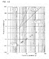
- Fig. 13 shows the relationship between the distance d between the protrusions 152 and the theoretical oil film thickness and between the distance d and the bearing rotation torque.
- Fig. 14 shows the relationship between the dimension of the rounded shape of the protrusions 152 and the theoretical oil film thickness. If the oil film between the protrusions 152 and the seal sliding surface 112 is too thin, the friction coefficient ⁇ tends to be high. If too thick, it may become difficult to effectively prevent entry of foreign objects. Taking these factors into consideration, an optimum oil film thickness should be sought within the range larger than the maximum height roughness Rz.
- Fig. 13 shows that, theoretically, if the distance d between the protrusions 152 is 2.6 mm, an approximately 3- ⁇ m-thick (i.e., way thicker than the maximum height roughness Rz of less than 1 pm) oil film is formed between the protrusions 152 and the seal sliding surface 112, and where the distance d is smaller than 2.6 mm, the oil film thickness tends to increase as the distance d decreases.
- Fig. 13 further shows that where the distance is 2.6 mm or less, the bearing rotation torque (i.e., the seal torque) tends to decrease as the distance d decreases.
- the distance d between the protrusions 152 may be therefore 2.6 mm or less. If the distance d between the protrusions 152 is less than 0.3 mm, it becomes difficult to form the seal lip 151 using a mold. Thus, the distance d is preferably 0.3 mm or over.
- Fig. 14 shows that, theoretically, if the radius of curvature of the rounded shape of the protrusions 152 is 0.15 mm, an approximately 3- ⁇ m-thick oil film is formed.
- the radius of curvature of the rounded shape of the protrusions 152 is preferably not less than 0.15 mm and less than 1.0 mm.
- the circumferential width w of the protrusions 152 is dependent upon the rounded shape of the protrusions 152, if the height h of the protrusions 152 is 0.05 mm, the radius of curvature of the rounded shape of the protrusions 152 is more preferably not less than 0.2 mm and not more than 0.7 mm.
- the height h of the protrusions 152 is 0.05 mm; the distance d between the protrusions 152 is not less than 0.3 mm and not more than 2.6 mm, the circumferential width w of the protrusions 152 is not less than 0.2 mm and not more than 0.7 mm; and the radius of curvature of the rounded shape of the protrusions 152 is not less than 0.15 mm and less than 1.0 mm.
- the seal members 150 prevent entry of foreign objects having such large particle diameters as to detrimentally affect the life of the bearing, into the bearing interior space, while at the same time, fluid lubrication minimizes the friction coefficient ⁇ due to sliding movement between the seal lip 151 and the seal sliding surface 112, thereby markedly reducing seal torque, and thus the rotation torque of the bearing (see Figs. 1 and 3 ).
- the protrusions 152 have a rounded shape, they will never be bent in the circumferential direction even if rubbed against the seal sliding surface 112 when the seal member 150 is mounted to the outer race 120, so that the protrusions reliably maintain the ability to keep the seal torque low. If, on the other hand, the protrusions have e.g., angular ridges, the individual protrusions could be bent in either of the opposite circumferential directions by being rubbed against the seal sliding surface when mounting the seal member.
- Figs. 15 and 16 show the sealed bearing 200 of the second embodiment.
- the inner race 210 of this sealed bearing 200 is formed with seal grooves 211 extending the entire circumference thereof.
- the bearing 200 has a bearing interior space defined between the inner race 210 and the outer race 220, and having the respective ends thereof sealed by seal members 230 and 240 retained in respective seal grooves 221 and 222 of the outer race 220.
- Each seal member 230, 240 includes a seal lip 231, 241 which is an axial seal lip, and an outer lip 232, 242 located outwardly of the seal lip 231, 241.
- the seal lip 231, 241 and the outer lip 232, 242 branch from a base portion attached to the metal core 233, 243.
- an axial seal lip refers to a seal lip fitted, with axial interference, to a seal sliding surface extending parallel to, or at an acute angle of less than 45 degrees relative to, the radial direction, to provide a seal between the seal lip and the seal sliding surface.
- Each seal groove 211 has a side surface as a seal sliding surface 212, 213 which gradually radially expands from the bottom of the seal groove 211 toward the raceway groove 214, and which is configured to slide relative to the seal lip 231, 241 of the corresponding seal member 230, 240.
- the seal sliding surface is inclined at an acute angle ⁇ of less than 45 degrees to the radial direction.
- the inner race 210 has a pair of shoulders 215 and 216 on the respective sides of the raceway groove 214, of which the load-bearing shoulder 215 (on the right of Fig. 15 ), on which axial loads are applied, is higher in height than the other, non-load-bearing shoulder 216 (on the left of Fig. 15 ).
- the non-load-bearing shoulder 216 is substantially as high as the shoulders of ordinary deep groove ball bearings.
- the sealed bearing 200 has a higher axial load bearing capacity than deep groove ball bearings, while its torque is as low as that of deep groove ball bearings.
- the seal sliding surfaces 212 and 213 are formed on the respective shoulders 215 and 216. Due to a large difference in outer diameter between the load-bearing shoulder 215 and the non-load-bearing shoulder 216, there is a difference in diameter between the seal sliding surface 212 on the load-bearing shoulder 215 and the seal sliding surface 213 on the non-load-bearing shoulder 216. In particular, the seal sliding surface 212, on the right of Fig. 15 , is larger in diameter than the seal sliding surface 213, on the left of Fig. 15 . This means that during operation of the bearing, the peripheral speed of the right seal sliding surface 212 is higher than that of the left seal sliding surface 213.
- each seal lip 231, 241 are formed during vulcanization to extend in the radial direction.
- the seal lips 231 and 241 are shown in the unstressed state to illustrate the interference between the protrusions 234, 244 and the seal sliding surface 212, 213.
- the seal lip 231, 241 is inclined to substantially extend along the seal sliding surface 212, 213, so that the above-mentioned oil passages and wedge-shaped gaps are formed between the protrusions 234, 244 and the seal sliding surface 212, 213 (see Fig. 3 ).
- the heights of the protrusions 234 decrease gradually toward the distal edge 235 of the seal lip 231 such that the heights are substantially zero at the distal edge 235 of the seal lip 231. Since the heights of the protrusions 234 decrease gradually toward the distal edge 235 of the seal lip 231, the undulation along the parting line for forming the protrusions 234 is less steep, so that burrs are less likely to be produced at the distal edge 235 of the seal lip 231.
- the protrusions 244, see Fig. 15 are identical in shape to the protrusions 234.
- a labyrinth gap 250 is defined between the outer lip 232 and the outer wall portion of the seal groove 211.
- the labyrinth gap 250 makes it difficult for foreign objects having particle diameters larger than 50 ⁇ m to enter the seal groove 211 from outside.
- the number of the protrusions 234 on the seal member 230, on the right of Fig. 15 differs from the number of the protrusions 244 on the seal member 240, on the left. Also, the protrusions 234 on the right seal member 230 are arranged at different circumferential angular pitches than the protrusions 244 on the left seal member 240.
- the sealing effect of the labyrinth gaps 250 compensates for such disadvantage of the (axial) seal lips 231 and 241, so that the life of the sealed bearing 200 of this embodiment is as long as that of the bearing of the first embodiment, in which radial seal lips are used.
- Fig. 17 shows a sealed bearing 300 of the third embodiment, which is the same as the second embodiment in that it is a ball bearing including an inner race 310 having a raceway groove 311, an outer race 320 having a raceway groove 321, a plurality of balls 330 disposed between the raceway grooves 311 and 321, and two seal members 340 and 350 sealing the respective ends of the bearing interior space defined between the inner race 310 and the outer race 320, and that the inner race 310 has a pair of shoulders 312 and 313 on the respective sides of the raceway groove 311, of which the load-bearing shoulder 312, on which axial loads are applied, is higher in height than the other, non-load-bearing shoulder 313.
- this sealed bearing 300 is the same as the first embodiment in that the seal members 340 and 350 include seal lips 341 and 351 in the form of radial seal lips.
- the inner race 310 has no seal grooves, and has, instead, a cylindrical seal sliding surface 314 defining the radially outer surface of the load-bearing shoulder 312, and a cylindrical seal sliding surface 315 defining the radially outer surface of the non-load-bearing shoulder 313.
- the difference in diameter between the right (in Fig. 17 ) seal sliding surface 314 and the left (in Fig. 17 ) seal sliding surface 315 is substantially equal to the corresponding difference in diameter in the second embodiment, so that the difference in peripheral speed is also substantially equal to the corresponding difference in peripheral speed in the second embodiment.
- seal member 340 and the protrusions 352 on the left (in Fig. 17 ) seal member 350 are also substantially the same as the corresponding differences in number and circumferential angular pitches in the second embodiment.
- these differences allow oil films of the same and optimum thickness to be formed between the seal member 340 and the seal sliding surface 314 and between the seal member 350 and the seal sliding surface 315, thereby reducing torque due to fluid lubricating condition, as well as the number of foreign objects that enter the bearing.
- Fig. 18 shows a sealed bearing 400 of the fourth embodiment, which is a tapered roller bearing including an inner race 410 having a raceway surface 411, a large flange 412, and a small flange 413; an outer race 420 having a raceway surface 421; a plurality of tapered rollers 430 disposed between the raceway surfaces 411 and 421 of the inner race 410 and the outer race 420; and two seal members 440 and 450 sealing the respective ends of the bearing interior space defined between the inner race 410 and the outer race 420.
- a tapered roller bearing including an inner race 410 having a raceway surface 411, a large flange 412, and a small flange 413; an outer race 420 having a raceway surface 421; a plurality of tapered rollers 430 disposed between the raceway surfaces 411 and 421 of the inner race 410 and the outer race 420; and two seal members 440 and 450 sealing the respective ends of the bearing interior space defined between the inner race
- the large flange 412 guides the large-diameter end surfaces of the tapered rollers 430, and receives axial loads.
- the small flange 413 is smaller in outer diameter than the large flange 412, and supports the small-diameter end surfaces of the tapered rollers 430, thereby preventing separation of the tapered rollers 430 from the inner race 410.
- the outer race 420 has no seal grooves, and the metal cores of the seal members 440 and 450 are press-fitted in respective ends of the inner periphery of the outer race 420.
- the seal members 440 and 450 include seal lips 441 and 442 in the form of radial seal lips.
- the inner race 410 has a cylindrical seal sliding surface 414 defining the radially outer surface of the large flange 412, and configured to slide relative to the seal lip 441 of the right (in Fig. 18 ) seal member 440 in the circumferential direction.
- the inner race 410 further includes a cylindrical seal sliding surface 415 defining the radially outer surface of the small flange 413, and configured to slide relative to the seal lip 451 of the left (in Fig. 18 ) seal member 450 in the circumferential direction.
- the protrusions 442 and 452 on the seal lips 441 and 451 define wedge-shaped gaps and oil passages as shown in Fig. 3 , which in turn make it possible to create fluid lubricating condition between the seal lip 441 and the seal sliding surface 414 and between the seal lip 451 and the seal sliding surface 415.
- the number of the protrusions 442 on the right (in Fig. 18 ) seal member 440 differs from the number of the protrusions 442 on the left (in Fig. 18 ) seal member 460. Also, the protrusions 442 on the right (in Fig. 18 ) seal member 440 are arranged at different circumferential angular pitches than the protrusions 442 on the left (in Fig. 18 ) seal member 450.
- Fig. 19 shows the relationship between the intervals d between the protrusions 442 and between the protrusions 452, and the theoretical oil film thickness.
- the gap between the seal lip 441 and the seal sliding surface 414 or between the seal lip 451 and the seal sliding surface 415 is way larger than 0.05 mm, foreign objects having particle diameters larger than 50 ⁇ m tend to enter the bearing.
- the numbers of protrusions and the circumferential angular pitches of the protrusions which are parameters that determine the intervals d between the protrusions, are determined independently of each other such that oil films having thicknesses equal to each other and optimum in preventing the above problem are formed between the right (in Fig. 18 ) seal member 440 and the seal sliding surface 414 and between the left (in Fig. 18 ) seal member 450 and the seal sliding surface 415.
- tapered roller bearings are larger in torque than ball bearings, some conventional tapered roller bearings do not include seal members.
- a large amount of lubricant tends to flow into a tapered roller bearing having no seal members due to a pumping effect inherent to its shape, so that the agitating resistance of the lubricant increases.
- foreign objects flow into the bearing together with the lubricant, it was sometimes necessary to subject both the inner and outer races of a tapered roller bearing to hardening treatment such as special heat treatment to keep the raceway surfaces free of scratches due to foreign objects.
- the sealed tapered roller bearing 400 includes the seal members 440 and 450, and thus is free of the above problems of tapered roller bearings having no seal members.
- the seal members 440 and 450 reduce the amount of lubricant flowing into the bearing due to the pumping effect, and thus reduce the agitating resistance of lubricant. This reduces the torque of the tapered roller bearing. Also, since the seal members 440 and 450 prevent foreign objects from entering the bearing together with the lubricant, no special treatment of the inner and outer races 410 and 420 is necessary. This reduces the cost of the bearing.
- Fig. 20 shows sealed (rolling) bearings according to the present invention which are used to support rotating portions of a vehicle transmission.
- the transmission shown is a multi-speed transmission, i.e., a transmission having multiple speed ratios. Its rotating portions (such as an input shaft S1 and an output shaft S2) are rotatably supported by sealed bearings B comprising the sealed bearings according to any of the above-described embodiments.
- the transmission shown includes the input shaft S1, to which the rotation of the engine of the vehicle is transmitted, the output shaft S2, which extends parallel to the input shaft S1, a plurality of gear trains G1-G4 through which the rotation of the input shaft S1 is transmitted to the output shaft S2, and clutches, not shown, mounted between the respective gear trains G1-G4 and the input shaft S1 or the output shaft S2.
- clutches mounted between the respective gear trains G1-G4 and the input shaft S1 or the output shaft S2.
- the input shaft S1 and the output shaft S2 are, as mentioned above, rotatably supported by the sealed bearings B.
- the sealed bearings B are arranged in the transmission such that their sides are splashed with lubricating oil splashed due to rotation of the gears or injected from nozzles (not shown) in the housing H.
- the protrusions have rounded shapes, but their shapes are not limited to rounded shapes provided fluid lubricating condition can be created between the protrusions and the seal sliding surface while the relative peripheral speed therebetween is higher than a predetermined value.
- the protrusions may have chamfers such as rounded chamfers or flat chamfers.
- a plurality of protrusions are arranged at equal intervals in the circumferential direction, but instead, a plurality of protrusions may be arranged at unequal intervals in the circumferential direction, or a single protrusion may be used located at one circumferential position. Oil passages are defined by such a single protrusion, so that such a single protrusion serves to reduce the seal torque.
- the seal member comprises a metal core and a vulcanized rubber section, but the seal member may comprise a single material, provided its seal lip can be fitted with interference fit.
- the seal member may entirely comprise a rubber or a resin.
- the bearing is a radial bearing of which the inner race is rotatable, but may be a thrust bearing of which the outer race is rotatable.
Abstract
Description
- The present invention relates to a sealed bearing comprising a rolling bearing and seal members.
- Foreign objects such as wear dust produced from gears exist in transmissions mounted on vehicles such as automobiles and construction machinery. Rolling bearings used in such transmissions therefore include seal members which prevent entry of foreign objects into the bearing interior space, thereby preventing premature breakage of the rolling bearings.
- Such seal members usually include a seal lip made from e.g., rubber. Bearing parts that rotate in the circumferential direction relative to the seal members, such as bearing races or slingers, are formed with seal sliding surfaces with which the seal lips of the seal members are in sliding contact. In this arrangement, since the seal lips are in sliding contact with the respective seal sliding surfaces over the entire circumference thereof, the drag resistance of the seal lips (seal torque) is high, which results in increased bearing torque. Also, the friction due to such slide contact increases the temperature of the rolling bearing. The higher the temperature of the bearing, the more strongly the seal lips tend be pressed against the seal sliding surfaces due to an increased pressure difference between the interior space of the bearing and the exterior of the bearing, thus further increasing the friction therebetween.
- In order to reduce the seal torque of such a seal member, which is in contact with the seal sliding surface, the below-identified
Patent Document 1 proposes to subject the seal sliding surface to shot peening to form minute undulations thereon such that the seal sliding surface has a maximum roughness Ry of 2.5 micrometers or less, thereby promoting the formation of oil film between the seal lip and the seal sliding surfaces by lubricating oil trapped in the recesses of the minute undulations. - Patent Document 1:
JP Patent Publication 2007-107588A - By subjecting the seal sliding surface to shot peening as disclosed in
Patent Document 1, the seal torque decreases because the area of the portion of the seal sliding surface that is brought into sliding contact with the seal lip decreases. However, since it is difficult to significantly reduce this area, the seal torque cannot be significantly reduced, either. - Immediately after the bearing begins to operate, oil film forms easily since the temperature of lubricating oil is relatively low, and its viscosity is relatively high. However, as the bearing is operated continuously, the oil temperature rises and its viscosity decreases, thus making the formation of oil film increasingly difficult. Also, the higher the operating speed of the bearing, the higher the peripheral speed of the seal sliding surface relative to the seal lip, so that a larger amount of heat is generated due to friction between the seal lip and the seal sliding surface, resulting in an increased oil temperature and the progression of wear of the seal lip. Thus, the maximum speed, i.e., maximum rotational speed, of the sealed bearing disclosed in
Patent Document 1 is limited due to its lubricating conditions. That is, while there is a strong demand for sealed bearings which are capable of supporting rotating parts in the drive train of an electric vehicle (EV) and capable of being operated at high speed, sealed bearings whose seal sliding surfaces are subjected to shot peening for reduced torque cannot meet this demand. - While a bearing with non-contact seal members is free of seal torque, it is difficult to accurately manage the sizes of the gaps between the non-contact seal members and bearing parts to prevent entry of foreign objects larger in diameter than a predetermined threshold.
- The seal lip of such a seal member is molded in upper and lower molds with the parting line, i.e., the line along which the upper and lower molds abut each other, located at the distal edge of the seal lip. As a result, material forming the seal lip could partially stick out of the distal edge into the parting line, forming burrs. Such burrs, which are initially integral with the distal edge of the seal member, may separate from the seal lip during operation of the bearing, and could clog oil filters and oil passages.
- An object of the present invention is to reduce torque and increase speed of a sealed bearing, while preventing entry of foreign objects larger in diameter than a predetermined threshold, and also preventing formation of burrs at the distal edge of the seal lip..
- In order to achieve this object, the present invention provides a sealed bearing defining a bearing interior space, the sealed bearing comprising: a seal member separating the bearing interior space from an exterior of the bearing, the seal member including a seal lip; a seal sliding surface configured to slide relative to the seal lip in a circumferential direction; and a protrusion formed on one circumferential portion of the seal lip, and defining oil passages extending between the seal sliding surface and the seal lip, the oil passages communicating with the bearing interior space and the exterior of the bearing; wherein the protrusion is shaped and arranged such that fluid lubricating condition can be created between the seal lip and the seal sliding surface, the seal lip has a distal edge that defines a radially inner diameter of the seal lip when the seal member is in a natural state and not stressed by any external force, and the protrusion has a height that gradually decreases toward the distal edge of the seal lip.
- With this arrangement, the protrusion defines oil passages between the seal sliding surface and the seal lip, and as the bearing rotates, lubricating oil in the oil passages is pulled into the space between the seal sliding surface and the seal lip due to the wedge effect, so that oil film can be easily formed therebetween. As a result, the bearing can be operated with the seal lip and the seal sliding surface completely separated from, and out of contact with, each other (i.e., with fluid lubricating condition created therebetween), so that the seal torque can be reduced to practically zero. This practically prevents the wear of the seal lip, and reduces heat buildup due to sliding movement between the seal lip and the seal sliding surface. This increases the maximum allowable peripheral speed of the seal sliding surface relative to the seal lip, which in turn makes it possible to operate the sealed bearing assembly at a high speed that was not attainable with conventional sealed bearings. It is also possible to prevent sticking of the seal lip.
- It is possible to determine the maximum diameter of foreign objects that can pass through the oil passages based on the protruding height of the protrusion. Thus, it is possible to freely determine the minimum particle diameter of foreign objects that cannot pass through the oil passages into the bearing.
- The shape of the seal lip when the seal member is in an unstressed natural state corresponds to the shape of the seal lip when the seal lip is formed in molds. In this state, the distal edge of the seal lip that defines the radially inner diameter of the seal lip is located on the parting line along which the upper and lower molds abut each other. If the protrusion extends to the distal edge of the seal lip, the higher the protrusion, the steeper the undulation for forming the protrusion tends to be at the parting line. As a result, the pressure tends to be high at the undulation during molding of the seal lip, so that burrs tend to form. Thus, if the protrusion is formed such that its height decreases gradually toward the distal edge of the seal ring, the undulation for forming the protrusion is less steep at the parting line, or no undulation forms at the parting line. This prevents the formation of burrs at the distal edge of the seal lip.
- Therefore, according to the present invention, it is possible to reduce the torque and increase the speed, of a sealed bearing, while preventing entry of foreign objects having particle diameters larger than a predetermined value, and also preventing the formation of burrs at the distal edge of the seal lip.
-
-
Fig. 1 is a sectional view of a sealed bearing assembly according to a first embodiment of the present invention. -
Fig. 2 is an enlarged view of (and around) a seal lip of a seal member on the right ofFig. 1 . -
Fig. 3 is an enlarged sectional view taken along line III-III ofFig. 2 . -
Fig. 4 is a partial front view of a seal lip of the first embodiment, as seen in the axial direction. -
Fig. 5 is a partial perspective view of a seal lip of the first embodiment. -
Fig. 6A shows how the seal lip ofFig. 5 is formed by vulcanization. -
Fig. 6B schematically illustrates the seal lip formed in the process ofFig. 6A . -
Fig. 7A shows how a hypothetical seal lip is formed by vulcanization. -
Fig. 7B schematically illustrates the seal lip formed in the process ofFig. 7A . -
Fig. 8 shows the numbers of foreign objects in lubricating oil in vehicle transmissions (AT/MT) for respective particle diameter ranges. -
Fig. 9 is a circular graph showing the percentages of foreign objects in the respective particle diameter ranges shown inFig. 8 . -
Fig. 10 shows the numbers of foreign objects in lubricating oil in vehicle transmissions (CVT) for respective particle diameter ranges. -
Fig. 11 is a circular graph showing the percentages of foreign objects in the respective particle diameter ranges shown inFig. 10 . -
Fig. 12 is a lubrication region chart showing a fluid lubricating mode in the first embodiment. -
Fig. 13 is a graph showing, in the first embodiment, the relationship between the intervals between protrusions and the theoretical oil film thickness and between the intervals between the protrusions and the bearing rotation torque. -
Fig. 14 is a graph showing, in the first embodiment, the relationship between the dimension of a rounded shape of protrusions and the theoretical oil film thickness. -
Fig. 15 is a sectional view of a sealed bearing according to a second embodiment of the present invention. -
Fig. 16 is an enlarged view of (and around) a seal lip of a seal member on the right ofFig. 15 . -
Fig. 17 is a sectional view of a sealed bearing according to a third embodiment of the present invention. -
Fig. 18 is a sectional view of a sealed bearing according to a fourth embodiment of the present invention. -
Fig. 19 illustrates, in the fourth embodiment, the relationship between the intervals between protrusions and the theoretical oil film thickness. -
Fig. 20 is a sectional view of a transmission including sealed bearings according to the present invention. - Preferred arrangements of this invention are described.
- In a first preferred arrangement, there is a flat surface between the distal edge of the seal lip and the protrusion. In the first preferred arrangement, since there is no undulation for forming the protrusion at the parting line, it is possible to prevent the formation of burrs at the distal edge of the seal lip.
- In a second arrangement, the protrusion comprises a plurality of protrusions that are arranged at equal intervals over the entire circumference. According to the second arrangement, it is possible to reliably form uniform oil film over the entire circumference of the seal sliding surface.
- In a third arrangement, wedge-shaped gaps are defined between the protrusion or each of the protrusions and the seal sliding surface such that each wedge-shaped gap is larger on the corresponding oil passage than on the side of the protrusion. With the third arrangement, as the bearing rotates, lubricating oil in the oil passages can be reliably pulled toward the protrusion(s) due to the wedge-effect, so that oil film reliably forms between the protrusion(s) and the seal sliding surface. Since the protrusion(s) is shaped to define a wedge-shaped gap, its sliding contact area is small, which reduces the sealing torque.
- In a fourth arrangement, protrusion(s) extends in a direction perpendicular to the circumferential direction, and has a rounded shape such that the distance between the protrusion and the seal sliding surface gradually decreases from the respective ends of the protrusion toward the center of the protrusion, with respect to the circumferential width of the protrusion. Such rounded shape reduces the sliding contact area of the protrusion, i.e., allows the protrusion to be in sliding contact with the seal sliding surface along a linear area. By using the rounded shape, the wedge angle of each wedge-shaped gap decreases gradually in one direction. This effectively increases the wedge effect, thus increasing the oil pressure at the linear contact area, which in turn makes it possible to easily create fluid lubricating condition between the protrusion and the seal sliding surface. Even if the protrusion is rubbed against the seal sliding surface when mounting the seal member, since the protrusion has a rounded shape, it will never be bent in the circumferential direction, so that there is no possibility that the seal torque reducing capability will be damaged when mounting the seal member.
- A first embodiment of the present invention is described with reference to
Figs. 1-14 . As shown inFig. 1 , the first embodiment is a sealedbearing 100 including aninner race 110, anouter race 120, a plurality of rollingelements 140 retained by aretainer 130, and twoseal members 150. Throughout the specification, the direction of the center axis of the sealedbearing 100 is referred to as the "axial direction", a direction perpendicular to the center axis of the sealedbearing 100 is referred to as a "radial direction", and a circumferential direction around the center axis of the sealedbearing 100 is simply referred to as the "circumferential direction". - The
inner race 110 and theouter race 120 define an annular, bearinginterior space 160 in which the rollingelements 140 are disposed such that the rollingelements 140 roll around the center axis of the sealedbearing 100 while being held between theinner race 110 and theouter race 120. Lubricating oil is supplied to the bearinginterior space 160 in the form of grease or from an oil bath. - The
inner race 110 is mounted to a rotary shaft (not shown) so as to rotate together with the rotary shaft. The rotary shaft may be a rotary member of a vehicle transmission or differential. Theouter race 120 is mounted to a member, such as a housing or a gear, that supports loads from the rotary shaft. - The sealed
bearing 100 is a deep groove ball bearing, of which the rollingelements 140 are balls. Theinner race 110 and theouter race 120 haveraceways Fig. 1 ) one-third of the circumference of the rollingelement 140, and continuously extending the entire circumference of therespective race - The
seal members 150 are retained inseal grooves 122 formed in the respective ends of the inner periphery of theouter race 120. In particular, theseal members 150 are mounted to theouter race 120 by having the outer peripheral edges thereof press-fitted in therespective seal grooves 122. - The
seal members 150 separate the bearinginterior space 160 from the exterior of thebearing 100. In the exterior of thebearing 100, i.e., the space outside theseal members 150, there exist foreign objects which vary according to the device or structure in which the sealedbearing 100 is mounted, such as wear dust from gears or clutches, or minutely crushed stone. Such powdery foreign objects could reach the area around theseal members 150 due to the flow of lubricating oil or the ambient air. Theseal members 150 prevent entry of foreign objects into the bearinginterior space 160 from outside thebearing 100. - Each
seal member 150 includes aseal lip 151 protruding from its inner peripheral portion like a tongue. Theinner race 110 has, on its outer periphery,seal sliding surfaces 112 that slide in the circumferential direction relative to therespective seal lips 151. Theseal sliding surfaces 112 are cylindrical surfaces, that is, they extend the entire circumference of theinner race 110. Theseal lips 151 are radial lips. As used herein, a radial lip refers to a seal lip that is in contact with a seal sliding surface extending in the axial direction or inclined at an acute angle of 45 degrees or less relative to the axial direction, with radial interference relative to the seal sliding surface, thereby providing a seal between the seal lip and the seal sliding surface. - The
seal lips 151 are in contact with the respectiveseal sliding surfaces 112 with radial interference therebetween. The radial interference causes theseal lips 151 to be radially pressed against theseal sliding surfaces 112, and thus elastically deformed so as to be bent outwardly. In other words, theseal lips 151 are strained due to the radial interference. Mounting errors, manufacturing errors, and any other errors of theseal members 150 are absorbed by theseal lips 151 being elastically bent. -
Fig. 2 shows an enlarged view of (and around) theseal lip 151 of one of theseal members 150 ofFig. 7 .Fig. 3 shows a sectional view taken along line III-III ofFig. 2 . Theseal member 150 is designed such that the gaps between theseal lip 151 and the seal sliding surface 112 (including the gaps defined by oil passages 170) in the direction perpendicular to theseal sliding surface 112 are the narrowest at the section ofFig. 3 .Fig. 4 shows the contour of theseal lip 151 as seen in the axial direction from the bearing interior space while theseal member 150 is not yet mounted on the bearing and thus not deformed by an external force. (This state is hereinafter referred to as the "unstressed state".) - As seen in
Figs. 2-4 , theseal lip 151 hasprotrusions 152 protruding in the directions perpendicular to theseal sliding surface 112, i.e., in the normal directions perpendicular to the tangential directions of theseal sliding surface 112. Since theseal sliding surface 112 is a cylindrical surface having a center on the center axis of the bearing, the above-mentioned normal directions are the radial directions. -
Fig. 5 is an enlarged perspective view of a portion of theseal lip 151 including some of theprotrusions 152 when theseal lip 151 is in an unstressed state. As shown inFigs. 4 and5 , theseal lip 151 has adistal edge 153 that defines the radially inner diameter of theseal lip 151 when theseal member 150 is in the unstressed state. - As shown in
Figs. 2-5 , theprotrusions 152 extend in the direction perpendicular to the circumferential direction to the area close to thedistal edge 153 of theseal lip 151 such that theprotrusions 152 exist on substantially the entire width of the portion of theseal lip 151 that is in contact with theseal sliding surface 112 with radial interference. - The
protrusions 152 are arranged at regular circumferential intervals d. In other words, when theseal lip 151 is seen in the axial direction, theprotrusions 152 are arranged radially at regular angular pitches θ corresponding to the circumferential intervals d, i.e., lie on radial lines extending from the center axis of theseal member 150. (This center axis is not shown, and coincides with the center axis of the bearing). - Since the
radially extending protrusions 152 are disposed adjacent to thedistal edge 153 of theseal lip 151, by suitably determining the circumferential intervals d, and the circumferential widths w of therespective protrusions 152, it is possible to bring theseal lip 151 into sliding contact with theseal sliding surface 112 only at theprotrusions 152, and thus to always define theoil passages 170 between theprotrusions 152. That is, intervals d and widths w are determined such that, when mounting theseal member 150, theprotrusions 152, which are in contact with theseal sliding surfaces 112, remain uncollapsed by the stretching force of theseal ring 151 so that theoil passages 170 form between the respective circumferentially adjacent pairs ofprotrusions 152, and lubricant can flow into the bearinginterior space 160 from outside the bearing through theoil passages 170. Lubricating oil that has flowed into the bearinginterior space 160, or the base oil of grease sealed in the bearinginterior space 160 can flow through theoil passages 170 to the outside of the bearing. - The maximum particle diameter of foreign objects that can pass through the
oil passages 170 can be determined based on the heights h of theprotrusions 152, i.e., their dimensions in the direction perpendicular to theseal sliding surface 112. Thus, in the first embodiment, it is possible to freely determine the minimum particle diameter of foreign objects that cannot pass through theoil passages 170 into the bearinginterior space 160. - Wear dust greater than 50 micrometers in particle diameter could cause premature damage to the rolling bearing. If the heights h of the
protrusions 152 are 0.05 mm or less, such wear dust is unable pass through theoil passages 170. On the other hand, for smooth flow of oil through theoil passages 170, the heights h of theprotrusions 152 are preferably 0.05 mm or over. - Wedge-shaped gaps are defined between each
protrusion 152 and theseal sliding surface 112 such that the width of each wedge-shaped gap gradually increases in the circumferential direction toward the correspondingoil passage 170. Referring toFig. 3 , when theinner race 110 rotates, and thus, theseal sliding surface 112 rotates in the circumferential direction (for example, in the direction of the arrow A inFig. 3 ) relative to theseal lip 151, lubricating oil (shown in dotted pattern) in eachoil passage 170 is pulled into the space between theseal sliding surface 10 and the corresponding one of theprotrusions 152 of theseal lip 151, due to the rotation of theseal sliding surface 112, so that oil film is formed easily therebetween, thereby reducing the friction coefficient (µ) between theseal lip 151 and theseal sliding surface 112, which in turn reduces the seal torque. Theoil passages 170 allow oil to flow more easily between the bearinginterior space 160 and the exterior of the bearing. This prevents an excessive rise in temperature of the sealedbearing 100, which in turn prevents sticking of theseal lip 151. - As shown in
Fig. 5 , theprotrusions 152 gradually decrease in height toward thedistal edge 153 of theseal lip 151. In order to gradually reduce the height of eachprotrusion 152 toward thedistal edge 153 of theseal lip 151, the radius of curvature of the rounded surface of theprotrusion 152 is gradually increased, while the center of curvature of the rounded surface is gradually moved outwardly, toward thedistal edge 153 of theseal lip 151. - The heights h of the
protrusions 152 are practically zero at thedistal edge 153 of theseal lip 151. In other words, theprotrusions 152 terminate short of thedistal edge 153 of theseal lip 151, so that there is aflat surface 155 extending the entire circumference of theseal lip 151 between theprotrusions 152 and thedistal edge 153 of theseal lip 151. Thus, thedistal edge 153 of theseal lip 151 forms a boundary between theflat surface 155, which extends the entire circumference of theseal lip 151 and faces the bearing interior space, and the outer surface of theseal lip 151 which extends the entire circumference of theseal lip 151. - As shown in
Fig. 1 , eachseal member 150 comprises ametal core 156 in the form of a metal plate, and a vulcanizedrubber section 157 adhered to at least a radially inner portion of themetal core 156. Theseal lip 151 is a tongue-shaped portion of the vulcanizedrubber section 157. Themetal core 156 is an annular member, i.e., a member that extends the entire circumference, formed by pressing. The vulcanizedrubber section 157 is formed by vulcanizing a rubber material. Theseal member 150 is formed, for example, by placing themeal core 156 in a mold, and forming the vulcanizedrubber section 157 by vulcanization such that themetal core 156 and the vulcanizedrubber section 157 form an integral body. The vulcanizedrubber section 157 may be adhered to theentire metal core 156, or adhered only to the radially inner portion of themetal core 156. -
Figs. 6A and 6B show how theseal lip 151 is formed by vulcanization. For better understanding,Figs. 6A and 6B only schematically show the shape of theseal lip 151, and other elements. Theseal lip 151 is formed by attaching, by vulcanization, a rubber sheet to themetal core 156. During vulcanization, the rubber portion of theseal member 150, including theseal lip 152, is formed by sandwiching the rubber sheet between an upper mold Mp1 and a lower mold Mp2. The upper mold Mp1 is arranged over the lower mold Mp2 with respect to the vertical direction such that the vertical direction corresponds to the axial direction of the bearing. Therefore, thedistal edge 153 of theseal lip 151, which defines the radially inner diameter of theseal lip 151 when the seal member is in its unstressed state, forms a boundary between the upper surface of theseal lip 151, which is in contact with the transfer surface of the upper mold Mp1, and the lower surface of theseal lip 151, which is in contact with the transfer surface of the lower mold Mp2. In other words, thedistal edge 153 of theseal lip 151 is located on the parting line Pl of the upper mold Mp1 and the lower mold Mp2, where the upper mold Mp1 and the lower mold Mp2 meet. -
Figs. 7A and 7B show a hypothetical seal lip 151' of which the protrusions 152' extend up to the distal edge 153' of the seal lip 151'. In this case, since undulations for forming such protrusions 152' extend up to the parting line Pl, burrs 158 as shown inFig. 7B tend to be formed after vulcanization. Ifsuch burrs 158 separate from the seal lip 151' during operation of the bearing, they could clog oil filters and lubricating oil circulating paths. - On the other hand, by providing, as shown in
Figs. 6A and 6B , theflat surface 155 between theprotrusions 152 and thedistal edge 153 of theseal lip 151, undulations for forming theprotrusions 152 do not extend to the parting line Pl, so that noburrs 158 as shown inFigs. 7A and 7B are formed. The arrangement of the first embodiment thus prevents the formation of burrs at thedistal edge 153 of theseal lip 151 of theseal member 150 when forming theseal lip 151 by vulcanization. - In the first embodiment, the heights of the
protrusions 152 are zero at thedistal edge 153 of theseal lip 151, and there is theflat surface 155 between theprotrusions 152 and thedistal edge 153 of theseal lip 151. Alternatively, the protrusions may extend up to the distal edge of the seal lip, as far as their heights gradually decrease toward the distal edge of the seal lip. In this arrangement, since undulations for forming the protrusions are less steep at the parting line, burrs are less likely to be formed at the distal edge of the seal lip. - In the first embodiment, it is possible to form the
protrusions 152 on theseal lip 151 during vulcanization. Theseal sliding surface 112 may be a cylindrical surface or a groove having the same section over the entire circumference thereof, and can be formed directly on one of the raceways, so that theseal sliding surface 112 can be formed easily. - The
seal lip 151 and theseal sliding surface 112 are shaped and arranged such that the (solid)protrusions 152 are not substantially deformed (i.e., not deformed such that the lubricating properties between theprotrusions 152 and theseal sliding surface 112 are affected) due to the stretching force of theseal lip 151 and the oil pressure of lubricating oil. Thus, during operation of the bearing, theprotrusions 152 maintain the shape when theseal lip 151 is formed by vulcanization by transferring the shape of the mold. - The sealed
bearing 100 is intended to be used in a vehicle transmission. Ordinarily, oil is supplied to a sealed bearing in a vehicle transmission by splashing, from an oil bath, or by nozzle injection. Therefore, lubricating oil exists around the seal lips of the seal members fixed to the inner race or the outer race of such a sealed bearing. Lubricating oil used for such a sealed bearing race is also used to lubricate parts of the transmission to be lubricated, such as gears. Such lubricating oil is circulated by an oil pump, and filtered by an oil filter in the circulation path of the lubricating oil. - The inventors of the present application recovered lubricating oil from eight automatic transmission (AT) or manual transmission (MT) vehicles which had been actually used on the road, and whose odometer readings were different from each other. Then, for the lubricating oil recovered from each of the eight vehicles, the numbers of (particulate) foreign objects in the lubricating oil for respective ranges of the particle diameters of the foreign objects were counted, and are shown in the graph of
Fig. 8 . The materials of the foreign objects were also investigated. In the graph ofFig. 8 , the vertical axis indicates, on logarithmic scale, the number of foreign objects per 100 ml of lubricating oil in each of particle diameter ranges of not less than 5 µm and less than 15 pm, not less than 15 µm and less than 25 µm, not less than 20 µm and less than 50 pm, not less than 50 µm and less than 100 pm, and not less than 100 µm. The horizontal axis indicates the travel distances of the respective vehicles. Foreign objects having diameters smaller than 5 µm were not counted. The numbers of foreign objects in the respective particle diameter ranges were counted by a particulate foreign object weighing method, using a measuring machine made by Hyac-Royco, Model No. 8000A. The circular graph ofFig. 9 shows the percentages (in number) of the foreign objects in the respective particle diameter ranges shown inFig. 8 . -
Fig. 10 is a graph similar toFig. 8 and showing the numbers of foreign objects in the respective particle diameter ranges for lubricating oil recovered from ten continuously variable transmission (CVT) vehicles. The circular graph ofFig. 11 shows these numbers in percentage. While the manufactures, the makes, and the travel distances of the abovementioned eight and ten vehicles vary, comparison ofFigs. 8 and 9 withFigs. 10 and 11 reveals that foreign objects in the lubricating oil from the AT/MT vehicles, in which a larger number of gears are used, are larger in particle diameter and number than those in the lubricating oil from the CVT vehicles. Irrespective of the type of the transmission, the number of foreign objects in the particle diameter range of not more than 50 µm accounted for 99.9% or over of the total number of foreign objects in the lubricating oil. The number of foreign objects larger in particle diameter than 50 µm was less than 1000 for an AT/MT vehicle, and less than 200 for a CVT vehicle, irrespective of the travel distance. This indicates that due to improved performance of today's oil filters, foreign objects remaining in lubricating oil in today's vehicles are smaller in size (as a result of larger foreign objects being removed by oil filters). - Next, investigation was made, if lubricating oil in the bearing interior contains foreign objects, of the relationship between the numbers of such foreign objects in the respective particle diameter ranges, and the life of the bearing. The investigation revealed that, while the larger the number of foreign objects having larger particle diameters, the shorter the bearing life tends to be, if the number of foreign objects having
particle diameters 50 µm or over is sufficiently small as in the environment in today's transmissions, even if a bearing in such a transmission has no seals, and thus the lubricating oil in the transmission can freely flow into the bearing, the life ratio of the bearing (ratio of the actual life of the bearing to the calculated life) is sufficient for actual use in an automotive transmission (for example, this ratio is about 7 to 10). - Based on this discovery, it can be said that if a sealed bearing used to support a rotary portion of a vehicle drive member such as a transmission or a differential includes seal members capable of preventing foreign objects having particle diameters of more than 50 µm from entering the bearing interior, and if lubricating oil is supplied after being filtered by an oil filter, the bearing life will never be influenced by foreign objects even though foreign objects having particle diameters of 50 µm or less can enter the bearing interior. By configuring the seal members such that foreign objects having particle diameters of 50 µm or less can enter the bearing interior, sufficient amount of lubricating oil can pass through the space between each seal lip and the seal sliding surface, so that in cooperation with the above-described wedge effect, it is possible to create fluid lubricating condition between the seal lip and the seal sliding surface.
- For these reasons, as shown in
Figs. 2 and3 , theseal lip 151 is designed such that the portions of theprotrusions 152 that can be brought into sliding contact with theseal sliding surface 112 have a maximum height h of 0.05 mm. The interference between eachprotrusion 152 and theseal sliding surface 112 is the highest at the portion of theprotrusion 152 having the maximum height h. Since deformation of theprotrusions 152 during operation of the bearing is ignorable, the gaps between theseal lip 151 and the seal sliding surface 112 (including the gaps defined by the oil passages 170) in the direction perpendicular to theseal sliding surface 112 are equal to the maximum height h of theprotrusions 152, and do not substantially exceed 0.05 mm, at their narrowest portions. Thus, it is possible to substantially prevent foreign objects having particle diameters of more than 50 µm in lubricating oil from passing through theoil passages 170. - Each
protrusion 152 has a rounded shape such that the distance between theprotrusion 152 and theseal sliding surface 112 decreases from its ends toward its center with respect to the circumferential width w thereof, over the entire radial length of theprotrusion 152. The rounded shape of eachprotrusion 152 allows theprotrusion 152 to come into sliding contact with theseal sliding surface 112 along a linear area on an imaginary axial plane Pax which passes through the center of theprotrusion 152 with respect to its circumferential width, and on which the rounded shape of theprotrusion 152 has its center of curvature. - When the
seal sliding surface 112 rotates in the direction of arrow A inFig. 3 relative to theseal lip 151, lubricating oil in theoil passages 170 is pulled into wedge-shaped gaps between theprotrusions 152 and theseal sliding surface 112. Since each wedge-shaped gap has a wedge angle that gradually decreases from its wide end facing theoil passage 170, in which there is lubricating oil to be pulled into the wedge-shaped gap, toward its narrow end, the closer to the linear area (on the imaginary axial plane Pax) along which theprotrusion 152 can come into sliding contact with theseal sliding surface 112, the stronger the wedge effect tends to be. This effectively increases the oil pressure of the oil film at the linear area to such an extent that theprotrusion 152 is completely separated from theseal sliding surface 112, and the oil film becomes thick at the linear area. This in turn makes it easier to create fluid lubricating condition between theprotrusion 152 and theseal sliding surface 112. - If the
protrusion 152 is completely separated from theseal sliding surface 112 by oil film, there exists fluid lubricating condition, in which theseal sliding surface 112 slides relative to theprotrusion 152 while not in direct contact with theprotrusion 152. By forming such oil film between eachprotrusion 152 and theseal sliding surface 112, fluid lubricating condition is created between theseal lip 151 and theseal sliding surface 112. - In order to easily create such fluid lubricating condition, the stretching force of the
seal lip 151, which corresponds to the interference between theseal lip 151 and theseal sliding surface 112, is preferably as small as possible. For this purpose, the base portion of theseal lip 151 at which theseal lip 151 is bent (i.e., deformed) outwardly has preferably as small a wall thickness as possible. - The smaller the maximum height roughness Rz, the smaller the thickness of oil film necessary to create fluid lubricating condition can be. Thus, the
seal sliding surface 112 is not subjected to shot peening so that the maximum height roughness Rz is less than 1 µm. The maximum height roughness Rz herein used refers to what is defined under JIS B0601: 2013. - The smaller the distances d between the circumferentially adjacent pairs of
protrusions 152, i.e., the larger the number of theprotrusions 152, the larger number ofprotrusions 152 any point of theseal sliding surface 112 passes when theseal sliding surface 112 rotates once relative to theseal lip 151. This makes it easier to form a continuous oil film over the entire circumference of theseal sliding surface 112, and to eliminate any portion where oil is not subjected to the wedge effect between eachprotrusion 152 and theseal sliding surface 112, so that fluid lubricating condition can be created more easily. - The larger the rounded shape of each protrusion 152 (i.e., the radius of curvature of the
surface 154 of the protrusion 152), the more easily the wedge effect is created. - The inventors of the present application calculated the theoretical oil film thickness between the
protrusions 152 and theseal sliding surface 112 when the heights h of theprotrusions 152 are 0.05mm, the intervals d between theprotrusions 152 are not less than 0.3 mm and not more than 2.6 mm, the circumferential widths w of theprotrusions 152 are not less than 0.2 mm and not more than 0.7 mm, and the rounded shape of theprotrusions 152 is not less than 0.15 mm and less than 1.0 mm, with the peripheral speed of the seal sliding surface 112 (i.e., the speed at which theseal sliding surface 112 rotates in the circumferential direction relative to the seal lip 151) within the range of 0.02-20.2 m/s. In this calculation, "CVTF" was simulated, in which a pulley and a belt of a CVT were lubricated, when the oil temperature was 30°C and 120°C. The calculation results revealed that under these use conditions, in a lubrication region chart for line contact based on viscosity parameter gv and elasticity parameter ge, which are non-dimensional numbers determined by Greenwood and Johnson, lubricating oil is distributed in either one of the equiviscous-rigid body region (R-I lubricating mode) and the equiviscous-elastic body region (E-I mode, soft EHL), which means fluid lubricating condition.Fig. 12 shows the distribution of the calculation results in the above-described lubrication region chart. - The inventors of the present application discovered, by calculation, the relationship between the distance d between the
protrusions 152, shown inFigs. 3 and4 , and the theoretical oil film thickness between theprotrusions 152 and theseal sliding surface 112. The inventors of the present application further discovered, by calculation, the relationship between the rounded shape of theprotrusions 152 and the theoretical oil film thickness between theprotrusions 152 and theseal sliding surface 112. The theoretical oil film thickness was calculated using the minimum film thickness calculating equation of Martin for the R-I mode, or using the minimum film thickness calculating equation of Herrebrugh for the E-I mode. The inventors of the present application further discovered, by experiment, the relationship between the distance d between theprotrusions 152 and the rotation torque of the sealedbearing 100.Fig. 13 shows the relationship between the distance d between theprotrusions 152 and the theoretical oil film thickness and between the distance d and the bearing rotation torque.Fig. 14 shows the relationship between the dimension of the rounded shape of theprotrusions 152 and the theoretical oil film thickness. If the oil film between theprotrusions 152 and theseal sliding surface 112 is too thin, the friction coefficient µ tends to be high. If too thick, it may become difficult to effectively prevent entry of foreign objects. Taking these factors into consideration, an optimum oil film thickness should be sought within the range larger than the maximum height roughness Rz. -
Fig. 13 shows that, theoretically, if the distance d between theprotrusions 152 is 2.6 mm, an approximately 3-µm-thick (i.e., way thicker than the maximum height roughness Rz of less than 1 pm) oil film is formed between theprotrusions 152 and theseal sliding surface 112, and where the distance d is smaller than 2.6 mm, the oil film thickness tends to increase as the distance d decreases.Fig. 13 further shows that where the distance is 2.6 mm or less, the bearing rotation torque (i.e., the seal torque) tends to decrease as the distance d decreases. The distance d between theprotrusions 152 may be therefore 2.6 mm or less. If the distance d between theprotrusions 152 is less than 0.3 mm, it becomes difficult to form theseal lip 151 using a mold. Thus, the distance d is preferably 0.3 mm or over. -
Fig. 14 shows that, theoretically, if the radius of curvature of the rounded shape of theprotrusions 152 is 0.15 mm, an approximately 3-µm-thick oil film is formed. Thus, if the height h of theprotrusions 152 is 0.05 mm, and considering the fact that the seal lip is formed in a mold, the radius of curvature of the rounded shape of theprotrusions 152 is preferably not less than 0.15 mm and less than 1.0 mm. Also, since the circumferential width w of theprotrusions 152 is dependent upon the rounded shape of theprotrusions 152, if the height h of theprotrusions 152 is 0.05 mm, the radius of curvature of the rounded shape of theprotrusions 152 is more preferably not less than 0.2 mm and not more than 0.7 mm. - In view of the above calculation results, in the first embodiment, the height h of the
protrusions 152, shown inFigs. 2-4 , is 0.05 mm; the distance d between theprotrusions 152 is not less than 0.3 mm and not more than 2.6 mm, the circumferential width w of theprotrusions 152 is not less than 0.2 mm and not more than 0.7 mm; and the radius of curvature of the rounded shape of theprotrusions 152 is not less than 0.15 mm and less than 1.0 mm. By providing theseal lip 151 withsuch protrusions 152, it is possible to create fluid lubricating condition between theseal lip 151 and theseal sliding surface 112 while theseal sliding surface 112 is rotating at a peripheral speed of 0.2 m/s or over. In this arrangement, while the peripheral speed of theseal sliding surface 112 is less than 0.2 m/s, boundary lubricating condition prevails between theprotrusions 152 and theseal sliding surface 112. However, since a bearing in a vehicle transmission quickly reaches the peripheral speed of 0.2 m/s once it begins to rotate, fluid lubricating condition is created between theseal lip 151 and theseal sliding surface 112 substantially over the entire period of operation of the bearing. - With the sealed
bearing 100 of the first embodiment, theseal members 150 prevent entry of foreign objects having such large particle diameters as to detrimentally affect the life of the bearing, into the bearing interior space, while at the same time, fluid lubrication minimizes the friction coefficient µ due to sliding movement between theseal lip 151 and theseal sliding surface 112, thereby markedly reducing seal torque, and thus the rotation torque of the bearing (seeFigs. 1 and3 ). - With the sealed
bearing 100 of the first embodiment, even while the bearing is being rotated at peripheral speeds at which conventional sealed bearings would suffer from such problems as wear of the seal lips, and heat buildup due to sliding movement between the seal lip and the seal sliding surface (e.g., at 30 m/s and over), since fluid lubricating condition keeps theseal lip 151 and theseal sliding surface 112 out of direct contact with each other, it is possible to keep theseal lip 151 practically free of wear, and to reduce heat buildup due to sliding movement between the seal lip and the seal sliding surface. This in turn makes it possible to operate the sealedbearing 100 of the first embodiment at speeds that were not attainable with conventional sealed bearings. - With the sealed
bearing 100 of the first embodiment, since theprotrusions 152 have a rounded shape, they will never be bent in the circumferential direction even if rubbed against theseal sliding surface 112 when theseal member 150 is mounted to theouter race 120, so that the protrusions reliably maintain the ability to keep the seal torque low. If, on the other hand, the protrusions have e.g., angular ridges, the individual protrusions could be bent in either of the opposite circumferential directions by being rubbed against the seal sliding surface when mounting the seal member. Thus, it is extremely difficult to mount the seal member such that the protrusions are bent in the same direction in which wedge-shaped gaps are formed on the proper sides of the respective protrusions with respect to the direction in which the seal sliding surface rotates relative to the protrusions. As a result, no sufficient wedge effects are obtained at portions of the seal lip where there are protrusions that have been bent in the wrong direction, so that the protrusions as a whole will be unable to sufficiently reduce the seal torque. -
Figs. 15 and16 show the sealedbearing 200 of the second embodiment. Theinner race 210 of this sealedbearing 200 is formed withseal grooves 211 extending the entire circumference thereof. Thebearing 200 has a bearing interior space defined between theinner race 210 and theouter race 220, and having the respective ends thereof sealed byseal members respective seal grooves outer race 220. - Each
seal member seal lip outer lip seal lip seal lip outer lip metal core - As used herein, an axial seal lip refers to a seal lip fitted, with axial interference, to a seal sliding surface extending parallel to, or at an acute angle of less than 45 degrees relative to, the radial direction, to provide a seal between the seal lip and the seal sliding surface.
- Each
seal groove 211 has a side surface as aseal sliding surface seal groove 211 toward theraceway groove 214, and which is configured to slide relative to theseal lip corresponding seal member - The
inner race 210 has a pair ofshoulders raceway groove 214, of which the load-bearing shoulder 215 (on the right ofFig. 15 ), on which axial loads are applied, is higher in height than the other, non-load-bearing shoulder 216 (on the left ofFig. 15 ). The non-load-bearing shoulder 216 is substantially as high as the shoulders of ordinary deep groove ball bearings. Thus, the sealedbearing 200 has a higher axial load bearing capacity than deep groove ball bearings, while its torque is as low as that of deep groove ball bearings. - The
seal sliding surfaces respective shoulders bearing shoulder 215 and the non-load-bearing shoulder 216, there is a difference in diameter between theseal sliding surface 212 on the load-bearing shoulder 215 and theseal sliding surface 213 on the non-load-bearing shoulder 216. In particular, theseal sliding surface 212, on the right ofFig. 15 , is larger in diameter than theseal sliding surface 213, on the left ofFig. 15 . This means that during operation of the bearing, the peripheral speed of the rightseal sliding surface 212 is higher than that of the leftseal sliding surface 213. - Also, during operation of the bearing, due to the difference in diameter between the
shoulders Fig. 15 . - The
protrusions seal lip Figs. 15 and16 , theseal lips protrusions seal sliding surface protrusions seal lip seal sliding surface seal lip seal sliding surface protrusions seal sliding surface 212, 213 (seeFig. 3 ). - As shown in
Fig. 16 , the heights of theprotrusions 234 decrease gradually toward thedistal edge 235 of theseal lip 231 such that the heights are substantially zero at thedistal edge 235 of theseal lip 231. Since the heights of theprotrusions 234 decrease gradually toward thedistal edge 235 of theseal lip 231, the undulation along the parting line for forming theprotrusions 234 is less steep, so that burrs are less likely to be produced at thedistal edge 235 of theseal lip 231. Theprotrusions 244, seeFig. 15 , are identical in shape to theprotrusions 234. - As shown in
Figs. 15 and16 , alabyrinth gap 250 is defined between theouter lip 232 and the outer wall portion of theseal groove 211. Thelabyrinth gap 250 makes it difficult for foreign objects having particle diameters larger than 50 µm to enter theseal groove 211 from outside. - The number of the
protrusions 234 on theseal member 230, on the right ofFig. 15 , differs from the number of theprotrusions 244 on theseal member 240, on the left. Also, theprotrusions 234 on theright seal member 230 are arranged at different circumferential angular pitches than theprotrusions 244 on theleft seal member 240. The purpose of these differences is to allow oil films of the same thickness to be formed on both sides of the bearing in spite of the fact that the lubricating condition between theright seal member 230 and theseal sliding surface 212 differs from the lubricating condition between theleft seal member 240 and theseal sliding surface 213 due to the above-described difference in peripheral speed and pumping effect, and further to prevent the formation of oil films so thick as to allow entry of foreign objects having particle diameters larger than 50 µm into the bearing. Thus, with the sealedbearing 200 of the second embodiment, it is possible to reduce torque due to suitable fluid lubricating condition created between the right (inFig. 15 )seal member 230 and theseal sliding surface 212 and between the left (inFig. 15 )seal member 240 and theseal sliding surface 213, and also to reduce the number of foreign objects that enter the bearing. - With the sealed
bearing 200 of the second embodiment, since thelabyrinth gaps 250 make it difficult for foreign objects to reach theseal lips labyrinth gaps 250 compensates for such disadvantage of the (axial) seallips bearing 200 of this embodiment is as long as that of the bearing of the first embodiment, in which radial seal lips are used. -
Fig. 17 shows a sealedbearing 300 of the third embodiment, which is the same as the second embodiment in that it is a ball bearing including aninner race 310 having araceway groove 311, anouter race 320 having araceway groove 321, a plurality ofballs 330 disposed between theraceway grooves seal members inner race 310 and theouter race 320, and that theinner race 310 has a pair ofshoulders raceway groove 311, of which the load-bearing shoulder 312, on which axial loads are applied, is higher in height than the other, non-load-bearing shoulder 313. On the other hand, this sealedbearing 300 is the same as the first embodiment in that theseal members seal lips - The
inner race 310 has no seal grooves, and has, instead, a cylindricalseal sliding surface 314 defining the radially outer surface of the load-bearing shoulder 312, and a cylindricalseal sliding surface 315 defining the radially outer surface of the non-load-bearing shoulder 313. The difference in diameter between the right (inFig. 17 )seal sliding surface 314 and the left (inFig. 17 )seal sliding surface 315 is substantially equal to the corresponding difference in diameter in the second embodiment, so that the difference in peripheral speed is also substantially equal to the corresponding difference in peripheral speed in the second embodiment. As a result, the difference in number, and the difference in circumferential angular pitches, between theprotrusions 342 on the right (inFig. 17 )seal member 340 and theprotrusions 352 on the left (inFig. 17 )seal member 350 are also substantially the same as the corresponding differences in number and circumferential angular pitches in the second embodiment. Thus, with the sealedbearing 300 of the third embodiment too, these differences allow oil films of the same and optimum thickness to be formed between theseal member 340 and theseal sliding surface 314 and between theseal member 350 and theseal sliding surface 315, thereby reducing torque due to fluid lubricating condition, as well as the number of foreign objects that enter the bearing. -
Fig. 18 shows a sealedbearing 400 of the fourth embodiment, which is a tapered roller bearing including aninner race 410 having araceway surface 411, alarge flange 412, and asmall flange 413; anouter race 420 having araceway surface 421; a plurality of taperedrollers 430 disposed between the raceway surfaces 411 and 421 of theinner race 410 and theouter race 420; and twoseal members inner race 410 and theouter race 420. - During operation of the bearing, the
large flange 412 guides the large-diameter end surfaces of the taperedrollers 430, and receives axial loads. Thesmall flange 413 is smaller in outer diameter than thelarge flange 412, and supports the small-diameter end surfaces of the taperedrollers 430, thereby preventing separation of the taperedrollers 430 from theinner race 410. - The
outer race 420 has no seal grooves, and the metal cores of theseal members outer race 420. - The
seal members seal lips inner race 410 has a cylindricalseal sliding surface 414 defining the radially outer surface of thelarge flange 412, and configured to slide relative to theseal lip 441 of the right (inFig. 18 )seal member 440 in the circumferential direction. Theinner race 410 further includes a cylindricalseal sliding surface 415 defining the radially outer surface of thesmall flange 413, and configured to slide relative to theseal lip 451 of the left (inFig. 18 )seal member 450 in the circumferential direction. Since there is a large difference in diameter between theseal sliding surface 414 on thelarge flange 412 and theseal sliding surface 415 on thesmall flange 413, during operation of the bearing, the peripheral speed of the right (inFig. 18 )seal sliding surface 414 is higher than the peripheral speed of the left (inFig. 18 )seal sliding surface 415. Also, during operation of the bearing, due to the above-mentioned difference in diameter, a pumping effect is produced that tends to move lubricating oil in the bearing interior space from left to right inFig. 18 . - The
protrusions seal lips Fig. 3 , which in turn make it possible to create fluid lubricating condition between theseal lip 441 and theseal sliding surface 414 and between theseal lip 451 and theseal sliding surface 415. - The number of the
protrusions 442 on the right (inFig. 18 )seal member 440 differs from the number of theprotrusions 442 on the left (inFig. 18 ) seal member 460. Also, theprotrusions 442 on the right (inFig. 18 )seal member 440 are arranged at different circumferential angular pitches than theprotrusions 442 on the left (inFig. 18 )seal member 450. The purpose of these differences is to allow oil films of the same and optimum thickness to be formed on both sides of the bearing in spite of the fact that the lubricating condition between theright seal member 440 and theseal sliding surface 414 differs from the lubricating condition between theleft seal member 450 and theseal sliding surface 415 due to the above-described difference in peripheral speed and pumping effect. -
Fig. 19 shows the relationship between the intervals d between theprotrusions 442 and between theprotrusions 452, and the theoretical oil film thickness. According to the results of calculation, on the side of the small flange 413 (referred to as the "small end surface side" inFig. 19 ), when the intervals d between the protrusions 452 (referred to as "pitch intervals" inFig. 19 ) are 6.4 mm, the theoretical oil film thickness is 4.0 pm, while on the side of the large flange 412 (referred to as the "large end surface side" inFig. 19 ), when the intervals d between the protrusions 442 (referred to as "pitch intervals" inFig. 19 ) are 11.5 mm, the theoretical oil film thickness is 4.0 µm. As is apparent from these calculation results, it is possible to form oil films of the same or substantially same thickness between theseal lip 441 and the seal sliding surface 414 (shown inFig. 18 ), and between theseal lip 451 and theseal sliding surface 415 by determining the numbers and the circumferential angular pitches of the protrusions on the respective sides of the bearing, which determine the intervals d between the protrusions, such that these numbers and the circumferential angular pitches differ from each other. - If, due to too thick oil film being formed, the gap between the
seal lip 441 and theseal sliding surface 414 or between theseal lip 451 and theseal sliding surface 415 is way larger than 0.05 mm, foreign objects having particle diameters larger than 50 µm tend to enter the bearing. To prevent this problem, on the respective sides of the bearing, the numbers of protrusions and the circumferential angular pitches of the protrusions, which are parameters that determine the intervals d between the protrusions, are determined independently of each other such that oil films having thicknesses equal to each other and optimum in preventing the above problem are formed between the right (inFig. 18 )seal member 440 and theseal sliding surface 414 and between the left (inFig. 18 )seal member 450 and theseal sliding surface 415. - Thus, with the sealed
bearing 400 of the fourth embodiment too, as with the second and third embodiments, optimum fluid lubricating condition is created between the right (inFig. 18 )seal member 440 and theseal sliding surface 414 and between the left (inFig. 18 )seal member 450 and theseal sliding surface 415, which allows reduced torque, while reducing the amount of foreign objects that enter the bearing. - Since tapered roller bearings are larger in torque than ball bearings, some conventional tapered roller bearings do not include seal members. However, a large amount of lubricant tends to flow into a tapered roller bearing having no seal members due to a pumping effect inherent to its shape, so that the agitating resistance of the lubricant increases. Also, since foreign objects flow into the bearing together with the lubricant, it was sometimes necessary to subject both the inner and outer races of a tapered roller bearing to hardening treatment such as special heat treatment to keep the raceway surfaces free of scratches due to foreign objects. In contrast, the sealed tapered
roller bearing 400 includes theseal members seal members seal members outer races -
Fig. 20 shows sealed (rolling) bearings according to the present invention which are used to support rotating portions of a vehicle transmission. The transmission shown is a multi-speed transmission, i.e., a transmission having multiple speed ratios. Its rotating portions (such as an input shaft S1 and an output shaft S2) are rotatably supported by sealed bearings B comprising the sealed bearings according to any of the above-described embodiments. The transmission shown includes the input shaft S1, to which the rotation of the engine of the vehicle is transmitted, the output shaft S2, which extends parallel to the input shaft S1, a plurality of gear trains G1-G4 through which the rotation of the input shaft S1 is transmitted to the output shaft S2, and clutches, not shown, mounted between the respective gear trains G1-G4 and the input shaft S1 or the output shaft S2. By selectively engaging the respective clutches, the rotation of the input shaft S1 is transmitted to the output shaft S2 through the respective gear trains G1-G4 in different reduction ratios. The rotation of the output shaft S2 transmits to an output gear G5, and then e.g., to a differential. The input shaft S1 and the output shaft S2 are, as mentioned above, rotatably supported by the sealed bearings B. The sealed bearings B are arranged in the transmission such that their sides are splashed with lubricating oil splashed due to rotation of the gears or injected from nozzles (not shown) in the housing H. - In any of the above embodiments, the protrusions have rounded shapes, but their shapes are not limited to rounded shapes provided fluid lubricating condition can be created between the protrusions and the seal sliding surface while the relative peripheral speed therebetween is higher than a predetermined value. For example, the protrusions may have chamfers such as rounded chamfers or flat chamfers.
- In any of the above embodiments, a plurality of protrusions are arranged at equal intervals in the circumferential direction, but instead, a plurality of protrusions may be arranged at unequal intervals in the circumferential direction, or a single protrusion may be used located at one circumferential position. Oil passages are defined by such a single protrusion, so that such a single protrusion serves to reduce the seal torque.
- In any of the above embodiments, the seal member comprises a metal core and a vulcanized rubber section, but the seal member may comprise a single material, provided its seal lip can be fitted with interference fit. For example, the seal member may entirely comprise a rubber or a resin.
- In any of the above embodiments, the bearing is a radial bearing of which the inner race is rotatable, but may be a thrust bearing of which the outer race is rotatable.
- The embodiments illustrated above are mere examples and not intended to restrict the invention. It is to be understood that the present invention encompasses not only what is disclosed in the specification, but every other modification and alteration that are considered, to be within the scope of the appended claims, and considered to be equivalents of the embodiments.
-
- 100, 200, 300, 400, B. Sealed bearing
- 110, 210, 310, 410. Inner race
- 111, 121, 314, 411, 421. Raceway groove
- 112, 212, 213, 314, 315, 414, 415. Seal sliding surface
- 120, 220, 320, 420. Outer race
- 122, 211, 221, 222. Seal groove
- 140. Rolling element
- 150, 230, 240, 340, 350, 440, 450. Seal member
- 151, 231, 241, 341, 351, 441, 451. Seal lip
- 152, 234, 244, 342, 352, 442, 452. Protrusion
- 153, 235. Distal edge
- 154. Surface
- 155. Surface
- 156, 233, 243. Metal core
- 157. Vulcanized rubber section
- 160. Bearing interior space
- 170. Oil passage
- 215, 216, 312, 313. Shoulder
- 232, 242. Outer lip
- 250. Labyrinth gap
- 330. Ball
- 411, 421. Raceway surface
- 412. Large flange
- 413. Small flange
- 430. Tapered roller
- S1. Input shaft (rotary portion)
- S2. Output shaft (Rotary portion)
Claims (7)
- A sealed bearing defining a bearing interior space, the sealed bearing comprising:a seal member separating the bearing interior space from an exterior of the bearing, the seal member including a seal lip;a seal sliding surface configured to slide relative to the seal lip in a circumferential direction; anda protrusion formed on one circumferential portion of the seal lip, and defining oil passages extending between the seal sliding surface and the seal lip, the oil passages communicating with the bearing interior space and the exterior of the bearing;wherein the protrusion is shaped and arranged such that fluid lubricating condition can be created between the seal lip and the seal sliding surface,the seal lip has a distal edge that defines a radially inner diameter of the seal lip when the seal member is in a natural state and not stressed by any external force, andthe protrusion has a height that gradually decreases toward the distal edge of the seal lip.
- The sealed bearing of claim 1, wherein there is a flat surface between the distal edge of the seal lip and the protrusion.
- The sealed bearing of claim 1 or 2, wherein the protrusion comprises a plurality of protrusions that are arranged at equal intervals over an entire circumference.
- The sealed bearing of any of claims 1-3, wherein wedge-shaped gaps are defined between the protrusion or each of the plurality of protrusions and the seal sliding surface such that each of the wedge-shaped gaps is larger on a side of a corresponding one of the oil passages than on a side of the protrusion.
- The sealed bearing of claim 4, wherein the protrusion or each of the plurality of protrusions extends in a direction perpendicular to the circumferential direction, and has a rounded shape such that a distance between the protrusion and the seal sliding surface gradually decreases from respective ends of the protrusion toward a center of the protrusion, with respect to a circumferential width of the protrusion.
- The sealed bearing of any of claims 1-5, wherein the seal member includes a metal core, and the seal lip is formed of a vulcanized rubber section attached to at least a radially inner portion of the metal core.
- The sealed bearing of any of claims 1-6, wherein the sealed bearing supports at least one rotary portion of one of a transmission and a differential, of a vehicle.
Applications Claiming Priority (3)
| Application Number | Priority Date | Filing Date | Title |
|---|---|---|---|
| JP2016039133 | 2016-03-01 | ||
| JP2016044387A JP6773425B2 (en) | 2016-03-01 | 2016-03-08 | Bearing with seal |
| PCT/JP2017/007837 WO2017150544A1 (en) | 2016-03-01 | 2017-02-28 | Bearing with seal |
Publications (3)
| Publication Number | Publication Date |
|---|---|
| EP3425222A1 true EP3425222A1 (en) | 2019-01-09 |
| EP3425222A4 EP3425222A4 (en) | 2019-03-20 |
| EP3425222B1 EP3425222B1 (en) | 2021-05-26 |
Family
ID=59808434
Family Applications (1)
| Application Number | Title | Priority Date | Filing Date |
|---|---|---|---|
| EP17760009.5A Active EP3425222B1 (en) | 2016-03-01 | 2017-02-28 | Bearing with seal |
Country Status (3)
| Country | Link |
|---|---|
| EP (1) | EP3425222B1 (en) |
| JP (1) | JP6773425B2 (en) |
| CN (1) | CN108700122B (en) |
Cited By (1)
| Publication number | Priority date | Publication date | Assignee | Title |
|---|---|---|---|---|
| EP3511588A4 (en) * | 2016-09-08 | 2019-08-21 | NTN Corporation | Bearing with seal |
Families Citing this family (3)
| Publication number | Priority date | Publication date | Assignee | Title |
|---|---|---|---|---|
| CN110998518A (en) | 2017-08-10 | 2020-04-10 | 住友电气工业株式会社 | Control apparatus, control method, and computer program |
| JP2020159382A (en) * | 2019-03-25 | 2020-10-01 | Ntn株式会社 | Bearing with seal |
| CN111853243A (en) * | 2019-04-29 | 2020-10-30 | 舍弗勒技术股份两合公司 | Sealing element |
Family Cites Families (17)
| Publication number | Priority date | Publication date | Assignee | Title |
|---|---|---|---|---|
| SE225796C1 (en) * | 1969-03-25 | |||
| US3534969A (en) * | 1966-09-27 | 1970-10-20 | Gen Motors Corp | Seal |
| US3633927A (en) * | 1970-02-11 | 1972-01-11 | Federal Mogul Corp | Molded-lip hydrodynamic shaft seal |
| JPS5463843U (en) * | 1977-10-14 | 1979-05-07 | ||
| GB2114682B (en) * | 1982-02-09 | 1985-09-11 | Skf Svenska Kullagerfab Ab | Rolling bearing assemblies fitted with seals |
| DE3607535A1 (en) * | 1986-03-07 | 1987-09-10 | Kugelfischer G Schaefer & Co | SEALED ROLLER BEARING |
| FR2636691B1 (en) * | 1988-09-20 | 1994-12-09 | Roulements Soc Nouvelle | BEARING WITH SEAL |
| JPH08247155A (en) * | 1995-03-10 | 1996-09-24 | Nissan Diesel Motor Co Ltd | Sealing structure of final reduction gear |
| JPH08291867A (en) * | 1995-04-21 | 1996-11-05 | Koyo Seiko Co Ltd | Helix rib seal |
| JP3278349B2 (en) * | 1995-05-25 | 2002-04-30 | エヌオーケー株式会社 | Sealing device |
| US5759466A (en) * | 1995-05-25 | 1998-06-02 | Nok Corporation | Method of making lip-type oil seals having improved sealing edge |
| JP4053615B2 (en) * | 1995-12-27 | 2008-02-27 | 株式会社ジェイテクト | Oil seal |
| JP3869058B2 (en) * | 1996-12-11 | 2007-01-17 | 株式会社ジェイテクト | Oil seal |
| JP4600633B2 (en) * | 2001-09-20 | 2010-12-15 | Nok株式会社 | Oil seal |
| JP5931453B2 (en) * | 2012-01-16 | 2016-06-08 | Ntn株式会社 | Rolling bearing |
| JP2015014303A (en) * | 2013-07-03 | 2015-01-22 | Nok株式会社 | Sealing device |
| JP2015083868A (en) * | 2013-09-19 | 2015-04-30 | 内山工業株式会社 | Annular seal member |
-
2016
- 2016-03-08 JP JP2016044387A patent/JP6773425B2/en active Active
-
2017
- 2017-02-28 CN CN201780013343.3A patent/CN108700122B/en active Active
- 2017-02-28 EP EP17760009.5A patent/EP3425222B1/en active Active
Cited By (1)
| Publication number | Priority date | Publication date | Assignee | Title |
|---|---|---|---|---|
| EP3511588A4 (en) * | 2016-09-08 | 2019-08-21 | NTN Corporation | Bearing with seal |
Also Published As
| Publication number | Publication date |
|---|---|
| JP6773425B2 (en) | 2020-10-21 |
| EP3425222A4 (en) | 2019-03-20 |
| JP2017155930A (en) | 2017-09-07 |
| CN108700122B (en) | 2021-02-26 |
| CN108700122A (en) | 2018-10-23 |
| EP3425222B1 (en) | 2021-05-26 |
Similar Documents
| Publication | Publication Date | Title |
|---|---|---|
| US10190637B2 (en) | Sealed bearing assembly | |
| US10302132B2 (en) | Rolling bearing and a travel unit including rolling bearings | |
| EP3425222B1 (en) | Bearing with seal | |
| US9476457B2 (en) | Rolling bearing | |
| US10570962B2 (en) | Sealed bearing | |
| JP7306372B2 (en) | tapered roller bearing | |
| WO2016143786A1 (en) | Sealed bearing | |
| US20100272382A1 (en) | Sealing device, rolling bearing and rolling bearing for wheel | |
| JP7201752B2 (en) | Sealed bearing | |
| US7753593B2 (en) | Tapered roller bearing | |
| JP7369511B2 (en) | sealed ball bearings | |
| JP6745609B2 (en) | Bearing with seal | |
| EP3425223B1 (en) | Sealed bearing and ball bearing | |
| WO2017150544A1 (en) | Bearing with seal | |
| JP7240975B2 (en) | Sealed bearing | |
| JP6887046B2 (en) | Tapered roller bearing | |
| JP6725264B2 (en) | Tapered roller bearing | |
| JP6745608B2 (en) | Ball bearing | |
| JP6833414B2 (en) | Bearing with seal |
Legal Events
| Date | Code | Title | Description |
|---|---|---|---|
| STAA | Information on the status of an ep patent application or granted ep patent |
Free format text: STATUS: THE INTERNATIONAL PUBLICATION HAS BEEN MADE |
|
| PUAI | Public reference made under article 153(3) epc to a published international application that has entered the european phase |
Free format text: ORIGINAL CODE: 0009012 |
|
| STAA | Information on the status of an ep patent application or granted ep patent |
Free format text: STATUS: REQUEST FOR EXAMINATION WAS MADE |
|
| 17P | Request for examination filed |
Effective date: 20181001 |
|
| AK | Designated contracting states |
Kind code of ref document: A1 Designated state(s): AL AT BE BG CH CY CZ DE DK EE ES FI FR GB GR HR HU IE IS IT LI LT LU LV MC MK MT NL NO PL PT RO RS SE SI SK SM TR |
|
| AX | Request for extension of the european patent |
Extension state: BA ME |
|
| A4 | Supplementary search report drawn up and despatched |
Effective date: 20190215 |
|
| RIC1 | Information provided on ipc code assigned before grant |
Ipc: F16J 15/3244 20160101ALI20190211BHEP Ipc: F16C 19/06 20060101ALN20190211BHEP Ipc: F16C 33/66 20060101ALN20190211BHEP Ipc: F16J 15/328 20160101ALI20190211BHEP Ipc: F16C 33/78 20060101AFI20190211BHEP Ipc: F16C 19/36 20060101ALN20190211BHEP |
|
| DAV | Request for validation of the european patent (deleted) | ||
| DAX | Request for extension of the european patent (deleted) | ||
| STAA | Information on the status of an ep patent application or granted ep patent |
Free format text: STATUS: EXAMINATION IS IN PROGRESS |
|
| 17Q | First examination report despatched |
Effective date: 20200430 |
|
| GRAP | Despatch of communication of intention to grant a patent |
Free format text: ORIGINAL CODE: EPIDOSNIGR1 |
|
| RIC1 | Information provided on ipc code assigned before grant |
Ipc: F16C 33/66 20060101ALN20201222BHEP Ipc: F16C 19/36 20060101ALN20201222BHEP Ipc: F16C 19/06 20060101ALN20201222BHEP Ipc: F16C 19/16 20060101ALN20201222BHEP Ipc: F16J 15/328 20160101ALI20201222BHEP Ipc: F16J 15/3244 20160101ALI20201222BHEP Ipc: F16C 33/78 20060101AFI20201222BHEP |
|
| STAA | Information on the status of an ep patent application or granted ep patent |
Free format text: STATUS: GRANT OF PATENT IS INTENDED |
|
| INTG | Intention to grant announced |
Effective date: 20210128 |
|
| GRAS | Grant fee paid |
Free format text: ORIGINAL CODE: EPIDOSNIGR3 |
|
| GRAA | (expected) grant |
Free format text: ORIGINAL CODE: 0009210 |
|
| STAA | Information on the status of an ep patent application or granted ep patent |
Free format text: STATUS: THE PATENT HAS BEEN GRANTED |
|
| AK | Designated contracting states |
Kind code of ref document: B1 Designated state(s): AL AT BE BG CH CY CZ DE DK EE ES FI FR GB GR HR HU IE IS IT LI LT LU LV MC MK MT NL NO PL PT RO RS SE SI SK SM TR |
|
| REG | Reference to a national code |
Ref country code: GB Ref legal event code: FG4D |
|
| REG | Reference to a national code |
Ref country code: CH Ref legal event code: EP |
|
| REG | Reference to a national code |
Ref country code: AT Ref legal event code: REF Ref document number: 1396516 Country of ref document: AT Kind code of ref document: T Effective date: 20210615 |
|
| REG | Reference to a national code |
Ref country code: DE Ref legal event code: R096 Ref document number: 602017039302 Country of ref document: DE |
|
| REG | Reference to a national code |
Ref country code: IE Ref legal event code: FG4D |
|
| REG | Reference to a national code |
Ref country code: LT Ref legal event code: MG9D |
|
| REG | Reference to a national code |
Ref country code: AT Ref legal event code: MK05 Ref document number: 1396516 Country of ref document: AT Kind code of ref document: T Effective date: 20210526 |
|
| PG25 | Lapsed in a contracting state [announced via postgrant information from national office to epo] |
Ref country code: HR Free format text: LAPSE BECAUSE OF FAILURE TO SUBMIT A TRANSLATION OF THE DESCRIPTION OR TO PAY THE FEE WITHIN THE PRESCRIBED TIME-LIMIT Effective date: 20210526 Ref country code: AT Free format text: LAPSE BECAUSE OF FAILURE TO SUBMIT A TRANSLATION OF THE DESCRIPTION OR TO PAY THE FEE WITHIN THE PRESCRIBED TIME-LIMIT Effective date: 20210526 Ref country code: BG Free format text: LAPSE BECAUSE OF FAILURE TO SUBMIT A TRANSLATION OF THE DESCRIPTION OR TO PAY THE FEE WITHIN THE PRESCRIBED TIME-LIMIT Effective date: 20210826 Ref country code: LT Free format text: LAPSE BECAUSE OF FAILURE TO SUBMIT A TRANSLATION OF THE DESCRIPTION OR TO PAY THE FEE WITHIN THE PRESCRIBED TIME-LIMIT Effective date: 20210526 Ref country code: FI Free format text: LAPSE BECAUSE OF FAILURE TO SUBMIT A TRANSLATION OF THE DESCRIPTION OR TO PAY THE FEE WITHIN THE PRESCRIBED TIME-LIMIT Effective date: 20210526 |
|
| REG | Reference to a national code |
Ref country code: NL Ref legal event code: MP Effective date: 20210526 |
|
| PG25 | Lapsed in a contracting state [announced via postgrant information from national office to epo] |
Ref country code: IS Free format text: LAPSE BECAUSE OF FAILURE TO SUBMIT A TRANSLATION OF THE DESCRIPTION OR TO PAY THE FEE WITHIN THE PRESCRIBED TIME-LIMIT Effective date: 20210926 Ref country code: GR Free format text: LAPSE BECAUSE OF FAILURE TO SUBMIT A TRANSLATION OF THE DESCRIPTION OR TO PAY THE FEE WITHIN THE PRESCRIBED TIME-LIMIT Effective date: 20210827 Ref country code: SE Free format text: LAPSE BECAUSE OF FAILURE TO SUBMIT A TRANSLATION OF THE DESCRIPTION OR TO PAY THE FEE WITHIN THE PRESCRIBED TIME-LIMIT Effective date: 20210526 Ref country code: RS Free format text: LAPSE BECAUSE OF FAILURE TO SUBMIT A TRANSLATION OF THE DESCRIPTION OR TO PAY THE FEE WITHIN THE PRESCRIBED TIME-LIMIT Effective date: 20210526 Ref country code: NO Free format text: LAPSE BECAUSE OF FAILURE TO SUBMIT A TRANSLATION OF THE DESCRIPTION OR TO PAY THE FEE WITHIN THE PRESCRIBED TIME-LIMIT Effective date: 20210826 Ref country code: PL Free format text: LAPSE BECAUSE OF FAILURE TO SUBMIT A TRANSLATION OF THE DESCRIPTION OR TO PAY THE FEE WITHIN THE PRESCRIBED TIME-LIMIT Effective date: 20210526 Ref country code: LV Free format text: LAPSE BECAUSE OF FAILURE TO SUBMIT A TRANSLATION OF THE DESCRIPTION OR TO PAY THE FEE WITHIN THE PRESCRIBED TIME-LIMIT Effective date: 20210526 Ref country code: PT Free format text: LAPSE BECAUSE OF FAILURE TO SUBMIT A TRANSLATION OF THE DESCRIPTION OR TO PAY THE FEE WITHIN THE PRESCRIBED TIME-LIMIT Effective date: 20210927 |
|
| PG25 | Lapsed in a contracting state [announced via postgrant information from national office to epo] |
Ref country code: NL Free format text: LAPSE BECAUSE OF FAILURE TO SUBMIT A TRANSLATION OF THE DESCRIPTION OR TO PAY THE FEE WITHIN THE PRESCRIBED TIME-LIMIT Effective date: 20210526 |
|
| PG25 | Lapsed in a contracting state [announced via postgrant information from national office to epo] |
Ref country code: SM Free format text: LAPSE BECAUSE OF FAILURE TO SUBMIT A TRANSLATION OF THE DESCRIPTION OR TO PAY THE FEE WITHIN THE PRESCRIBED TIME-LIMIT Effective date: 20210526 Ref country code: SK Free format text: LAPSE BECAUSE OF FAILURE TO SUBMIT A TRANSLATION OF THE DESCRIPTION OR TO PAY THE FEE WITHIN THE PRESCRIBED TIME-LIMIT Effective date: 20210526 Ref country code: RO Free format text: LAPSE BECAUSE OF FAILURE TO SUBMIT A TRANSLATION OF THE DESCRIPTION OR TO PAY THE FEE WITHIN THE PRESCRIBED TIME-LIMIT Effective date: 20210526 Ref country code: ES Free format text: LAPSE BECAUSE OF FAILURE TO SUBMIT A TRANSLATION OF THE DESCRIPTION OR TO PAY THE FEE WITHIN THE PRESCRIBED TIME-LIMIT Effective date: 20210526 Ref country code: DK Free format text: LAPSE BECAUSE OF FAILURE TO SUBMIT A TRANSLATION OF THE DESCRIPTION OR TO PAY THE FEE WITHIN THE PRESCRIBED TIME-LIMIT Effective date: 20210526 Ref country code: EE Free format text: LAPSE BECAUSE OF FAILURE TO SUBMIT A TRANSLATION OF THE DESCRIPTION OR TO PAY THE FEE WITHIN THE PRESCRIBED TIME-LIMIT Effective date: 20210526 Ref country code: CZ Free format text: LAPSE BECAUSE OF FAILURE TO SUBMIT A TRANSLATION OF THE DESCRIPTION OR TO PAY THE FEE WITHIN THE PRESCRIBED TIME-LIMIT Effective date: 20210526 |
|
| REG | Reference to a national code |
Ref country code: DE Ref legal event code: R097 Ref document number: 602017039302 Country of ref document: DE |
|
| PLBE | No opposition filed within time limit |
Free format text: ORIGINAL CODE: 0009261 |
|
| STAA | Information on the status of an ep patent application or granted ep patent |
Free format text: STATUS: NO OPPOSITION FILED WITHIN TIME LIMIT |
|
| 26N | No opposition filed |
Effective date: 20220301 |
|
| PG25 | Lapsed in a contracting state [announced via postgrant information from national office to epo] |
Ref country code: IS Free format text: LAPSE BECAUSE OF FAILURE TO SUBMIT A TRANSLATION OF THE DESCRIPTION OR TO PAY THE FEE WITHIN THE PRESCRIBED TIME-LIMIT Effective date: 20210926 Ref country code: AL Free format text: LAPSE BECAUSE OF FAILURE TO SUBMIT A TRANSLATION OF THE DESCRIPTION OR TO PAY THE FEE WITHIN THE PRESCRIBED TIME-LIMIT Effective date: 20210526 |
|
| PG25 | Lapsed in a contracting state [announced via postgrant information from national office to epo] |
Ref country code: IT Free format text: LAPSE BECAUSE OF FAILURE TO SUBMIT A TRANSLATION OF THE DESCRIPTION OR TO PAY THE FEE WITHIN THE PRESCRIBED TIME-LIMIT Effective date: 20210526 |
|
| PG25 | Lapsed in a contracting state [announced via postgrant information from national office to epo] |
Ref country code: MC Free format text: LAPSE BECAUSE OF FAILURE TO SUBMIT A TRANSLATION OF THE DESCRIPTION OR TO PAY THE FEE WITHIN THE PRESCRIBED TIME-LIMIT Effective date: 20210526 |
|
| REG | Reference to a national code |
Ref country code: CH Ref legal event code: PL |
|
| REG | Reference to a national code |
Ref country code: BE Ref legal event code: MM Effective date: 20220228 |
|
| GBPC | Gb: european patent ceased through non-payment of renewal fee |
Effective date: 20220228 |
|
| PG25 | Lapsed in a contracting state [announced via postgrant information from national office to epo] |
Ref country code: LU Free format text: LAPSE BECAUSE OF NON-PAYMENT OF DUE FEES Effective date: 20220228 |
|
| PG25 | Lapsed in a contracting state [announced via postgrant information from national office to epo] |
Ref country code: LI Free format text: LAPSE BECAUSE OF NON-PAYMENT OF DUE FEES Effective date: 20220228 Ref country code: IE Free format text: LAPSE BECAUSE OF NON-PAYMENT OF DUE FEES Effective date: 20220228 Ref country code: GB Free format text: LAPSE BECAUSE OF NON-PAYMENT OF DUE FEES Effective date: 20220228 Ref country code: CH Free format text: LAPSE BECAUSE OF NON-PAYMENT OF DUE FEES Effective date: 20220228 |
|
| PG25 | Lapsed in a contracting state [announced via postgrant information from national office to epo] |
Ref country code: BE Free format text: LAPSE BECAUSE OF NON-PAYMENT OF DUE FEES Effective date: 20220228 |
|
| PGFP | Annual fee paid to national office [announced via postgrant information from national office to epo] |
Ref country code: FR Payment date: 20230123 Year of fee payment: 7 |
|
| PGFP | Annual fee paid to national office [announced via postgrant information from national office to epo] |
Ref country code: DE Payment date: 20230117 Year of fee payment: 7 |
|
| PG25 | Lapsed in a contracting state [announced via postgrant information from national office to epo] |
Ref country code: HU Free format text: LAPSE BECAUSE OF FAILURE TO SUBMIT A TRANSLATION OF THE DESCRIPTION OR TO PAY THE FEE WITHIN THE PRESCRIBED TIME-LIMIT; INVALID AB INITIO Effective date: 20170228 |