EP3425191B1 - Antirotationsvorrichtung einer nadel einer injektionsdüse - Google Patents
Antirotationsvorrichtung einer nadel einer injektionsdüse Download PDFInfo
- Publication number
- EP3425191B1 EP3425191B1 EP18181646.3A EP18181646A EP3425191B1 EP 3425191 B1 EP3425191 B1 EP 3425191B1 EP 18181646 A EP18181646 A EP 18181646A EP 3425191 B1 EP3425191 B1 EP 3425191B1
- Authority
- EP
- European Patent Office
- Prior art keywords
- needle
- spring
- injection nozzle
- turn
- face
- Prior art date
- Legal status (The legal status is an assumption and is not a legal conclusion. Google has not performed a legal analysis and makes no representation as to the accuracy of the status listed.)
- Active
Links
Images

Classifications
-
- F—MECHANICAL ENGINEERING; LIGHTING; HEATING; WEAPONS; BLASTING
- F02—COMBUSTION ENGINES; HOT-GAS OR COMBUSTION-PRODUCT ENGINE PLANTS
- F02M—SUPPLYING COMBUSTION ENGINES IN GENERAL WITH COMBUSTIBLE MIXTURES OR CONSTITUENTS THEREOF
- F02M61/00—Fuel-injectors not provided for in groups F02M39/00 - F02M57/00 or F02M67/00
- F02M61/16—Details not provided for in, or of interest apart from, the apparatus of groups F02M61/02 - F02M61/14
- F02M61/20—Closing valves mechanically, e.g. arrangements of springs or weights or permanent magnets; Damping of valve lift
-
- F—MECHANICAL ENGINEERING; LIGHTING; HEATING; WEAPONS; BLASTING
- F02—COMBUSTION ENGINES; HOT-GAS OR COMBUSTION-PRODUCT ENGINE PLANTS
- F02M—SUPPLYING COMBUSTION ENGINES IN GENERAL WITH COMBUSTIBLE MIXTURES OR CONSTITUENTS THEREOF
- F02M2200/00—Details of fuel-injection apparatus, not otherwise provided for
- F02M2200/50—Arrangements of springs for valves used in fuel injectors or fuel injection pumps
Definitions
- the present invention relates to a diesel fuel injector and more particularly to a device preventing rotation of the needle / valve member in the injection nozzle body.
- a diesel fuel injector includes an injector holder, a hydraulic control valve and, an injection nozzle in which a needle / valve member is slidable in a nozzle body.
- the nozzle body is provided with a bore in which the needle is guided along a main axis and extends in an elongated body from a head, on which the pressure of a control chamber acts, to a tip. defining a closure face cooperating with a seat.
- a spring wound around the needle and compressed between a face of the needle and a face of the nozzle body continuously urges the needle to a closed position.
- the needle moves according to an injection cycle passing at a high frequency from a closed position, in which the closing face is against the seat, closing a passage to fuel towards the injection holes, to an open position in which the needle is raised, the closure face being remote from the seat opening said passage and allowing fuel injection.
- a known injection nozzle is described for example in the DE 10 2015 219 441 A1 .
- the opening / closing movements of the needle are accompanied by the rotation of the needle and this rotation alters the characteristics of the injector by causing the injected fuel flow to vary uncontrollably.
- the object of the present invention is to provide a solution which significantly alleviates or even solves the problem mentioned above.
- the present invention aims to remedy the drawbacks mentioned above by proposing a simple and economical solution and in particular, an injection nozzle of a diesel fuel injector for an internal combustion engine.
- Said nozzle is elongated along a main axis extending between a top end and an injection tip and comprising a body provided with a bore in which a needle forming a valve member is guided.
- Said needle can slide axially between a closed position in which one face of the needle is in abutment against a seat defined in the body in the vicinity of the injection tip and an open position in which the needle is moved away from said seat, the nozzle further comprising a helical spring compressed between a high bearing face defined in the body and a lower bearing face defined by a flange of the needle so as to permanently urge the needle towards the closed position.
- the helical spring is wound around the needle from a low turn integral with the needle to a high turn integral with the nozzle body so as to prevent rotation of the needle in the body.
- the top coil rests on the surface against an annular face of the body, the compression of the spring preventing said top coil from rotating relative to the body.
- the upper coil is welded to the nozzle body so as to prevent said upper coil from rotating relative to the body.
- the injection nozzle may further comprise a support washer inserted between the upper coil of the spring and the annular face of the body.
- the top turn is inserted by force into a counterbore defined between the needle and the injector body, said top turn being clipped into said counterbore.
- the spring is inserted or, in other words, nested or force-fitted into the counterboring, the very last coil of the spring having to retract to pass said notch and, when said last coil exceeds the notch, it relaxes again and gets stuck at the bottom of the counterboring.
- the portion of the needle adjacent to said collar defines a boss, around which the bottom coil of the spring is clamped.
- said boss is conical of so as to facilitate the installation of the spring and then to wedge said lower coil.
- the bottom turn is in surface bearing against an annular face of said flange, the compression of the spring preventing said bottom turn from rotating relative to the needle.
- a support washer is inserted between the lower coil of the spring and the annular face of the collar.
- the portion of the needle adjacent to the collar and around which the spring is wound comprises an annular groove in which the bottom coil fits and is wedged between the sides of said groove.
- the invention further extends to a diesel fuel injector for an internal combustion engine, said injector comprising an injection nozzle according to the preceding paragraphs.
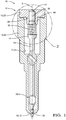
- a diesel fuel injector 10 comprises an injector holder assembly, a control valve and an injection nozzle 12 coaxially attached to each other and firmly held by an injector nut.
- Fuel injection is indirectly controlled by a solenoid valve which opens or closes a discharge channel allowing the hydraulic pressure to be lowered or increased in a control chamber 14 under the influence of which a valve member 16 moves between an open position PO, or injection, and a closed position PF, or no-injection.
- the nozzle 12 shown in axial section has a body 18 elongated along a main axis X and comprises a main member 20 and a top guide member 22, these two members 20, 22 together defining a bore 24 in which the valve member 16 , needle-shaped, is axially guided between a top guide 26 defined in the top guide member 22 and a bottom guide 28 defined towards the bottom of the main member 20.
- Said needle 16 is also permanently urged by a spring 30 compressed between a lower bearing face 32 integral with the needle and a high bearing face 34 integral with the upper guide member 22.
- the needle 16 has an elongated cylindrical body extending from a head 36 guided in the top guide 26 and partly defining said control chamber 14 to a point 38 defining a closure face 40 adapted to cooperate with a face of seat 42 defined in the body 18. Between the head 36 and the point 38, but closer to the head, the needle comprises an annular flange 44 surrounding the body of the needle and extending radially therefrom so as to define the lower bearing face 32 against which the spring 30 bears, said lower bearing face 32 facing the upper guide member 22.
- the needle In the closed position PF, the needle is in the lower position the shutter face 40 in sealed contact against the seat face 42 thus closing the fuel passage to the injection holes provided in the nozzle body and, in the open position PO the needle is raised, the closure face 40 being remote from the face of the seat 42 thus opening said passage.
- the upper guide member 22 is a cylindrical body complementarily arranged against the main member 20 and is provided with a turret forming an axial tubular extension 46 X extending from a lower face of said cylindrical body to a distal end forming said upper bearing face 34 of the spring. As shown, said turret 46 extends into an enlarged portion of bore 24 formed within the top of main member 20 of the nozzle body itself. The bore 24 continues axially in said turret 46 defining the face of the top guide 26 against which the head of the needle slides.
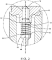
- the needle 16 moves at a high frequency and, to prevent rotation of the needle around the main axis X, the latter is maintained in its original angular orientation by means of the spring 30 whose ends are kept integral with the upper bearing face 32 for the upper end 48 of the spring and, with the lower bearing face 34 for the lower end 50 of the spring.
- Said spring 30 is a helical spring wound from a high turn forming the upper end 48 to a lower turn forming the lower end 50, the upper coil 48 and the lower coil 50 being erected so as to define at each of said ends a transverse face.
- a first washer 52 or upper washer
- a second bearing washer 54 or lower washer
- the compression of the spring associated with the annular surface of the washer makes it possible to increase the coefficient of friction and ensures the two ends of the spring are secured with on the one hand the upper guide member and on the other hand with the needle.
- the upper end 48 of the spring comprising the last upper coil, but which may also include the next neighboring coil, is inserted and wedged in a countersink 56 defined in the turret 46 and forming an annular groove around the periphery of the opening of the needle head guide bore.
- the top or turns 48 of the spring are inserted into said countersink 56 and wedge by friction against the outer face of the countersink while being supported against the upper bearing face 34 which is the transverse annular face forming the bottom of the countersink 56.
- the or the upper turns 48 of the spring are inserted and clipped into said counterbore 56, said outer face of the counterbore being provided with an annular bulge forming a notch reducing the section of said counterbore.
- the spring is forcefully inserted into the countersink 56, the very last coil of the spring is forced to retract to pass said notch and, when said last coil exceeds the notch, it relaxes again and gets stuck at the notch. counterbore bottom.
- figure 4 proposes to form a slight boss 60 slightly increasing the diameter of the body of the needle at the level of the collar 44 and to wedge said lower end 50 of the spring by inserting the lower turns 50 around this slight boss 60.
- the alternative of figure 5 proposes to machine the body of the needle at the level of the collar, so as to form an annular groove 58 surrounding the body of the needle, the groove of which the sides are, on the one hand, a boss slightly widening the body of the needle. the needle and, on the other hand, the collar 44 itself.
- said groove 58 the lower coil 50 of the spring gets stuck around the bottom of the groove and between these opposite sides.
- said boss is itself machined so as to form a conical face 62 which widens as it approaches the collar and facilitates the engagement of the lower turns 50 of the spring during assembly.
- figure 6 offers, similarly to the alternative of the figure 4 , to wedge said lower end 50 and the inside of the turns 50 against a slight boss 64 formed in contact with the collar.
- said boss 64 is conical slightly and gently increasing the diameter of the needle at the level of the collar 44 so as to facilitate the installation of the spring.
- any of the solutions proposed for blocking the upper end, bearing washer, counterbore, welding can be used with any of the solutions used to clamp the 'low end, boss, annular groove ...
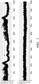
- the figure 7 shows two records of the flow of fuel injected as a function of time.
- the above recording corresponds to that of an injector 10 in which the needle 16 is free to rotate.
- the recording below is from the same injector after the needle is prevented from rotating.
Landscapes
- Engineering & Computer Science (AREA)
- Chemical & Material Sciences (AREA)
- Combustion & Propulsion (AREA)
- Mechanical Engineering (AREA)
- General Engineering & Computer Science (AREA)
- Fuel-Injection Apparatus (AREA)
Claims (10)
- Einspritzdüse (12) eines Dieselkraftstoffinjektors (10) für Verbrennungsmotoren, wobei die Düse (12) sich zwischen einem oberen Ende und einer Einspritzspitze entlang einer Hauptachse (X) erstreckt und einen Körper (18) aufweist, der mit einer Bohrung (24) versehen ist, in der eine ein Ventilglied bildende Nadel (16) geführt wird, wobei die Nadel (16) zwischen einer geschlossenen Position (PF), in der eine Fläche der Nadel (40) in Anschlag an einem Sitz (42) anliegt, der in dem Körper (18) in der Nähe der Einspritzspitze definiert ist, und einer offenen Position (PO), in der die Nadel (16) von dem Sitz entfernt liegt, axial verschiebbar ist, wobei die Düse (12) ferner eine Schraubenfeder (30) aufweist, die zwischen einer in dem Körper definierten oberen Lagerfläche (34) und einer die durch einen Bund (44) der Nadel definierten unteren Lagerfläche (32) zusammengedrückt wird, um die Nadel (16) dauerhaft in die geschlossene Position (PF) zu beaufschlagen,
dadurch gekennzeichnet, dass
die Schraubenfeder (30) ausgehend von einer unteren Windung (50), die fest mit der Nadel verbunden ist, bis zu einer oberen Windung (48), die fest mit dem Düsenkörper (18) verbunden ist, um die Nadel (16) herumgewickelt ist, um ein Verdrehen der Nadel in dem Körper zu verhindern, wobei der an den Bund (44) angrenzende Abschnitt der Nadel eine Erhebung (60, 64) definiert, um die herum die untere Windung der Feder (50) verspannt ist. - Einspritzdüse (12) nach dem vorhergehenden Anspruch, wobei die obere Windung (48) flächig an einer Ringfläche (34) des Körpers anliegt, wobei das Zusammendrücken der Feder verhindert, dass sich die obere Windung relativ zum Körper verdreht.
- Einspritzdüse (12) nach einem der vorhergehenden Ansprüche, wobei die obere Windung (48) mit dem Düsenkörper verschweißt ist, um zu verhindern, dass sich die obere Windung relativ zum Körper verdreht.
- Einspritzdüse (12) nach Anspruch 2, ferner enthaltend eine Lagerscheibe (52), die zwischen der oberen Windung (48) der Feder und der Ringfläche des Körpers (34) eingefügt ist.
- Einspritzdüse (12) nach Anspruch 1, wobei die obere Windung (48) in eine zwischen der Nadel und dem Injektorkörper definierte Senkung (56) eingepresst ist, wobei die obere Windung in die Senkung einrastet.
- Einspritzdüse (12) nach Anspruch 1, wobei die Erhebung (64) konisch ausgebildet ist, um das Einsetzen der Feder zu erleichtern und dann die untere Windung (50) zu verkeilen.
- Einspritzdüse (12) nach einem der Ansprüche 1 bis 5, wobei die untere Windung (50) flächig an einer Ringfläche (32) des Bundes anliegt, wobei das Zusammendrücken der Feder verhindert, dass sich die untere Windung relativ zur Nadel verdreht.
- Einspritzdüse (12) nach Anspruch 7, ferner umfassend eine Lagerscheibe (54), die zwischen der unteren Windung der Feder und der Ringfläche des Bundes eingefügt ist.
- Einspritzdüse (12) nach Anspruch 7, wobei der Abschnitt der Nadel, der an den Bund (44) angrenzt und um den herum die Feder gewickelt ist, eine ringförmige Nut (58) aufweist, in die die untere Windung (50) eingreift und zwischen den Flanken der Nut verkeilt ist.
- Dieselkraftstoffinjektor (10) für Verbrennungsmotoren, wobei der Injektor eine Einspritzdüse (12) nach einem der vorhergehenden Ansprüche aufweist.
Applications Claiming Priority (1)
| Application Number | Priority Date | Filing Date | Title |
|---|---|---|---|
| FR1756330A FR3068738B1 (fr) | 2017-07-05 | 2017-07-05 | Dispositif anti-rotation d'une aiguille de buse d'injection |
Publications (2)
| Publication Number | Publication Date |
|---|---|
| EP3425191A1 EP3425191A1 (de) | 2019-01-09 |
| EP3425191B1 true EP3425191B1 (de) | 2021-12-29 |
Family
ID=59811600
Family Applications (1)
| Application Number | Title | Priority Date | Filing Date |
|---|---|---|---|
| EP18181646.3A Active EP3425191B1 (de) | 2017-07-05 | 2018-07-04 | Antirotationsvorrichtung einer nadel einer injektionsdüse |
Country Status (2)
| Country | Link |
|---|---|
| EP (1) | EP3425191B1 (de) |
| FR (1) | FR3068738B1 (de) |
Family Cites Families (4)
| Publication number | Priority date | Publication date | Assignee | Title |
|---|---|---|---|---|
| DE3220398A1 (de) * | 1982-01-26 | 1983-07-28 | Robert Bosch Gmbh, 7000 Stuttgart | Kraftstoff-einspritzduese fuer brennkraftmaschinen |
| DE10048597A1 (de) * | 2000-09-30 | 2002-04-11 | Bosch Gmbh Robert | Kraftstoffeinspritzventil für Brennkraftmaschinen |
| EP1845254A1 (de) * | 2006-04-11 | 2007-10-17 | Siemens Aktiengesellschaft | Ventilanordnung |
| DE102015219441A1 (de) * | 2015-10-07 | 2017-04-13 | Continental Automotive Gmbh | Fluidinjektor zum Betreiben eines Kraftfahrzeugs und Verfahren zum Herstellen eines Fluidinjektors |
-
2017
- 2017-07-05 FR FR1756330A patent/FR3068738B1/fr active Active
-
2018
- 2018-07-04 EP EP18181646.3A patent/EP3425191B1/de active Active
Also Published As
| Publication number | Publication date |
|---|---|
| FR3068738A1 (fr) | 2019-01-11 |
| FR3068738B1 (fr) | 2019-12-27 |
| EP3425191A1 (de) | 2019-01-09 |
Similar Documents
| Publication | Publication Date | Title |
|---|---|---|
| EP1947385B1 (de) | Vorrichtung zur Kraftstoffeinspritzung in eine Strömungsmaschine | |
| EP3365548B1 (de) | Brennstoffeinspritzventil | |
| FR2702801A1 (fr) | Soupape d'injection de gaz pour l'injection de carburant sous forme gazeuse, notamment d'hydrogène, dans la chambre de combustion d'un moteur à combustion interne . | |
| FR2905638A1 (fr) | Embout pour le remplissage d'un reservoir | |
| FR2466691A1 (fr) | Soupape a commande electromagnetique | |
| FR2933748A1 (fr) | Dispositif injecteur de carburant | |
| FR2462573A1 (fr) | Injecteur a teton d'etranglement | |
| FR2816669A1 (fr) | Injecteur commande en pression avec une courbe d'injection optimisee en fonction de la course | |
| EP3425191B1 (de) | Antirotationsvorrichtung einer nadel einer injektionsdüse | |
| FR2534632A1 (fr) | Buse d'injection de carburant pour moteurs a combustion interne | |
| EP1312864B1 (de) | Kraftstoffdosierungsvorrichtung für die Einspritzdüse einer Turbomaschine | |
| FR2793526A1 (fr) | Systeme d'injection de carburant pour un moteur a combustion interne | |
| FR2982327A1 (fr) | Ensemble de bouchon pour vanne haute pression | |
| FR2772430A1 (fr) | Injecteur de carburant pour un moteur a combustion interne | |
| FR2726043A1 (fr) | Injecteur comportant une commande par soupape magnetique pour l'injection de carburant dans la chambre de combustion d'un moteur diesel | |
| FR2703424A1 (fr) | Soupape électromagnétique à trois voies. | |
| FR2465085A1 (fr) | Dispositif d'injection de carburant pour moteurs a combustion interne | |
| FR2766523A1 (fr) | Soupape injectrice de carburant a injection directe et pilotage par electrovanne pour moteur multicylindre | |
| FR2602279A1 (fr) | Soupape pour circuit de carburant de moteur a allumage par compression | |
| FR2715974A1 (fr) | Injecteur à commande par électrovanne pour moteur à combustion interne. | |
| FR2797914A1 (fr) | Soupape de commande d'injecteur de carburant | |
| FR2790301A1 (fr) | Soupape a section de passage variable | |
| FR2722540A1 (fr) | Buse d'injection de carburant | |
| EP1614894B1 (de) | Common Rail Einspritzsystem mit Druckwellendämpfungseinrichtung | |
| EP3489505B1 (de) | Ventilnadel eines injektors |
Legal Events
| Date | Code | Title | Description |
|---|---|---|---|
| PUAI | Public reference made under article 153(3) epc to a published international application that has entered the european phase |
Free format text: ORIGINAL CODE: 0009012 |
|
| STAA | Information on the status of an ep patent application or granted ep patent |
Free format text: STATUS: THE APPLICATION HAS BEEN PUBLISHED |
|
| AK | Designated contracting states |
Kind code of ref document: A1 Designated state(s): AL AT BE BG CH CY CZ DE DK EE ES FI FR GB GR HR HU IE IS IT LI LT LU LV MC MK MT NL NO PL PT RO RS SE SI SK SM TR |
|
| AX | Request for extension of the european patent |
Extension state: BA ME |
|
| STAA | Information on the status of an ep patent application or granted ep patent |
Free format text: STATUS: REQUEST FOR EXAMINATION WAS MADE |
|
| 17P | Request for examination filed |
Effective date: 20190709 |
|
| RBV | Designated contracting states (corrected) |
Designated state(s): AL AT BE BG CH CY CZ DE DK EE ES FI FR GB GR HR HU IE IS IT LI LT LU LV MC MK MT NL NO PL PT RO RS SE SI SK SM TR |
|
| STAA | Information on the status of an ep patent application or granted ep patent |
Free format text: STATUS: EXAMINATION IS IN PROGRESS |
|
| 17Q | First examination report despatched |
Effective date: 20201218 |
|
| GRAP | Despatch of communication of intention to grant a patent |
Free format text: ORIGINAL CODE: EPIDOSNIGR1 |
|
| STAA | Information on the status of an ep patent application or granted ep patent |
Free format text: STATUS: GRANT OF PATENT IS INTENDED |
|
| INTG | Intention to grant announced |
Effective date: 20210721 |
|
| GRAS | Grant fee paid |
Free format text: ORIGINAL CODE: EPIDOSNIGR3 |
|
| GRAA | (expected) grant |
Free format text: ORIGINAL CODE: 0009210 |
|
| STAA | Information on the status of an ep patent application or granted ep patent |
Free format text: STATUS: THE PATENT HAS BEEN GRANTED |
|
| AK | Designated contracting states |
Kind code of ref document: B1 Designated state(s): AL AT BE BG CH CY CZ DE DK EE ES FI FR GB GR HR HU IE IS IT LI LT LU LV MC MK MT NL NO PL PT RO RS SE SI SK SM TR |
|
| REG | Reference to a national code |
Ref country code: GB Ref legal event code: FG4D Free format text: NOT ENGLISH |
|
| REG | Reference to a national code |
Ref country code: CH Ref legal event code: EP |
|
| REG | Reference to a national code |
Ref country code: AT Ref legal event code: REF Ref document number: 1458866 Country of ref document: AT Kind code of ref document: T Effective date: 20220115 |
|
| REG | Reference to a national code |
Ref country code: IE Ref legal event code: FG4D Free format text: LANGUAGE OF EP DOCUMENT: FRENCH |
|
| REG | Reference to a national code |
Ref country code: DE Ref legal event code: R096 Ref document number: 602018028707 Country of ref document: DE |
|
| REG | Reference to a national code |
Ref country code: LT Ref legal event code: MG9D |
|
| PG25 | Lapsed in a contracting state [announced via postgrant information from national office to epo] |
Ref country code: RS Free format text: LAPSE BECAUSE OF FAILURE TO SUBMIT A TRANSLATION OF THE DESCRIPTION OR TO PAY THE FEE WITHIN THE PRESCRIBED TIME-LIMIT Effective date: 20211229 Ref country code: LT Free format text: LAPSE BECAUSE OF FAILURE TO SUBMIT A TRANSLATION OF THE DESCRIPTION OR TO PAY THE FEE WITHIN THE PRESCRIBED TIME-LIMIT Effective date: 20211229 Ref country code: FI Free format text: LAPSE BECAUSE OF FAILURE TO SUBMIT A TRANSLATION OF THE DESCRIPTION OR TO PAY THE FEE WITHIN THE PRESCRIBED TIME-LIMIT Effective date: 20211229 Ref country code: BG Free format text: LAPSE BECAUSE OF FAILURE TO SUBMIT A TRANSLATION OF THE DESCRIPTION OR TO PAY THE FEE WITHIN THE PRESCRIBED TIME-LIMIT Effective date: 20220329 |
|
| REG | Reference to a national code |
Ref country code: NL Ref legal event code: MP Effective date: 20211229 |
|
| REG | Reference to a national code |
Ref country code: AT Ref legal event code: MK05 Ref document number: 1458866 Country of ref document: AT Kind code of ref document: T Effective date: 20211229 |
|
| PG25 | Lapsed in a contracting state [announced via postgrant information from national office to epo] |
Ref country code: SE Free format text: LAPSE BECAUSE OF FAILURE TO SUBMIT A TRANSLATION OF THE DESCRIPTION OR TO PAY THE FEE WITHIN THE PRESCRIBED TIME-LIMIT Effective date: 20211229 Ref country code: NO Free format text: LAPSE BECAUSE OF FAILURE TO SUBMIT A TRANSLATION OF THE DESCRIPTION OR TO PAY THE FEE WITHIN THE PRESCRIBED TIME-LIMIT Effective date: 20220329 Ref country code: LV Free format text: LAPSE BECAUSE OF FAILURE TO SUBMIT A TRANSLATION OF THE DESCRIPTION OR TO PAY THE FEE WITHIN THE PRESCRIBED TIME-LIMIT Effective date: 20211229 Ref country code: HR Free format text: LAPSE BECAUSE OF FAILURE TO SUBMIT A TRANSLATION OF THE DESCRIPTION OR TO PAY THE FEE WITHIN THE PRESCRIBED TIME-LIMIT Effective date: 20211229 Ref country code: GR Free format text: LAPSE BECAUSE OF FAILURE TO SUBMIT A TRANSLATION OF THE DESCRIPTION OR TO PAY THE FEE WITHIN THE PRESCRIBED TIME-LIMIT Effective date: 20220330 |
|
| PG25 | Lapsed in a contracting state [announced via postgrant information from national office to epo] |
Ref country code: NL Free format text: LAPSE BECAUSE OF FAILURE TO SUBMIT A TRANSLATION OF THE DESCRIPTION OR TO PAY THE FEE WITHIN THE PRESCRIBED TIME-LIMIT Effective date: 20211229 |
|
| PG25 | Lapsed in a contracting state [announced via postgrant information from national office to epo] |
Ref country code: SM Free format text: LAPSE BECAUSE OF FAILURE TO SUBMIT A TRANSLATION OF THE DESCRIPTION OR TO PAY THE FEE WITHIN THE PRESCRIBED TIME-LIMIT Effective date: 20211229 Ref country code: SK Free format text: LAPSE BECAUSE OF FAILURE TO SUBMIT A TRANSLATION OF THE DESCRIPTION OR TO PAY THE FEE WITHIN THE PRESCRIBED TIME-LIMIT Effective date: 20211229 Ref country code: RO Free format text: LAPSE BECAUSE OF FAILURE TO SUBMIT A TRANSLATION OF THE DESCRIPTION OR TO PAY THE FEE WITHIN THE PRESCRIBED TIME-LIMIT Effective date: 20211229 Ref country code: PT Free format text: LAPSE BECAUSE OF FAILURE TO SUBMIT A TRANSLATION OF THE DESCRIPTION OR TO PAY THE FEE WITHIN THE PRESCRIBED TIME-LIMIT Effective date: 20220429 Ref country code: ES Free format text: LAPSE BECAUSE OF FAILURE TO SUBMIT A TRANSLATION OF THE DESCRIPTION OR TO PAY THE FEE WITHIN THE PRESCRIBED TIME-LIMIT Effective date: 20211229 Ref country code: EE Free format text: LAPSE BECAUSE OF FAILURE TO SUBMIT A TRANSLATION OF THE DESCRIPTION OR TO PAY THE FEE WITHIN THE PRESCRIBED TIME-LIMIT Effective date: 20211229 Ref country code: CZ Free format text: LAPSE BECAUSE OF FAILURE TO SUBMIT A TRANSLATION OF THE DESCRIPTION OR TO PAY THE FEE WITHIN THE PRESCRIBED TIME-LIMIT Effective date: 20211229 |
|
| PG25 | Lapsed in a contracting state [announced via postgrant information from national office to epo] |
Ref country code: PL Free format text: LAPSE BECAUSE OF FAILURE TO SUBMIT A TRANSLATION OF THE DESCRIPTION OR TO PAY THE FEE WITHIN THE PRESCRIBED TIME-LIMIT Effective date: 20211229 Ref country code: AT Free format text: LAPSE BECAUSE OF FAILURE TO SUBMIT A TRANSLATION OF THE DESCRIPTION OR TO PAY THE FEE WITHIN THE PRESCRIBED TIME-LIMIT Effective date: 20211229 |
|
| PG25 | Lapsed in a contracting state [announced via postgrant information from national office to epo] |
Ref country code: IS Free format text: LAPSE BECAUSE OF FAILURE TO SUBMIT A TRANSLATION OF THE DESCRIPTION OR TO PAY THE FEE WITHIN THE PRESCRIBED TIME-LIMIT Effective date: 20220429 |
|
| REG | Reference to a national code |
Ref country code: DE Ref legal event code: R097 Ref document number: 602018028707 Country of ref document: DE |
|
| PG25 | Lapsed in a contracting state [announced via postgrant information from national office to epo] |
Ref country code: DK Free format text: LAPSE BECAUSE OF FAILURE TO SUBMIT A TRANSLATION OF THE DESCRIPTION OR TO PAY THE FEE WITHIN THE PRESCRIBED TIME-LIMIT Effective date: 20211229 Ref country code: AL Free format text: LAPSE BECAUSE OF FAILURE TO SUBMIT A TRANSLATION OF THE DESCRIPTION OR TO PAY THE FEE WITHIN THE PRESCRIBED TIME-LIMIT Effective date: 20211229 |
|
| PLBE | No opposition filed within time limit |
Free format text: ORIGINAL CODE: 0009261 |
|
| STAA | Information on the status of an ep patent application or granted ep patent |
Free format text: STATUS: NO OPPOSITION FILED WITHIN TIME LIMIT |
|
| 26N | No opposition filed |
Effective date: 20220930 |
|
| PG25 | Lapsed in a contracting state [announced via postgrant information from national office to epo] |
Ref country code: SI Free format text: LAPSE BECAUSE OF FAILURE TO SUBMIT A TRANSLATION OF THE DESCRIPTION OR TO PAY THE FEE WITHIN THE PRESCRIBED TIME-LIMIT Effective date: 20211229 Ref country code: MC Free format text: LAPSE BECAUSE OF FAILURE TO SUBMIT A TRANSLATION OF THE DESCRIPTION OR TO PAY THE FEE WITHIN THE PRESCRIBED TIME-LIMIT Effective date: 20211229 |
|
| REG | Reference to a national code |
Ref country code: CH Ref legal event code: PL |
|
| REG | Reference to a national code |
Ref country code: BE Ref legal event code: MM Effective date: 20220731 |
|
| PG25 | Lapsed in a contracting state [announced via postgrant information from national office to epo] |
Ref country code: LU Free format text: LAPSE BECAUSE OF NON-PAYMENT OF DUE FEES Effective date: 20220704 Ref country code: LI Free format text: LAPSE BECAUSE OF NON-PAYMENT OF DUE FEES Effective date: 20220731 Ref country code: CH Free format text: LAPSE BECAUSE OF NON-PAYMENT OF DUE FEES Effective date: 20220731 |
|
| PG25 | Lapsed in a contracting state [announced via postgrant information from national office to epo] |
Ref country code: IT Free format text: LAPSE BECAUSE OF FAILURE TO SUBMIT A TRANSLATION OF THE DESCRIPTION OR TO PAY THE FEE WITHIN THE PRESCRIBED TIME-LIMIT Effective date: 20211229 Ref country code: BE Free format text: LAPSE BECAUSE OF NON-PAYMENT OF DUE FEES Effective date: 20220731 |
|
| P01 | Opt-out of the competence of the unified patent court (upc) registered |
Effective date: 20230327 |
|
| PG25 | Lapsed in a contracting state [announced via postgrant information from national office to epo] |
Ref country code: IE Free format text: LAPSE BECAUSE OF NON-PAYMENT OF DUE FEES Effective date: 20220704 |
|
| PG25 | Lapsed in a contracting state [announced via postgrant information from national office to epo] |
Ref country code: HU Free format text: LAPSE BECAUSE OF FAILURE TO SUBMIT A TRANSLATION OF THE DESCRIPTION OR TO PAY THE FEE WITHIN THE PRESCRIBED TIME-LIMIT; INVALID AB INITIO Effective date: 20180704 |
|
| REG | Reference to a national code |
Ref country code: DE Ref legal event code: R081 Ref document number: 602018028707 Country of ref document: DE Owner name: PHINIA DELPHI LUXEMBOURG SARL, LU Free format text: FORMER OWNER: DELPHI TECHNOLOGIES IP LIMITED, SAINT MICHAEL, BB |
|
| PG25 | Lapsed in a contracting state [announced via postgrant information from national office to epo] |
Ref country code: MK Free format text: LAPSE BECAUSE OF FAILURE TO SUBMIT A TRANSLATION OF THE DESCRIPTION OR TO PAY THE FEE WITHIN THE PRESCRIBED TIME-LIMIT Effective date: 20211229 Ref country code: CY Free format text: LAPSE BECAUSE OF FAILURE TO SUBMIT A TRANSLATION OF THE DESCRIPTION OR TO PAY THE FEE WITHIN THE PRESCRIBED TIME-LIMIT Effective date: 20211229 |
|
| REG | Reference to a national code |
Ref country code: GB Ref legal event code: 732E Free format text: REGISTERED BETWEEN 20240516 AND 20240522 |
|
| PG25 | Lapsed in a contracting state [announced via postgrant information from national office to epo] |
Ref country code: MT Free format text: LAPSE BECAUSE OF FAILURE TO SUBMIT A TRANSLATION OF THE DESCRIPTION OR TO PAY THE FEE WITHIN THE PRESCRIBED TIME-LIMIT Effective date: 20211229 |
|
| PGFP | Annual fee paid to national office [announced via postgrant information from national office to epo] |
Ref country code: GB Payment date: 20250612 Year of fee payment: 8 |
|
| PGFP | Annual fee paid to national office [announced via postgrant information from national office to epo] |
Ref country code: FR Payment date: 20250612 Year of fee payment: 8 |
|
| PGFP | Annual fee paid to national office [announced via postgrant information from national office to epo] |
Ref country code: DE Payment date: 20250616 Year of fee payment: 8 |
|
| PG25 | Lapsed in a contracting state [announced via postgrant information from national office to epo] |
Ref country code: TR Free format text: LAPSE BECAUSE OF FAILURE TO SUBMIT A TRANSLATION OF THE DESCRIPTION OR TO PAY THE FEE WITHIN THE PRESCRIBED TIME-LIMIT Effective date: 20211229 |