EP3425179A1 - Construction machine - Google Patents
Construction machine Download PDFInfo
- Publication number
- EP3425179A1 EP3425179A1 EP16892648.3A EP16892648A EP3425179A1 EP 3425179 A1 EP3425179 A1 EP 3425179A1 EP 16892648 A EP16892648 A EP 16892648A EP 3425179 A1 EP3425179 A1 EP 3425179A1
- Authority
- EP
- European Patent Office
- Prior art keywords
- urea water
- pipeline
- heater
- water pump
- water tank
- Prior art date
- Legal status (The legal status is an assumption and is not a legal conclusion. Google has not performed a legal analysis and makes no representation as to the accuracy of the status listed.)
- Withdrawn
Links
Images


Classifications
-
- F—MECHANICAL ENGINEERING; LIGHTING; HEATING; WEAPONS; BLASTING
- F01—MACHINES OR ENGINES IN GENERAL; ENGINE PLANTS IN GENERAL; STEAM ENGINES
- F01N—GAS-FLOW SILENCERS OR EXHAUST APPARATUS FOR MACHINES OR ENGINES IN GENERAL; GAS-FLOW SILENCERS OR EXHAUST APPARATUS FOR INTERNAL-COMBUSTION ENGINES
- F01N3/00—Exhaust or silencing apparatus having means for purifying, rendering innocuous, or otherwise treating exhaust
- F01N3/08—Exhaust or silencing apparatus having means for purifying, rendering innocuous, or otherwise treating exhaust for rendering innocuous
- F01N3/10—Exhaust or silencing apparatus having means for purifying, rendering innocuous, or otherwise treating exhaust for rendering innocuous by thermal or catalytic conversion of noxious components of exhaust
- F01N3/18—Exhaust or silencing apparatus having means for purifying, rendering innocuous, or otherwise treating exhaust for rendering innocuous by thermal or catalytic conversion of noxious components of exhaust characterised by methods of operation; Control
- F01N3/20—Exhaust or silencing apparatus having means for purifying, rendering innocuous, or otherwise treating exhaust for rendering innocuous by thermal or catalytic conversion of noxious components of exhaust characterised by methods of operation; Control specially adapted for catalytic conversion
- F01N3/2006—Periodically heating or cooling catalytic reactors, e.g. at cold starting or overheating
- F01N3/2013—Periodically heating or cooling catalytic reactors, e.g. at cold starting or overheating using electric or magnetic heating means
-
- B—PERFORMING OPERATIONS; TRANSPORTING
- B01—PHYSICAL OR CHEMICAL PROCESSES OR APPARATUS IN GENERAL
- B01D—SEPARATION
- B01D53/00—Separation of gases or vapours; Recovering vapours of volatile solvents from gases; Chemical or biological purification of waste gases, e.g. engine exhaust gases, smoke, fumes, flue gases, aerosols
- B01D53/34—Chemical or biological purification of waste gases
- B01D53/92—Chemical or biological purification of waste gases of engine exhaust gases
- B01D53/94—Chemical or biological purification of waste gases of engine exhaust gases by catalytic processes
-
- B—PERFORMING OPERATIONS; TRANSPORTING
- B01—PHYSICAL OR CHEMICAL PROCESSES OR APPARATUS IN GENERAL
- B01D—SEPARATION
- B01D53/00—Separation of gases or vapours; Recovering vapours of volatile solvents from gases; Chemical or biological purification of waste gases, e.g. engine exhaust gases, smoke, fumes, flue gases, aerosols
- B01D53/34—Chemical or biological purification of waste gases
- B01D53/92—Chemical or biological purification of waste gases of engine exhaust gases
- B01D53/94—Chemical or biological purification of waste gases of engine exhaust gases by catalytic processes
- B01D53/9404—Removing only nitrogen compounds
- B01D53/9409—Nitrogen oxides
- B01D53/9413—Processes characterised by a specific catalyst
- B01D53/9418—Processes characterised by a specific catalyst for removing nitrogen oxides by selective catalytic reduction [SCR] using a reducing agent in a lean exhaust gas
-
- E—FIXED CONSTRUCTIONS
- E02—HYDRAULIC ENGINEERING; FOUNDATIONS; SOIL SHIFTING
- E02F—DREDGING; SOIL-SHIFTING
- E02F9/00—Component parts of dredgers or soil-shifting machines, not restricted to one of the kinds covered by groups E02F3/00 - E02F7/00
- E02F9/08—Superstructures; Supports for superstructures
- E02F9/0858—Arrangement of component parts installed on superstructures not otherwise provided for, e.g. electric components, fenders, air-conditioning units
- E02F9/0866—Engine compartment, e.g. heat exchangers, exhaust filters, cooling devices, silencers, mufflers, position of hydraulic pumps in the engine compartment
-
- E—FIXED CONSTRUCTIONS
- E02—HYDRAULIC ENGINEERING; FOUNDATIONS; SOIL SHIFTING
- E02F—DREDGING; SOIL-SHIFTING
- E02F9/00—Component parts of dredgers or soil-shifting machines, not restricted to one of the kinds covered by groups E02F3/00 - E02F7/00
- E02F9/08—Superstructures; Supports for superstructures
- E02F9/0858—Arrangement of component parts installed on superstructures not otherwise provided for, e.g. electric components, fenders, air-conditioning units
- E02F9/0883—Tanks, e.g. oil tank, urea tank, fuel tank
-
- F—MECHANICAL ENGINEERING; LIGHTING; HEATING; WEAPONS; BLASTING
- F01—MACHINES OR ENGINES IN GENERAL; ENGINE PLANTS IN GENERAL; STEAM ENGINES
- F01N—GAS-FLOW SILENCERS OR EXHAUST APPARATUS FOR MACHINES OR ENGINES IN GENERAL; GAS-FLOW SILENCERS OR EXHAUST APPARATUS FOR INTERNAL-COMBUSTION ENGINES
- F01N3/00—Exhaust or silencing apparatus having means for purifying, rendering innocuous, or otherwise treating exhaust
- F01N3/08—Exhaust or silencing apparatus having means for purifying, rendering innocuous, or otherwise treating exhaust for rendering innocuous
- F01N3/10—Exhaust or silencing apparatus having means for purifying, rendering innocuous, or otherwise treating exhaust for rendering innocuous by thermal or catalytic conversion of noxious components of exhaust
- F01N3/18—Exhaust or silencing apparatus having means for purifying, rendering innocuous, or otherwise treating exhaust for rendering innocuous by thermal or catalytic conversion of noxious components of exhaust characterised by methods of operation; Control
- F01N3/20—Exhaust or silencing apparatus having means for purifying, rendering innocuous, or otherwise treating exhaust for rendering innocuous by thermal or catalytic conversion of noxious components of exhaust characterised by methods of operation; Control specially adapted for catalytic conversion
- F01N3/206—Adding periodically or continuously substances to exhaust gases for promoting purification, e.g. catalytic material in liquid form, NOx reducing agents
-
- F—MECHANICAL ENGINEERING; LIGHTING; HEATING; WEAPONS; BLASTING
- F01—MACHINES OR ENGINES IN GENERAL; ENGINE PLANTS IN GENERAL; STEAM ENGINES
- F01N—GAS-FLOW SILENCERS OR EXHAUST APPARATUS FOR MACHINES OR ENGINES IN GENERAL; GAS-FLOW SILENCERS OR EXHAUST APPARATUS FOR INTERNAL-COMBUSTION ENGINES
- F01N3/00—Exhaust or silencing apparatus having means for purifying, rendering innocuous, or otherwise treating exhaust
- F01N3/08—Exhaust or silencing apparatus having means for purifying, rendering innocuous, or otherwise treating exhaust for rendering innocuous
- F01N3/10—Exhaust or silencing apparatus having means for purifying, rendering innocuous, or otherwise treating exhaust for rendering innocuous by thermal or catalytic conversion of noxious components of exhaust
- F01N3/18—Exhaust or silencing apparatus having means for purifying, rendering innocuous, or otherwise treating exhaust for rendering innocuous by thermal or catalytic conversion of noxious components of exhaust characterised by methods of operation; Control
- F01N3/20—Exhaust or silencing apparatus having means for purifying, rendering innocuous, or otherwise treating exhaust for rendering innocuous by thermal or catalytic conversion of noxious components of exhaust characterised by methods of operation; Control specially adapted for catalytic conversion
- F01N3/206—Adding periodically or continuously substances to exhaust gases for promoting purification, e.g. catalytic material in liquid form, NOx reducing agents
- F01N3/2066—Selective catalytic reduction [SCR]
-
- B—PERFORMING OPERATIONS; TRANSPORTING
- B01—PHYSICAL OR CHEMICAL PROCESSES OR APPARATUS IN GENERAL
- B01D—SEPARATION
- B01D53/00—Separation of gases or vapours; Recovering vapours of volatile solvents from gases; Chemical or biological purification of waste gases, e.g. engine exhaust gases, smoke, fumes, flue gases, aerosols
- B01D53/34—Chemical or biological purification of waste gases
- B01D53/92—Chemical or biological purification of waste gases of engine exhaust gases
- B01D53/94—Chemical or biological purification of waste gases of engine exhaust gases by catalytic processes
- B01D53/9404—Removing only nitrogen compounds
- B01D53/9409—Nitrogen oxides
-
- B—PERFORMING OPERATIONS; TRANSPORTING
- B01—PHYSICAL OR CHEMICAL PROCESSES OR APPARATUS IN GENERAL
- B01D—SEPARATION
- B01D53/00—Separation of gases or vapours; Recovering vapours of volatile solvents from gases; Chemical or biological purification of waste gases, e.g. engine exhaust gases, smoke, fumes, flue gases, aerosols
- B01D53/34—Chemical or biological purification of waste gases
- B01D53/92—Chemical or biological purification of waste gases of engine exhaust gases
- B01D53/94—Chemical or biological purification of waste gases of engine exhaust gases by catalytic processes
- B01D53/9459—Removing one or more of nitrogen oxides, carbon monoxide, or hydrocarbons by multiple successive catalytic functions; systems with more than one different function, e.g. zone coated catalysts
- B01D53/9477—Removing one or more of nitrogen oxides, carbon monoxide, or hydrocarbons by multiple successive catalytic functions; systems with more than one different function, e.g. zone coated catalysts with catalysts positioned on separate bricks, e.g. exhaust systems
-
- F—MECHANICAL ENGINEERING; LIGHTING; HEATING; WEAPONS; BLASTING
- F01—MACHINES OR ENGINES IN GENERAL; ENGINE PLANTS IN GENERAL; STEAM ENGINES
- F01N—GAS-FLOW SILENCERS OR EXHAUST APPARATUS FOR MACHINES OR ENGINES IN GENERAL; GAS-FLOW SILENCERS OR EXHAUST APPARATUS FOR INTERNAL-COMBUSTION ENGINES
- F01N2590/00—Exhaust or silencing apparatus adapted to particular use, e.g. for military applications, airplanes, submarines
- F01N2590/08—Exhaust or silencing apparatus adapted to particular use, e.g. for military applications, airplanes, submarines for heavy duty applications, e.g. trucks, buses, tractors, locomotives
-
- F—MECHANICAL ENGINEERING; LIGHTING; HEATING; WEAPONS; BLASTING
- F01—MACHINES OR ENGINES IN GENERAL; ENGINE PLANTS IN GENERAL; STEAM ENGINES
- F01N—GAS-FLOW SILENCERS OR EXHAUST APPARATUS FOR MACHINES OR ENGINES IN GENERAL; GAS-FLOW SILENCERS OR EXHAUST APPARATUS FOR INTERNAL-COMBUSTION ENGINES
- F01N2610/00—Adding substances to exhaust gases
- F01N2610/02—Adding substances to exhaust gases the substance being ammonia or urea
-
- F—MECHANICAL ENGINEERING; LIGHTING; HEATING; WEAPONS; BLASTING
- F01—MACHINES OR ENGINES IN GENERAL; ENGINE PLANTS IN GENERAL; STEAM ENGINES
- F01N—GAS-FLOW SILENCERS OR EXHAUST APPARATUS FOR MACHINES OR ENGINES IN GENERAL; GAS-FLOW SILENCERS OR EXHAUST APPARATUS FOR INTERNAL-COMBUSTION ENGINES
- F01N2610/00—Adding substances to exhaust gases
- F01N2610/10—Adding substances to exhaust gases the substance being heated, e.g. by heating tank or supply line of the added substance
-
- F—MECHANICAL ENGINEERING; LIGHTING; HEATING; WEAPONS; BLASTING
- F01—MACHINES OR ENGINES IN GENERAL; ENGINE PLANTS IN GENERAL; STEAM ENGINES
- F01N—GAS-FLOW SILENCERS OR EXHAUST APPARATUS FOR MACHINES OR ENGINES IN GENERAL; GAS-FLOW SILENCERS OR EXHAUST APPARATUS FOR INTERNAL-COMBUSTION ENGINES
- F01N2610/00—Adding substances to exhaust gases
- F01N2610/10—Adding substances to exhaust gases the substance being heated, e.g. by heating tank or supply line of the added substance
- F01N2610/105—Control thereof
-
- F—MECHANICAL ENGINEERING; LIGHTING; HEATING; WEAPONS; BLASTING
- F01—MACHINES OR ENGINES IN GENERAL; ENGINE PLANTS IN GENERAL; STEAM ENGINES
- F01N—GAS-FLOW SILENCERS OR EXHAUST APPARATUS FOR MACHINES OR ENGINES IN GENERAL; GAS-FLOW SILENCERS OR EXHAUST APPARATUS FOR INTERNAL-COMBUSTION ENGINES
- F01N2610/00—Adding substances to exhaust gases
- F01N2610/14—Arrangements for the supply of substances, e.g. conduits
-
- F—MECHANICAL ENGINEERING; LIGHTING; HEATING; WEAPONS; BLASTING
- F01—MACHINES OR ENGINES IN GENERAL; ENGINE PLANTS IN GENERAL; STEAM ENGINES
- F01N—GAS-FLOW SILENCERS OR EXHAUST APPARATUS FOR MACHINES OR ENGINES IN GENERAL; GAS-FLOW SILENCERS OR EXHAUST APPARATUS FOR INTERNAL-COMBUSTION ENGINES
- F01N2610/00—Adding substances to exhaust gases
- F01N2610/14—Arrangements for the supply of substances, e.g. conduits
- F01N2610/1406—Storage means for substances, e.g. tanks or reservoirs
-
- F—MECHANICAL ENGINEERING; LIGHTING; HEATING; WEAPONS; BLASTING
- F01—MACHINES OR ENGINES IN GENERAL; ENGINE PLANTS IN GENERAL; STEAM ENGINES
- F01N—GAS-FLOW SILENCERS OR EXHAUST APPARATUS FOR MACHINES OR ENGINES IN GENERAL; GAS-FLOW SILENCERS OR EXHAUST APPARATUS FOR INTERNAL-COMBUSTION ENGINES
- F01N2610/00—Adding substances to exhaust gases
- F01N2610/14—Arrangements for the supply of substances, e.g. conduits
- F01N2610/1433—Pumps
-
- F—MECHANICAL ENGINEERING; LIGHTING; HEATING; WEAPONS; BLASTING
- F01—MACHINES OR ENGINES IN GENERAL; ENGINE PLANTS IN GENERAL; STEAM ENGINES
- F01N—GAS-FLOW SILENCERS OR EXHAUST APPARATUS FOR MACHINES OR ENGINES IN GENERAL; GAS-FLOW SILENCERS OR EXHAUST APPARATUS FOR INTERNAL-COMBUSTION ENGINES
- F01N2610/00—Adding substances to exhaust gases
- F01N2610/14—Arrangements for the supply of substances, e.g. conduits
- F01N2610/1453—Sprayers or atomisers; Arrangement thereof in the exhaust apparatus
-
- F—MECHANICAL ENGINEERING; LIGHTING; HEATING; WEAPONS; BLASTING
- F01—MACHINES OR ENGINES IN GENERAL; ENGINE PLANTS IN GENERAL; STEAM ENGINES
- F01N—GAS-FLOW SILENCERS OR EXHAUST APPARATUS FOR MACHINES OR ENGINES IN GENERAL; GAS-FLOW SILENCERS OR EXHAUST APPARATUS FOR INTERNAL-COMBUSTION ENGINES
- F01N2610/00—Adding substances to exhaust gases
- F01N2610/14—Arrangements for the supply of substances, e.g. conduits
- F01N2610/1473—Overflow or return means for the substances, e.g. conduits or valves for the return path
-
- F—MECHANICAL ENGINEERING; LIGHTING; HEATING; WEAPONS; BLASTING
- F01—MACHINES OR ENGINES IN GENERAL; ENGINE PLANTS IN GENERAL; STEAM ENGINES
- F01N—GAS-FLOW SILENCERS OR EXHAUST APPARATUS FOR MACHINES OR ENGINES IN GENERAL; GAS-FLOW SILENCERS OR EXHAUST APPARATUS FOR INTERNAL-COMBUSTION ENGINES
- F01N2610/00—Adding substances to exhaust gases
- F01N2610/14—Arrangements for the supply of substances, e.g. conduits
- F01N2610/1486—Means to prevent the substance from freezing
-
- Y—GENERAL TAGGING OF NEW TECHNOLOGICAL DEVELOPMENTS; GENERAL TAGGING OF CROSS-SECTIONAL TECHNOLOGIES SPANNING OVER SEVERAL SECTIONS OF THE IPC; TECHNICAL SUBJECTS COVERED BY FORMER USPC CROSS-REFERENCE ART COLLECTIONS [XRACs] AND DIGESTS
- Y02—TECHNOLOGIES OR APPLICATIONS FOR MITIGATION OR ADAPTATION AGAINST CLIMATE CHANGE
- Y02A—TECHNOLOGIES FOR ADAPTATION TO CLIMATE CHANGE
- Y02A50/00—TECHNOLOGIES FOR ADAPTATION TO CLIMATE CHANGE in human health protection, e.g. against extreme weather
- Y02A50/20—Air quality improvement or preservation, e.g. vehicle emission control or emission reduction by using catalytic converters
-
- Y—GENERAL TAGGING OF NEW TECHNOLOGICAL DEVELOPMENTS; GENERAL TAGGING OF CROSS-SECTIONAL TECHNOLOGIES SPANNING OVER SEVERAL SECTIONS OF THE IPC; TECHNICAL SUBJECTS COVERED BY FORMER USPC CROSS-REFERENCE ART COLLECTIONS [XRACs] AND DIGESTS
- Y02—TECHNOLOGIES OR APPLICATIONS FOR MITIGATION OR ADAPTATION AGAINST CLIMATE CHANGE
- Y02T—CLIMATE CHANGE MITIGATION TECHNOLOGIES RELATED TO TRANSPORTATION
- Y02T10/00—Road transport of goods or passengers
- Y02T10/10—Internal combustion engine [ICE] based vehicles
- Y02T10/12—Improving ICE efficiencies
Definitions
- the present invention relates to a construction machine such as a hydraulic excavator and the like with a urea water tank that stores urea water and a urea water pump that supplies the urea water in the urea water tank to an exhaust gas purifying device being mounted.
- the hydraulic excavator as a representative example of the construction machine comprising: an automotive vehicle body; an engine that is mounted on the vehicle body; an exhaust gas purifying device that is connected to an exhaust pipe of the engine and is provided with a urea selective reduction catalyst that removes a nitrogen oxide in an exhaust gas; a urea water injection valve that is provided in the exhaust gas purifying device and injects urea water that is a reducing agent to the upstream side of the urea selective reduction catalyst; a urea water tank that stores the urea water to be supplied to the urea water injection valve; a urea water pump that supplies the urea water that is stored in the urea water tank toward the urea water injection valve.
- the urea water tank and the urea water pump are connected to each other via a suction pipeline through which the urea water that is sucked from the urea water tank toward the urea water pump flows and a return pipeline through which the urea water that is returned from the urea water pump toward the urea water tank flows.
- the urea water pump and the urea water injection valve are connected to each other via a supply pipeline through which the urea water that is supplied toward the urea water injection valve by the urea water pump flows.
- a warming pipeline through which engine cooling water warmed by an engine flows is provided in the urea water tank and suppresses (defrosts) freezing of the urea water stored in the urea water tank (Patent Document 1).
- the one that uses the engine cooling water warmed by the engine and the one that uses a heater such as a heating wire and the like are known as the ones that suppress freezing of the urea water in the suction pipeline, the return pipeline, the supply pipeline.
- Patent Document 1 Japanese Patent Application Laid-Open No. 2012-225304 A
- the engine cooling water in a case where the engine cooling water is used for defrosting the urea water, it is necessary to drive the engine. In addition, since a sufficient time is necessary to warm the engine cooling water after driving of the engine, there is a possibility that the time may be taken to defrost the urea water.
- the heater such as the heating wire and the like is excellent in defrosting performance in comparison with a case of using the engine cooling water. However, since power consumption is increased, a large-capacity generator becomes necessary. Further, since the heating wire, a connector and the like become newly necessary, there is a possibility that a cost may be increased.
- the present invention is characterized in that a construction machine comprising: an automotive vehicle body; an engine that is mounted on the vehicle body; an exhaust gas purifying device that is connected to an exhaust pipe of the engine and includes a urea selective reduction catalyst that removes a nitrogen oxide in an exhaust gas; a urea water injection valve that is provided in the exhaust gas purifying device and injects urea water that is a reducing agent to the upstream side of the urea selective reduction catalyst; a urea water tank that stores the urea water to be supplied to the urea water injection valve; a urea water pump that supplies the urea water that is stored in the urea water tank toward the urea water injection valve; a suction pipeline that is provided so as to connect the urea water tank and the urea water pump to each other and through which the urea water that is sucked from the urea water tank toward the urea water pump flows; a return pipeline that is provided so as to connect the urea water pump and the urea water tank
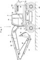
- a hydraulic excavator 1 is configured by an automotive wheel-type lower traveling structure 2 having left and right front wheels 2A and left and right rear wheels 2B, an upper revolving structure 3 that is rotatably mounted on the lower traveling structure 2, and a front device 4 that is tiltably provided on the upper revolving structure 3.
- the wheel-type hydraulic excavator 1 includes the lower traveling structure 2 and the upper revolving structure 3 and thereby a vehicle body of the present invention is configured.
- the front device 4 is configured by a boom 4A, an arm 4B, a bucket 4C, a boom cylinder 4D, an arm cylinder 4E, a bucket cylinder 4F and the like.
- a foot part 4G of the boom 4A is rotatably attached to an intermediate part in a left-right direction on the front side of a revolving frame 5 that will be described later as shown in Fig. 2 .
- the revolving frame 5 is the one that configures a support structure body of the upper revolving structure 3 and is rotatably mounted on the lower traveling structure 2 with the foot part 4G of the front device 4 being attached to the front side thereof.
- the revolving frame 5 is configured by including a bottom plate 5A that is composed of a thick steel plate and the like that extends in a front-rear direction, a left vertical plate 5B and a right vertical plate 5C that are installed upright on the bottom plate 5A and extending in the front-rear direction with a predetermined interval in the left-right direction, a left side frame 5D and a right side frame 5E that are disposed on the left and the right of the respective vertical plates 5B, 5C with an interval and extending in the front-rear direction, and a plurality of extension beams 5F that extend from the bottom plate 5A, each of the vertical plates 5B, 5C in the left-right direction respectively and support the left and right side frames 5D, 5E at leading end parts thereof
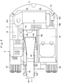
- the counterweight 6 is provided on rear ends of the left and right vertical plates 5B, 5C that configure the revolving frame 5. This counterweight 6 acts as a weight balance to the front device 4. A rear surface of the counterweight 6 is formed into a substantially arc shape centering on a revolving center of the upper revolving structure 3 (see Fig. 2 ).
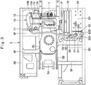
- An engine 7 is located on the front side of the counterweight 6 and is provided on the rear part of the revolving frame 5. This engine 7 is mounted on horizontally placed state where it extends in the left-right direction as shown in Fig. 3 .
- a cooling fan 8 that sucks outdoor air as cooling air is disposed on the left side that is the one side in the left-right direction of the engine 7.
- a hydraulic pump (not shown) is disposed on the right side that is the other side in the left-right direction of the engine 7, located on the lower side of an exhaust gas purifying device 10 that will be described later.
- the hydraulic pump is adapted to supply pressurized oil toward various kinds of hydraulic actuators provided in the upper revolving structure 3, the front device 4 by being driven by the engine 7.
- a not shown intake pipe is connected to the intake side of the engine 7 and an air cleaner 9 is attached to the distal end side of this intake pipe.
- This air cleaner 9 is disposed in a heat exchanger upstream room 20 that will be described later, centrifuges dust in sucked air and makes only purified air flow to the engine 7.
- an exhaust pipe 7A is connected to the exhaust side of the engine 7.
- the exhaust gas purifying device 10 is connected to the exhaust pipe 7A of the engine 7. This exhaust gas purifying device 10 is located on the right side of the engine 7 and is disposed above the hydraulic pump. The exhaust gas purifying device 10 is adapted to remove hazardous substances in an exhaust gas emitted from the engine 7. In addition, the exhaust gas purifying device 10 is equipped with a silencing mechanism adapted to reduce noises of the exhaust gas.
- the exhaust gas purifying device 10 is configured by including a first exhaust gas post-treatment device 11, a connecting pipe 12, a second exhaust gas post-treatment device 13.
- the first exhaust gas post-treatment device 11 is connected to the exit side of the exhaust pipe 7A.
- This first exhaust gas post-treatment device 11 is composed of a cylindrical body that extends in the front-rear direction and is disposed above the hydraulic pump and below the second exhaust gas post-treatment device 13 that will be described later.
- An oxidation catalyst (not shown) that is composed of, for example, a cell-type tubular body which is made from ceramics is provided in the first exhaust gas post-treatment device 11.
- the oxidation catalyst is adapted to oxidize and remove carbon monoxide (CO), hydrocarbon (HC) and the like contained in the exhaust gas by making the exhaust gas flow through the through-holes under a predetermined temperature. In addition, it is adapted to burn and remove particulate matters (PM) as necessary.
- CO carbon monoxide
- HC hydrocarbon
- PM particulate matters
- the connecting pipe 12 is disposed above the first exhaust gas post-treatment device 11, extending in the front-rear direction.
- the connecting pipe 12 is adapted to make a connection between the first exhaust gas post-treatment device 11 and the second exhaust gas post-treatment device 13.
- the connecting pipe 12 is connected to the front end side (the downstream side of a flowing direction of the exhaust gas) of the first exhaust gas post-treatment device 11 and to the rear end side (the upstream side of the flowing direction of the exhaust gas) of the second exhaust gas post-treatment device 13.
- a urea water injection valve 14 that will be described later is provided on the front end side (the upstream side of the flowing direction of the exhaust gas) of the connecting pipe 12.
- the second exhaust gas post-treatment device 13 is disposed on the left upper side of the first exhaust gas post-treatment device 11. This second exhaust gas post-treatment device 13 is connected to the exit side of the connecting pipe 12 and is formed as a cylindrical body that extends in the front-rear direction in parallel with the first exhaust gas post-treatment device 11. A urea selective reduction catalyst 13A and an oxidation catalyst 13B are disposed in the second exhaust gas post-treatment device 13 (see Fig. 3 ).
- the urea selective reduction catalyst 13A is composed of, for example, a cell-type tubular body which is made from ceramics, many numbers of through-holes are formed therein in an axial direction thereof and an inner surface is coated with the noble metal.
- the urea selective reduction catalyst 13A makes a nitrogen oxide (NOx) that is in general contained in the exhaust gas emitted from the engine 7 selectively undergo a reduction reaction with ammonia generated from a urea water solution and decomposes it into nitrogen and water.
- NOx nitrogen oxide
- the oxidation catalyst 13B is provided on the more downstream side of the flowing direction of the exhaust gas than the urea selective reduction catalyst 13A.
- This oxidation catalyst 13B is composed of a cell-type tubular body which is made from ceramics, many numbers of through-holes are formed therein in an axial direction thereof and an inner surface is coated with the noble metal substantially similarly to the oxidation catalyst of the aforementioned first exhaust gas post-treatment device 11.
- the oxidation catalyst 13B oxidizes remaining ammonia that remains after reducing the nitrogen oxide by the urea selective reduction catalyst 13A and decomposes it into nitrogen and water.
- the urea water injection valve 14 is provided on the front end side of the connecting pipe 12. This urea water injection valve 14 is connected to a urea water tank 22 that will be described later and stores the urea water solution via a urea water pump 25, a normal suction pipeline 27, a supply pipeline 28.
- the urea water injection valve 14 is adapted to inject the urea water that is a reducing agent to the more upstream side than the urea selective reduction catalyst 13A toward the exhaust gas that flows in the connecting pipe 12.
- a heat exchanger 15 is disposed facing the cooling fan 8 so as to locate on the upstream side of a flowing direction of cooling air by the cooling fan 8.
- This heat exchanger 15 is configured by, for example, a radiator that cools the engine cooling water, an oil cooler that cools a hydraulic oil, an intercooler that cools air that the engine 7 sucks and the like.
- the heat exchanger 15 is covered with a housing 19 that will be described later together with the engine 7, the hydraulic pump and the like.
- a cab 16 is located on the left side with the foot part 4G of the front device 4 being interposed and is provided on the revolving frame 5.
- This cab 15 is the one on which an operator will get on and a driver's seat on which the operator will sit, a steering wheel used for traveling, an operation lever used for work and the like (any of them is not shown) are disposed therein. Further, key switches (not shown) used for operating on/off switching of an electrical system of the hydraulic excavator 1, start and stop of the engine 7 and the like are disposed in the vicinity of the driver's seat.
- a hydraulic oil tank 17 is located on the front side of the engine and on the right side with the foot part 4G of the front device 4 being interposed and is provided on the revolving frame 5.
- This hydraulic oil tank 17 is adapted to store hydraulic oil to be supplied to various kinds of actuators mounted on the hydraulic excavator 1.
- a fuel tank 18 is provided on the revolving frame 5 adjacent to the right side of the hydraulic oil tank 17. This fuel tank 18 is adapted to store fuel to be supplied to the engine 7.
- the housing 19 is located on the rear side of the upper revolving structure 3 and is provided on the revolving frame 5. This housing 19 is located around the counterweight 6, the cab 16, the hydraulic oil tank 17 and the fuel tank 18 and is adapted to cover mounted devices including the engine 7, the heat exchanger 15 and the like.
- the housing 19 is configured by a top surface cover 19A that covers over the engine 7, the heat exchanger 15 and the like, a left side cover 19B that falls from a left end of the top surface cover 19A so as to face the heat exchanger 15, and a right side cover 19C that falls from a right end of the top surface cover 19A.
- the left side cover 19B is disposed on one side surface in the left-right direction of the revolving frame 5, that is, on the left side frame 5D so as to be openable/closable with, for example, a front part being set as a fulcrum. That is, the left side cover 19B is attached to a partition plate 21 that will be described later via a hinge (not shown) and thereby closes the left side of the heat exchanger upstream room 20 that will be described later to be openable/closable.
- the heat exchanger upstream room 20 is the one that is provided between the cab 16 and the counterweight 6. That is, the heat exchanger upstream room 20 is provided on the more upstream side than the heat exchanger 15 relative to the flowing direction of the cooling air to be supplied to the heat exchanger 15.
- This heat exchanger upstream room 20 is a space surrounded by the housing 19, the partition plate 21 that will be described later and the counterweight 6.
- the heat exchanger upstream room 20 is closed with the top surface cover 19A of the housing 19 on its top, is closed with the partition plate 21 on its front and is closed with the counterweight 6 on its rear.
- the left of the heat exchanger upstream room 20 is closed with the left side cover 19B to be openable/closable.
- the heat exchanger 15 is disposed on the right of the heat exchanger upstream room 20.
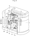
- the air cleaner 9 is disposed in the heat exchanger upstream room 20 as shown in Fig. 4 .
- the partition plate 21 forms a partition between the heat exchanger upstream room 20 and the cab 16.
- This partition plate 21 is located between a front part of the heat exchanger 15 and a rear surface of the cab 16 and is disposed upright on the revolving frame 5, extending in the left-right direction. Conduction of heat, noises and the like generated from the engine 7 to the inside of the cab 16 is prevented by this partition plate 21.
- the urea water tank 22 is located in the heat exchanger upstream room 20 and is provided on the revolving frame 5. This urea water tank 22 is adapted to store the urea water to be supplied to the urea water injection valve 14 provided in the connecting pipe 12 of the exhaust gas purifying device 10.
- the urea water tank 22 is accommodated in a tank receiver 23 and is disposed on the front side of the heat exchanger upstream room 20.
- An undercover 24 is provided on the lower side of the urea water tank 22.
- a water supply port 22B through which the urea water is supplied is provided on the upper end side of a left plate 22A of the urea water tank 22. Thereby, it is possible to supply the urea water with ease through the water supply port 22B in the urea water tank 22 by opening the left side cover 19B.
- a lid member 22D is provided on a top plate 22C of the urea water tank 22.
- the normal suction pipeline 27 and a heater-equipped return pipeline 29 that will be described later are connected to this lid member 22D.
- a liquid gage (not shown) that measures a liquid volume of the urea water in the urea water tank 22 and a heater (not shown) that defrosts the urea water in the urea water tank 22 and the like are attached to the lid member 22D.
- the urea water pump 25 is disposed more rightward than the urea water tank 22 in the heat exchanger upstream room 20. Specifically, the urea water pump 25 is disposed on the right of the urea water tank 22 and is attached to the partition plate 21 with three bolts 26.
- a suction port 25A, a return port 25B, a supply port 25C are provided in an upper surface of the urea water pump 25 from the left side separately each other in the left-right direction.
- the normal suction pipeline 27 that will be described later is connected to the suction port 25A and the heater-equipped return pipeline 29 that will be described later is connected to the return port 25B.
- the supply pipeline 28 that will be described later is connected to the supply port 25C.
- cables such as an electric wire, a signal line and the like are connected to the urea water pump 25.
- the urea water pump 25 is adapted to supply the urea water stored in the urea water tank 22 toward the urea water injection valve 14.
- a control valve (not shown) that is opened and closed by a controller 32 is provided in the return port 25B. This control valve is closed when reversely driving the urea water pump 25.
- the normal suction pipeline 27 is provided so as to connect the urea water tank 22 and the urea water pump 25 to each other.
- This normal suction pipeline 27 is formed as a resinous pipe body that is not equipped with a heating wire 29B that will be described later and is the one through which the urea water sucked from the urea water tank 22 toward the urea water pump 25 flows.
- the normal suction pipeline 27 extends in the left-right direction as a whole as shown in Fig. 5 .
- the left end side of the normal suction pipeline 27 is connected to the lid member 22D of the urea water tank 22 and extends toward a lower part (a bottom part) in the urea water tank 22.
- the right end side of the normal suction pipeline 27 is connected to the suction port 25A in the urea water pump 25.
- the supply pipeline 28 is provided so as to connect the urea water pump 25 and the urea water injection valve 14 to each other.
- the urea water to be supplied toward the urea water injection valve 14 by the urea water pump 25 flows through this supply pipeline 28.
- the supply pipeline 28 is composed of, for example, a resinous pipe body, the one end side is connected to the supply port 25C in the urea water pump 25 and the other end side is connected to the urea water injection valve 14 as shown in Fig. 3 , Fig. 5 .
- a not shown heating wire for the supply pipeline is wound on an outer periphery of the supply pipeline 28 and generates heat in accordance with a command from the controller 32 that will be described later. Thereby, freezing of the urea water that flows in the supply pipeline 28 is suppressed with heat of the heating wire for the supply pipeline.
- the engine cooling water that is warmed by the engine 7 in place of the heating wire for the supply pipeline may be used in the supply pipeline 28.
- the heater-equipped return pipeline 29 is provided so as to connect the urea water pump 25 and the urea water tank 22 to each other.
- This heater-equipped return pipeline 29 is composed of, for example, a resinous pipe body and is configured by a return pipeline 29A through which the urea water that is returned from the urea water pump 25 toward the urea water tank 22 flows and the heating wire 29B that is wound on the outer circumference of the return pipeline 29Aserving as a heater.
- the heater-equipped return pipeline 29 extends in the left-right direction as a whole as shown in Fig. 5 .
- the left end side of the heater-equipped return pipeline 29 is connected to the lid member 22D of the urea water tank 22 and projects into the urea water tank 22.
- the right end side of the heater-equipped return pipeline 29 is connected to the return port 25B in the urea water pump 25.
- the heating wire 29B is composed of, for example, a nickel-chrome wire, a ferrochrome wire and the like.
- the heating wire 29B is configured by a plus-side heating wire 29B1 that is helically wound on an outer circumference of the return pipeline 29A from the right end side (the return port 25B side of the urea water pump 25) toward the left end side (the lid member 22D side of the urea water tank 22) of the return pipeline 29A and a minus-side heating wire 29B2 that is helically wound on the outer circumference of the return pipeline 29A toward the right end side by being folded back on the left end side of the return pipeline 29A. That is, the heating wire 29B is, the plus-side heating wire 29B1 and the minus-side heating wire 29B2 are alternately wound (see Fig. 5 , Fig. 6 ).
- the plus-side heating wire 29B1 of the heating wire 29B is connected to a conductive wire 30A and this conductive wire 30A is connected to a power source via a control board in the controller 32.
- the minus-side heating wire 29B2 is connected with a conductive wire 30B and this conductive wire 30B is connected to a body earth via the control board in the controller 32.
- the heating wire 29B generates heat by supply of electric power from the power source in accordance with a command from the controller 32 that will be described later.
- the heat generated from the heating wire 29B is conducted to the urea water in the return pipeline 29A and thereby it is possible to defrost the frozen urea water. That is, the heater-equipped return pipeline 29 has a defrosting performance that makes defrosting of the frozen urea water possible.
- the heater-equipped return pipeline 29 id disposed along the normal suction pipeline 27 as shown in Fig. 5 , Fig. 6 . That is, the heater-equipped return pipeline 29 and the normal suction pipeline 27 are disposed in parallel in a state of contact with each other. Thereby, it is possible to suppress freezing of the urea water by conducting the heat generated from the heating wire 29B to the urea water in the normal suction pipeline 27. That is, the normal suction pipeline 27 has a warm-keeping performance that makes warm-keeping of the urea water that flows in the normal suction pipeline 27 possible.
- a heat-insulating cover 31 is provided between the urea water tank 22 and the urea water pump 25.
- This heat-insulating cover 31 is formed as a pipe body made of, for example, polyethylene, polypropylene and the like.
- the heat-insulating cover 31 is adapted to surround the heater-equipped return pipeline 29 and the normal suction pipeline 27 together.
- the heat-insulating cover 31 is adapted to efficiently keep the heat generated from the heating wire 29B warm by shutting off the heating wire 29B from the outdoor air. Since diffusion of the heat generated from the heating wire 29B is suppressed by the heat-insulating cover 31, it is possible to lower a temperature of the heating wire 29B and to shorten a winding length of the heating wire 29B in comparison with a case where the heat-insulating cover 31 is not used. Thereby, since it is possible to efficiently perform defrosting of the heater-equipped return pipeline 29 and warm-keeping of the normal suction pipeline 27, it is possible to reduce a cost.
- the controller 32 is located above the urea water tank 22 and the urea water pump 25 and is attached to the partition plate 21. This controller 32 is connected to the exhaust gas purifying device 10, the urea water injection valve 14, the urea water tank 22, the urea water pump 25 and the like via, for example, not shown signal lines.
- the controller 32 is adapted to perform on-off valve control of the urea water injection valve 14 and control of driving of the urea water pump 25 and the like in accordance with an operation condition (for example, a displacement volume of the exhaust gas and the like) of the hydraulic excavator 1.
- controller 32 controls heat generation of the heating wire for the supply pipeline and further controls heat generation of the heating wire 29B via the conductive wires 30A, 30B depending on, for example, an outdoor air temperature, a water temperature of the urea water and the like.
- the hydraulic excavator 1 has such a configuration as described above and next, operations of this hydraulic excavator 1 will be described.
- the operator gets on the cab 16 and sits on the driver's seat.
- the engine 7 is started to drive the hydraulic pump by operating the key switch in this state.
- the hydraulic pump is driven and pressurized oil that serves as the power source is secured.
- the operator is able to drive the lower traveling structure 2 so as to move the hydraulic excavator 1 forward or backward by operating an accelerator pedal and the steering wheel that are used for traveling.
- the operator who sits on the driver's seat is able to perform earth and sand excavation work and the like by operating the operation lever for work and thereby tiltably moving the front device 4.
- the exhaust gas emitted from the engine 7 is purified by the exhaust gas purifying device 10 and is emitted into the atmosphere.
- the exhaust gas emitted from the engine 7 is, carbon monoxide (CO), hydrocarbon (HC) and the like contained in the exhaust gas are removed by the first exhaust gas post-treatment device 11.
- the exhaust gas is hydrolyzed with the urea water injected from the urea water injection valve 14 in the connecting pipe 12 and thereby ammonia is generated.
- the exhaust gas is emitted into the atmosphere after the nitrogen oxide (NOx) is made to selectively undergo reduction reaction with the ammonia generated from the urea water solution and is decomposed into nitrogen and water by the second exhaust gas post-treatment device 13.
- NOx nitrogen oxide
- the controller 32 determines the state (freezing, a filling amount and the like) of the urea water in the urea water tank 22.
- the controller 32 makes driving of the urea water pump 25 start.
- the urea water in the urea water tank 22 circulates and flows through the normal suction pipeline 27, the urea water pump 25, the heater-equipped return pipeline 29. In this case, part of the urea water flows from the urea water pump 25 into the supply pipeline 28 and is supplied to the urea water injection valve 14.
- the controller 32 determines whether a pressure in the supply pipeline 28 reaches a predetermined value or not with the inside of the supply pipeline 28 being filled with the urea water. When the controller 32 determines that the pressure in the supply pipeline 28 reaches the predetermined value, the controller 32 performs control of the on-off value of the urea water injection valve 14 in accordance with the exhaust volume of the exhaust gas and the like. Thereby, the urea water is injected into the exhaust gas that flows in the connecting pipe 12 of the exhaust gas purifying device 10.
- the controller 32 stops driving of the urea water pump 25. Subsequently, the controller 32 closes the control valve of the return port 25B in the urea water pump 25 and starts reverse driving of the urea water pump 25.
- the controller 32 stops the reverse driving of the urea water pump 25.
- the heating wire 29B is wound on the outer periphery of the return pipeline 29A to form the return pipeline 29A as the heater-equipped return pipeline 29 in the present embodiment.
- the suction pipeline is formed as the normal suction pipeline 27 that is not equipped with the heating wire (the heater).
- the heater-equipped return pipeline 29 and the normal suction pipeline 27 are disposed in parallel in the state of contact with each other.
- the heater-equipped return pipeline 29 has the sufficient defrosting performance owing to the heating wire 29B.
- the normal suction pipeline 27 is disposed in the state of contact with the heating wire 29B that is wound on the outer circumference of the return pipeline 29A and therefore it is possible to have the sufficient warm-keeping performance. Accordingly, for example, when the vehicle body is stopped in a work site where the outdoor air temperature reaches -11 °C or below, it is possible to defrost the frozen urea water with the heat generated from the heating wire 29B that is wound on the outer circumference of the return pipeline 29A irrespective of freezing of the urea water that remains in the return pipeline 29A.
- the heating wire 29B when the outdoor air temperature approaches -11 °C in operation of the vehicle body, the heating wire 29B generates heat and thereby it is possible to keep the return pipeline 29A warm. Further, since the normal suction pipeline 27 is disposed in parallel with the heater-equipped return pipeline 29 in the state of contact with each other, warm-keeping thereof is possible. Thereby, it is possible to suppress freezing of the urea water that flows in the return pipeline 29A and the normal suction pipeline 27.
- the normal suction pipeline 27 is warmed by the heating wire 29B of the heater-equipped return pipeline 29, it is possible to suppress freezing of the urea water that flows in the normal suction pipeline 27. Accordingly, it is possible for the normal suction pipeline 27 to efficiently secure the warm-keeping performance by using the heating wire 29B of the heater-equipped return pipeline 29 without using a dedicated heating wire (the heater). Consequently, it is possible to reduce the power consumption and therefore it is possible to reduce the cost.
- the heater-equipped return pipeline 29 and the normal suction pipeline 27 are surrounded together by the heat-insulating cover 31.
- the heat-insulating cover 31 since a warm-keeping state of the heat generated from the heating wire 29B is improved in the heat-insulating cover 31, it is possible to lower the temperature of the heating wire 29B and to shorten the length of the heating wire 29B in comparison with a case of not using the heat-insulating cover 31 and it is possible to more reduce the cost.
- the aforementioned first embodiment is explained by taking a case where the urea water tank 22 and the urea water pump 25 are disposed in the heat exchanger upstream room 20 as an example.
- the present invention is not limited thereto but the urea water pump 25 and the urea water tank 22 may be provided, for example, on the revolving frame 5 other than the heat exchanger upstream room 20.
- the urea water tank 22 and the urea water pump 25 are attached to the partition plate 21 as an example.
- the present invention is not limited thereto, but the urea water tank 22 and the urea water pump 25 may be disposed, for example, on the counterweight 6 side.
- the present invention is not limited thereto, but it is widely applicable also to other construction machines such as, for example, a crawler mounted hydraulic excavator, a hydraulic crane and the like. Further, it is applicable also to an electric powered construction machine that drives the hydraulic pump by an electric motor and a hybrid-type construction machine with the engine and the electric motor being mounted.
Landscapes
- Engineering & Computer Science (AREA)
- Chemical & Material Sciences (AREA)
- Chemical Kinetics & Catalysis (AREA)
- General Engineering & Computer Science (AREA)
- Health & Medical Sciences (AREA)
- Combustion & Propulsion (AREA)
- Toxicology (AREA)
- Mechanical Engineering (AREA)
- Mining & Mineral Resources (AREA)
- Structural Engineering (AREA)
- Civil Engineering (AREA)
- Biomedical Technology (AREA)
- Oil, Petroleum & Natural Gas (AREA)
- General Chemical & Material Sciences (AREA)
- Analytical Chemistry (AREA)
- Environmental & Geological Engineering (AREA)
- Exhaust Gas After Treatment (AREA)
- Component Parts Of Construction Machinery (AREA)
- Exhaust Gas Treatment By Means Of Catalyst (AREA)
Abstract
Description
- The present invention relates to a construction machine such as a hydraulic excavator and the like with a urea water tank that stores urea water and a urea water pump that supplies the urea water in the urea water tank to an exhaust gas purifying device being mounted.
- In general, the hydraulic excavator as a representative example of the construction machine comprising: an automotive vehicle body; an engine that is mounted on the vehicle body; an exhaust gas purifying device that is connected to an exhaust pipe of the engine and is provided with a urea selective reduction catalyst that removes a nitrogen oxide in an exhaust gas; a urea water injection valve that is provided in the exhaust gas purifying device and injects urea water that is a reducing agent to the upstream side of the urea selective reduction catalyst; a urea water tank that stores the urea water to be supplied to the urea water injection valve; a urea water pump that supplies the urea water that is stored in the urea water tank toward the urea water injection valve.
- In this case, the urea water tank and the urea water pump are connected to each other via a suction pipeline through which the urea water that is sucked from the urea water tank toward the urea water pump flows and a return pipeline through which the urea water that is returned from the urea water pump toward the urea water tank flows. The urea water pump and the urea water injection valve are connected to each other via a supply pipeline through which the urea water that is supplied toward the urea water injection valve by the urea water pump flows.
- A warming pipeline through which engine cooling water warmed by an engine flows is provided in the urea water tank and suppresses (defrosts) freezing of the urea water stored in the urea water tank (Patent Document 1). In addition, the one that uses the engine cooling water warmed by the engine and the one that uses a heater such as a heating wire and the like are known as the ones that suppress freezing of the urea water in the suction pipeline, the return pipeline, the supply pipeline.
- Patent Document 1: Japanese Patent Application Laid-Open No.
2012-225304 A - Incidentally, in a case where the engine cooling water is used for defrosting the urea water, it is necessary to drive the engine. In addition, since a sufficient time is necessary to warm the engine cooling water after driving of the engine, there is a possibility that the time may be taken to defrost the urea water. On the other hand, the heater such as the heating wire and the like is excellent in defrosting performance in comparison with a case of using the engine cooling water. However, since power consumption is increased, a large-capacity generator becomes necessary. Further, since the heating wire, a connector and the like become newly necessary, there is a possibility that a cost may be increased.
- In view of the above-described problems with the conventional art, it is an object of the present invention to provide a construction device that is able to reduce the cost by efficiently suppressing freezing of the urea water.
- The present invention is characterized in that a construction machine comprising: an automotive vehicle body; an engine that is mounted on the vehicle body; an exhaust gas purifying device that is connected to an exhaust pipe of the engine and includes a urea selective reduction catalyst that removes a nitrogen oxide in an exhaust gas; a urea water injection valve that is provided in the exhaust gas purifying device and injects urea water that is a reducing agent to the upstream side of the urea selective reduction catalyst; a urea water tank that stores the urea water to be supplied to the urea water injection valve; a urea water pump that supplies the urea water that is stored in the urea water tank toward the urea water injection valve; a suction pipeline that is provided so as to connect the urea water tank and the urea water pump to each other and through which the urea water that is sucked from the urea water tank toward the urea water pump flows; a return pipeline that is provided so as to connect the urea water pump and the urea water tank to each other and through which the urea water that is returned from the urea water pump toward the urea water tank flows; and a supply pipeline that is provided so as to connect the urea water pump and the urea water injection valve to each other and through which the urea water that is supplied toward the urea water injection valve by the urea water pump flows, characterized in that: the return pipeline is formed as a heater-equipped return pipeline that is equipped with a heater adapted to heat the urea water therein, the suction pipeline is formed as a normal suction pipeline that is not equipped with the heater, and the heater-equipped return pipeline and the normal suction pipeline are disposed in parallel in a state of contact with each other.
- According to the present invention, it is possible to reduce the cost by efficiently suppressing freezing of the urea water.
-
-
Fig. 1 is a front view showing a hydraulic excavator according to an embodiment of the present invention.-
Fig. 2 is an enlarged plan view showing the hydraulic excavator that a part of a front device is omitted. -
Fig. 3 is a plan view showing a revolving frame, an engine, a heat exchanger, an exhaust gas treatment device, a urea water tank, a urea water pump, a heat-insulating cover, a supply pipeline and the like in a state where an air cleaner is omitted. -
Fig. 4 is a perspective view showing a cab, a counter weight, a partition plate, the urea water tank, the urea water pump, the heat-insulating cover, the supply pipeline and the like viewed from left rear in a state where a left side cover is removed. -
Fig. 5 is a sectional view showing the partition plate, the urea water tank, the urea water tank, a normal suction pipeline, a heater-equipped return pipeline, the supply pipeline, the heat-insulating cover and the like viewed in the direction of an arrow V-V inFig. 4 . -
Fig. 6 is a sectional view showing the normal suction pipeline, the heater-equipped return pipeline, the heat-insulating cover inFig. 5 viewed in the direction of an arrow VI-VI.
-
- Hereinafter, a construction machine according to an embodiment of the present invention will be described in detail with reference to
Fig. 1 to Fig. 6 by taking a wheel-type hydraulic excavator as a representative example. - In
Fig. 1 , ahydraulic excavator 1 is configured by an automotive wheel-typelower traveling structure 2 having left and rightfront wheels 2A and left and rightrear wheels 2B, an upper revolvingstructure 3 that is rotatably mounted on thelower traveling structure 2, and afront device 4 that is tiltably provided on the upper revolvingstructure 3. Here, the wheel-typehydraulic excavator 1 includes thelower traveling structure 2 and the upper revolvingstructure 3 and thereby a vehicle body of the present invention is configured. - The
front device 4 is configured by aboom 4A, anarm 4B, abucket 4C, aboom cylinder 4D, anarm cylinder 4E, abucket cylinder 4F and the like. Afoot part 4G of theboom 4A is rotatably attached to an intermediate part in a left-right direction on the front side of a revolvingframe 5 that will be described later as shown inFig. 2 . - The revolving
frame 5 is the one that configures a support structure body of the upper revolvingstructure 3 and is rotatably mounted on thelower traveling structure 2 with thefoot part 4G of thefront device 4 being attached to the front side thereof. The revolvingframe 5 is configured by including abottom plate 5A that is composed of a thick steel plate and the like that extends in a front-rear direction, a leftvertical plate 5B and a rightvertical plate 5C that are installed upright on thebottom plate 5A and extending in the front-rear direction with a predetermined interval in the left-right direction, aleft side frame 5D and aright side frame 5E that are disposed on the left and the right of the respectivevertical plates extension beams 5F that extend from thebottom plate 5A, each of thevertical plates right side frames Fig. 3 . The front device 4 (thefoot part 4G) is tiltably mounted to the front sides of each of thevertical plates counterweight 6 that will be described later is attached to the rear sides thereof. - The
counterweight 6 is provided on rear ends of the left and rightvertical plates frame 5. Thiscounterweight 6 acts as a weight balance to thefront device 4. A rear surface of thecounterweight 6 is formed into a substantially arc shape centering on a revolving center of the upper revolving structure 3 (seeFig. 2 ). - An
engine 7 is located on the front side of thecounterweight 6 and is provided on the rear part of the revolvingframe 5. Thisengine 7 is mounted on horizontally placed state where it extends in the left-right direction as shown inFig. 3 . Acooling fan 8 that sucks outdoor air as cooling air is disposed on the left side that is the one side in the left-right direction of theengine 7. On the other hand, a hydraulic pump (not shown) is disposed on the right side that is the other side in the left-right direction of theengine 7, located on the lower side of an exhaust gas purifyingdevice 10 that will be described later. The hydraulic pump is adapted to supply pressurized oil toward various kinds of hydraulic actuators provided in the upper revolvingstructure 3, thefront device 4 by being driven by theengine 7. - In addition, a not shown intake pipe is connected to the intake side of the
engine 7 and anair cleaner 9 is attached to the distal end side of this intake pipe. Thisair cleaner 9 is disposed in a heat exchangerupstream room 20 that will be described later, centrifuges dust in sucked air and makes only purified air flow to theengine 7. On the other hand, anexhaust pipe 7A is connected to the exhaust side of theengine 7. - The exhaust gas purifying
device 10 is connected to theexhaust pipe 7A of theengine 7. This exhaust gas purifyingdevice 10 is located on the right side of theengine 7 and is disposed above the hydraulic pump. The exhaust gas purifyingdevice 10 is adapted to remove hazardous substances in an exhaust gas emitted from theengine 7. In addition, the exhaust gas purifyingdevice 10 is equipped with a silencing mechanism adapted to reduce noises of the exhaust gas. The exhaust gas purifyingdevice 10 is configured by including a first exhaustgas post-treatment device 11, a connectingpipe 12, a second exhaustgas post-treatment device 13. - The first exhaust
gas post-treatment device 11 is connected to the exit side of theexhaust pipe 7A. This first exhaust gaspost-treatment device 11 is composed of a cylindrical body that extends in the front-rear direction and is disposed above the hydraulic pump and below the second exhaustgas post-treatment device 13 that will be described later. An oxidation catalyst (not shown) that is composed of, for example, a cell-type tubular body which is made from ceramics is provided in the first exhaustgas post-treatment device 11. - Many numbers of through-holes are formed in an axial direction in this oxidation catalyst and an inner surface is coated with a noble metal. The oxidation catalyst is adapted to oxidize and remove carbon monoxide (CO), hydrocarbon (HC) and the like contained in the exhaust gas by making the exhaust gas flow through the through-holes under a predetermined temperature. In addition, it is adapted to burn and remove particulate matters (PM) as necessary.
- The connecting
pipe 12 is disposed above the first exhaustgas post-treatment device 11, extending in the front-rear direction. The connectingpipe 12 is adapted to make a connection between the first exhaustgas post-treatment device 11 and the second exhaustgas post-treatment device 13. Specifically, the connectingpipe 12 is connected to the front end side (the downstream side of a flowing direction of the exhaust gas) of the first exhaust gaspost-treatment device 11 and to the rear end side (the upstream side of the flowing direction of the exhaust gas) of the second exhaust gaspost-treatment device 13. In addition, a urea water injection valve 14 that will be described later is provided on the front end side (the upstream side of the flowing direction of the exhaust gas) of the connectingpipe 12. - The second exhaust gas
post-treatment device 13 is disposed on the left upper side of the first exhaust gaspost-treatment device 11. This second exhaust gaspost-treatment device 13 is connected to the exit side of the connectingpipe 12 and is formed as a cylindrical body that extends in the front-rear direction in parallel with the first exhaust gaspost-treatment device 11. A ureaselective reduction catalyst 13A and anoxidation catalyst 13B are disposed in the second exhaust gas post-treatment device 13 (seeFig. 3 ). - The urea
selective reduction catalyst 13A is composed of, for example, a cell-type tubular body which is made from ceramics, many numbers of through-holes are formed therein in an axial direction thereof and an inner surface is coated with the noble metal. The ureaselective reduction catalyst 13A makes a nitrogen oxide (NOx) that is in general contained in the exhaust gas emitted from theengine 7 selectively undergo a reduction reaction with ammonia generated from a urea water solution and decomposes it into nitrogen and water. - The
oxidation catalyst 13B is provided on the more downstream side of the flowing direction of the exhaust gas than the ureaselective reduction catalyst 13A. Thisoxidation catalyst 13B is composed of a cell-type tubular body which is made from ceramics, many numbers of through-holes are formed therein in an axial direction thereof and an inner surface is coated with the noble metal substantially similarly to the oxidation catalyst of the aforementioned first exhaust gaspost-treatment device 11. Thereby, theoxidation catalyst 13B oxidizes remaining ammonia that remains after reducing the nitrogen oxide by the ureaselective reduction catalyst 13A and decomposes it into nitrogen and water. - The urea water injection valve 14 is provided on the front end side of the connecting
pipe 12. This urea water injection valve 14 is connected to aurea water tank 22 that will be described later and stores the urea water solution via aurea water pump 25, anormal suction pipeline 27, asupply pipeline 28. The urea water injection valve 14 is adapted to inject the urea water that is a reducing agent to the more upstream side than the ureaselective reduction catalyst 13A toward the exhaust gas that flows in the connectingpipe 12. - A
heat exchanger 15 is disposed facing the coolingfan 8 so as to locate on the upstream side of a flowing direction of cooling air by the coolingfan 8. Thisheat exchanger 15 is configured by, for example, a radiator that cools the engine cooling water, an oil cooler that cools a hydraulic oil, an intercooler that cools air that theengine 7 sucks and the like. Theheat exchanger 15 is covered with ahousing 19 that will be described later together with theengine 7, the hydraulic pump and the like. - A
cab 16 is located on the left side with thefoot part 4G of thefront device 4 being interposed and is provided on the revolvingframe 5. Thiscab 15 is the one on which an operator will get on and a driver's seat on which the operator will sit, a steering wheel used for traveling, an operation lever used for work and the like (any of them is not shown) are disposed therein. Further, key switches (not shown) used for operating on/off switching of an electrical system of thehydraulic excavator 1, start and stop of theengine 7 and the like are disposed in the vicinity of the driver's seat. - A
hydraulic oil tank 17 is located on the front side of the engine and on the right side with thefoot part 4G of thefront device 4 being interposed and is provided on the revolvingframe 5. Thishydraulic oil tank 17 is adapted to store hydraulic oil to be supplied to various kinds of actuators mounted on thehydraulic excavator 1. On the other hand, afuel tank 18 is provided on the revolvingframe 5 adjacent to the right side of thehydraulic oil tank 17. Thisfuel tank 18 is adapted to store fuel to be supplied to theengine 7. - The
housing 19 is located on the rear side of the upper revolvingstructure 3 and is provided on the revolvingframe 5. Thishousing 19 is located around thecounterweight 6, thecab 16, thehydraulic oil tank 17 and thefuel tank 18 and is adapted to cover mounted devices including theengine 7, theheat exchanger 15 and the like. Thehousing 19 is configured by atop surface cover 19A that covers over theengine 7, theheat exchanger 15 and the like, aleft side cover 19B that falls from a left end of thetop surface cover 19A so as to face theheat exchanger 15, and aright side cover 19C that falls from a right end of thetop surface cover 19A. - The
left side cover 19B is disposed on one side surface in the left-right direction of the revolvingframe 5, that is, on theleft side frame 5D so as to be openable/closable with, for example, a front part being set as a fulcrum. That is, theleft side cover 19B is attached to apartition plate 21 that will be described later via a hinge (not shown) and thereby closes the left side of the heat exchangerupstream room 20 that will be described later to be openable/closable. - The heat exchanger
upstream room 20 is the one that is provided between thecab 16 and thecounterweight 6. That is, the heat exchangerupstream room 20 is provided on the more upstream side than theheat exchanger 15 relative to the flowing direction of the cooling air to be supplied to theheat exchanger 15. This heat exchangerupstream room 20 is a space surrounded by thehousing 19, thepartition plate 21 that will be described later and thecounterweight 6. - Specifically, the heat exchanger
upstream room 20 is closed with thetop surface cover 19A of thehousing 19 on its top, is closed with thepartition plate 21 on its front and is closed with thecounterweight 6 on its rear. In addition, the left of the heat exchangerupstream room 20 is closed with theleft side cover 19B to be openable/closable. On the other hand, theheat exchanger 15 is disposed on the right of the heat exchangerupstream room 20. Further, theair cleaner 9 is disposed in the heat exchangerupstream room 20 as shown inFig. 4 . - The
partition plate 21 forms a partition between the heat exchangerupstream room 20 and thecab 16. Thispartition plate 21 is located between a front part of theheat exchanger 15 and a rear surface of thecab 16 and is disposed upright on the revolvingframe 5, extending in the left-right direction. Conduction of heat, noises and the like generated from theengine 7 to the inside of thecab 16 is prevented by thispartition plate 21. - The
urea water tank 22 is located in the heat exchangerupstream room 20 and is provided on the revolvingframe 5. Thisurea water tank 22 is adapted to store the urea water to be supplied to the urea water injection valve 14 provided in the connectingpipe 12 of the exhaustgas purifying device 10. Theurea water tank 22 is accommodated in atank receiver 23 and is disposed on the front side of the heat exchangerupstream room 20. An undercover 24 is provided on the lower side of theurea water tank 22. - A
water supply port 22B through which the urea water is supplied is provided on the upper end side of aleft plate 22A of theurea water tank 22. Thereby, it is possible to supply the urea water with ease through thewater supply port 22B in theurea water tank 22 by opening theleft side cover 19B. - In addition, a
lid member 22D is provided on atop plate 22C of theurea water tank 22. Thenormal suction pipeline 27 and a heater-equippedreturn pipeline 29 that will be described later are connected to thislid member 22D. In addition, for example, a liquid gage (not shown) that measures a liquid volume of the urea water in theurea water tank 22 and a heater (not shown) that defrosts the urea water in theurea water tank 22 and the like are attached to thelid member 22D. - The
urea water pump 25 is disposed more rightward than theurea water tank 22 in the heat exchangerupstream room 20. Specifically, theurea water pump 25 is disposed on the right of theurea water tank 22 and is attached to thepartition plate 21 with threebolts 26. - A
suction port 25A, areturn port 25B, asupply port 25C are provided in an upper surface of theurea water pump 25 from the left side separately each other in the left-right direction. Thenormal suction pipeline 27 that will be described later is connected to thesuction port 25A and the heater-equippedreturn pipeline 29 that will be described later is connected to thereturn port 25B. In addition, thesupply pipeline 28 that will be described later is connected to thesupply port 25C. In addition, cables (not shown) such as an electric wire, a signal line and the like are connected to theurea water pump 25. Theurea water pump 25 is adapted to supply the urea water stored in theurea water tank 22 toward the urea water injection valve 14. A control valve (not shown) that is opened and closed by acontroller 32 is provided in thereturn port 25B. This control valve is closed when reversely driving theurea water pump 25. - The
normal suction pipeline 27 is provided so as to connect theurea water tank 22 and theurea water pump 25 to each other. Thisnormal suction pipeline 27 is formed as a resinous pipe body that is not equipped with aheating wire 29B that will be described later and is the one through which the urea water sucked from theurea water tank 22 toward theurea water pump 25 flows. Thenormal suction pipeline 27 extends in the left-right direction as a whole as shown inFig. 5 . The left end side of thenormal suction pipeline 27 is connected to thelid member 22D of theurea water tank 22 and extends toward a lower part (a bottom part) in theurea water tank 22. On the other hand, the right end side of thenormal suction pipeline 27 is connected to thesuction port 25A in theurea water pump 25. - The
supply pipeline 28 is provided so as to connect theurea water pump 25 and the urea water injection valve 14 to each other. The urea water to be supplied toward the urea water injection valve 14 by theurea water pump 25 flows through thissupply pipeline 28. Thesupply pipeline 28 is composed of, for example, a resinous pipe body, the one end side is connected to thesupply port 25C in theurea water pump 25 and the other end side is connected to the urea water injection valve 14 as shown inFig. 3 ,Fig. 5 . - For example, a not shown heating wire for the supply pipeline is wound on an outer periphery of the
supply pipeline 28 and generates heat in accordance with a command from thecontroller 32 that will be described later. Thereby, freezing of the urea water that flows in thesupply pipeline 28 is suppressed with heat of the heating wire for the supply pipeline. It should be noted that, the engine cooling water that is warmed by theengine 7 in place of the heating wire for the supply pipeline may be used in thesupply pipeline 28. - The heater-equipped
return pipeline 29 is provided so as to connect theurea water pump 25 and theurea water tank 22 to each other. This heater-equippedreturn pipeline 29 is composed of, for example, a resinous pipe body and is configured by areturn pipeline 29A through which the urea water that is returned from theurea water pump 25 toward theurea water tank 22 flows and theheating wire 29B that is wound on the outer circumference of the return pipeline 29Aserving as a heater. - The heater-equipped
return pipeline 29 extends in the left-right direction as a whole as shown inFig. 5 . The left end side of the heater-equippedreturn pipeline 29 is connected to thelid member 22D of theurea water tank 22 and projects into theurea water tank 22. On the other hand, the right end side of the heater-equippedreturn pipeline 29 is connected to thereturn port 25B in theurea water pump 25. - The
heating wire 29B is composed of, for example, a nickel-chrome wire, a ferrochrome wire and the like. Theheating wire 29B is configured by a plus-side heating wire 29B1 that is helically wound on an outer circumference of thereturn pipeline 29A from the right end side (thereturn port 25B side of the urea water pump 25) toward the left end side (thelid member 22D side of the urea water tank 22) of thereturn pipeline 29A and a minus-side heating wire 29B2 that is helically wound on the outer circumference of thereturn pipeline 29A toward the right end side by being folded back on the left end side of thereturn pipeline 29A. That is, theheating wire 29B is, the plus-side heating wire 29B1 and the minus-side heating wire 29B2 are alternately wound (seeFig. 5 ,Fig. 6 ). - The plus-side heating wire 29B1 of the
heating wire 29B is connected to aconductive wire 30A and thisconductive wire 30A is connected to a power source via a control board in thecontroller 32. On the other hand, the minus-side heating wire 29B2 is connected with aconductive wire 30B and thisconductive wire 30B is connected to a body earth via the control board in thecontroller 32. Theheating wire 29B generates heat by supply of electric power from the power source in accordance with a command from thecontroller 32 that will be described later. The heat generated from theheating wire 29B is conducted to the urea water in thereturn pipeline 29A and thereby it is possible to defrost the frozen urea water. That is, the heater-equippedreturn pipeline 29 has a defrosting performance that makes defrosting of the frozen urea water possible. - The heater-equipped
return pipeline 29 id disposed along thenormal suction pipeline 27 as shown inFig. 5 ,Fig. 6 . That is, the heater-equippedreturn pipeline 29 and thenormal suction pipeline 27 are disposed in parallel in a state of contact with each other. Thereby, it is possible to suppress freezing of the urea water by conducting the heat generated from theheating wire 29B to the urea water in thenormal suction pipeline 27. That is, thenormal suction pipeline 27 has a warm-keeping performance that makes warm-keeping of the urea water that flows in thenormal suction pipeline 27 possible. - A heat-insulating
cover 31 is provided between theurea water tank 22 and theurea water pump 25. This heat-insulatingcover 31 is formed as a pipe body made of, for example, polyethylene, polypropylene and the like. The heat-insulatingcover 31 is adapted to surround the heater-equippedreturn pipeline 29 and thenormal suction pipeline 27 together. - The heat-insulating
cover 31 is adapted to efficiently keep the heat generated from theheating wire 29B warm by shutting off theheating wire 29B from the outdoor air. Since diffusion of the heat generated from theheating wire 29B is suppressed by the heat-insulatingcover 31, it is possible to lower a temperature of theheating wire 29B and to shorten a winding length of theheating wire 29B in comparison with a case where the heat-insulatingcover 31 is not used. Thereby, since it is possible to efficiently perform defrosting of the heater-equippedreturn pipeline 29 and warm-keeping of thenormal suction pipeline 27, it is possible to reduce a cost. - The
controller 32 is located above theurea water tank 22 and theurea water pump 25 and is attached to thepartition plate 21. Thiscontroller 32 is connected to the exhaustgas purifying device 10, the urea water injection valve 14, theurea water tank 22, theurea water pump 25 and the like via, for example, not shown signal lines. Thecontroller 32 is adapted to perform on-off valve control of the urea water injection valve 14 and control of driving of theurea water pump 25 and the like in accordance with an operation condition (for example, a displacement volume of the exhaust gas and the like) of thehydraulic excavator 1. In addition, thecontroller 32 controls heat generation of the heating wire for the supply pipeline and further controls heat generation of theheating wire 29B via theconductive wires - The
hydraulic excavator 1 according to the present embodiment has such a configuration as described above and next, operations of thishydraulic excavator 1 will be described. - The operator gets on the
cab 16 and sits on the driver's seat. Theengine 7 is started to drive the hydraulic pump by operating the key switch in this state. The hydraulic pump is driven and pressurized oil that serves as the power source is secured. Then, the operator is able to drive thelower traveling structure 2 so as to move thehydraulic excavator 1 forward or backward by operating an accelerator pedal and the steering wheel that are used for traveling. On the other hand, the operator who sits on the driver's seat is able to perform earth and sand excavation work and the like by operating the operation lever for work and thereby tiltably moving thefront device 4. - In this case, the exhaust gas emitted from the
engine 7 is purified by the exhaustgas purifying device 10 and is emitted into the atmosphere. Specifically, the exhaust gas emitted from theengine 7 is, carbon monoxide (CO), hydrocarbon (HC) and the like contained in the exhaust gas are removed by the first exhaust gaspost-treatment device 11. Subsequently, the exhaust gas is hydrolyzed with the urea water injected from the urea water injection valve 14 in the connectingpipe 12 and thereby ammonia is generated. Thereafter, the exhaust gas is emitted into the atmosphere after the nitrogen oxide (NOx) is made to selectively undergo reduction reaction with the ammonia generated from the urea water solution and is decomposed into nitrogen and water by the second exhaust gaspost-treatment device 13. - Next, driving control of the
urea water pump 25 that thecontroller 32 performs will be described. - First, when the operator starts the
engine 7 by turning the key switch on, thecontroller 32 determines the state (freezing, a filling amount and the like) of the urea water in theurea water tank 22. When thecontroller 32 determines that there is no trouble in the state of the urea water, thecontroller 32 makes driving of theurea water pump 25 start. - When driving of the
urea water pump 25 is started, the urea water in theurea water tank 22 circulates and flows through thenormal suction pipeline 27, theurea water pump 25, the heater-equippedreturn pipeline 29. In this case, part of the urea water flows from theurea water pump 25 into thesupply pipeline 28 and is supplied to the urea water injection valve 14. - The
controller 32 determines whether a pressure in thesupply pipeline 28 reaches a predetermined value or not with the inside of thesupply pipeline 28 being filled with the urea water. When thecontroller 32 determines that the pressure in thesupply pipeline 28 reaches the predetermined value, thecontroller 32 performs control of the on-off value of the urea water injection valve 14 in accordance with the exhaust volume of the exhaust gas and the like. Thereby, the urea water is injected into the exhaust gas that flows in the connectingpipe 12 of the exhaustgas purifying device 10. - On the other hand, when the operator stops driving of the
engine 7 by turning the switch key off, thecontroller 32 stops driving of theurea water pump 25. Subsequently, thecontroller 32 closes the control valve of thereturn port 25B in theurea water pump 25 and starts reverse driving of theurea water pump 25. - Thereby, the urea water that remains in the
normal suction pipeline 27 and in thesupply pipeline 28 is returned to theurea water tank 22. Accordingly, it is possible to suppress remaining of the urea water in thenormal suction pipeline 27 and in thesupply pipeline 28 when the vehicle body is stopped. Thereafter, thecontroller 32 stops the reverse driving of theurea water pump 25. - Incidentally, there is a possibility that it may be impossible to return the urea water in the return pipeline to the urea water tank when the vehicle body is stopped in the above-described prior art. In this case, for example, when the temperature reaches a urea water freezing point or below (for example, -11 °C), the urea water freezes. In particular, since the urea water in the return pipeline is small in residual amount in comparison with a storage amount of the urea water in the urea water tank, there is a possibility that the urea water may freeze in a short period of time.
- When the urea water pump is driven in a state where the urea water that remains in the return pipeline freezes, it is not possible to make the urea water smoothly circulate (flow) and there is a possibility that it may become impossible to appropriately perform control of exhaust gas purification treatment.
- Whereas, the
heating wire 29B is wound on the outer periphery of thereturn pipeline 29A to form thereturn pipeline 29A as the heater-equippedreturn pipeline 29 in the present embodiment. On the other hand, the suction pipeline is formed as thenormal suction pipeline 27 that is not equipped with the heating wire (the heater). The heater-equippedreturn pipeline 29 and thenormal suction pipeline 27 are disposed in parallel in the state of contact with each other. - Thereby, the heater-equipped
return pipeline 29 has the sufficient defrosting performance owing to theheating wire 29B. On the other hand, thenormal suction pipeline 27 is disposed in the state of contact with theheating wire 29B that is wound on the outer circumference of thereturn pipeline 29A and therefore it is possible to have the sufficient warm-keeping performance. Accordingly, for example, when the vehicle body is stopped in a work site where the outdoor air temperature reaches -11 °C or below, it is possible to defrost the frozen urea water with the heat generated from theheating wire 29B that is wound on the outer circumference of thereturn pipeline 29A irrespective of freezing of the urea water that remains in thereturn pipeline 29A. - On the other hand, when the outdoor air temperature approaches -11 °C in operation of the vehicle body, the
heating wire 29B generates heat and thereby it is possible to keep thereturn pipeline 29A warm. Further, since thenormal suction pipeline 27 is disposed in parallel with the heater-equippedreturn pipeline 29 in the state of contact with each other, warm-keeping thereof is possible. Thereby, it is possible to suppress freezing of the urea water that flows in thereturn pipeline 29A and thenormal suction pipeline 27. - That is, since the
normal suction pipeline 27 is warmed by theheating wire 29B of the heater-equippedreturn pipeline 29, it is possible to suppress freezing of the urea water that flows in thenormal suction pipeline 27. Accordingly, it is possible for thenormal suction pipeline 27 to efficiently secure the warm-keeping performance by using theheating wire 29B of the heater-equippedreturn pipeline 29 without using a dedicated heating wire (the heater). Consequently, it is possible to reduce the power consumption and therefore it is possible to reduce the cost. - Further, the heater-equipped
return pipeline 29 and thenormal suction pipeline 27 are surrounded together by the heat-insulatingcover 31. Thereby, since a warm-keeping state of the heat generated from theheating wire 29B is improved in the heat-insulatingcover 31, it is possible to lower the temperature of theheating wire 29B and to shorten the length of theheating wire 29B in comparison with a case of not using the heat-insulatingcover 31 and it is possible to more reduce the cost. - It should be noted that the aforementioned first embodiment is explained by taking a case where the
urea water tank 22 and theurea water pump 25 are disposed in the heat exchangerupstream room 20 as an example. However, the present invention is not limited thereto but theurea water pump 25 and theurea water tank 22 may be provided, for example, on the revolvingframe 5 other than the heat exchangerupstream room 20. - In addition, in the above-described embodiment is explained by taking a case where the
urea water tank 22 and theurea water pump 25 are attached to thepartition plate 21 as an example. However, the present invention is not limited thereto, but theurea water tank 22 and theurea water pump 25 may be disposed, for example, on thecounterweight 6 side. - In addition, in the above-described embodiment is explained by taking the small revolving type wheel-system
hydraulic excavator 1 as an example as the construction machine. However, the present invention is not limited thereto, but it is widely applicable also to other construction machines such as, for example, a crawler mounted hydraulic excavator, a hydraulic crane and the like. Further, it is applicable also to an electric powered construction machine that drives the hydraulic pump by an electric motor and a hybrid-type construction machine with the engine and the electric motor being mounted. -
- 1:
- Hydraulic excavator (Construction machine)
- 2:
- Lower traveling structure (Vehicle body)
- 3:
- Upper revolving structure (Vehicle body)
- 7:
- Engine
- 7A:
- Exhaust pipe
- 10:
- Exhaust gas purifying device
- 13A:
- Urea selective reduction catalyst
- 14:
- Urea water injection valve
- 22:
- Urea water tank
- 25:
- Urea water pump
- 27:
- Normal suction pipeline (Suction pipeline)
- 28:
- Supply pipeline
- 29:
- Heater-equipped return pipeline
- 29A:
- Return pipeline
- 29B:
- Heating wire (Heater)
- 31:
- Heat-insulating cover
Claims (3)
- A construction machine comprising:an automotive vehicle body;an engine that is mounted on said vehicle body;an exhaust gas purifying device that is connected to an exhaust pipe of said engine and includes a urea selective reduction catalyst that removes a nitrogen oxide in an exhaust gas;a urea water injection valve that is provided in said exhaust gas purifying device and injects urea water that is a reducing agent to the upstream side of said urea selective reduction catalyst;a urea water tank that stores the urea water to be supplied to said urea water injection valve;a urea water pump that supplies the urea water that is stored in said urea water tank toward said urea water injection valve;a suction pipeline that is provided so as to connect said urea water tank and said urea water pump to each other and through which the urea water that is sucked from said urea water tank toward said urea water pump flows;a return pipeline that is provided so as to connect said urea water pump and said urea water tank to each other and through which the urea water that is returned from said urea water pump toward said urea water tank flows; anda supply pipeline that is provided so as to connect said urea water pump and said urea water injection valve to each other and through which the urea water that is supplied toward said urea water injection valve by said urea water pump flows, characterized in that:said return pipeline is formed as a heater-equipped return pipeline that is equipped with a heater adapted to heat the urea water therein,said suction pipeline is formed as a normal suction pipeline that is not equipped with said heater, andsaid heater-equipped return pipeline and said normal suction pipeline are disposed in parallel in a state of contact with each other.
- The construction machine according to claim 1, wherein a heat-insulating cover that surrounds said heater-equipped return pipeline and said normal suction pipeline together is provided between said urea water tank and said urea water pump.
- The construction machine according to claim 1, wherein said heater is heating wires that are wound on an outer circumference of said return pipeline.
Applications Claiming Priority (2)
| Application Number | Priority Date | Filing Date | Title |
|---|---|---|---|
| JP2016039972A JP6373291B2 (en) | 2016-03-02 | 2016-03-02 | Construction machinery |
| PCT/JP2016/075992 WO2017149809A1 (en) | 2016-03-02 | 2016-09-05 | Construction machine |
Publications (2)
| Publication Number | Publication Date |
|---|---|
| EP3425179A1 true EP3425179A1 (en) | 2019-01-09 |
| EP3425179A4 EP3425179A4 (en) | 2020-01-08 |
Family
ID=59742798
Family Applications (1)
| Application Number | Title | Priority Date | Filing Date |
|---|---|---|---|
| EP16892648.3A Withdrawn EP3425179A4 (en) | 2016-03-02 | 2016-09-05 | CONSTRUCTION MACHINE |
Country Status (6)
| Country | Link |
|---|---|
| US (1) | US10392983B2 (en) |
| EP (1) | EP3425179A4 (en) |
| JP (1) | JP6373291B2 (en) |
| KR (1) | KR102022489B1 (en) |
| CN (1) | CN107923284B (en) |
| WO (1) | WO2017149809A1 (en) |
Families Citing this family (4)
| Publication number | Priority date | Publication date | Assignee | Title |
|---|---|---|---|---|
| CN112145261B (en) * | 2020-08-05 | 2021-12-07 | 中船澄西船舶修造有限公司 | Marine low-temperature self-cleaning urea cabin |
| CN112412590B (en) * | 2020-11-21 | 2021-08-27 | 山东艾泰克环保科技股份有限公司 | Integrated urea box for preventing urea freezing crystallization for automobile |
| JP7514201B2 (en) * | 2021-03-16 | 2024-07-10 | 株式会社日立建機ティエラ | Construction Machinery |
| CN113494340B (en) * | 2021-07-28 | 2025-02-11 | 联创瑞恩科技(无锡)有限公司 | Urea tank assembly |
Family Cites Families (25)
| Publication number | Priority date | Publication date | Assignee | Title |
|---|---|---|---|---|
| JP2000027627A (en) * | 1998-07-13 | 2000-01-25 | Hino Motors Ltd | Reducing agent warming device for exhaust gas purifying catalyst and exhaust gas purifying device incorporating the same |
| US6810661B2 (en) * | 2002-08-09 | 2004-11-02 | Ford Global Technologies, Llc | Method and system for freeze protecting liquid NOx reductants for vehicle application |
| JP3751962B2 (en) * | 2003-09-05 | 2006-03-08 | 日産ディーゼル工業株式会社 | Engine exhaust purification system |
| SE526072C2 (en) * | 2003-12-04 | 2005-06-28 | Volvo Lastvagnar Ab | Heating device |
| JP4895888B2 (en) * | 2007-03-29 | 2012-03-14 | Udトラックス株式会社 | Defrosting determination device for reducing agent addition system and exhaust purification device for engine |
| DE102007024782B4 (en) * | 2007-05-26 | 2011-08-25 | Eichenauer Heizelemente GmbH & Co. KG, 76870 | Heating insert and its use in a urea supply system |
| JPWO2009001587A1 (en) * | 2007-06-26 | 2010-08-26 | 日立建機株式会社 | Self-propelled construction machinery |
| JP5181030B2 (en) * | 2008-09-26 | 2013-04-10 | ボッシュ株式会社 | Reducing agent addition apparatus and control method thereof |
| US8424286B2 (en) * | 2009-09-11 | 2013-04-23 | Ford Global Technologies, Llc | Vehicle relocatable exhaust system components |
| DE102009041179A1 (en) * | 2009-09-11 | 2011-03-24 | Emitec Gesellschaft Für Emissionstechnologie Mbh | Delivery device for a reducing agent |
| DE102009045721A1 (en) * | 2009-10-15 | 2011-04-21 | Robert Bosch Gmbh | Tank for storing liquid reducing agent e.g. aqueous urea solution for exhaust gas aftertreating system of internal-combustion engine in motor vehicle, has return pipe and suction pipe arranged within heating device into tank |
| US8402750B2 (en) * | 2010-12-07 | 2013-03-26 | Tenneco Automotive Operating Company Inc. | Reagent tank normalizing system |
| JP5631803B2 (en) | 2011-04-21 | 2014-11-26 | 日立建機株式会社 | Construction machinery |
| US20120275773A1 (en) * | 2011-04-26 | 2012-11-01 | Floyd Ryan A | Reductant Heater |
| US8881507B2 (en) * | 2011-08-22 | 2014-11-11 | Mi Yan | Air driven reductant delivery system |
| JP5449517B1 (en) * | 2012-12-20 | 2014-03-19 | 株式会社小松製作所 | Work vehicle |
| JP6024478B2 (en) * | 2013-01-28 | 2016-11-16 | いすゞ自動車株式会社 | Urea water pipe blockage detection device for urea SCR |
| US9003779B2 (en) * | 2013-03-26 | 2015-04-14 | Komatsu Ltd. | Wheel loader |
| JP2014194171A (en) * | 2013-03-28 | 2014-10-09 | Sumitomo (Shi) Construction Machinery Co Ltd | Construction machine |
| US9752486B2 (en) * | 2013-05-07 | 2017-09-05 | Tenneco Automotive Operating Company Inc. | Reductant sensor system |
| EP3009621A4 (en) * | 2013-06-10 | 2016-07-27 | Bosch Corp | Device and method for controlling reducing agent supply device |
| JP5940107B2 (en) * | 2014-03-17 | 2016-06-29 | 日立建機株式会社 | Urea water supply system for construction machinery |
| JP2015197079A (en) | 2014-04-02 | 2015-11-09 | ニッタ株式会社 | Heat-up and heat shielding pipe |
| JP6480190B2 (en) * | 2015-01-15 | 2019-03-06 | 日立建機株式会社 | Reducing agent supply device and construction machine provided with reducing agent supply device |
| CN104912636B (en) * | 2015-05-22 | 2018-02-13 | 中国汽车技术研究中心 | A Diesel Engine Aftertreatment SCR Control Device and Control Method |
-
2016
- 2016-03-02 JP JP2016039972A patent/JP6373291B2/en active Active
- 2016-09-05 CN CN201680051099.5A patent/CN107923284B/en active Active
- 2016-09-05 WO PCT/JP2016/075992 patent/WO2017149809A1/en not_active Ceased
- 2016-09-05 US US15/757,554 patent/US10392983B2/en active Active
- 2016-09-05 EP EP16892648.3A patent/EP3425179A4/en not_active Withdrawn
- 2016-09-05 KR KR1020187006550A patent/KR102022489B1/en active Active
Also Published As
| Publication number | Publication date |
|---|---|
| CN107923284A (en) | 2018-04-17 |
| JP6373291B2 (en) | 2018-08-15 |
| WO2017149809A1 (en) | 2017-09-08 |
| JP2017155659A (en) | 2017-09-07 |
| US10392983B2 (en) | 2019-08-27 |
| KR20180037262A (en) | 2018-04-11 |
| CN107923284B (en) | 2020-02-28 |
| US20180245494A1 (en) | 2018-08-30 |
| EP3425179A4 (en) | 2020-01-08 |
| KR102022489B1 (en) | 2019-09-18 |
Similar Documents
| Publication | Publication Date | Title |
|---|---|---|
| US9719233B1 (en) | Construction machine | |
| JP6894814B2 (en) | Hybrid work machine | |
| EP2722446B1 (en) | Construction machine | |
| US10392983B2 (en) | Construction machine | |
| KR101776120B1 (en) | Construction machine | |
| US11085352B2 (en) | Construction machine | |
| JP5631803B2 (en) | Construction machinery | |
| WO2015093375A1 (en) | Working vehicle | |
| JPWO2016021046A1 (en) | Excavator | |
| JP2016217188A (en) | Engine device | |
| JP6051079B2 (en) | Engine equipment | |
| KR102921942B1 (en) | construction machinery | |
| JP2015021478A (en) | Work vehicle | |
| JP2016223214A (en) | Construction machine | |
| JP7478649B2 (en) | Construction Machinery | |
| JP7519325B2 (en) | Construction Machinery | |
| JP2020051343A (en) | Construction machine | |
| JP6177118B2 (en) | Tractor | |
| JP2020133557A (en) | Construction machine |
Legal Events
| Date | Code | Title | Description |
|---|---|---|---|
| STAA | Information on the status of an ep patent application or granted ep patent |
Free format text: STATUS: THE INTERNATIONAL PUBLICATION HAS BEEN MADE |
|
| PUAI | Public reference made under article 153(3) epc to a published international application that has entered the european phase |
Free format text: ORIGINAL CODE: 0009012 |
|
| STAA | Information on the status of an ep patent application or granted ep patent |
Free format text: STATUS: REQUEST FOR EXAMINATION WAS MADE |
|
| 17P | Request for examination filed |
Effective date: 20180326 |
|
| AK | Designated contracting states |
Kind code of ref document: A1 Designated state(s): AL AT BE BG CH CY CZ DE DK EE ES FI FR GB GR HR HU IE IS IT LI LT LU LV MC MK MT NL NO PL PT RO RS SE SI SK SM TR |
|
| AX | Request for extension of the european patent |
Extension state: BA ME |
|
| DAV | Request for validation of the european patent (deleted) | ||
| DAX | Request for extension of the european patent (deleted) | ||
| A4 | Supplementary search report drawn up and despatched |
Effective date: 20191210 |
|
| RIC1 | Information provided on ipc code assigned before grant |
Ipc: F01N 3/08 20060101AFI20191203BHEP Ipc: E02F 9/00 20060101ALI20191203BHEP Ipc: B01D 53/94 20060101ALI20191203BHEP |
|
| STAA | Information on the status of an ep patent application or granted ep patent |
Free format text: STATUS: THE APPLICATION HAS BEEN WITHDRAWN |
|
| 18W | Application withdrawn |
Effective date: 20231025 |