EP3424876B1 - Process for treating a gas stream - Google Patents
Process for treating a gas stream Download PDFInfo
- Publication number
- EP3424876B1 EP3424876B1 EP18189206.8A EP18189206A EP3424876B1 EP 3424876 B1 EP3424876 B1 EP 3424876B1 EP 18189206 A EP18189206 A EP 18189206A EP 3424876 B1 EP3424876 B1 EP 3424876B1
- Authority
- EP
- European Patent Office
- Prior art keywords
- process according
- oxidising agent
- reactor
- gas
- hydrogen gas
- Prior art date
- Legal status (The legal status is an assumption and is not a legal conclusion. Google has not performed a legal analysis and makes no representation as to the accuracy of the status listed.)
- Active
Links
Images

Classifications
-
- B—PERFORMING OPERATIONS; TRANSPORTING
- B01—PHYSICAL OR CHEMICAL PROCESSES OR APPARATUS IN GENERAL
- B01J—CHEMICAL OR PHYSICAL PROCESSES, e.g. CATALYSIS OR COLLOID CHEMISTRY; THEIR RELEVANT APPARATUS
- B01J10/00—Chemical processes in general for reacting liquid with gaseous media other than in the presence of solid particles, or apparatus specially adapted therefor
-
- B—PERFORMING OPERATIONS; TRANSPORTING
- B01—PHYSICAL OR CHEMICAL PROCESSES OR APPARATUS IN GENERAL
- B01D—SEPARATION
- B01D53/00—Separation of gases or vapours; Recovering vapours of volatile solvents from gases; Chemical or biological purification of waste gases, e.g. engine exhaust gases, smoke, fumes, flue gases, aerosols
- B01D53/34—Chemical or biological purification of waste gases
- B01D53/46—Removing components of defined structure
-
- C—CHEMISTRY; METALLURGY
- C01—INORGANIC CHEMISTRY
- C01B—NON-METALLIC ELEMENTS; COMPOUNDS THEREOF; METALLOIDS OR COMPOUNDS THEREOF NOT COVERED BY SUBCLASS C01C
- C01B3/00—Hydrogen; Gaseous mixtures containing hydrogen; Separation of hydrogen from mixtures containing it; Purification of hydrogen; Reversible storage of hydrogen
- C01B3/02—Production of hydrogen; Production of gaseous mixtures containing hydrogen
- C01B3/06—Production of hydrogen; Production of gaseous mixtures containing hydrogen by reaction of inorganic compounds containing electro-positively bound hydrogen with inorganic reducing agents
- C01B3/08—Production of hydrogen; Production of gaseous mixtures containing hydrogen by reaction of inorganic compounds containing electro-positively bound hydrogen with inorganic reducing agents by reaction of inorganic compounds with metals
-
- C—CHEMISTRY; METALLURGY
- C01—INORGANIC CHEMISTRY
- C01B—NON-METALLIC ELEMENTS; COMPOUNDS THEREOF; METALLOIDS OR COMPOUNDS THEREOF NOT COVERED BY SUBCLASS C01C
- C01B5/00—Water
-
- C—CHEMISTRY; METALLURGY
- C01—INORGANIC CHEMISTRY
- C01B—NON-METALLIC ELEMENTS; COMPOUNDS THEREOF; METALLOIDS OR COMPOUNDS THEREOF NOT COVERED BY SUBCLASS C01C
- C01B5/00—Water
- C01B5/02—Heavy water; Preparation by chemical reaction of hydrogen isotopes or their compounds, e.g. 4ND3 + 7O2 ---> 4NO2 + 6D2O, 2D2 + O2 ---> 2D2O
-
- G—PHYSICS
- G21—NUCLEAR PHYSICS; NUCLEAR ENGINEERING
- G21C—NUCLEAR REACTORS
- G21C19/00—Arrangements for treating, for handling, or for facilitating the handling of, fuel or other materials which are used within the reactor, e.g. within its pressure vessel
- G21C19/42—Reprocessing of irradiated fuel
- G21C19/44—Reprocessing of irradiated fuel of irradiated solid fuel
- G21C19/46—Aqueous processes, e.g. by using organic extraction means, including the regeneration of these means
-
- G—PHYSICS
- G21—NUCLEAR PHYSICS; NUCLEAR ENGINEERING
- G21C—NUCLEAR REACTORS
- G21C9/00—Emergency protection arrangements structurally associated with the reactor, e.g. safety valves provided with pressure equalisation devices
-
- G—PHYSICS
- G21—NUCLEAR PHYSICS; NUCLEAR ENGINEERING
- G21C—NUCLEAR REACTORS
- G21C9/00—Emergency protection arrangements structurally associated with the reactor, e.g. safety valves provided with pressure equalisation devices
- G21C9/04—Means for suppressing fires ; Earthquake protection
- G21C9/06—Means for preventing accumulation of explosives gases, e.g. recombiners
-
- G—PHYSICS
- G21—NUCLEAR PHYSICS; NUCLEAR ENGINEERING
- G21G—CONVERSION OF CHEMICAL ELEMENTS; RADIOACTIVE SOURCES
- G21G1/00—Arrangements for converting chemical elements by electromagnetic radiation, corpuscular radiation or particle bombardment, e.g. producing radioactive isotopes
- G21G1/001—Recovery of specific isotopes from irradiated targets
-
- G—PHYSICS
- G21—NUCLEAR PHYSICS; NUCLEAR ENGINEERING
- G21G—CONVERSION OF CHEMICAL ELEMENTS; RADIOACTIVE SOURCES
- G21G1/00—Arrangements for converting chemical elements by electromagnetic radiation, corpuscular radiation or particle bombardment, e.g. producing radioactive isotopes
- G21G1/001—Recovery of specific isotopes from irradiated targets
- G21G2001/0036—Molybdenum
-
- Y—GENERAL TAGGING OF NEW TECHNOLOGICAL DEVELOPMENTS; GENERAL TAGGING OF CROSS-SECTIONAL TECHNOLOGIES SPANNING OVER SEVERAL SECTIONS OF THE IPC; TECHNICAL SUBJECTS COVERED BY FORMER USPC CROSS-REFERENCE ART COLLECTIONS [XRACs] AND DIGESTS
- Y02—TECHNOLOGIES OR APPLICATIONS FOR MITIGATION OR ADAPTATION AGAINST CLIMATE CHANGE
- Y02E—REDUCTION OF GREENHOUSE GAS [GHG] EMISSIONS, RELATED TO ENERGY GENERATION, TRANSMISSION OR DISTRIBUTION
- Y02E30/00—Energy generation of nuclear origin
- Y02E30/30—Nuclear fission reactors
-
- Y—GENERAL TAGGING OF NEW TECHNOLOGICAL DEVELOPMENTS; GENERAL TAGGING OF CROSS-SECTIONAL TECHNOLOGIES SPANNING OVER SEVERAL SECTIONS OF THE IPC; TECHNICAL SUBJECTS COVERED BY FORMER USPC CROSS-REFERENCE ART COLLECTIONS [XRACs] AND DIGESTS
- Y02—TECHNOLOGIES OR APPLICATIONS FOR MITIGATION OR ADAPTATION AGAINST CLIMATE CHANGE
- Y02E—REDUCTION OF GREENHOUSE GAS [GHG] EMISSIONS, RELATED TO ENERGY GENERATION, TRANSMISSION OR DISTRIBUTION
- Y02E60/00—Enabling technologies; Technologies with a potential or indirect contribution to GHG emissions mitigation
- Y02E60/30—Hydrogen technology
- Y02E60/36—Hydrogen production from non-carbon containing sources, e.g. by water electrolysis
-
- Y—GENERAL TAGGING OF NEW TECHNOLOGICAL DEVELOPMENTS; GENERAL TAGGING OF CROSS-SECTIONAL TECHNOLOGIES SPANNING OVER SEVERAL SECTIONS OF THE IPC; TECHNICAL SUBJECTS COVERED BY FORMER USPC CROSS-REFERENCE ART COLLECTIONS [XRACs] AND DIGESTS
- Y02—TECHNOLOGIES OR APPLICATIONS FOR MITIGATION OR ADAPTATION AGAINST CLIMATE CHANGE
- Y02W—CLIMATE CHANGE MITIGATION TECHNOLOGIES RELATED TO WASTEWATER TREATMENT OR WASTE MANAGEMENT
- Y02W30/00—Technologies for solid waste management
- Y02W30/50—Reuse, recycling or recovery technologies
Definitions
- This invention relates to a process.
- it relates to a process for treating hydrogen gas liberated from the acid or alkaline dissolution of a metal.
- a heating apparatus Also described herein is a heating apparatus.
- hydrogen gas is a colourless, odourless, tasteless and highly combustible diatomic gas. It reacts with any oxidizing agent. Hydrogen gas reacts vigorously with oxygen to produce water in a highly exothermic reaction. It also reacts spontaneously and violently at room temperature with chlorine and fluorine to form the corresponding hydrogen halides, which are potentially dangerous acids.
- the highly flammable and explosive properties of hydrogen gas make it a hazardous by-product in many processes.
- Tc-99m is the most widely used radiometal for medical diagnostic and therapeutic applications.
- Tc-99m is prepared by decay of Mo-99 in so-called Tc-99m generators.
- Such a generator typically comprises an aqueous solution of Mo-99 loaded onto an adsorbent (usually alumina). Following decay of the Mo-99 to Tc-99m, which has a lower affinity for the alumina, the Tc-99m may be eluted, typically using a saline solution.
- a high purity source of Mo-99 is therefore essential.
- U-235 In order to obtain Mo-99 of high specific activity, it is commonly prepared by the neutron-induced fission of a U-235 target.
- U-235 is typically present in a target form of U-metal foil, or constructs of U and Al (e.g., a uranium-aluminium alloy).
- the fission reaction leads to a proportion of the U-235 being converted to Mo-99, but also leads to a number of impurities in the reactor output.
- Most known processes for Mo-99 production employ acid or alkaline dissolution of the irradiated target, followed by purification of the Mo-99 product.
- the reaction Apart from the solid and liquid impurities, which include Cs, Sr, Ru, Zr, Te, Ba, Al and alkaline and alkaline earth metals, the reaction also produces hydrogen gas. Due to the highly inflammable and explosive properties of hydrogen gas, one of the most important off-gas treatments in the Mo-99 production process is the oxidation of hydrogen gas to form water. 2 H 2 (g) + O 2 (g) ⁇ 2 H 2 O(l)
- a typical CuO reactor bed weighs significantly more than 10kg and runs at a temperature range of 360-400 °C (targeting a reaction temperature of 385 °C).
- the heating of the CuO bed is conventionally done by means of a heating plate, located beneath the CuO oven. It is not optimal, taking 24 hours to reach steady state conditions.
- the CuO reactor bed is projected to be completely spent after the dissolution of a certain number of targets (or number of production runs).
- a certain number of targets or number of production runs.
- the life time of this CuO reactor is reduced to a smaller number of runs, for example 8 runs.
- US2005/0220689 A1 discloses a method of purifying helium gas by extracting hydrogen and other impurities from a helium gas stream.
- the method comprises 1) passing the gas stream over a first catalytic adsorber module containing a Cu-CuO mixture, in which hydrogen and carbon monoxide are oxidised into water and carbon dioxide, respectively, and CuO is reduced to Cu, 2) passing the gas stream resulting from step 1), along with oxygen gas, into an oxidation catalyst to convert methane and/or tritium into carbon dioxide and/or water, respectively, and 3) passing the gas stream resulting from step 2), which contains excess oxygen, into a second catalytic adsorber module containing a Cu-CuO mixture, in which the oxygen gas is used to oxidise Cu into CuO.
- the order in which the first and the second catalytic adsorbers are connected in the flow path of the gas stream is switched round such that the CuO generated in the second adsorber is used for the oxidation of hydrogen and carbon monoxide, and the Cu in the first adsorber is used to remove the excess oxygen from the purified helium gas stream.
- this process relates to extraction of hydrogen from a gas stream comprising a number of other components and requires the use of two separate reactors containing Cu-CuO mixtures, which adds to the cost of the process.
- tritium is a highly explosive gas.
- oxygen to a gas stream containing tritium can potentially be hazardous. Therefore, there is a need for the development of a simple method for the treatment of hydrogen using an oxidising agent, during which the oxidising agent is regenerated so as to prolong the use thereof.
- a process of treating hydrogen gas liberated from the acid or alkaline dissolution of a metal comprising a step of passing the liberated hydrogen gas through a reactor containing an oxidising agent for oxidation of the hydrogen gas into water, wherein the oxidizing agent comprises a metal oxide finely dispersed on an inert carrier and/or diluted with an inert, thermally-conductive diluent.
- a step of regenerating the oxidising agent is carried out after each oxidation step.
- a step of regenerating the oxidising agent frequently, such as after each oxidation step, the amount of the oxidising agent initially contained in the reactor can be reduced. Accordingly, the reactor can be scaled down, for example, to around 11 or 12 kg for oxidising the same amount of hydrogen gas.
- the reduction in the size of the reactor not only allows an easier handling charge/discharge operation but also reduces the time for the reactor to heat up or reach steady state conditions from presently 24 hours to about 3 hours, thereby reducing the cost of the process.
- a further advantage of the process according to the present invention is that the oxidation reaction of hydrogen gas can potentially be conducted at lower temperatures, such as at around 200°C, with regeneration also at around 200 °C. This is particularly the case when a finely dispersed oxidising agent, such as the BASF catalyst materials mentioned herein, is used. Such finely dispersed systems are more active than those used in known processes.
- the oxidation reaction used for the regeneration of the oxidising agent is, in certain embodiments, highly exothermic. Therefore, the heat given off from the regeneration reaction can be used to heat or maintain the temperature of the reactor. This further reduces the cost of the process.
- the oxidising agent is a metal oxide, such as copper oxide, such as copper (II) oxide, which is converted to copper metal during the process.
- the copper oxide such as copper (II) oxide
- an inert carrier such as in the Puristar ® R3-11G and R3-17 catalysts from BASF (BASF SE, Ludwigshafen, Germany).
- the oxidising agent such as copper oxide
- the oxidising agent is diluted (either in bulk form or in a finely dispersed form) with an inert, thermally-conductive diluent, such as stainless steel pellets.
- the diluent helps to prevent uncontrolled heating of the bed of oxidising agent as a result of the heat given out by the exothermic reaction.
- a further advantage of using the finely dispersed oxidising agents, such as the BASF materials mentioned above, is that higher yields are achieved during the regeneration process than with bulk metal oxide (e.g., CuO) material.
- bulk metal oxide e.g., CuO
- the step of regenerating the oxidising agent comprises passing a gas containing oxygen through the reactor containing the oxidising agent to be regenerated.
- a gas containing oxygen for example, air or air in combination with nitrogen gas can be used.
- the present invention ensures that potential hazards caused by the highly explosive nature of the hydrogen gas are kept to a minimum.
- the metal, the dissolution of which liberates the hydrogen gas comprises uranium, optionally in combination with one or more other metals, for example a uranium-aluminium alloy.
- the reactor containing the oxidising agent is at least partially immersed in an alumina bath.
- the reactor is completely immersed in an alumina bath.
- alumina bath refers to a vessel containing a quantity of alumina (Al 2 O 3 ), which may be used as a means for regulating the temperature of a reactor immersed therein.
- the bath may take the form of a substantially cylindrical or cuboidal container.
- the outer walls of the bath are preferably formed of metal, e.g., stainless steel or aluminium.
- the alumina may form a lining within the container and define a cavity into which a reactor may be placed.
- the alumina bath is supplied with one or more optionally external heating elements.
- the relatively high thermal conductivity of alumina allows heat from the heating elements to be efficiently passed to a reactor immersed in the bath. Equally, during the highly exothermic process of the H 2 conversion and reactor regeneration steps, the alumina helps to conduct heat away from the reactor, thereby preventing it from overheating.
- the reactor may also (or alternatively) be heated by means of one or more heating elements positioned in contact with the reactor.
- the heating elements may conveniently be electrical heating elements.
- the apparatus comprising a reactor containing an oxidising agent for the oxidation of hydrogen gas into water, wherein the reactor is at least partially immersed in an alumina bath.
- the alumina bath is supplied with one or more heating elements.
- the heating elements are preferably external to the alumina bath.
- the oxidising agent is copper oxide, such as copper (II) oxide, finely dispersed on the surface of an inert support, such as in the Puristar ® R3-11G and R3-17 catalysts from BASF.
- the oxidising agent may be diluted (either in bulk form or in a finely dispersed form) with an inert, thermally-conductive diluent, such as stainless steel pellets.
- a heating apparatus comprising an alumina bath supplied with one or more optionally external heating elements, wherein the alumina bath defines a cavity into which a vessel to be heated may be placed in use.
- the metal oxide comprises copper oxide, such as copper (II) oxide. More preferably, the copper oxide finely dispersed on an inert carrier comprises the Puristar ® R3-11G and/or R3-17 catalysts from BASF.
- the inert diluent may comprise stainless steel pellets.
- a finely dispersed oxidising agent such as the specified BASF materials
- a lower temperature around 200 °C
- R3-11 is known to be usable at temperatures of 200 °C or more
- R3-17 is indicated by the manufacturer for use (in different applications) at temperatures not exceeding 100 °C. It has been found that R3-17 is capable of use in the processes of the present invention at around 200 °C with no deleterious effects to the material.
- the process further comprises a step of regenerating the oxidising agent.
- a further advantage of using the finely dispersed oxidising agents is that higher yields are achieved during the regeneration process than with bulk metal oxide (e.g., CuO) material.
- bulk metal oxide e.g., CuO
- the hydrogen gas liberated in the dissolver is passed into a CuO reactor, in which the hydrogen gas is oxidised into water while the CuO is converted into Cu.
- a stream of air-containing nitrogen gas N 2 /air is fed into the CuO reactor to oxidise Cu in order to regenerate CuO.
- the CuO reactor can be heated using a heating apparatus as described herein and shown in Figure 2 .
- a heating apparatus can improve heat transfer during the operation of the reactor.
- the CuO reactor can be immersed in an alumina bath fitted with one or more external heating elements (see Figure 2 ).
- the heating elements may be present as one or more collars or jackets around the bath, or as a heating coil.
- the heating elements are preferably electrically heated.
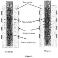
- the alumina bath works as a heat exchanger. Firstly, the bath heats up the reactor to the desired reaction temperature (see "Start-up" in Figure 2 ).
- the bath Since the H 2 conversion and Cu oxidation reactions are highly exothermic, however, the bath also works as a cooler during these processes (charge exhaustion and regeneration), preventing the reactor from overheating (see “Process” in Figure 2 ). When the H 2 conversion reaction is still taking place, but not sufficiently to heat up the reactor to its optimal working temperature, the bath resumes its heating function to keep the temperature of the reactor in the desired range (see “Start-up” in Figure 2 ).
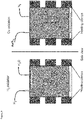
- FIG. 3 shows such an arrangement, with three heating bands displayed for illustrative purposes.
- the bands may be in the form of a single helical band which runs along at least part of the length of the reactor.
- H 2 gas from the dissolution of a metal is introduced via a first conduit which passes the gas to the bottom of the reactor (as shown). The gas passes through the bed of CuO, and reacts therewith leading to the production of gaseous water.
- the gaseous water exits through a venting conduit positioned towards the top of the reactor (as shown).
- a venting conduit positioned towards the top of the reactor (as shown).
- a mixture of air and nitrogen is introduced through the first conduit.
- the oxygen in the air reacts with the partially- or fully-spent CuO bed, so as to reoxidise the Cu present therein.
- the waste nitrogen gas exits the reactor through the venting conduit.
- a number of cycles of H 2 conversion and oxidant regeneration were performed using a process according to the invention.
- the cycles were performed using solid aluminium 'targets' as the metal for dissolution.
- Twenty cycles were performed, with the dissolution of a total amount of Al equivalent to more than 200 U-Al targets.
- the experimental set-up mimicked the current process line in a Mo-99 production facility.
- the number of Al 'targets' dissolved was equivalent to the maximum amount of targets allowed in the production facility employed.
- the initial temperature of the CuO reactor was 200°C.
- the maximum temperature in the CuO reactor during the conversion and regeneration reactions was within limits which are considered acceptable in current processes for H 2 removal.
- the reactor was heated directly using heating elements in the form of bands surrounding the reactor.
- the amount of CuO material was around 11 kg.
- the lower 1.5 kg part of the CuO bed was diluted 50% by weight with stainless steel pellets
- the average H 2 conversion during the 20 cycles was > 95%.
- the average CuO bed regeneration was > 90%.
Landscapes
- Chemical & Material Sciences (AREA)
- Engineering & Computer Science (AREA)
- Physics & Mathematics (AREA)
- Organic Chemistry (AREA)
- Chemical Kinetics & Catalysis (AREA)
- General Engineering & Computer Science (AREA)
- High Energy & Nuclear Physics (AREA)
- Plasma & Fusion (AREA)
- Inorganic Chemistry (AREA)
- General Chemical & Material Sciences (AREA)
- Health & Medical Sciences (AREA)
- General Health & Medical Sciences (AREA)
- Combustion & Propulsion (AREA)
- Biomedical Technology (AREA)
- Environmental & Geological Engineering (AREA)
- Analytical Chemistry (AREA)
- Oil, Petroleum & Natural Gas (AREA)
- Business, Economics & Management (AREA)
- Emergency Management (AREA)
- Catalysts (AREA)
- Physical Or Chemical Processes And Apparatus (AREA)
- Gas Separation By Absorption (AREA)
- Treating Waste Gases (AREA)
Description
- This invention relates to a process. In particular, it relates to a process for treating hydrogen gas liberated from the acid or alkaline dissolution of a metal. Also described herein isa heating apparatus.
- Acid or alkaline dissolution of a metal liberates hydrogen gas. At standard temperature and pressure, hydrogen gas is a colourless, odourless, tasteless and highly combustible diatomic gas. It reacts with any oxidizing agent. Hydrogen gas reacts vigorously with oxygen to produce water in a highly exothermic reaction. It also reacts spontaneously and violently at room temperature with chlorine and fluorine to form the corresponding hydrogen halides, which are potentially dangerous acids. The highly flammable and explosive properties of hydrogen gas make it a hazardous by-product in many processes.
- Technetium-99m is the most widely used radiometal for medical diagnostic and therapeutic applications. Tc-99m is prepared by decay of Mo-99 in so-called Tc-99m generators. Such a generator typically comprises an aqueous solution of Mo-99 loaded onto an adsorbent (usually alumina). Following decay of the Mo-99 to Tc-99m, which has a lower affinity for the alumina, the Tc-99m may be eluted, typically using a saline solution. For the preparation of Tc-99m generators, a high purity source of Mo-99 is therefore essential.
- In order to obtain Mo-99 of high specific activity, it is commonly prepared by the neutron-induced fission of a U-235 target. U-235 is typically present in a target form of U-metal foil, or constructs of U and Al (e.g., a uranium-aluminium alloy). The fission reaction leads to a proportion of the U-235 being converted to Mo-99, but also leads to a number of impurities in the reactor output. Most known processes for Mo-99 production employ acid or alkaline dissolution of the irradiated target, followed by purification of the Mo-99 product. Apart from the solid and liquid impurities, which include Cs, Sr, Ru, Zr, Te, Ba, Al and alkaline and alkaline earth metals, the reaction also produces hydrogen gas. Due to the highly inflammable and explosive properties of hydrogen gas, one of the most important off-gas treatments in the Mo-99 production process is the oxidation of hydrogen gas to form water.
2 H2(g) + O2(g) → 2 H2O(l)
- In most known Mo-99 production processes, the oxidation of hydrogen gas is carried out in the presence of copper (II) oxide (CuO) in the following irreversible reaction:
CuO+H2 → Cu0 + H2O
- This process, first developed by Sameh and Ache in 1987 (Sameh and Ache, 1987 Radiochim. Acta 41,65), is performed in a so-called "CuO oven", which is a fixed-bed chemical reactor. After the dissolution of the irradiated targets, the evolved hydrogen is passed over hot CuO in the CuO oven to oxidise the hydrogen to water. The water vapour is then condensed. This reaction is a typical gas/solid reaction, during which the reaction front moves through the reactor until all CuO is consumed.
- A typical CuO reactor bed weighs significantly more than 10kg and runs at a temperature range of 360-400 °C (targeting a reaction temperature of 385 °C). The heating of the CuO bed is conventionally done by means of a heating plate, located beneath the CuO oven. It is not optimal, taking 24 hours to reach steady state conditions.
- The CuO reactor bed is projected to be completely spent after the dissolution of a certain number of targets (or number of production runs). In a larger Mo-99 production facility, e.g., which enables the processing of more than 6 targets per run, the life time of this CuO reactor is reduced to a smaller number of runs, for example 8 runs.
- Therefore, there is a need for the development of a reactor with a prolonged life time for the treatment of hydrogen gas.
-
US2005/0220689 A1 discloses a method of purifying helium gas by extracting hydrogen and other impurities from a helium gas stream. The method comprises 1) passing the gas stream over a first catalytic adsorber module containing a Cu-CuO mixture, in which hydrogen and carbon monoxide are oxidised into water and carbon dioxide, respectively, and CuO is reduced to Cu, 2) passing the gas stream resulting from step 1), along with oxygen gas, into an oxidation catalyst to convert methane and/or tritium into carbon dioxide and/or water, respectively, and 3) passing the gas stream resulting from step 2), which contains excess oxygen, into a second catalytic adsorber module containing a Cu-CuO mixture, in which the oxygen gas is used to oxidise Cu into CuO. Once the CuO in the first catalytic adsorber is consumed, the order in which the first and the second catalytic adsorbers are connected in the flow path of the gas stream is switched round such that the CuO generated in the second adsorber is used for the oxidation of hydrogen and carbon monoxide, and the Cu in the first adsorber is used to remove the excess oxygen from the purified helium gas stream. - However, this process relates to extraction of hydrogen from a gas stream comprising a number of other components and requires the use of two separate reactors containing Cu-CuO mixtures, which adds to the cost of the process. In addition, similar to hydrogen (i.e., 1H) gas, tritium is a highly explosive gas. The addition of oxygen to a gas stream containing tritium can potentially be hazardous. Therefore, there is a need for the development of a simple method for the treatment of hydrogen using an oxidising agent, during which the oxidising agent is regenerated so as to prolong the use thereof.
- In accordance with a first aspect of the present invention, there is provided a process of treating hydrogen gas liberated from the acid or alkaline dissolution of a metal, the process comprising a step of passing the liberated hydrogen gas through a reactor containing an oxidising agent for oxidation of the hydrogen gas into water, wherein the oxidizing agent comprises a metal oxide finely dispersed on an inert carrier and/or diluted with an inert, thermally-conductive diluent.
- In a preferred embodiment, a step of regenerating the oxidising agent is carried out after each oxidation step. By carrying out a step of regenerating the oxidising agent frequently, such as after each oxidation step, the amount of the oxidising agent initially contained in the reactor can be reduced. Accordingly, the reactor can be scaled down, for example, to around 11 or 12 kg for oxidising the same amount of hydrogen gas. The reduction in the size of the reactor not only allows an easier handling charge/discharge operation but also reduces the time for the reactor to heat up or reach steady state conditions from presently 24 hours to about 3 hours, thereby reducing the cost of the process.
- A further advantage of the process according to the present invention is that the oxidation reaction of hydrogen gas can potentially be conducted at lower temperatures, such as at around 200°C, with regeneration also at around 200 °C. This is particularly the case when a finely dispersed oxidising agent, such as the BASF catalyst materials mentioned herein, is used. Such finely dispersed systems are more active than those used in known processes. The oxidation reaction used for the regeneration of the oxidising agent is, in certain embodiments, highly exothermic. Therefore, the heat given off from the regeneration reaction can be used to heat or maintain the temperature of the reactor. This further reduces the cost of the process.
- The oxidising agent is a metal oxide, such as copper oxide, such as copper (II) oxide, which is converted to copper metal during the process.
- The copper oxide, such as copper (II) oxide, is finely dispersed on the surface of an inert carrier, such as in the Puristar® R3-11G and R3-17 catalysts from BASF (BASF SE, Ludwigshafen, Germany). Alternatively or in addition, the oxidising agent, such as copper oxide, is diluted (either in bulk form or in a finely dispersed form) with an inert, thermally-conductive diluent, such as stainless steel pellets. The diluent helps to prevent uncontrolled heating of the bed of oxidising agent as a result of the heat given out by the exothermic reaction.
- A further advantage of using the finely dispersed oxidising agents, such as the BASF materials mentioned above, is that higher yields are achieved during the regeneration process than with bulk metal oxide (e.g., CuO) material.
- In certain embodiments, the step of regenerating the oxidising agent comprises passing a gas containing oxygen through the reactor containing the oxidising agent to be regenerated. For example, air or air in combination with nitrogen gas can be used.
- Since the gas containing oxygen used for the regeneration step is not mixed with the hydrogen gas, the present invention ensures that potential hazards caused by the highly explosive nature of the hydrogen gas are kept to a minimum.
- In some embodiments, the metal, the dissolution of which liberates the hydrogen gas, comprises uranium, optionally in combination with one or more other metals, for example a uranium-aluminium alloy.
- In some embodiments, the reactor containing the oxidising agent is at least partially immersed in an alumina bath. Optionally, the reactor is completely immersed in an alumina bath.
- The term "alumina bath" refers to a vessel containing a quantity of alumina (Al2O3), which may be used as a means for regulating the temperature of a reactor immersed therein. The bath may take the form of a substantially cylindrical or cuboidal container. The outer walls of the bath are preferably formed of metal, e.g., stainless steel or aluminium. The alumina may form a lining within the container and define a cavity into which a reactor may be placed.
- In a particular embodiment, the alumina bath is supplied with one or more optionally external heating elements. The relatively high thermal conductivity of alumina allows heat from the heating elements to be efficiently passed to a reactor immersed in the bath. Equally, during the highly exothermic process of the H2 conversion and reactor regeneration steps, the alumina helps to conduct heat away from the reactor, thereby preventing it from overheating.
- Whether or not an alumina bath is employed as described above, the reactor may also (or alternatively) be heated by means of one or more heating elements positioned in contact with the reactor. The heating elements (those in contact with the reactor, or those associated with the alumina bath) may conveniently be electrical heating elements.
- Also described herein is an apparatus for carrying out a process according to the first aspect, the apparatus comprising a reactor containing an oxidising agent for the oxidation of hydrogen gas into water, wherein the reactor is at least partially immersed in an alumina bath.
- In a preferred example of said apparatus (not according to the invention), the alumina bath is supplied with one or more heating elements. The heating elements are preferably external to the alumina bath.
- In some examples of said apparatus (not according to the invention), the oxidising agent is copper oxide, such as copper (II) oxide, finely dispersed on the surface of an inert support, such as in the Puristar® R3-11G and R3-17 catalysts from BASF. Alternatively or in addition, the oxidising agent may be diluted (either in bulk form or in a finely dispersed form) with an inert, thermally-conductive diluent, such as stainless steel pellets. Also described herein is a heating apparatus comprising an alumina bath supplied with one or more optionally external heating elements, wherein the alumina bath defines a cavity into which a vessel to be heated may be placed in use.
- In a preferred embodiment of the first aspect, the metal oxide comprises copper oxide, such as copper (II) oxide. More preferably, the copper oxide finely dispersed on an inert carrier comprises the Puristar® R3-11G and/or R3-17 catalysts from BASF. The inert diluent may comprise stainless steel pellets.
- As mentioned above, the use of a finely dispersed oxidising agent, such as the specified BASF materials, gives the advantage that a lower temperature (around 200 °C) can be used for the oxidation reaction. While R3-11 is known to be usable at temperatures of 200 °C or more, R3-17 is indicated by the manufacturer for use (in different applications) at temperatures not exceeding 100 °C. It has been found that R3-17 is capable of use in the processes of the present invention at around 200 °C with no deleterious effects to the material.
- In some embodiments, the process further comprises a step of regenerating the oxidising agent.
- A further advantage of using the finely dispersed oxidising agents is that higher yields are achieved during the regeneration process than with bulk metal oxide (e.g., CuO) material.
- The invention will now be described in more detail by way of example only, and with reference to the following figures:
-
Figure 1 shows a schematic diagram of an exemplary process of the invention, employed during Mo-99 production; -
Figure 2 shows a schematic diagram of the heat transfer between an alumina bath heating apparatus and a reactor containing an oxidising agent for the oxidation of hydrogen gas into water; and -
Figure 3 shows a schematic, cross-sectional diagram of an apparatus for carrying out a process according to the invention, in which the reactor vessel containing the oxidising agent (in this case, CuO) is heated directly by means of electrically-heated clamps/bands. - As shown in
Figure 1 , following the dissolution of an irradiated uranium-aluminium target, the hydrogen gas liberated in the dissolver is passed into a CuO reactor, in which the hydrogen gas is oxidised into water while the CuO is converted into Cu. After each oxidation step (and before the next round of oxidation begins), a stream of air-containing nitrogen gas (N2/air) is fed into the CuO reactor to oxidise Cu in order to regenerate CuO. - The CuO reactor can be heated using a heating apparatus as described herein and shown in
Figure 2 . Such a heating apparatus can improve heat transfer during the operation of the reactor. The CuO reactor can be immersed in an alumina bath fitted with one or more external heating elements (seeFigure 2 ). The heating elements may be present as one or more collars or jackets around the bath, or as a heating coil. The heating elements are preferably electrically heated. The alumina bath works as a heat exchanger. Firstly, the bath heats up the reactor to the desired reaction temperature (see "Start-up" inFigure 2 ). Since the H2 conversion and Cu oxidation reactions are highly exothermic, however, the bath also works as a cooler during these processes (charge exhaustion and regeneration), preventing the reactor from overheating (see "Process" inFigure 2 ). When the H2 conversion reaction is still taking place, but not sufficiently to heat up the reactor to its optimal working temperature, the bath resumes its heating function to keep the temperature of the reactor in the desired range (see "Start-up" inFigure 2 ). - As an alternative to the use of an alumina bath as shown in
Figure 2 , it is possible to heat the reactor directly using one or more heated clamps or bands positioned in contact with the reactor.Figure 3 shows such an arrangement, with three heating bands displayed for illustrative purposes. It will be appreciated that the bands may be in the form of a single helical band which runs along at least part of the length of the reactor. In the left part ofFigure 3 (H2 oxidation), H2 gas from the dissolution of a metal is introduced via a first conduit which passes the gas to the bottom of the reactor (as shown). The gas passes through the bed of CuO, and reacts therewith leading to the production of gaseous water. The gaseous water exits through a venting conduit positioned towards the top of the reactor (as shown). In the right part of the Figure (Cu oxidation), a mixture of air and nitrogen is introduced through the first conduit. The oxygen in the air reacts with the partially- or fully-spent CuO bed, so as to reoxidise the Cu present therein. The waste nitrogen gas exits the reactor through the venting conduit. - A number of cycles of H2 conversion and oxidant regeneration were performed using a process according to the invention. The cycles were performed using solid aluminium 'targets' as the metal for dissolution. Twenty cycles were performed, with the dissolution of a total amount of Al equivalent to more than 200 U-Al targets. The experimental set-up mimicked the current process line in a Mo-99 production facility. In each cycle, the number of Al 'targets' dissolved was equivalent to the maximum amount of targets allowed in the production facility employed.
- The initial temperature of the CuO reactor was 200°C. The maximum temperature in the CuO reactor during the conversion and regeneration reactions was within limits which are considered acceptable in current processes for H2 removal. The reactor was heated directly using heating elements in the form of bands surrounding the reactor. The amount of CuO material was around 11 kg. In addition, the lower 1.5 kg part of the CuO bed was diluted 50% by weight with stainless steel pellets
- The average H2 conversion during the 20 cycles was > 95%. During the regeneration phase of the cycles, the average CuO bed regeneration was > 90%.
Claims (13)
- A process of treating hydrogen gas liberated from the acid or alkaline dissolution of a metal, the process comprising a step of passing the liberated hydrogen gas through a reactor containing an oxidising agent for oxidation of the hydrogen gas into water, wherein the oxidizing agent comprises a metal oxide finely dispersed on an inert carrier and/or diluted with an inert, thermally-conductive diluent.
- A process according to claim 1, wherein the metal oxide comprises copper oxide.
- A process according to claim 1 or claim 2, wherein the inert, thermally-conductive diluent comprises stainless steel pellets.
- A process according to any one of claims 1 to 3, wherein the oxidation reaction is conducted at a temperature of 200 °C.
- A process according to any one of claims 1 to 4, further comprising a step of regenerating the oxidising agent.
- A process according to claim 5, wherein the step of regenerating the oxidising agent is carried out after each oxidation step.
- A process according to claims 5 or 6, wherein the step of regenerating the oxidising agent comprises passing a gas containing oxygen through the reactor containing the oxidising agent.
- A process according to claim 7, wherein the gas containing oxygen is air or air in combination with nitrogen gas.
- A process according to any one of claims 5 to 8, wherein the step of regenerating the oxidising agent is conducted at a temperature of 200 °C.
- A process according to any one of claims 1 to 8, wherein the metal, the dissolution of which liberates hydrogen gas, comprises uranium.
- A process according to claim 10, wherein the metal is a uranium-aluminium alloy.
- A process according to any one of claims 1 to 11, wherein the reactor containing the oxidising agent is partially immersed in an alumina bath.
- A process according to any one of claims 1 to 11, wherein the reactor containing the oxidising agent is completely immersed in an alumina bath.
Applications Claiming Priority (3)
| Application Number | Priority Date | Filing Date | Title |
|---|---|---|---|
| GB201100504A GB201100504D0 (en) | 2011-01-12 | 2011-01-12 | Process |
| EP12702647.4A EP2663523B1 (en) | 2011-01-12 | 2012-01-11 | Process and apparatus for treating a gas stream |
| PCT/US2012/020906 WO2012097045A1 (en) | 2011-01-12 | 2012-01-11 | Process and apparatus for treating a gas stream |
Related Parent Applications (2)
| Application Number | Title | Priority Date | Filing Date |
|---|---|---|---|
| EP12702647.4A Division-Into EP2663523B1 (en) | 2011-01-12 | 2012-01-11 | Process and apparatus for treating a gas stream |
| EP12702647.4A Division EP2663523B1 (en) | 2011-01-12 | 2012-01-11 | Process and apparatus for treating a gas stream |
Publications (2)
| Publication Number | Publication Date |
|---|---|
| EP3424876A1 EP3424876A1 (en) | 2019-01-09 |
| EP3424876B1 true EP3424876B1 (en) | 2022-05-18 |
Family
ID=43664140
Family Applications (2)
| Application Number | Title | Priority Date | Filing Date |
|---|---|---|---|
| EP12702647.4A Active EP2663523B1 (en) | 2011-01-12 | 2012-01-11 | Process and apparatus for treating a gas stream |
| EP18189206.8A Active EP3424876B1 (en) | 2011-01-12 | 2012-01-11 | Process for treating a gas stream |
Family Applications Before (1)
| Application Number | Title | Priority Date | Filing Date |
|---|---|---|---|
| EP12702647.4A Active EP2663523B1 (en) | 2011-01-12 | 2012-01-11 | Process and apparatus for treating a gas stream |
Country Status (11)
| Country | Link |
|---|---|
| US (2) | US8790606B2 (en) |
| EP (2) | EP2663523B1 (en) |
| KR (1) | KR101807343B1 (en) |
| AU (1) | AU2012205625B2 (en) |
| BR (1) | BR112013017755B1 (en) |
| CA (1) | CA2824424C (en) |
| ES (1) | ES2700516T3 (en) |
| GB (1) | GB201100504D0 (en) |
| HU (1) | HUE041579T2 (en) |
| PL (2) | PL2663523T3 (en) |
| WO (1) | WO2012097045A1 (en) |
Families Citing this family (2)
| Publication number | Priority date | Publication date | Assignee | Title |
|---|---|---|---|---|
| GB201100504D0 (en) | 2011-01-12 | 2011-02-23 | Mallinckrodt Inc | Process |
| JP6901285B2 (en) * | 2017-03-08 | 2021-07-14 | 株式会社東芝 | Hydrogen removal device |
Family Cites Families (17)
| Publication number | Priority date | Publication date | Assignee | Title |
|---|---|---|---|---|
| US2863729A (en) * | 1953-02-27 | 1958-12-09 | Harold F Mcduffie | Combination of hydrogen and oxygen |
| GB1158861A (en) | 1965-07-16 | 1969-07-23 | United Aircraft Corp | Improvements in and relating to a Mold Heater |
| US3630956A (en) * | 1969-04-01 | 1971-12-28 | Air Prod & Chem | Method of producing gases with controlled concentrations of water vapor |
| US3630959A (en) | 1969-06-04 | 1971-12-28 | Standard Oil Co Ohio | Carbonization of bituminous coals |
| US3937796A (en) * | 1972-01-10 | 1976-02-10 | Universal Oil Products Company | Recuperative thermal recombining system for handling loss of coolant |
| US3798178A (en) * | 1972-02-17 | 1974-03-19 | Dow Chemical Co | Self-regenerative dehydrogenation catalyst |
| DE2633113C2 (en) * | 1976-07-23 | 1984-08-30 | Kernforschungszentrum Karlsruhe Gmbh, 7500 Karlsruhe | Procedure for avoiding hazards arising from accidents on water-cooled nuclear reactors |
| DE3428877A1 (en) * | 1984-08-04 | 1986-02-13 | Kernforschungszentrum Karlsruhe Gmbh, 7500 Karlsruhe | METHOD FOR SEPARATING LARGE AMOUNTS OF URANIUM FROM LITTLE AMOUNTS OF RADIOACTIVE FUSE PRODUCTS EXISTING IN AQUEOUS BASIC SOLUTIONS CONTAINING CARBONATE |
| KR900702315A (en) * | 1988-10-19 | 1990-12-06 | 원본미기재 | Heat pipes using hydrogen oxidation means |
| DE3927959A1 (en) * | 1989-08-24 | 1991-02-28 | Gemeinschaftskernkraftwerk Nec | METHOD FOR AVOIDING LOCAL HYDROGEN CONCENTRATIONS IN SAFETY CONTAINERS OF REACTORS |
| EP0469260A1 (en) * | 1990-07-30 | 1992-02-05 | Abb Air Preheater, Inc. | Heat pipe heat exchanger and heat pipe therefor |
| ES2079939T3 (en) * | 1993-12-13 | 1996-01-16 | Anlagen Und Reaktorsicherheit | DEVICE FOR THE ELIMINATION OF FREE HYDROGEN FROM A GASEOUS MIXTURE CONTAINING HYDROGEN AND OXYGEN. |
| US20030193988A1 (en) * | 2002-04-16 | 2003-10-16 | Calvin Bates | Method and apparatus for determining the concentration of components of molten baths |
| US6855241B2 (en) * | 2002-04-22 | 2005-02-15 | Forrest M. Palmer | Process and apparatus for smelting aluminum |
| US7455818B2 (en) | 2002-10-02 | 2008-11-25 | Areva Np Gmbh | Method for treating a flow of gas and gas treatment system |
| EP1674424B1 (en) * | 2004-12-23 | 2011-11-23 | Hoppecke Technologies GmbH & Co. KG | Recombination Device |
| GB201100504D0 (en) | 2011-01-12 | 2011-02-23 | Mallinckrodt Inc | Process |
-
2011
- 2011-01-12 GB GB201100504A patent/GB201100504D0/en not_active Ceased
-
2012
- 2012-01-11 CA CA2824424A patent/CA2824424C/en active Active
- 2012-01-11 PL PL12702647T patent/PL2663523T3/en unknown
- 2012-01-11 AU AU2012205625A patent/AU2012205625B2/en active Active
- 2012-01-11 ES ES12702647T patent/ES2700516T3/en active Active
- 2012-01-11 US US13/978,725 patent/US8790606B2/en active Active
- 2012-01-11 EP EP12702647.4A patent/EP2663523B1/en active Active
- 2012-01-11 WO PCT/US2012/020906 patent/WO2012097045A1/en not_active Ceased
- 2012-01-11 KR KR1020137020944A patent/KR101807343B1/en active Active
- 2012-01-11 HU HUE12702647A patent/HUE041579T2/en unknown
- 2012-01-11 EP EP18189206.8A patent/EP3424876B1/en active Active
- 2012-01-11 PL PL18189206.8T patent/PL3424876T3/en unknown
- 2012-01-11 BR BR112013017755-1A patent/BR112013017755B1/en active IP Right Grant
-
2014
- 2014-06-26 US US14/316,149 patent/US9238212B2/en active Active
Also Published As
| Publication number | Publication date |
|---|---|
| ES2700516T3 (en) | 2019-02-18 |
| US20140308029A1 (en) | 2014-10-16 |
| KR101807343B1 (en) | 2017-12-08 |
| WO2012097045A1 (en) | 2012-07-19 |
| BR112013017755B1 (en) | 2021-03-09 |
| CA2824424C (en) | 2019-07-16 |
| AU2012205625A1 (en) | 2014-09-18 |
| EP2663523A1 (en) | 2013-11-20 |
| US8790606B2 (en) | 2014-07-29 |
| AU2012205625B2 (en) | 2015-07-23 |
| PL2663523T3 (en) | 2019-06-28 |
| RU2013137381A (en) | 2015-02-20 |
| US20130294993A1 (en) | 2013-11-07 |
| US9238212B2 (en) | 2016-01-19 |
| CA2824424A1 (en) | 2012-07-19 |
| BR112013017755A2 (en) | 2016-10-11 |
| EP2663523B1 (en) | 2018-10-10 |
| GB201100504D0 (en) | 2011-02-23 |
| PL3424876T3 (en) | 2022-08-16 |
| EP3424876A1 (en) | 2019-01-09 |
| HUE041579T2 (en) | 2019-05-28 |
| KR20140043885A (en) | 2014-04-11 |
Similar Documents
| Publication | Publication Date | Title |
|---|---|---|
| WO2014102223A1 (en) | Method and apparatus for producing metal by electrolytic reduction | |
| JP7687618B2 (en) | Method for producing methane | |
| JP6678194B2 (en) | Method and apparatus for generating hydrogen gas | |
| CN102616868B (en) | Method for preparing solid nitrosyl ruthenium nitrate by using dead catalyst containing ruthenium | |
| WO2001060743A1 (en) | Method for producing chlorine | |
| EP3239098B1 (en) | Method for catalytically oxidizing hydrogen chloride to prepare chlorine gas | |
| JP2010269239A (en) | Ammonia oxidation / decomposition catalyst | |
| JPWO2012020834A1 (en) | Hydrogen production method and apparatus | |
| EP2663523B1 (en) | Process and apparatus for treating a gas stream | |
| CN107952436A (en) | A kind of preparing chlorine by oxidizing hydrogen chloride copper-zirconium based catalyst and its preparation method and application | |
| KR20230054385A (en) | How to recover nickel from waste battery material | |
| KR102744450B1 (en) | Method for producing bromine pentafluoride | |
| RU2588219C2 (en) | Method and device for processing gas flow | |
| KR102544654B1 (en) | Method for producing tungsten hexafluoride | |
| US20100111823A1 (en) | Methods and systems for producing hydrogen and system for producing power | |
| ZA200504995B (en) | Fluorine production method | |
| JPS5943401B2 (en) | How to recombine oxygen and hydrogen | |
| JP4016532B2 (en) | Reagent for decomposition of nitrogen fluoride and decomposition method | |
| CN119851999A (en) | Method for removing and purifying radioactive methane in hydrogen-containing waste gas in nuclear industry | |
| JP2024092355A (en) | Method for post-treating metal catalyst | |
| JP5189342B2 (en) | Gas processing method | |
| JP5041769B2 (en) | Startup method | |
| JP2024098264A (en) | Hydrogen gas production method and device | |
| CN121496173A (en) | A method for separating metal fission products and uranium oxides by chlorination-reduction synergistic liquid metal extraction | |
| JP2011042513A (en) | Method for producing hydrogen |
Legal Events
| Date | Code | Title | Description |
|---|---|---|---|
| PUAI | Public reference made under article 153(3) epc to a published international application that has entered the european phase |
Free format text: ORIGINAL CODE: 0009012 |
|
| STAA | Information on the status of an ep patent application or granted ep patent |
Free format text: STATUS: THE APPLICATION HAS BEEN PUBLISHED |
|
| AC | Divisional application: reference to earlier application |
Ref document number: 2663523 Country of ref document: EP Kind code of ref document: P |
|
| AK | Designated contracting states |
Kind code of ref document: A1 Designated state(s): AL AT BE BG CH CY CZ DE DK EE ES FI FR GB GR HR HU IE IS IT LI LT LU LV MC MK MT NL NO PL PT RO RS SE SI SK SM TR |
|
| STAA | Information on the status of an ep patent application or granted ep patent |
Free format text: STATUS: REQUEST FOR EXAMINATION WAS MADE |
|
| 17P | Request for examination filed |
Effective date: 20190704 |
|
| RBV | Designated contracting states (corrected) |
Designated state(s): AL AT BE BG CH CY CZ DE DK EE ES FI FR GB GR HR HU IE IS IT LI LT LU LV MC MK MT NL NO PL PT RO RS SE SI SK SM TR |
|
| RAP1 | Party data changed (applicant data changed or rights of an application transferred) |
Owner name: CURIUM US LLC |
|
| STAA | Information on the status of an ep patent application or granted ep patent |
Free format text: STATUS: EXAMINATION IS IN PROGRESS |
|
| 17Q | First examination report despatched |
Effective date: 20210621 |
|
| GRAP | Despatch of communication of intention to grant a patent |
Free format text: ORIGINAL CODE: EPIDOSNIGR1 |
|
| STAA | Information on the status of an ep patent application or granted ep patent |
Free format text: STATUS: GRANT OF PATENT IS INTENDED |
|
| INTG | Intention to grant announced |
Effective date: 20211210 |
|
| GRAS | Grant fee paid |
Free format text: ORIGINAL CODE: EPIDOSNIGR3 |
|
| GRAA | (expected) grant |
Free format text: ORIGINAL CODE: 0009210 |
|
| STAA | Information on the status of an ep patent application or granted ep patent |
Free format text: STATUS: THE PATENT HAS BEEN GRANTED |
|
| AC | Divisional application: reference to earlier application |
Ref document number: 2663523 Country of ref document: EP Kind code of ref document: P |
|
| AK | Designated contracting states |
Kind code of ref document: B1 Designated state(s): AL AT BE BG CH CY CZ DE DK EE ES FI FR GB GR HR HU IE IS IT LI LT LU LV MC MK MT NL NO PL PT RO RS SE SI SK SM TR |
|
| REG | Reference to a national code |
Ref country code: GB Ref legal event code: FG4D |
|
| REG | Reference to a national code |
Ref country code: CH Ref legal event code: EP |
|
| REG | Reference to a national code |
Ref country code: IE Ref legal event code: FG4D |
|
| REG | Reference to a national code |
Ref country code: DE Ref legal event code: R096 Ref document number: 602012078262 Country of ref document: DE |
|
| REG | Reference to a national code |
Ref country code: AT Ref legal event code: REF Ref document number: 1493060 Country of ref document: AT Kind code of ref document: T Effective date: 20220615 |
|
| REG | Reference to a national code |
Ref country code: NL Ref legal event code: FP |
|
| REG | Reference to a national code |
Ref country code: LT Ref legal event code: MG9D |
|
| REG | Reference to a national code |
Ref country code: AT Ref legal event code: MK05 Ref document number: 1493060 Country of ref document: AT Kind code of ref document: T Effective date: 20220518 |
|
| PG25 | Lapsed in a contracting state [announced via postgrant information from national office to epo] |
Ref country code: SE Free format text: LAPSE BECAUSE OF FAILURE TO SUBMIT A TRANSLATION OF THE DESCRIPTION OR TO PAY THE FEE WITHIN THE PRESCRIBED TIME-LIMIT Effective date: 20220518 Ref country code: PT Free format text: LAPSE BECAUSE OF FAILURE TO SUBMIT A TRANSLATION OF THE DESCRIPTION OR TO PAY THE FEE WITHIN THE PRESCRIBED TIME-LIMIT Effective date: 20220919 Ref country code: NO Free format text: LAPSE BECAUSE OF FAILURE TO SUBMIT A TRANSLATION OF THE DESCRIPTION OR TO PAY THE FEE WITHIN THE PRESCRIBED TIME-LIMIT Effective date: 20220818 Ref country code: LT Free format text: LAPSE BECAUSE OF FAILURE TO SUBMIT A TRANSLATION OF THE DESCRIPTION OR TO PAY THE FEE WITHIN THE PRESCRIBED TIME-LIMIT Effective date: 20220518 Ref country code: HR Free format text: LAPSE BECAUSE OF FAILURE TO SUBMIT A TRANSLATION OF THE DESCRIPTION OR TO PAY THE FEE WITHIN THE PRESCRIBED TIME-LIMIT Effective date: 20220518 Ref country code: GR Free format text: LAPSE BECAUSE OF FAILURE TO SUBMIT A TRANSLATION OF THE DESCRIPTION OR TO PAY THE FEE WITHIN THE PRESCRIBED TIME-LIMIT Effective date: 20220819 Ref country code: FI Free format text: LAPSE BECAUSE OF FAILURE TO SUBMIT A TRANSLATION OF THE DESCRIPTION OR TO PAY THE FEE WITHIN THE PRESCRIBED TIME-LIMIT Effective date: 20220518 Ref country code: ES Free format text: LAPSE BECAUSE OF FAILURE TO SUBMIT A TRANSLATION OF THE DESCRIPTION OR TO PAY THE FEE WITHIN THE PRESCRIBED TIME-LIMIT Effective date: 20220518 Ref country code: BG Free format text: LAPSE BECAUSE OF FAILURE TO SUBMIT A TRANSLATION OF THE DESCRIPTION OR TO PAY THE FEE WITHIN THE PRESCRIBED TIME-LIMIT Effective date: 20220818 Ref country code: AT Free format text: LAPSE BECAUSE OF FAILURE TO SUBMIT A TRANSLATION OF THE DESCRIPTION OR TO PAY THE FEE WITHIN THE PRESCRIBED TIME-LIMIT Effective date: 20220518 |
|
| PG25 | Lapsed in a contracting state [announced via postgrant information from national office to epo] |
Ref country code: RS Free format text: LAPSE BECAUSE OF FAILURE TO SUBMIT A TRANSLATION OF THE DESCRIPTION OR TO PAY THE FEE WITHIN THE PRESCRIBED TIME-LIMIT Effective date: 20220518 Ref country code: LV Free format text: LAPSE BECAUSE OF FAILURE TO SUBMIT A TRANSLATION OF THE DESCRIPTION OR TO PAY THE FEE WITHIN THE PRESCRIBED TIME-LIMIT Effective date: 20220518 Ref country code: IS Free format text: LAPSE BECAUSE OF FAILURE TO SUBMIT A TRANSLATION OF THE DESCRIPTION OR TO PAY THE FEE WITHIN THE PRESCRIBED TIME-LIMIT Effective date: 20220918 |
|
| PG25 | Lapsed in a contracting state [announced via postgrant information from national office to epo] |
Ref country code: SM Free format text: LAPSE BECAUSE OF FAILURE TO SUBMIT A TRANSLATION OF THE DESCRIPTION OR TO PAY THE FEE WITHIN THE PRESCRIBED TIME-LIMIT Effective date: 20220518 Ref country code: SK Free format text: LAPSE BECAUSE OF FAILURE TO SUBMIT A TRANSLATION OF THE DESCRIPTION OR TO PAY THE FEE WITHIN THE PRESCRIBED TIME-LIMIT Effective date: 20220518 Ref country code: RO Free format text: LAPSE BECAUSE OF FAILURE TO SUBMIT A TRANSLATION OF THE DESCRIPTION OR TO PAY THE FEE WITHIN THE PRESCRIBED TIME-LIMIT Effective date: 20220518 Ref country code: EE Free format text: LAPSE BECAUSE OF FAILURE TO SUBMIT A TRANSLATION OF THE DESCRIPTION OR TO PAY THE FEE WITHIN THE PRESCRIBED TIME-LIMIT Effective date: 20220518 Ref country code: DK Free format text: LAPSE BECAUSE OF FAILURE TO SUBMIT A TRANSLATION OF THE DESCRIPTION OR TO PAY THE FEE WITHIN THE PRESCRIBED TIME-LIMIT Effective date: 20220518 Ref country code: CZ Free format text: LAPSE BECAUSE OF FAILURE TO SUBMIT A TRANSLATION OF THE DESCRIPTION OR TO PAY THE FEE WITHIN THE PRESCRIBED TIME-LIMIT Effective date: 20220518 |
|
| REG | Reference to a national code |
Ref country code: DE Ref legal event code: R097 Ref document number: 602012078262 Country of ref document: DE |
|
| PLBE | No opposition filed within time limit |
Free format text: ORIGINAL CODE: 0009261 |
|
| STAA | Information on the status of an ep patent application or granted ep patent |
Free format text: STATUS: NO OPPOSITION FILED WITHIN TIME LIMIT |
|
| PG25 | Lapsed in a contracting state [announced via postgrant information from national office to epo] |
Ref country code: AL Free format text: LAPSE BECAUSE OF FAILURE TO SUBMIT A TRANSLATION OF THE DESCRIPTION OR TO PAY THE FEE WITHIN THE PRESCRIBED TIME-LIMIT Effective date: 20220518 |
|
| 26N | No opposition filed |
Effective date: 20230221 |
|
| PG25 | Lapsed in a contracting state [announced via postgrant information from national office to epo] |
Ref country code: SI Free format text: LAPSE BECAUSE OF FAILURE TO SUBMIT A TRANSLATION OF THE DESCRIPTION OR TO PAY THE FEE WITHIN THE PRESCRIBED TIME-LIMIT Effective date: 20220518 |
|
| P01 | Opt-out of the competence of the unified patent court (upc) registered |
Effective date: 20230529 |
|
| REG | Reference to a national code |
Ref country code: CH Ref legal event code: PL |
|
| PG25 | Lapsed in a contracting state [announced via postgrant information from national office to epo] |
Ref country code: LU Free format text: LAPSE BECAUSE OF NON-PAYMENT OF DUE FEES Effective date: 20230111 |
|
| PG25 | Lapsed in a contracting state [announced via postgrant information from national office to epo] |
Ref country code: LI Free format text: LAPSE BECAUSE OF NON-PAYMENT OF DUE FEES Effective date: 20230131 Ref country code: CH Free format text: LAPSE BECAUSE OF NON-PAYMENT OF DUE FEES Effective date: 20230131 |
|
| PG25 | Lapsed in a contracting state [announced via postgrant information from national office to epo] |
Ref country code: IT Free format text: LAPSE BECAUSE OF FAILURE TO SUBMIT A TRANSLATION OF THE DESCRIPTION OR TO PAY THE FEE WITHIN THE PRESCRIBED TIME-LIMIT Effective date: 20220518 Ref country code: IE Free format text: LAPSE BECAUSE OF NON-PAYMENT OF DUE FEES Effective date: 20230111 |
|
| PG25 | Lapsed in a contracting state [announced via postgrant information from national office to epo] |
Ref country code: MC Free format text: LAPSE BECAUSE OF FAILURE TO SUBMIT A TRANSLATION OF THE DESCRIPTION OR TO PAY THE FEE WITHIN THE PRESCRIBED TIME-LIMIT Effective date: 20220518 |
|
| PG25 | Lapsed in a contracting state [announced via postgrant information from national office to epo] |
Ref country code: MC Free format text: LAPSE BECAUSE OF FAILURE TO SUBMIT A TRANSLATION OF THE DESCRIPTION OR TO PAY THE FEE WITHIN THE PRESCRIBED TIME-LIMIT Effective date: 20220518 |
|
| PG25 | Lapsed in a contracting state [announced via postgrant information from national office to epo] |
Ref country code: BG Free format text: LAPSE BECAUSE OF FAILURE TO SUBMIT A TRANSLATION OF THE DESCRIPTION OR TO PAY THE FEE WITHIN THE PRESCRIBED TIME-LIMIT Effective date: 20220518 |
|
| PG25 | Lapsed in a contracting state [announced via postgrant information from national office to epo] |
Ref country code: BG Free format text: LAPSE BECAUSE OF FAILURE TO SUBMIT A TRANSLATION OF THE DESCRIPTION OR TO PAY THE FEE WITHIN THE PRESCRIBED TIME-LIMIT Effective date: 20220518 |
|
| PG25 | Lapsed in a contracting state [announced via postgrant information from national office to epo] |
Ref country code: CY Free format text: LAPSE BECAUSE OF FAILURE TO SUBMIT A TRANSLATION OF THE DESCRIPTION OR TO PAY THE FEE WITHIN THE PRESCRIBED TIME-LIMIT; INVALID AB INITIO Effective date: 20120111 |
|
| PG25 | Lapsed in a contracting state [announced via postgrant information from national office to epo] |
Ref country code: HU Free format text: LAPSE BECAUSE OF FAILURE TO SUBMIT A TRANSLATION OF THE DESCRIPTION OR TO PAY THE FEE WITHIN THE PRESCRIBED TIME-LIMIT; INVALID AB INITIO Effective date: 20120111 |
|
| PG25 | Lapsed in a contracting state [announced via postgrant information from national office to epo] |
Ref country code: TR Free format text: LAPSE BECAUSE OF FAILURE TO SUBMIT A TRANSLATION OF THE DESCRIPTION OR TO PAY THE FEE WITHIN THE PRESCRIBED TIME-LIMIT Effective date: 20220518 |
|
| PGFP | Annual fee paid to national office [announced via postgrant information from national office to epo] |
Ref country code: PL Payment date: 20251218 Year of fee payment: 15 |
|
| PGFP | Annual fee paid to national office [announced via postgrant information from national office to epo] |
Ref country code: NL Payment date: 20260126 Year of fee payment: 15 |
|
| PGFP | Annual fee paid to national office [announced via postgrant information from national office to epo] |
Ref country code: GB Payment date: 20260127 Year of fee payment: 15 |
|
| PGFP | Annual fee paid to national office [announced via postgrant information from national office to epo] |
Ref country code: DE Payment date: 20260128 Year of fee payment: 15 |
|
| PGFP | Annual fee paid to national office [announced via postgrant information from national office to epo] |
Ref country code: BE Payment date: 20260127 Year of fee payment: 15 |
|
| PGFP | Annual fee paid to national office [announced via postgrant information from national office to epo] |
Ref country code: FR Payment date: 20260126 Year of fee payment: 15 |