EP3424794A1 - Collision energy absorption apparatus for rail vehicles - Google Patents
Collision energy absorption apparatus for rail vehicles Download PDFInfo
- Publication number
- EP3424794A1 EP3424794A1 EP16892327.4A EP16892327A EP3424794A1 EP 3424794 A1 EP3424794 A1 EP 3424794A1 EP 16892327 A EP16892327 A EP 16892327A EP 3424794 A1 EP3424794 A1 EP 3424794A1
- Authority
- EP
- European Patent Office
- Prior art keywords
- energy absorption
- tearing
- tube
- kerfs
- collision
- Prior art date
- Legal status (The legal status is an assumption and is not a legal conclusion. Google has not performed a legal analysis and makes no representation as to the accuracy of the status listed.)
- Granted
Links
Images

Classifications
-
- B—PERFORMING OPERATIONS; TRANSPORTING
- B61—RAILWAYS
- B61F—RAIL VEHICLE SUSPENSIONS, e.g. UNDERFRAMES, BOGIES OR ARRANGEMENTS OF WHEEL AXLES; RAIL VEHICLES FOR USE ON TRACKS OF DIFFERENT WIDTH; PREVENTING DERAILING OF RAIL VEHICLES; WHEEL GUARDS, OBSTRUCTION REMOVERS OR THE LIKE FOR RAIL VEHICLES
- B61F19/00—Wheel guards; Bumpers; Obstruction removers or the like
- B61F19/04—Bumpers or like collision guards
-
- B—PERFORMING OPERATIONS; TRANSPORTING
- B61—RAILWAYS
- B61G—COUPLINGS; DRAUGHT AND BUFFING APPLIANCES
- B61G11/00—Buffers
- B61G11/18—Details
-
- B—PERFORMING OPERATIONS; TRANSPORTING
- B64—AIRCRAFT; AVIATION; COSMONAUTICS
- B64C—AEROPLANES; HELICOPTERS
- B64C25/00—Alighting gear
- B64C25/32—Alighting gear characterised by elements which contact the ground or similar surface
- B64C25/58—Arrangements or adaptations of shock-absorbers or springs
- B64C25/62—Spring shock-absorbers; Springs
-
- F—MECHANICAL ENGINEERING; LIGHTING; HEATING; WEAPONS; BLASTING
- F16—ENGINEERING ELEMENTS AND UNITS; GENERAL MEASURES FOR PRODUCING AND MAINTAINING EFFECTIVE FUNCTIONING OF MACHINES OR INSTALLATIONS; THERMAL INSULATION IN GENERAL
- F16F—SPRINGS; SHOCK-ABSORBERS; MEANS FOR DAMPING VIBRATION
- F16F7/00—Vibration-dampers; Shock-absorbers
- F16F7/12—Vibration-dampers; Shock-absorbers using plastic deformation of members
- F16F7/127—Vibration-dampers; Shock-absorbers using plastic deformation of members by a blade element cutting or tearing into a quantity of material; Pultrusion of a filling material
Definitions
- the present disclosure relates to the field of collision energy absorption apparatus, and in particular to a collision energy absorption apparatus for a rail vehicle.
- unmanned areas at both ends of the vehicle are generally designed with weak stiffness and manned areas are designed with strong stiffness, so that the unmanned areas undergo a large plastic deformation during an collision accident of the vehicle to dissipate the collision energy, while the manned areas merely undergo an elastic deformation or small plastic deformation, thereby ensuring the space integrity of the manned areas.
- a load-bearing energy absorbing structure In addition to the function of absorbing collision energy during a vehicle collision accident, the load-bearing energy absorption structure also bears loads in normal applications. The characteristics of this structure at least lie in that it provides a low cost and a simple construction, but needs cumbersome repairs and a high repair cost after collision.
- the dedicated energy absorption structure is mounted on either ends of a vehicle and bears no load in normal applications. These structures dissipate collision energy through plastic deformation thereof only when collision accident of the vehicle occurs.
- the dedicated energy absorption structure is widely used in the crashworthiness design of modern rail vehicles due to its stable deformation, convenient replacement, and low repair cost, etc.
- Dedicated collision energy absorption structures can be known from the following related art documents.
- Patent application CN201010281420.3 relates to a collision buffering energy absorption device, a base plate of the collision buffering energy absorption device is connected to a guide boss, and keep a certain distance away from a friction guide plate; an energy absorption tube with an axial groove surrounds around the guide boss; and a substrate is mounted at the other end of the energy absorption tube.
- the groove may be machined in the outer surface of the energy absorption tube or in the inner surface of the energy absorption tube, and the energy absorption tube may be partially torn at the groove or not torn during assembling.
- the substrate drives the energy absorption tube to move toward the base plate, during the moving, a portion of energy is absorbed through the friction between the energy absorption tube and the guide boss; meanwhile, due to the cross-sectional area of the guide boss becomes larger as the guide boss approaches the base plate, the energy absorption tube is torn at the axial groove at a certain moment, and a portion of the energy is absorbed during tearing; then the torn part of the energy absorption tube is bent to enter a space between the friction guide plate and the base plate, and during the advancing stroke of the torn part, a portion of the energy is absorbed through friction; and eventually the buffering energy absorption effect is achieved.
- This collision buffering energy absorption device is simple in structure, easy to manufacture, and low in cost. Meanwhile, this collision buffering energy absorption device may absorb energy load uniformly, has high capacity, and can serve as good passive safety protection equipment.
- patent CN201310082195.4 also disclosed a novel energy absorption device buffering uniformly.
- the energy absorption device comprises a round pre-torn tube, a guide friction round tube and a punch.
- the round pre-torn tube is a thin-walled metal round tube, and one end of the tube is circular truncated cone in shape and is in the form of a funnel, this end is provided with a cone angle; the other end of the tube, with the guide friction round tube, are fixed on a same panel by adhesive or brazing and are kept coaxial relative to each other.
- the guide friction round tube is slightly longer than the round pre-torn tube in length, in order for the energy absorption device partially cooperates with the punch before the energy absorption device is impacted.
- a tearing slot is provided in the wall of the round pre-torn tube and a tearing opening is provided in an end of the round pre-torn tube.
- the head of the punch is in the form of a circular truncated cone, and the transition between the head and the end of the round pre-torn tube closed to the punch is steady and smooth.
- a through hole interference fitted with the outer wall of the guide friction round tube is provided in the punch and plays a role of axial positioning and absorbing a portion of energy through friction. This device absorbs energy mainly by the bulging resulting from the extruding of the punch into the round pre-torn tube and the following tear of the round tube.
- the round pre-torn tube has an inner diameter between 30 and 80 mm, a wall thickness h1 between 2 and 5 mm, and a length L1 between 60 and 120 mm.
- the tear and curling damage of the round tube is more effective in energy absorption effect than breaking, axial flection or turnover, and the device has the characteristics of long effective stroke and smooth impact force.
- the present disclosure provides a novel collision energy absorption apparatus for rail vehicle.
- This collision energy absorption apparatus is able to significantly reduce the initial impact force peak of the apparatus and the effective stroke can theoretically reach 100%.
- This apparatus may be conveniently mounted at the end of the rail vehicle, and may act the role of dissipating collision kinetic energy during the collision of the vehicle.
- the inner wall and outer wall of a round pre-torn tube are provided with grooves with a certain width.
- the inventors of the present application have found, by testing, that such solutions make it difficult to achieve an ordinal tearing of the round pre-torn tube after collision occurs. Accordingly, there is a need in the art for an energy absorption apparatus with a more stable tearing.
- the present disclosure provides a collision energy absorption apparatus for a rail vehicle, including a connector, a base, and an energy absorption tearing tube radially disposed on the outer side of the connector.
- the inner and outer walls of the energy absorption tearing tube may be provided with 2 to 20 pairs of kerfs.
- Each pair of kerfs includes an inner kerf and an outer kerf which have radial positions corresponding to one another on the energy absorption tearing tube.
- Each kerf may be a non-closed linear kerf and the width of which is between 0.05 and 0.8 mm, and the sum of the depths of each pair of kerfs may be less than the wall thickness of the energy absorption tearing tube.
- the base may include semicircle structures, such that torn strips of the energy absorption tearing tube formed after the collision can curl in a predetermined direction under the restriction of these structures.
- a length direction of the kerfs coincides with that of the energy absorption tearing tube, and the width of the kerfs may be between 0.08 and 0.5 mm. In a specific embodiment, the width of the kerfs may be between 0.1 and 0.3 mm and the pairs of kerfs may be uniformly distributed in a circumferential direction of the energy absorption tearing tube.
- the energy absorption tearing tube may be a metallic tube.
- one end of each of the connector and the energy absorption tearing tube is fixedly connected to a collision fender in a length direction, while the other end of each of the connector and the energy absorption tearing tube is connected to the base which includes an inner bore in the base, and the connector passes through the inner bore in the base.
- the base includes the semicircle structures, such that torn strips of the collision absorption tearing tube formed after the collision can curl in a predetermined direction under the restriction of these structures. After being torn into strips, the energy absorption tearing tube curls outwards the circumference of the energy absorption tearing tube under the guiding of the semicircle structures, thereby resulting in a further increased energy consumption of the system and a reduced space occupied by the energy absorption apparatus.
- the energy absorption tearing tube has a diameter between 50 and 400 mm, preferably between 100 and 200 mm.
- the diameter of the semicircle structures is between 30 and 350 mm, and the diameter of the semicircle structures is 20 to 50 mm less than that of the energy absorption tearing tube.
- the torn strips may have a most suitable curling radius and in an optimal curling state after tearing by defining the diameter of the semicircle structures 31 in a nominal range.
- the connector 2 is a hollow guide tube, one axial end of which is connected to the collision fender and the other axial end of which is connected to the base.
- the movement of the guide tube in the inner bore in the base 32 may guide the energy absorption tearing tube after the collision occurs.
- the base and the guide tube are connected by shear bolts in such a way that the guide tube is able to move axially in the inner bore in the base due to the breakage of shear bolts after the collision.
- the connector 2 does not serve as a guide.
- the connector 2 is a rigid rod or a flexible member, such as an iron wire, and an inner guide is achieved by a segment of the base 3 axially inserted into the energy absorption tearing tube, as shown in FIG.
- the length of the segment is 1/5 to 2/3, preferably 1/3 to 1/2 of the length of the tearing tube.
- the energy absorption tearing tube is guided by outer guides 5 as shown in FIG. 5 , the outer guides 5 are fixedly mounted to the vehicle body during assembly.
- the connector 2 is a flexible member that is bent or crimped within the tearing tube after collision occurs, such that the space occupied by the overall energy absorption apparatus can be reduced.
- an end of the energy absorption tearing tube closed to the base is provided with tearing openings which extend through the wall thickness of the energy absorption tearing tube.
- the number of the tearing openings is coincident with that of the pairs of the kerfs, and the tearing openings are in axially communication with the kerfs.
- the tearing openings and the kerfs together form a structure crossing through both ends of the energy absorption tearing tube in the axial direction.
- the wall thickness of the energy absorption tearing tube 1 may be between 1 and 50 mm, but preferably between 4 and 20 mm, and more preferably between 6 and 20 mm.
- the torn strips regularly curl under the guided curling effects of the semicircle structures 31.
- the curling radian of the torn strips depends on the diameter of the semicircle structures 31, and also on the diameter and the wall thickness of the energy absorption tearing tube, and further on the number of the torn strips after tearing, i.e. the number of the tearing openings 12 or of the kerfs 11.
- each of the inner and outer kerfs may have a depth of 1/10 to 2/5 of the wall thickness of the energy absorption tearing tube.
- FIGS. 1-4 show a collision energy absorption apparatus for a rail vehicle provided by the present disclosure, including a connector 2, a base 3, and an energy absorption tearing tube 1 radially disposed on the outside of the outer side of the connector.
- the connector 2 is a flexible connector such as an iron wire.
- the inner and outer walls of the energy absorption tearing tube are provided with eight pairs of kerfs which have radial positions corresponding to one another. Each pair of kerfs comprises an inner kerf and an outer kerf. Each kerf is a non-closed linear kerf.
- each kerf is between 0.1 and 0.25 mm and the depth of each kerf is 1/5 of the wall thickness of the energy absorption round tube, and thus the sum of the depths of each pair of kerfs is 2/5 of the wall thickness of the energy absorption tearing tube.
- One end of each of the connector and the energy absorption tearing tube is fixedly connected to a collision fender in a length direction, and the other end is connected to the base which includes an inner bore in the base. The connector passes through the inner bore in the base.
- the base includes semicircle structures with a semi-circular cross-section, such that torn strips of the collision absorption tearing tube formed after the collision can curl in a predetermined direction under the restriction of these structures, thereby resulting in a further increased energy consumption of the system and a reduced space occupied by the energy absorption apparatus.
- a diameter of the energy absorption tearing tube is 150 mm and a diameter of the semicircle structure is 125 mm.
- An end of the energy absorption tearing tube closed to the base is provided with eight tearing openings passing through the energy absorption tearing tube in a wall thickness direction.
- the respective one of the tearing openings are in axially communication with each pair of kerfs, and the tearing openings and the kerfs together form a structure crossing through both ends of the energy absorption tearing tube in the axial direction.
- the wall thickness of the energy absorption tearing tube 1 in the drawings is 10 mm.
- the "non-closed linear kerfs" means that the head and the tail of each kerf are not in communication with each other, e.g. each kerf is not an annular closed kerf.
- the lines of the kerfs may be in a variety of forms such as a straight line, a curved line, or a fold line and the like.
- the kerfs for example may be in a form of straight lines parallel to an axis of the energy absorption tearing tube; when the energy absorption tearing tube is a circular truncated cone tube, the kerfs for example may also be in a form of straight lines following the outer wall of the circular truncated cone.
- the kerfs when the energy absorption tearing tube is a tube with a curved outer surface, the kerfs further may be configured to be in a form of curved lines. In a specific embodiment, each kerf is a kerf extending in the length direction of the energy absorption tearing tube 1. In the present disclosure, the kerfs with a certain depth may be formed in the energy absorption tearing tube 1 by wire cutting, such as wire cut electrical discharge machining.
- the inventors of the present disclosure found that all of the round pre-torn tubes of the devices in the above related art are expanded at first and then torn. During the expansion, the plastic deformation of the round pre-torn tubes are concentrated at the grooves, rather than being uniformly distributed in a circumferential direction of the round pre-torn tube, so that the effect of energy absorption of such devices is limited after the collision.
- the energy absorption tearing tube according to the present disclosure is torn directly in accordance with the guide of the kerfs and without the expansion.
- the width of the kerfs in the present disclosure is small, the precision of the width and depth of the kerfs can be high, for instance, a precision up to the order of 0.001 mm.
- the presence of the kerfs will not affect the structure of the energy absorption tearing tube before the tearing, thus the thickness of the energy absorption tearing tube according to the present disclosure can be configured to be significantly greater than that of the round pre-torn tube in the related art.
- the outer wall and inner wall of the energy absorption tearing tube are provided with kerfs having a small width, such that the energy absorption tearing tube can be accurately axially torn during the tearing.
- the kerfs do not come into contact with the base during the tearing, such that a more stable tearing can be obtained.
- the connector when the connector is a guide tube, the guide tube is connected with the base by shear bolts, the shear bolts plays a role in indirectly reinforcing the connection between the energy absorption tearing tube 1 and the base 3 during normal operation of the vehicle.
- the shear bolts In the event of a collision of the vehicle, the shear bolts are sheared off, and the guide tube slides in the inner bore in the base 32, to guide the energy absorption tearing tube 1.
- the collision energy absorption apparatus are collision energy absorption apparatus for a rail vehicle
- the collision fenders 4 are disposed on the front and rear ends of the rail vehicle in a length direction of the rail vehicle
- the bases 3 are fixedly connected to the rail vehicle body.
- the base 3 plays a role of elementarily guiding or fully guiding.
- the length of the part of the energy absorption tearing tube 1 and the base 3 for assembly is 2 to 30%, preferably 5 to 20% of the length of the energy absorption tearing tube1.
- the tearing of the energy absorption tearing tube 1 is more stable under the fine guidance of the guide tube 2 or the outer guide 5.
- the break limit of the shear bolt is much less than the tear limit of the energy absorption tearing tube 1, thus the shear bolt is broken before the tear of the energy absorption tearing tube 1.
Landscapes
- Engineering & Computer Science (AREA)
- Mechanical Engineering (AREA)
- General Engineering & Computer Science (AREA)
- Aviation & Aerospace Engineering (AREA)
- Vibration Dampers (AREA)
Abstract
Description
- The present disclosure relates to the field of collision energy absorption apparatus, and in particular to a collision energy absorption apparatus for a rail vehicle.
- Recently, with the rapid development of rail transit, safety issues of rail transit vehicles during operation have received increasing attention. Meanwhile, the operation of rail transit is an large system in which electrical service, maintenance, vehicles, signals, embarkation service and the like are integrated. In this case, occasional human errors or mechanical failures are inevitable. Thus, train collision accidents occur over time, and result in tremendous casualties and property losses. The most effective method for reducing the impact of a collision accident is improving the crashworthiness of a vehicle.
- Currently, when designing the crashworthiness of a rail vehicle, unmanned areas at both ends of the vehicle are generally designed with weak stiffness and manned areas are designed with strong stiffness, so that the unmanned areas undergo a large plastic deformation during an collision accident of the vehicle to dissipate the collision energy, while the manned areas merely undergo an elastic deformation or small plastic deformation, thereby ensuring the space integrity of the manned areas.
- There are two type of structure of the unmanned area for dissipating energy : a load-bearing energy absorbing structure and a dedicated energy absorption structure. In addition to the function of absorbing collision energy during a vehicle collision accident, the load-bearing energy absorption structure also bears loads in normal applications. The characteristics of this structure at least lie in that it provides a low cost and a simple construction, but needs cumbersome repairs and a high repair cost after collision. The dedicated energy absorption structure is mounted on either ends of a vehicle and bears no load in normal applications. These structures dissipate collision energy through plastic deformation thereof only when collision accident of the vehicle occurs. The dedicated energy absorption structure is widely used in the crashworthiness design of modern rail vehicles due to its stable deformation, convenient replacement, and low repair cost, etc.
- Dedicated collision energy absorption structures can be known from the following related art documents.
- Patent application
CN201010281420.3 - Additionally, patent
CN201310082195.4 - However, due to the dedicated energy absorption structures disclosed in the above documents, only an crushing energy absorption manner of a thin-walled structure can be employed, and there may be a significant impact force peek in the structure of this type at the time of initial crushing, which would increase the damage to subsequent structures, and cause significant inconvenience to the crashworthiness design of the structure. Furthermore, the maximum effective stroke of the crushing energy absorption manner of the thin-walled structure is generally less than 70%, and thus this structure cannot fully utilize the effective stroke of the energy absorption device.
- In view of the drawbacks "high initial impact force peek" and "low effective stroke" of the existing energy absorption devices of rail vehicles, the present disclosure provides a novel collision energy absorption apparatus for rail vehicle. This collision energy absorption apparatus is able to significantly reduce the initial impact force peak of the apparatus and the effective stroke can theoretically reach 100%. This apparatus may be conveniently mounted at the end of the rail vehicle, and may act the role of dissipating collision kinetic energy during the collision of the vehicle. In addition, in the related art, the inner wall and outer wall of a round pre-torn tube are provided with grooves with a certain width. However, the inventors of the present application have found, by testing, that such solutions make it difficult to achieve an ordinal tearing of the round pre-torn tube after collision occurs. Accordingly, there is a need in the art for an energy absorption apparatus with a more stable tearing.
- The present disclosure provides a collision energy absorption apparatus for a rail vehicle, including a connector, a base, and an energy absorption tearing tube radially disposed on the outer side of the connector. The inner and outer walls of the energy absorption tearing tube may be provided with 2 to 20 pairs of kerfs. Each pair of kerfs includes an inner kerf and an outer kerf which have radial positions corresponding to one another on the energy absorption tearing tube. Each kerf may be a non-closed linear kerf and the width of which is between 0.05 and 0.8 mm, and the sum of the depths of each pair of kerfs may be less than the wall thickness of the energy absorption tearing tube. The base may include semicircle structures, such that torn strips of the energy absorption tearing tube formed after the collision can curl in a predetermined direction under the restriction of these structures.
- In a specific embodiment, a length direction of the kerfs coincides with that of the energy absorption tearing tube, and the width of the kerfs may be between 0.08 and 0.5 mm. In a specific embodiment, the width of the kerfs may be between 0.1 and 0.3 mm and the pairs of kerfs may be uniformly distributed in a circumferential direction of the energy absorption tearing tube.
- In a specific embodiment, the energy absorption tearing tube may be a metallic tube.
- In a specific embodiment, one end of each of the connector and the energy absorption tearing tube is fixedly connected to a collision fender in a length direction, while the other end of each of the connector and the energy absorption tearing tube is connected to the base which includes an inner bore in the base, and the connector passes through the inner bore in the base.
- In a specific embodiment, the base includes the semicircle structures, such that torn strips of the collision absorption tearing tube formed after the collision can curl in a predetermined direction under the restriction of these structures. After being torn into strips, the energy absorption tearing tube curls outwards the circumference of the energy absorption tearing tube under the guiding of the semicircle structures, thereby resulting in a further increased energy consumption of the system and a reduced space occupied by the energy absorption apparatus.
- In a specific embodiment, the energy absorption tearing tube has a diameter between 50 and 400 mm, preferably between 100 and 200 mm. The diameter of the semicircle structures is between 30 and 350 mm, and the diameter of the semicircle structures is 20 to 50 mm less than that of the energy absorption tearing tube. In the present disclosure, the torn strips may have a most suitable curling radius and in an optimal curling state after tearing by defining the diameter of the
semicircle structures 31 in a nominal range. - In a specific embodiment, the connector 2 is a hollow guide tube, one axial end of which is connected to the collision fender and the other axial end of which is connected to the base. The movement of the guide tube in the inner bore in the base 32 may guide the energy absorption tearing tube after the collision occurs. The base and the guide tube are connected by shear bolts in such a way that the guide tube is able to move axially in the inner bore in the base due to the breakage of shear bolts after the collision. In another specific embodiment, the connector 2 does not serve as a guide. The connector 2 is a rigid rod or a flexible member, such as an iron wire, and an inner guide is achieved by a segment of the
base 3 axially inserted into the energy absorption tearing tube, as shown inFIG. 2 . The length of the segment is 1/5 to 2/3, preferably 1/3 to 1/2 of the length of the tearing tube. Alternatively, the energy absorption tearing tube is guided by outer guides 5 as shown inFIG. 5 , the outer guides 5 are fixedly mounted to the vehicle body during assembly. In the present disclosure, preferably, the connector 2 is a flexible member that is bent or crimped within the tearing tube after collision occurs, such that the space occupied by the overall energy absorption apparatus can be reduced. - In a specific embodiment, an end of the energy absorption tearing tube closed to the base is provided with tearing openings which extend through the wall thickness of the energy absorption tearing tube. The number of the tearing openings is coincident with that of the pairs of the kerfs, and the tearing openings are in axially communication with the kerfs. By means of the provided tearing openings in the present disclosure, a stable tearing of the expanded energy absorption tearing tube starting from the locations of the tearing openings can be produced.
- In a specific embodiment, the tearing openings and the kerfs together form a structure crossing through both ends of the energy absorption tearing tube in the axial direction.
- In a specific embodiment, the wall thickness of the energy
absorption tearing tube 1 may be between 1 and 50 mm, but preferably between 4 and 20 mm, and more preferably between 6 and 20 mm. In the present disclosure, after the energy absorption tearing tube being torn due to the collision, the torn strips regularly curl under the guided curling effects of thesemicircle structures 31. The curling radian of the torn strips depends on the diameter of thesemicircle structures 31, and also on the diameter and the wall thickness of the energy absorption tearing tube, and further on the number of the torn strips after tearing, i.e. the number of the tearing openings 12 or of thekerfs 11. - In a specific embodiment, each of the inner and outer kerfs may have a depth of 1/10 to 2/5 of the wall thickness of the energy absorption tearing tube.
- The present disclosure has at least the following advantages:
- 1) A more stable and reliable deformation will be produced during the tearing of the energy
absorption tearing tube 1, due to the inner and outer surfaces of the energyabsorption tearing tube 1 are provided with paired kerfs with a very fine width. - 2) According to the present disclosure, kerfs with a specific structure are disposed on the inner and outer walls of the energy
absorption tearing tube 1, so that an energy absorption tearing tube of greater wall thickness can be adopted in the present disclosure. Thus the collision energy absorption apparatus according to the present disclosure can provide a better energy absorption effect in a limited space. On the other hand, for a same collision energy absorption effect, the energyabsorption tearing tube 1 in the apparatus according to the present disclosure may be shorter, thus less space is occupied by the collision energy absorption apparatus. - 3) According to the present disclosure, the
base 3 is provided withspecific semicircle structures 31, and thesemicircle structures 31 are disposed at an axial end of the energyabsorption tearing tube 1, so that the torn strips formed after the collision will curl regularly along these structures under the restriction of the semicircle structures of the base. Specifically, the torn strips formed after the tearing of the energyabsorption tearing tube 1 curl at the axial end of the energy absorption tearing tube towards the circumference direction thereof. This development allows a less space occupied by the overall collision energy absorption apparatus and an increased energy absorbed by the apparatus. - 4) According to the present disclosure, the cooperation between the energy
absorption tearing tube 1 and thebase 3 over a certain length plays a role of elementarily guiding, and the energyabsorption tearing tube 1 may be further guided through the sliding of the guide tube in the inner bore in the base after the break of the shear bolts. Such dual guide facilitates the tearing deformation of the energyabsorption tearing tube 1 and improves the guide capability of the apparatus. -
-
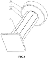
FIG. 1 is an overall view of the structure of the collision energy absorption apparatus according to the present disclosure, -
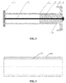
FIG. 2 is a sectional view of the structure of the collision energy absorption apparatus ofFIG. 1 according to the present disclosure, -
FIG. 3 is an axial schematic view of the energy absorption tearing tube of the present disclosure, -
FIG. 4 is a radial schematic view of the energy absorption tearing tube of the present disclosure, -
FIG. 5 is a sectional structural view of another collision energy absorption apparatus according to the present disclosure; - Reference symbols in the drawings: 1 - energy absorption tearing tube; 2 - connector; 3 - base; 4 - collision fender; 5 - outer guide; 11 - kerf; 111 - inner kerf; 112 - outer kerf; 12 - tearing opening; 31 - semicircle structure; 32 - inner bore in the base.
-
FIGS. 1-4 show a collision energy absorption apparatus for a rail vehicle provided by the present disclosure, including a connector 2, abase 3, and an energyabsorption tearing tube 1 radially disposed on the outside of the outer side of the connector. The connector 2 is a flexible connector such as an iron wire. The inner and outer walls of the energy absorption tearing tube are provided with eight pairs of kerfs which have radial positions corresponding to one another. Each pair of kerfs comprises an inner kerf and an outer kerf. Each kerf is a non-closed linear kerf. The width of each kerf is between 0.1 and 0.25 mm and the depth of each kerf is 1/5 of the wall thickness of the energy absorption round tube, and thus the sum of the depths of each pair of kerfs is 2/5 of the wall thickness of the energy absorption tearing tube. One end of each of the connector and the energy absorption tearing tube is fixedly connected to a collision fender in a length direction, and the other end is connected to the base which includes an inner bore in the base. The connector passes through the inner bore in the base. The base includes semicircle structures with a semi-circular cross-section, such that torn strips of the collision absorption tearing tube formed after the collision can curl in a predetermined direction under the restriction of these structures, thereby resulting in a further increased energy consumption of the system and a reduced space occupied by the energy absorption apparatus. In the drawings, a diameter of the energy absorption tearing tube is 150 mm and a diameter of the semicircle structure is 125 mm. An end of the energy absorption tearing tube closed to the base is provided with eight tearing openings passing through the energy absorption tearing tube in a wall thickness direction. The respective one of the tearing openings are in axially communication with each pair of kerfs, and the tearing openings and the kerfs together form a structure crossing through both ends of the energy absorption tearing tube in the axial direction. The wall thickness of the energyabsorption tearing tube 1 in the drawings is 10 mm. - In the present disclosure, the "non-closed linear kerfs" means that the head and the tail of each kerf are not in communication with each other, e.g. each kerf is not an annular closed kerf. The lines of the kerfs may be in a variety of forms such as a straight line, a curved line, or a fold line and the like. When the energy absorption tearing tube is a cylindrical tube, the kerfs for example may be in a form of straight lines parallel to an axis of the energy absorption tearing tube; when the energy absorption tearing tube is a circular truncated cone tube, the kerfs for example may also be in a form of straight lines following the outer wall of the circular truncated cone. Further, when the energy absorption tearing tube is a tube with a curved outer surface, the kerfs further may be configured to be in a form of curved lines. In a specific embodiment, each kerf is a kerf extending in the length direction of the energy
absorption tearing tube 1. In the present disclosure, the kerfs with a certain depth may be formed in the energyabsorption tearing tube 1 by wire cutting, such as wire cut electrical discharge machining. - Since the width of the grooves in the related art is significantly greater than that of the kerfs in the present disclosure, the inventors of the present disclosure found that all of the round pre-torn tubes of the devices in the above related art are expanded at first and then torn. During the expansion, the plastic deformation of the round pre-torn tubes are concentrated at the grooves, rather than being uniformly distributed in a circumferential direction of the round pre-torn tube, so that the effect of energy absorption of such devices is limited after the collision. The energy absorption tearing tube according to the present disclosure is torn directly in accordance with the guide of the kerfs and without the expansion. Because the width of the kerfs in the present disclosure is small, the precision of the width and depth of the kerfs can be high, for instance, a precision up to the order of 0.001 mm. The presence of the kerfs will not affect the structure of the energy absorption tearing tube before the tearing, thus the thickness of the energy absorption tearing tube according to the present disclosure can be configured to be significantly greater than that of the round pre-torn tube in the related art.
- According to the present disclosure, the outer wall and inner wall of the energy absorption tearing tube are provided with kerfs having a small width, such that the energy absorption tearing tube can be accurately axially torn during the tearing. The kerfs do not come into contact with the base during the tearing, such that a more stable tearing can be obtained.
- In the present disclosure, when the connector is a guide tube, the guide tube is connected with the base by shear bolts, the shear bolts plays a role in indirectly reinforcing the connection between the energy
absorption tearing tube 1 and thebase 3 during normal operation of the vehicle. In the event of a collision of the vehicle, the shear bolts are sheared off, and the guide tube slides in the inner bore in the base 32, to guide the energyabsorption tearing tube 1. In a specific embodiment, the collision energy absorption apparatus are collision energy absorption apparatus for a rail vehicle, the collision fenders 4 are disposed on the front and rear ends of the rail vehicle in a length direction of the rail vehicle, and thebases 3 are fixedly connected to the rail vehicle body. - In a specific embodiment of the disclosure, the
base 3 plays a role of elementarily guiding or fully guiding. When thebase 3 only plays a role of elementarily guiding, the length of the part of the energyabsorption tearing tube 1 and thebase 3 for assembly is 2 to 30%, preferably 5 to 20% of the length of the energy absorption tearing tube1. When the assembly between the energyabsorption tearing tube 1 and thebase 3 plays a role of elementarily guiding, the tearing of the energyabsorption tearing tube 1 is more stable under the fine guidance of the guide tube 2 or the outer guide 5. In the present disclosure, the break limit of the shear bolt is much less than the tear limit of the energyabsorption tearing tube 1, thus the shear bolt is broken before the tear of the energyabsorption tearing tube 1. - The above are only the preferable embodiments of the present disclosure and are not intended to limit the present disclosure. It is apparent for those skilled in the art that modifications or variations to the present disclosure are possible. And any modification, equivalent replacement or improvement within the spirit and the principle of the present disclosure shall fall within the scope of protection of the present disclosure.
Claims (9)
- A collision energy absorption apparatus for a rail vehicle, comprising a connector (2), a base (3), and an energy absorption tearing tube (1) radially disposed on the outside of the connector (2), an inner wall and an outer wall of the energy absorption tearing tube (1) being provided with 2 to 20 pairs of kerfs (11), each pair of kerfs (11) comprising an inner kerf (111) and an outer kerf (112) which have radial positions corresponding to one another on the energy absorption tearing tube (1), each kerf being a non-closed linear kerf, a width of the kerfs being between 0.05 and 0.8 mm, and the sum of depths of each pair of kerfs being less than a wall thickness of the energy absorption tearing tube (1); the base (3) comprises semicircle structures (31), such that torn strips of the energy absorption tearing tube (1) formed after the collision can curl in a predetermined direction under the restriction of these structures.
- The collision energy absorption apparatus according to claim 1, wherein a length direction of the kerfs coincides with a length direction of the energy absorption tearing tube (1), and the width of the kerfs is between 0.08 and 0.5 mm.
- The collision energy absorption apparatus according to claim 2, wherein the width of the kerfs is between 0.1 and 0.3 mm, and the pairs of kerfs are uniformly distributed in a circumferential direction of the energy absorption tearing tube (1).
- The collision energy absorption apparatus according to any one of claims 1 to 3, wherein one end of each of the connector (2) and the energy absorption tearing tube (1) is fixedly connected to a collision fender (4) in a length direction, and the other end of each of the connector and the energy absorption tearing tube is connected to the base (3), the base (3) comprises an inner bore in the base (32), and the connector (2) passes through the inner bore in the base.
- The collision energy absorption apparatus according to any one of claims 1 to 3, wherein a diameter of the energy absorption tearing tube (1) is between 50 and 400 mm, and a diameter of the semicircle structures (31) is between 30 and 350 mm, wherein the diameter of the semicircle structures (31) is 20 to 50 mm less than the diameter of the energy absorption tearing tube (1).
- The collision energy absorption apparatus according to any one of claims 1 to 3, wherein an end of the energy absorption tearing tube (1) closed to the base (3) is provided with tearing openings (12), the tearing openings (12) extend through the wall thickness of the energy absorption tearing tube (1), the number of the tearing openings (12) is the same as the number of the pairs of the kerfs (11), and the tearing openings are in axially communication with the kerfs.
- The collision energy absorption apparatus according to claim 6, wherein the tearing openings (12) and the kerfs (11) together form a structure crossing through both ends of the energy absorption tearing tube (1) in an axial direction of the energy absorption tearing tube.
- The collision energy absorption apparatus according to any one of claims 1 to 3, wherein the wall thickness of the energy absorption tearing tube (1) is between 6 and 20 mm.
- The collision energy absorption apparatus according to any one of claims 1 to 3, wherein a depth of each of the inner kerfs (111) and the outer kerfs (112) is between 1/10 and 2/5 of the wall thickness of the energy absorption tearing tube (1).
Applications Claiming Priority (2)
| Application Number | Priority Date | Filing Date | Title |
|---|---|---|---|
| CN201610115228.4A CN105644579B (en) | 2016-03-01 | 2016-03-01 | A kind of collision energy-absorbing device used for rail vehicle |
| PCT/CN2016/101078 WO2017148145A1 (en) | 2016-03-01 | 2016-09-30 | Collision energy absorption apparatus for rail vehicles |
Publications (3)
| Publication Number | Publication Date |
|---|---|
| EP3424794A1 true EP3424794A1 (en) | 2019-01-09 |
| EP3424794A4 EP3424794A4 (en) | 2019-10-30 |
| EP3424794B1 EP3424794B1 (en) | 2021-11-03 |
Family
ID=56492958
Family Applications (1)
| Application Number | Title | Priority Date | Filing Date |
|---|---|---|---|
| EP16892327.4A Active EP3424794B1 (en) | 2016-03-01 | 2016-09-30 | Collision energy absorption apparatus for rail vehicles |
Country Status (4)
| Country | Link |
|---|---|
| US (1) | US10556603B2 (en) |
| EP (1) | EP3424794B1 (en) |
| CN (1) | CN105644579B (en) |
| WO (1) | WO2017148145A1 (en) |
Families Citing this family (14)
| Publication number | Priority date | Publication date | Assignee | Title |
|---|---|---|---|---|
| CN105644579B (en) | 2016-03-01 | 2018-08-28 | 中南大学 | A kind of collision energy-absorbing device used for rail vehicle |
| CN106240595B (en) * | 2016-09-28 | 2018-02-23 | 中南大学 | A kind of collision energy-absorbing device used for rail vehicle |
| CN107512281B (en) | 2017-07-11 | 2019-03-22 | 中车青岛四方机车车辆股份有限公司 | Energy-absorbing anti-climbing device and train vehicle having the same |
| CN107288075A (en) * | 2017-07-14 | 2017-10-24 | 北京中交华安科技有限公司 | A kind of tubular structure bumper |
| US12012130B2 (en) | 2018-09-22 | 2024-06-18 | Central South University | Reusable collision energy absorption device for rail vehicle |
| CN112389487B (en) * | 2019-08-14 | 2022-05-17 | 中车唐山机车车辆有限公司 | Energy absorption device and railway vehicle |
| CN111267894A (en) * | 2020-03-16 | 2020-06-12 | 哈尔滨工业大学 | Combined energy absorber |
| CN113335331A (en) * | 2021-06-25 | 2021-09-03 | 中车唐山机车车辆有限公司 | Energy absorption device and rail vehicle |
| CN113602358B (en) * | 2021-08-18 | 2023-03-10 | 东风柳州汽车有限公司 | Auxiliary frame and vehicle |
| CN113619633B (en) * | 2021-09-07 | 2023-01-20 | 中车株洲电力机车有限公司 | Metal energy absorption device |
| PL440859A1 (en) * | 2022-04-06 | 2023-10-09 | Axtone Spółka Akcyjna | Impact energy absorbing device for a vehicle |
| CN114802334B (en) * | 2022-05-31 | 2023-08-01 | 国家高速列车青岛技术创新中心 | An anti-climbing energy-absorbing device for rail vehicles |
| CN117588514A (en) * | 2023-12-01 | 2024-02-23 | 西安交通大学 | A metal foam-filled flipping energy-absorbing device |
| CN119084508B (en) * | 2024-10-11 | 2026-03-13 | 哈尔滨工业大学 | A novel thin-walled energy absorber based on multiple biomimetic techniques |
Family Cites Families (27)
| Publication number | Priority date | Publication date | Assignee | Title |
|---|---|---|---|---|
| US2961204A (en) * | 1958-01-23 | 1960-11-22 | John F Rayfield | Deceleration device |
| US3143321A (en) * | 1962-07-12 | 1964-08-04 | John R Mcgehee | Frangible tube energy dissipation |
| US3236333A (en) * | 1963-06-17 | 1966-02-22 | Lockheed Aircraft Corp | Energy absorber |
| US3298465A (en) * | 1964-10-22 | 1967-01-17 | Aai Corp | Energy absorbing arrangement |
| US3635314A (en) * | 1966-06-17 | 1972-01-18 | Ara Inc | Linear-type energy absorber having circular elements between cylinders |
| US3608677A (en) * | 1968-10-03 | 1971-09-28 | North American Rockwell | Fragmenting tube energy absorber |
| DE1913189A1 (en) * | 1969-03-15 | 1970-09-24 | Garthe Kg Wolff | Railway buffer |
| FR2528928A1 (en) * | 1982-06-21 | 1983-12-23 | Picand Roland | Collapsible shock absorber for continuous tube cutter - has continuous cutting action and deflector to divert separated tube end |
| US5074391A (en) * | 1989-04-11 | 1991-12-24 | Sintram Ltd. | Crushable device for absorbing impact energy |
| DE19623449A1 (en) * | 1996-06-12 | 1998-01-02 | Daimler Benz Ag | Tube for motor vehicles used in absorption of impact energy in event of collision |
| DE19627061C2 (en) * | 1996-07-05 | 1998-01-29 | Audi Ag | Deformation element |
| US6308809B1 (en) * | 1999-05-07 | 2001-10-30 | Safety By Design Company | Crash attenuation system |
| DE10140503A1 (en) * | 2001-08-17 | 2003-03-13 | Audi Ag | Deformable tube system for absorbing collision impact forces in vehicle, has tubes joined together via deformation part |
| CN2618820Y (en) * | 2003-04-28 | 2004-06-02 | 管红钧 | Cutting type energy-absorbing object collision protector |
| CN101289089A (en) * | 2007-04-18 | 2008-10-22 | 上海磁浮交通工程技术研究中心 | Rail vehicle anti-collision safety device |
| KR101063942B1 (en) * | 2009-05-21 | 2011-09-14 | 한국철도기술연구원 | Shock absorber |
| CN102398558A (en) * | 2010-09-08 | 2012-04-04 | 李书营 | Collision buffering energy absorption device |
| US8584819B2 (en) * | 2011-02-04 | 2013-11-19 | David S. Bettinger | Re-stabilized impact strut |
| CN102180182A (en) * | 2011-03-30 | 2011-09-14 | 中南大学 | Coupler buffer device with cutting type energy-absorbing bumper |
| CN103507823B (en) * | 2012-06-25 | 2016-02-24 | 南车戚墅堰机车车辆工艺研究所有限公司 | Traction buffer device |
| CN103148144B (en) * | 2013-03-14 | 2015-04-08 | 湖南大学 | Energy absorption device |
| CN103133585B (en) * | 2013-03-14 | 2015-04-08 | 湖南大学 | Method of manufacturing energy absorption device |
| CN104088947B (en) * | 2014-06-06 | 2017-07-07 | 中国核电工程有限公司 | A kind of energy absorbing device of utilization material limits characteristic and preparation method thereof |
| CN104494629B (en) * | 2014-11-19 | 2017-02-22 | 西南交通大学 | Compression type multistep energy absorption device |
| CN105292164B (en) | 2015-10-16 | 2017-11-14 | 中南大学 | Telescopic rail energy-absorbing device for vehicle collision |
| CN205396114U (en) * | 2016-03-01 | 2016-07-27 | 中南大学 | Rail vehicle is with collision energy -absorbing device |
| CN105644579B (en) * | 2016-03-01 | 2018-08-28 | 中南大学 | A kind of collision energy-absorbing device used for rail vehicle |
-
2016
- 2016-03-01 CN CN201610115228.4A patent/CN105644579B/en active Active
- 2016-09-30 US US16/081,066 patent/US10556603B2/en active Active
- 2016-09-30 WO PCT/CN2016/101078 patent/WO2017148145A1/en not_active Ceased
- 2016-09-30 EP EP16892327.4A patent/EP3424794B1/en active Active
Also Published As
| Publication number | Publication date |
|---|---|
| US10556603B2 (en) | 2020-02-11 |
| CN105644579B (en) | 2018-08-28 |
| EP3424794B1 (en) | 2021-11-03 |
| US20190092355A1 (en) | 2019-03-28 |
| WO2017148145A1 (en) | 2017-09-08 |
| EP3424794A4 (en) | 2019-10-30 |
| CN105644579A (en) | 2016-06-08 |
Similar Documents
| Publication | Publication Date | Title |
|---|---|---|
| US10556603B2 (en) | Collision energy absorption apparatus for rail vehicles | |
| EP3611071B1 (en) | Energy-absorbing anti-creeper and train vehicle with energy-absorbing anti-creeper | |
| EP2640620B1 (en) | Coupler assembly for coupling railway wagons | |
| CN103148144B (en) | Energy absorption device | |
| US20180202505A1 (en) | Shock absorber based on the cutting, inward-folding and crushing of composite tube | |
| EP3630576B1 (en) | A device dissipating energy of rail car collisions | |
| CN103818402A (en) | Energy absorbing anti-creep device for track traffic vehicles | |
| CA2235793A1 (en) | Energy-absorbing device | |
| WO2009072843A2 (en) | Tube-buffer for railway vehicles | |
| WO2015015747A1 (en) | Collision-energy absorption device for railway vehicle, and railway vehicle | |
| CN103863351A (en) | Diameter expanding and cutting composite type energy dissipation device and vehicle | |
| CN202481129U (en) | Energy-absorbing mechanism with improved structure for automobile column | |
| CN110979384B (en) | Crushing pipe bending-resistant device for motor train unit | |
| CN204750190U (en) | Backstop roof beam of single track motor car and anti -creep energy -absorbing device thereof | |
| EP3357785B1 (en) | Energy absorption device and rail vehicle having same | |
| CN104827997A (en) | Crash box for vehicle | |
| RU174223U1 (en) | Energy absorbing device for rolling stock protection | |
| CN203766810U (en) | Energy absorbing anti-climbing device for rail transit vehicle | |
| CN205396114U (en) | Rail vehicle is with collision energy -absorbing device | |
| CN205113353U (en) | Vehicle anticreeper | |
| CN205652087U (en) | A bumper system and vehicle for vehicle | |
| CN105438101A (en) | Energy absorption structure of hazardous chemicals transport vehicle | |
| CN204309726U (en) | Automobile collapse energy-absorption box | |
| CN212585985U (en) | Polyurethane energy-absorbing pipe | |
| KR102954401B1 (en) | Cutting-Type Shock Absorber having Different Circumferences |
Legal Events
| Date | Code | Title | Description |
|---|---|---|---|
| STAA | Information on the status of an ep patent application or granted ep patent |
Free format text: STATUS: THE INTERNATIONAL PUBLICATION HAS BEEN MADE |
|
| PUAI | Public reference made under article 153(3) epc to a published international application that has entered the european phase |
Free format text: ORIGINAL CODE: 0009012 |
|
| STAA | Information on the status of an ep patent application or granted ep patent |
Free format text: STATUS: REQUEST FOR EXAMINATION WAS MADE |
|
| 17P | Request for examination filed |
Effective date: 20180924 |
|
| AK | Designated contracting states |
Kind code of ref document: A1 Designated state(s): AL AT BE BG CH CY CZ DE DK EE ES FI FR GB GR HR HU IE IS IT LI LT LU LV MC MK MT NL NO PL PT RO RS SE SI SK SM TR |
|
| AX | Request for extension of the european patent |
Extension state: BA ME |
|
| DAV | Request for validation of the european patent (deleted) | ||
| DAX | Request for extension of the european patent (deleted) | ||
| A4 | Supplementary search report drawn up and despatched |
Effective date: 20190926 |
|
| RIC1 | Information provided on ipc code assigned before grant |
Ipc: B61G 11/18 20060101ALI20190920BHEP Ipc: B61F 19/04 20060101AFI20190920BHEP |
|
| GRAP | Despatch of communication of intention to grant a patent |
Free format text: ORIGINAL CODE: EPIDOSNIGR1 |
|
| STAA | Information on the status of an ep patent application or granted ep patent |
Free format text: STATUS: GRANT OF PATENT IS INTENDED |
|
| INTG | Intention to grant announced |
Effective date: 20210428 |
|
| GRAS | Grant fee paid |
Free format text: ORIGINAL CODE: EPIDOSNIGR3 |
|
| GRAA | (expected) grant |
Free format text: ORIGINAL CODE: 0009210 |
|
| STAA | Information on the status of an ep patent application or granted ep patent |
Free format text: STATUS: THE PATENT HAS BEEN GRANTED |
|
| AK | Designated contracting states |
Kind code of ref document: B1 Designated state(s): AL AT BE BG CH CY CZ DE DK EE ES FI FR GB GR HR HU IE IS IT LI LT LU LV MC MK MT NL NO PL PT RO RS SE SI SK SM TR |
|
| REG | Reference to a national code |
Ref country code: GB Ref legal event code: FG4D |
|
| REG | Reference to a national code |
Ref country code: AT Ref legal event code: REF Ref document number: 1443713 Country of ref document: AT Kind code of ref document: T Effective date: 20211115 Ref country code: CH Ref legal event code: EP |
|
| REG | Reference to a national code |
Ref country code: IE Ref legal event code: FG4D |
|
| REG | Reference to a national code |
Ref country code: DE Ref legal event code: R096 Ref document number: 602016065876 Country of ref document: DE |
|
| REG | Reference to a national code |
Ref country code: LT Ref legal event code: MG9D |
|
| REG | Reference to a national code |
Ref country code: NL Ref legal event code: MP Effective date: 20211103 |
|
| REG | Reference to a national code |
Ref country code: AT Ref legal event code: MK05 Ref document number: 1443713 Country of ref document: AT Kind code of ref document: T Effective date: 20211103 |
|
| PG25 | Lapsed in a contracting state [announced via postgrant information from national office to epo] |
Ref country code: RS Free format text: LAPSE BECAUSE OF FAILURE TO SUBMIT A TRANSLATION OF THE DESCRIPTION OR TO PAY THE FEE WITHIN THE PRESCRIBED TIME-LIMIT Effective date: 20211103 Ref country code: LT Free format text: LAPSE BECAUSE OF FAILURE TO SUBMIT A TRANSLATION OF THE DESCRIPTION OR TO PAY THE FEE WITHIN THE PRESCRIBED TIME-LIMIT Effective date: 20211103 Ref country code: FI Free format text: LAPSE BECAUSE OF FAILURE TO SUBMIT A TRANSLATION OF THE DESCRIPTION OR TO PAY THE FEE WITHIN THE PRESCRIBED TIME-LIMIT Effective date: 20211103 Ref country code: BG Free format text: LAPSE BECAUSE OF FAILURE TO SUBMIT A TRANSLATION OF THE DESCRIPTION OR TO PAY THE FEE WITHIN THE PRESCRIBED TIME-LIMIT Effective date: 20220203 Ref country code: AT Free format text: LAPSE BECAUSE OF FAILURE TO SUBMIT A TRANSLATION OF THE DESCRIPTION OR TO PAY THE FEE WITHIN THE PRESCRIBED TIME-LIMIT Effective date: 20211103 |
|
| PG25 | Lapsed in a contracting state [announced via postgrant information from national office to epo] |
Ref country code: IS Free format text: LAPSE BECAUSE OF FAILURE TO SUBMIT A TRANSLATION OF THE DESCRIPTION OR TO PAY THE FEE WITHIN THE PRESCRIBED TIME-LIMIT Effective date: 20220303 Ref country code: SE Free format text: LAPSE BECAUSE OF FAILURE TO SUBMIT A TRANSLATION OF THE DESCRIPTION OR TO PAY THE FEE WITHIN THE PRESCRIBED TIME-LIMIT Effective date: 20211103 Ref country code: PT Free format text: LAPSE BECAUSE OF FAILURE TO SUBMIT A TRANSLATION OF THE DESCRIPTION OR TO PAY THE FEE WITHIN THE PRESCRIBED TIME-LIMIT Effective date: 20220303 Ref country code: PL Free format text: LAPSE BECAUSE OF FAILURE TO SUBMIT A TRANSLATION OF THE DESCRIPTION OR TO PAY THE FEE WITHIN THE PRESCRIBED TIME-LIMIT Effective date: 20211103 Ref country code: NO Free format text: LAPSE BECAUSE OF FAILURE TO SUBMIT A TRANSLATION OF THE DESCRIPTION OR TO PAY THE FEE WITHIN THE PRESCRIBED TIME-LIMIT Effective date: 20220203 Ref country code: NL Free format text: LAPSE BECAUSE OF FAILURE TO SUBMIT A TRANSLATION OF THE DESCRIPTION OR TO PAY THE FEE WITHIN THE PRESCRIBED TIME-LIMIT Effective date: 20211103 Ref country code: LV Free format text: LAPSE BECAUSE OF FAILURE TO SUBMIT A TRANSLATION OF THE DESCRIPTION OR TO PAY THE FEE WITHIN THE PRESCRIBED TIME-LIMIT Effective date: 20211103 Ref country code: HR Free format text: LAPSE BECAUSE OF FAILURE TO SUBMIT A TRANSLATION OF THE DESCRIPTION OR TO PAY THE FEE WITHIN THE PRESCRIBED TIME-LIMIT Effective date: 20211103 Ref country code: GR Free format text: LAPSE BECAUSE OF FAILURE TO SUBMIT A TRANSLATION OF THE DESCRIPTION OR TO PAY THE FEE WITHIN THE PRESCRIBED TIME-LIMIT Effective date: 20220204 Ref country code: ES Free format text: LAPSE BECAUSE OF FAILURE TO SUBMIT A TRANSLATION OF THE DESCRIPTION OR TO PAY THE FEE WITHIN THE PRESCRIBED TIME-LIMIT Effective date: 20211103 |
|
| PG25 | Lapsed in a contracting state [announced via postgrant information from national office to epo] |
Ref country code: SM Free format text: LAPSE BECAUSE OF FAILURE TO SUBMIT A TRANSLATION OF THE DESCRIPTION OR TO PAY THE FEE WITHIN THE PRESCRIBED TIME-LIMIT Effective date: 20211103 Ref country code: SK Free format text: LAPSE BECAUSE OF FAILURE TO SUBMIT A TRANSLATION OF THE DESCRIPTION OR TO PAY THE FEE WITHIN THE PRESCRIBED TIME-LIMIT Effective date: 20211103 Ref country code: RO Free format text: LAPSE BECAUSE OF FAILURE TO SUBMIT A TRANSLATION OF THE DESCRIPTION OR TO PAY THE FEE WITHIN THE PRESCRIBED TIME-LIMIT Effective date: 20211103 Ref country code: EE Free format text: LAPSE BECAUSE OF FAILURE TO SUBMIT A TRANSLATION OF THE DESCRIPTION OR TO PAY THE FEE WITHIN THE PRESCRIBED TIME-LIMIT Effective date: 20211103 Ref country code: DK Free format text: LAPSE BECAUSE OF FAILURE TO SUBMIT A TRANSLATION OF THE DESCRIPTION OR TO PAY THE FEE WITHIN THE PRESCRIBED TIME-LIMIT Effective date: 20211103 Ref country code: CZ Free format text: LAPSE BECAUSE OF FAILURE TO SUBMIT A TRANSLATION OF THE DESCRIPTION OR TO PAY THE FEE WITHIN THE PRESCRIBED TIME-LIMIT Effective date: 20211103 |
|
| REG | Reference to a national code |
Ref country code: DE Ref legal event code: R097 Ref document number: 602016065876 Country of ref document: DE |
|
| PLBE | No opposition filed within time limit |
Free format text: ORIGINAL CODE: 0009261 |
|
| STAA | Information on the status of an ep patent application or granted ep patent |
Free format text: STATUS: NO OPPOSITION FILED WITHIN TIME LIMIT |
|
| 26N | No opposition filed |
Effective date: 20220804 |
|
| PG25 | Lapsed in a contracting state [announced via postgrant information from national office to epo] |
Ref country code: AL Free format text: LAPSE BECAUSE OF FAILURE TO SUBMIT A TRANSLATION OF THE DESCRIPTION OR TO PAY THE FEE WITHIN THE PRESCRIBED TIME-LIMIT Effective date: 20211103 |
|
| PG25 | Lapsed in a contracting state [announced via postgrant information from national office to epo] |
Ref country code: SI Free format text: LAPSE BECAUSE OF FAILURE TO SUBMIT A TRANSLATION OF THE DESCRIPTION OR TO PAY THE FEE WITHIN THE PRESCRIBED TIME-LIMIT Effective date: 20211103 |
|
| REG | Reference to a national code |
Ref country code: DE Ref legal event code: R119 Ref document number: 602016065876 Country of ref document: DE |
|
| PG25 | Lapsed in a contracting state [announced via postgrant information from national office to epo] |
Ref country code: MC Free format text: LAPSE BECAUSE OF FAILURE TO SUBMIT A TRANSLATION OF THE DESCRIPTION OR TO PAY THE FEE WITHIN THE PRESCRIBED TIME-LIMIT Effective date: 20211103 |
|
| REG | Reference to a national code |
Ref country code: CH Ref legal event code: PL |
|
| REG | Reference to a national code |
Ref country code: BE Ref legal event code: MM Effective date: 20220930 |
|
| PG25 | Lapsed in a contracting state [announced via postgrant information from national office to epo] |
Ref country code: IT Free format text: LAPSE BECAUSE OF FAILURE TO SUBMIT A TRANSLATION OF THE DESCRIPTION OR TO PAY THE FEE WITHIN THE PRESCRIBED TIME-LIMIT Effective date: 20211103 |
|
| PG25 | Lapsed in a contracting state [announced via postgrant information from national office to epo] |
Ref country code: LU Free format text: LAPSE BECAUSE OF NON-PAYMENT OF DUE FEES Effective date: 20220930 |
|
| PG25 | Lapsed in a contracting state [announced via postgrant information from national office to epo] |
Ref country code: LI Free format text: LAPSE BECAUSE OF NON-PAYMENT OF DUE FEES Effective date: 20220930 Ref country code: IE Free format text: LAPSE BECAUSE OF NON-PAYMENT OF DUE FEES Effective date: 20220930 Ref country code: FR Free format text: LAPSE BECAUSE OF NON-PAYMENT OF DUE FEES Effective date: 20220930 Ref country code: DE Free format text: LAPSE BECAUSE OF NON-PAYMENT OF DUE FEES Effective date: 20230401 Ref country code: CH Free format text: LAPSE BECAUSE OF NON-PAYMENT OF DUE FEES Effective date: 20220930 |
|
| PG25 | Lapsed in a contracting state [announced via postgrant information from national office to epo] |
Ref country code: BE Free format text: LAPSE BECAUSE OF NON-PAYMENT OF DUE FEES Effective date: 20220930 |
|
| PG25 | Lapsed in a contracting state [announced via postgrant information from national office to epo] |
Ref country code: HU Free format text: LAPSE BECAUSE OF FAILURE TO SUBMIT A TRANSLATION OF THE DESCRIPTION OR TO PAY THE FEE WITHIN THE PRESCRIBED TIME-LIMIT; INVALID AB INITIO Effective date: 20160930 |
|
| PG25 | Lapsed in a contracting state [announced via postgrant information from national office to epo] |
Ref country code: CY Free format text: LAPSE BECAUSE OF FAILURE TO SUBMIT A TRANSLATION OF THE DESCRIPTION OR TO PAY THE FEE WITHIN THE PRESCRIBED TIME-LIMIT Effective date: 20211103 |
|
| PG25 | Lapsed in a contracting state [announced via postgrant information from national office to epo] |
Ref country code: MK Free format text: LAPSE BECAUSE OF FAILURE TO SUBMIT A TRANSLATION OF THE DESCRIPTION OR TO PAY THE FEE WITHIN THE PRESCRIBED TIME-LIMIT Effective date: 20211103 |
|
| PG25 | Lapsed in a contracting state [announced via postgrant information from national office to epo] |
Ref country code: MT Free format text: LAPSE BECAUSE OF FAILURE TO SUBMIT A TRANSLATION OF THE DESCRIPTION OR TO PAY THE FEE WITHIN THE PRESCRIBED TIME-LIMIT Effective date: 20211103 |
|
| PGFP | Annual fee paid to national office [announced via postgrant information from national office to epo] |
Ref country code: GB Payment date: 20250922 Year of fee payment: 10 |
|
| PG25 | Lapsed in a contracting state [announced via postgrant information from national office to epo] |
Ref country code: TR Free format text: LAPSE BECAUSE OF FAILURE TO SUBMIT A TRANSLATION OF THE DESCRIPTION OR TO PAY THE FEE WITHIN THE PRESCRIBED TIME-LIMIT Effective date: 20211103 |