EP3424788B1 - Agricultural work vehicle - Google Patents
Agricultural work vehicle Download PDFInfo
- Publication number
- EP3424788B1 EP3424788B1 EP18163100.3A EP18163100A EP3424788B1 EP 3424788 B1 EP3424788 B1 EP 3424788B1 EP 18163100 A EP18163100 A EP 18163100A EP 3424788 B1 EP3424788 B1 EP 3424788B1
- Authority
- EP
- European Patent Office
- Prior art keywords
- implement
- working vehicle
- control device
- braking
- attachment
- Prior art date
- Legal status (The legal status is an assumption and is not a legal conclusion. Google has not performed a legal analysis and makes no representation as to the accuracy of the status listed.)
- Active
Links
- 239000004459 forage Substances 0.000 claims description 21
- 230000005540 biological transmission Effects 0.000 claims description 16
- 230000002706 hydrostatic effect Effects 0.000 claims description 11
- 238000000034 method Methods 0.000 claims description 9
- 230000001419 dependent effect Effects 0.000 claims description 8
- 238000006073 displacement reaction Methods 0.000 claims description 5
- 230000006870 function Effects 0.000 description 13
- 238000000418 atomic force spectrum Methods 0.000 description 10
- 230000000694 effects Effects 0.000 description 8
- 238000003306 harvesting Methods 0.000 description 5
- 230000003068 static effect Effects 0.000 description 5
- 238000011161 development Methods 0.000 description 3
- 230000018109 developmental process Effects 0.000 description 3
- 239000000446 fuel Substances 0.000 description 2
- 230000005484 gravity Effects 0.000 description 2
- 230000001133 acceleration Effects 0.000 description 1
- 230000003750 conditioning effect Effects 0.000 description 1
- 230000001276 controlling effect Effects 0.000 description 1
- 238000001514 detection method Methods 0.000 description 1
- 230000001105 regulatory effect Effects 0.000 description 1
- 230000011664 signaling Effects 0.000 description 1
- 125000006850 spacer group Chemical group 0.000 description 1
Images
Classifications
-
- B—PERFORMING OPERATIONS; TRANSPORTING
- B60—VEHICLES IN GENERAL
- B60T—VEHICLE BRAKE CONTROL SYSTEMS OR PARTS THEREOF; BRAKE CONTROL SYSTEMS OR PARTS THEREOF, IN GENERAL; ARRANGEMENT OF BRAKING ELEMENTS ON VEHICLES IN GENERAL; PORTABLE DEVICES FOR PREVENTING UNWANTED MOVEMENT OF VEHICLES; VEHICLE MODIFICATIONS TO FACILITATE COOLING OF BRAKES
- B60T8/00—Arrangements for adjusting wheel-braking force to meet varying vehicular or ground-surface conditions, e.g. limiting or varying distribution of braking force
- B60T8/17—Using electrical or electronic regulation means to control braking
- B60T8/176—Brake regulation specially adapted to prevent excessive wheel slip during vehicle deceleration, e.g. ABS
- B60T8/1766—Proportioning of brake forces according to vehicle axle loads, e.g. front to rear of vehicle
-
- B—PERFORMING OPERATIONS; TRANSPORTING
- B60—VEHICLES IN GENERAL
- B60T—VEHICLE BRAKE CONTROL SYSTEMS OR PARTS THEREOF; BRAKE CONTROL SYSTEMS OR PARTS THEREOF, IN GENERAL; ARRANGEMENT OF BRAKING ELEMENTS ON VEHICLES IN GENERAL; PORTABLE DEVICES FOR PREVENTING UNWANTED MOVEMENT OF VEHICLES; VEHICLE MODIFICATIONS TO FACILITATE COOLING OF BRAKES
- B60T8/00—Arrangements for adjusting wheel-braking force to meet varying vehicular or ground-surface conditions, e.g. limiting or varying distribution of braking force
- B60T8/17—Using electrical or electronic regulation means to control braking
- B60T8/1701—Braking or traction control means specially adapted for particular types of vehicles
-
- B—PERFORMING OPERATIONS; TRANSPORTING
- B60—VEHICLES IN GENERAL
- B60T—VEHICLE BRAKE CONTROL SYSTEMS OR PARTS THEREOF; BRAKE CONTROL SYSTEMS OR PARTS THEREOF, IN GENERAL; ARRANGEMENT OF BRAKING ELEMENTS ON VEHICLES IN GENERAL; PORTABLE DEVICES FOR PREVENTING UNWANTED MOVEMENT OF VEHICLES; VEHICLE MODIFICATIONS TO FACILITATE COOLING OF BRAKES
- B60T8/00—Arrangements for adjusting wheel-braking force to meet varying vehicular or ground-surface conditions, e.g. limiting or varying distribution of braking force
- B60T8/26—Arrangements for adjusting wheel-braking force to meet varying vehicular or ground-surface conditions, e.g. limiting or varying distribution of braking force characterised by producing differential braking between front and rear wheels
- B60T8/30—Arrangements for adjusting wheel-braking force to meet varying vehicular or ground-surface conditions, e.g. limiting or varying distribution of braking force characterised by producing differential braking between front and rear wheels responsive to load
Definitions
- the present invention relates to an agricultural work vehicle with a device for accommodating an attachment and a device for accommodating counterweights, as well as a chassis comprising at least two axles, a front axle and a rear axle, on which torque transmission means are arranged, with a brake system that can be controlled by a control device, which comprises at least one braking device acting on at least one of the axles or the torque transmission means arranged thereon. Furthermore, the invention relates to a method for operating a rural work vehicle according to the preamble of claim 11.
- the EP 2 009 329 B1 describes a harvesting machine with a control device for regulating the hydraulic drive unit of a travel drive as a function of static and dynamic machine parameters.
- a static machine parameter is formed by the respective front attachment arranged on the harvesting machine, which enters the control device with specification of the type designation and equipment.
- the interchangeable attachments determine the wheel or axle load on the drive wheels and thus influence the traction and slip behavior of the drive wheels.
- the static and dynamic machine parameters are used to adjust the displacement of the hydraulic drive units to optimize traction and prevent slippage.
- the agricultural working vehicle designed as a tractor has front and rear device interfaces for attaching different working devices and/or ballasts counterweights.
- the tractor also has a chassis with a front axle and a rear axle, on which wheels are arranged as torque transmission means.
- a braking system is provided for braking the tractor, which has braking devices acting on the wheels.
- the braking system is controlled by a control device.
- the braking system is controlled as a function of the static and dynamic chassis forces acting on the axles in the vertical direction, which are detected by a sensor arrangement.
- the control device calculates a distribution of the occurring axle forces in order to derive from the calculated distribution for the braking devices a specification with regard to the distribution of the braking forces provided by the braking system.
- the detection of the static and dynamic chassis forces requires the arrangement of wheel and axle sensors in order to distribute the available brake pressure depending on the chassis forces.
- a rural working vehicle is proposed, with a device for accommodating an attachment and a device for accommodating counterweights, as well as one comprising at least two axles Running gear, a front axle and a rear axle, on which torque transmission means are arranged, and with a controllable by a control device brake system, which comprises at least one braking device acting on at least one of the axles or the torque transmission means arranged thereon.
- Torque transmission means are understood to mean tires or crawler tracks, which can each be arranged exclusively or in combination with one another on the axles.
- the control device be set up to, depending on at least one attachment-specific property which can be determined by the control device using information provided about the type of attachment, one of the braking system on the Front axle provided maximum brake pressure and / or adjust a brake pressure curve.
- This has the advantage that the braking system provides the braking power as required, ie adapted to the actual total weight of the working vehicle and the respective attachment mounted on it.
- the invention provides a need-based widening of the brake pressure, which ensures that the work vehicle with the attached implement comes to a standstill within a legally prescribed braking distance.
- the control of the braking system according to the invention by the control device takes place both when driving in fields and when driving on the road when an attachment is connected to the working vehicle.
- Implement type information can be provided in a number of ways.
- a preferred possibility is that when the attachment is connected to the work vehicle, the type of attachment is automatically determined by the control device.
- the provision of information about the type of attachment can also take place based on a manual input by an operator if this cannot be determined automatically, for example. In this way, the same braking distances can be achieved landscape working vehicle with different types of attachments.
- the need-based provision of braking power leads to a reduced locking tendency of the front axle, which is associated with improved controllability and more stable handling of the work vehicle during braking.
- control device can be set up to increase the maximum brake pressure provided as the weight of the attachment increases.
- the negative acceleration per unit of time increases as the weight of the attachment increases.
- the brake system can include a load-dependent brake valve.
- a specific brake pressure can be set by means of the load-dependent brake valve, which can be determined from the weight of the working vehicle and that of the attachment mounted on it. That is, the load-sensing brake valve is adjustable depending on the machine load. In this way, the front axle can be braked to different extents depending on the attached implement, with the resulting braking distance always being within the legally specified braking distances within which the working vehicle must come to a standstill.
- the load-dependent brake valve can be designed as a continuous valve, in particular as a proportional valve.
- control device is set up to determine the counterweight to be accommodated as a function of the attachment type and the at least one attachment-specific property.
- An arrangement of counterweights adapted to the respective attachment results in less ballast on the working vehicle.
- the counterweight that is specific to the respective type of attachment and is to be arranged on the work vehicle can be brought to the knowledge of an operator by the control device so that this can be taken into account when equipping the work vehicle. This leads to a reduction in the overall weight of the working vehicle, which is associated with lower fuel consumption.
- the at least one braking device can expediently be designed as a friction brake, with at least one of the axles being assigned a friction brake to at least each of the torque transmission means. Friction brakes can thus be assigned to each of the torque transmission means, both the front axle and the at least one further rear axle.
- the friction brakes can be disk brakes, disc brakes or drum brakes.
- At least one of the axles of the utility vehicle can be assigned a hydrostatic travel drive, which is set up to partially or completely generate a braking effect.
- a braking effect can be generated entirely or partially by the pressure difference in the hydrostatic circuit of the drive. In this way, a purely hydrostatic braking device could be implemented, which would do without a friction brake as the service brake.
- the control device can preferably be set up to control a hydraulic motor or a hydraulic pump of the hydrostatic travel drive in order to generate at least an additional braking force as a function of at least one attachment-specific property.
- the braking effect of the friction brakes on the front axle and/or rear axle can be supported as a function of the load.
- the braking force can be generated solely by the at least one hydraulic motor or the at least one hydraulic pump, with the actuation taking place as a function of at least one attachment-specific property.
- control device can be set up to adjust a maximum brake pressure provided by the brake system on the rear axle and/or on an additional axle assigned to the work vehicle as a function of the at least one attachment-specific property.
- the additional axle can be a third axle of the working vehicle or act an axle arranged on the attachment.
- the additional axle also has braking devices, which can be subjected to a braking pressure by the braking system in a manner according to the invention.
- a further attachment-specific property can be a support arrangement located on the attachment.
- the support arrangement can include support wheels or skids which are integrated into the attachment or are attached to the attachment by means of an attachment device.
- the latter arrangement of the support arrangement by means of the hitch comes into play when the working vehicle is driving on the road. Since the presence of a support arrangement on the attachment serves, among other things, to relieve the axle to which the attachment is arranged adjacent, usually the front axle, this also affects the required braking power.
- the agricultural working vehicle can preferably be designed as a tractor, self-propelled combine harvester or forage harvester.
- the object is also achieved by a method for operating an agricultural working vehicle, in particular a forage harvester.
- the agricultural work vehicle includes a device that picks up an attachment and a device that picks up counterweights, as well as a chassis that has at least two axles, a front axle and a rear axle, on which torque transmission means are arranged, with the at least one axle or the torque transmission means arranged thereon is acted upon by a braking system which is controlled by a control device.
- a maximum brake pressure provided by the brake system at least on the front axle and/or a brake pressure curve is adjusted as a function of at least one attachment-specific property, which is determined by the control device based on information provided about the type of attachment picked up, so that as the mass of the attachment increases the braking effect increases.
- the provision of the recorded attachment type is carried out when connecting the attachment to the work vehicle. This can be done automatically by recognizing the attachment, for example by the transmission of data by the attachment to the control device of the work vehicle, which enables identification of the type of attachment or by reading out a memory provided on the attachment, which stores specific data for the attachment. Of course, this data can also be entered manually by a person operating the work vehicle using an input/output device.
- the weight of the attachment is determined as an attachment-specific property, which, in conjunction with the weight of the work vehicle, is taken as a basis for adjusting the maximum brake pressure provided on the front axle.
- the necessary counterweight to be taken up can be determined and displayed.
- the control device can be in signaling connection with an input/output device which is arranged in a cab of the utility vehicle.
- the maximum brake pressure available on the front axle can be changed in such a way that the braking effect increases.
- At least one load-dependent brake valve can preferably be activated to change the maximum brake pressure provided.
- the displacement of a hydraulic motor and/or a hydraulic pump of a hydraulic travel drive can be changed as a function of the at least one attachment-specific property.
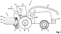
- attachment 1 shows a schematic representation of an agricultural working vehicle with attachment 2 arranged on it.
- the agricultural working vehicle is designed as a forage harvester 1 .
- the attachment 2 is designed to be foldable in order not to exceed the maximum width permitted for road travel. Accordingly, the attachment 2 is unfolded during harvesting.
- the term attachment includes any attachment or attachment that can be attached to an agricultural working vehicle, regardless of whether it can be folded up or not.
- the attachment or attachment 2 includes integrated support wheels 3, which support the attachment 2 relative to the ground. The support force applied by the support wheels 3 can be adjustable by an actuator in each case.
- the forage harvester 1 shown in a side view is driven by front main drive wheels 5 arranged on a front axle 6 and steered by steerable rear wheels 7 arranged on a rear axle 8 .
- the rear wheels 7 can also be driven.
- the front wheels and/or rear wheels of the forage harvester shown can also be designed as belt, caterpillar or chain drives. The following explanations also apply accordingly in this case.
- a feed device 4 is provided in the front area, through which the harvested crop is fed into the interior of the forage harvester 1 .
- the harvested crop arrives from the intake device 4 through processing devices for the harvested crop (not shown), in particular a chopping device, an optional conditioning device and a post-acceleration device, to an ejection device 10 which is arranged behind a driver's cab 9 .
- the ejection device 10 conveys the harvested crop into a trailer which is carried alongside or behind the forage harvester 1 and which is pulled by a tractor, for example.
- Means are provided on the intake device 4, on which the attachment 2 can be hung.
- a main frame of the attachment 2 runs into and out of the image plane and thus transversely, i.e. offset by an angle of about 90°, to the direction of travel F of the vehicle 1.
- the foldable attachment 2 has a middle section 12 and outer sections 12 ', 12
- the outer sections 12′, 12′′ in the transport position of the attachment 2 are indicated with dashed lines.
- the forage harvester 1 includes a control device 13 which is used to control a braking system of the forage harvester 1 .
- the control device 13 is connected to an input/output device 14 in the cabin 9 by a signal and control line 17 .
- a brake pedal 15 is arranged in the cab 9, which is actuated by an operator in order to bring the forage harvester 1 to a standstill.
- the brake pedal 15 is also connected to the control device 13 by a signal and control line 17 .
- counterweights 16 are arranged, which are used for ballasting.
- the counterweights 16 provide a corresponding load on the rear axle 8 in order to at least reduce the lifting tendency of the forage harvester 1 when braking.
- the front axle 6 can be relieved by the ballasting.
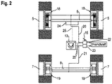
- FIG. 2 is a schematic representation of a chassis of the forage harvester 1. Due to the arrangement of the attachment 2 on the intake device 4, the common center of gravity of the attachment and the harvesting machine is closer to the front axle 6 than to the rear axle 8 of the chassis, so that the proportion of the weight of the Forage harvester 1, which carries the front axle 6, is greater than the part carried by the rear axle 8. In order to evenly distribute the weight of the machine on the surface being driven on, the front wheels 5 are larger than the steerable rear wheels 7. Since the center of gravity of the machine is higher than the axles 6, 8, the proportion of the load carried by the front axle 1 increases weight even if the machine is decelerated while driving.
- Each wheel 5, 7 is provided with a braking device 18, 19 designed as a friction brake, in this case a—preferably wet—disc brake in the case of the front wheels 5 and a drum brake in the case of the rear wheels 4.
- the braking devices 18 and 19 can each also be used as disc brakes be executed.
- the braking devices 18 of the front wheels 5 and the braking devices 19 of the rear wheels 7 belong to two separate brake circuits 20, 21, both of which are externally controlled by the same brake pedal 15, but use two brake pressure valves 22, 23 actuated by the brake pedal 15 for this purpose .
- the brake pressure valves 22, 23 can use different characteristic curves or differ in terms of valve type, so that the relationship between the actuating force exerted on the brake pedal 15 by an operator of the forage harvester 1 and the resulting brake pressure in the brake circuits 20 or 21 is different.
- At least one hydraulic motor 24 (hydraulic motor), which is part of a hydrostatic travel drive of the forage harvester 1, is assigned to the front axle 6 designed as a drive axle.
- the at least one hydraulic motor 24 is hydraulically connected to a hydraulic pump, not shown, whose displacement is variable.
- the hydraulic motor 24 and the hydraulic pump can each have a Be formed provided unit swash plate, ie as an adjustable axial piston motor or adjustable axial piston pump.
- At least the brake pressure valve 22 of the brake circuit 20 of the front axle 6 is designed as a continuous valve.
- the brake pressure valves 22 and 23 and the hydraulic motor 24 are connected to the control device 13 by signal and control lines 25 .
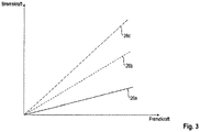
- a graphic which shows an example of the relationship between the external force applied to brake pedal 15 and the braking force generated by the braking system if, according to the invention, the braking system is controlled by control device 13 as a function of an attachment-specific property, in particular the weight of the respective attachment 2 is controlled.
- the graphic shows an example of three curves 26a, 26b and 26c of a braking force, with the braking force curve 26a being an example of an attachment 2 which is characterized by its low weight, the braking force curve in 26b being characteristic of an attachment 2 with a medium weight and the braking force curve 26c, which occurs when attachments 2 are heavy.
- the respective weight of the attachment 2 is determined in particular by its working width.
- the proportional braking force curve depending on the respective combination of work vehicle 1 and attachment 2 is advantageous.
- the adjustment of the braking force depending in particular on the weight of the attachment 2 allows the same braking distances to be achieved with different total machine weights.
- a large number of braking force curves can be stored in the control device 13 so that they can be called up.
- the braking force curves 26a, 26b, 26c can be adjusted.
- the attachment-specific property is determined by the control device 13 using information provided about the attachment type.
- the attachment type can be entered manually by the operator using the input/output device 14 .
- the information provided about the attachment type is used by the control device 13 in order to call up the corresponding attachment-specific properties in a database that can be stored in a memory device of the control device 13 .
- control device 13 can be set up to automatically determine the attachment type of the respective attachment 2 by automatically transferring data between the attachment 2 and the control device 13 when the attachment 2 is connected to the intake device 4 .
- the provided attachment-specific properties are not just limited to the weight of the attached attachment 2.
- the working width of the attachment 2 can be called up or information about whether a support arrangement such as the support wheels 3 is provided on the attachment 2.
- control device 13 is set up to use the attachment-specific properties in order to determine the weight of the counterweights 16 to be attached at the rear.
- This information is transmitted from the control device 13 to the input/output device 14 so that it is available to the operator of the forage harvester 1 so that it can be called up. Accordingly, the operator can adjust the counterweights 16 to the actual weight of the attachment 2, which leads to a reduction in the total weight of the unit made up of the forage harvester 1 and the attachment 2. In addition to fuel savings due to the lower overall machine weight, this leads to a reduction in the required braking power or the maximum braking pressure that has to be provided by the braking system.
- the brake system is actuated by the control device 13 depending on the attachment-specific property only for the brake pressure valve 22 , which is arranged in the brake circuit 20 of the front axle 6 . Corresponding dependencies are stored in the control device 13 for this purpose, so that a predetermined maximum brake pressure is set by the brake pressure valve 22 as a function of the recognized attachment. Accordingly, the front axle 6 is braked to different extents depending on the attachment 2 .
- a development provides that the brake pressure valve 23 of the brake circuit 21 of the rear axle 8 is also controlled by the control device as a function of the attachment-specific property of the attachment 2 .
- the attachment 2 is provided with a spacer arrangement designed as support wheels 3, a braking device can also be arranged on the support wheels 3, which can also be controlled by the control device 13 in the finding according to the manner.
- Another aspect can be the at least load-dependent support of the braking effect of the braking system by the hydraulic motor or motors 24 .
- the braking power of the braking system can be increased, particularly with heavy attachments, by the control device 13 controlling the hydraulic pump feeding the at least one hydraulic motor 24 in such a way that the displacement of the hydraulic pump is at least reduced.
- the hydrostatic travel drive is set up for the partial or complete generation of a braking effect.
- the control device 13 is set up to control the hydraulic motor 24 or a hydraulic pump of the hydrostatic travel drive to generate an additional braking force as a function of the at least one attachment-specific property.
Description
Die vorliegende Erfindung betrifft ein landwirtschaftliches Arbeitsfahrzeug mit einer Vorrichtung zur Aufnahme eines Anbaugerätes und einer Einrichtung zur Aufnahme von Kontergewichten, sowie einem zumindest zwei Achsen umfassenden Fahrwerk, einer Vorderachse und einer Hinterachse, an denen Drehmomentübertragungsmittel angeordnet sind, mit einem durch eine Steuereinrichtung ansteuerbaren Bremssystem, welches wenigstens eine auf zumindest eine der Achsen bzw. die daran angeordneten Drehmomentübertragungsmittel einwirkende Bremseinrichtung umfasst. Weiterhin betrifft die Erfindung ein Verfahren zum Betreiben eines landschaftlichen Arbeitsfahrzeuges gemäß dem Oberbegriff des Anspruchs 11.The present invention relates to an agricultural work vehicle with a device for accommodating an attachment and a device for accommodating counterweights, as well as a chassis comprising at least two axles, a front axle and a rear axle, on which torque transmission means are arranged, with a brake system that can be controlled by a control device, which comprises at least one braking device acting on at least one of the axles or the torque transmission means arranged thereon. Furthermore, the invention relates to a method for operating a rural work vehicle according to the preamble of claim 11.
Die
Aus der
Somit ist es die Aufgabe der Erfindung, ein landwirtschaftliches Arbeitsfahrzeug der eingangs genannten Art sowie ein Verfahren zum Betreiben eines Bremssystems eines landwirtschaftlichen Arbeitsfahrzeuges derart weiter zu entwickeln, dass sich das Arbeitsfahrzeug durch einen effizienteren Betrieb und ein verbessertes Bremsverhalten auszeichnet.It is therefore the object of the invention to further develop an agricultural working vehicle of the type mentioned at the outset and a method for operating a braking system of an agricultural working vehicle in such a way that the working vehicle is characterized by more efficient operation and improved braking behavior.
Diese Aufgabe wird erfindungsgemäß durch ein landwirtschaftliches Arbeitsfahrzeug gemäß dem Anspruch 1 sowie ein Verfahren zum Betreiben eines landwirtschaftlichen Arbeitsfahrzeuges gemäß dem unabhängigen Anspruch 11 gelöst.This object is achieved according to the invention by an agricultural working vehicle according to claim 1 and a method for operating an agricultural working vehicle according to independent claim 11 .
Vorteilhafte Weiterbildungen sind Gegenstand der hiervon abhängigen Unteransprüche.Advantageous developments are the subject matter of the dependent claims.
Gemäß dem Anspruch 1 wird ein landschaftliches Arbeitsfahrzeug vorgeschlagen, mit einer Vorrichtung für eine Aufnahme eines Anbaugerätes und einer Einrichtung für eine Aufnahme von Kontergewichten, sowie einem zumindest zwei Achsen umfassenden Fahrwerk, einer Vorderachse und einer Hinterachse, an denen Drehmomentübertragungsmittel angeordnet sind, und mit einem durch eine Steuereinrichtung ansteuerbaren Bremssystem, welches wenigstens eine auf zumindest eine der Achsen bzw. die daran angeordneten Drehmomentübertragungsmittel einwirkende Bremseinrichtung umfasst. Unter Drehmomentübertragungsmittel werden Reifen oder Raupenfahrwerke verstanden, welche jeweils ausschließlich oder in Kombination miteinander an den Achsen angeordnet sein können. Um einen möglichst effizienten Betrieb des landschaftlichen Arbeitsfahrzeuges zu erreichen, wird erfindungsgemäß vorgeschlagen, dass die Steuereinrichtung dazu eingerichtet ist, in Abhängigkeit von zumindest einer anbaugerätespezifischen Eigenschaft, welche durch die Steuereinrichtung anhand einer bereitgestellten Information über den Anbaugerätetyp ermittelbar ist, einen von dem Bremssystem an der Vorderachse bereitgestellten maximalen Bremsdruck und/oder einen Bremsdruckverlauf anzupassen. Dies hat den Vorteil, dass das Bremssystem die Bremsleistung bedarfsabhängig, das heißt an das tatsächliche Gesamtgewicht von Arbeitsfahrzeug und dem jeweiligen daran angeordneten Anbaugerät angepasst, bereitstellt. Im Unterschied zu dem aus der
Die Bereitstellung von Informationen über den Anbaugerätetyp kann auf unterschiedliche Weise erfolgen. Eine bevorzugte Möglichkeit besteht darin, dass beim Anschließen des Anbaugerätes an das Arbeitsfahrzeug der Anbaugerätetyp durch die Steuereinrichtung automatisch ermittelt wird. Die Bereitstellung von Informationen über den Anbaugerätetyp kann darüber hinaus anhand einer manuellen Eingabe durch eine Bedienperson erfolgen, wenn diese beispielsweise nicht automatisiert ermittelbar sind. Auf diese Weise lassen sich gleiche Bremswege des landschaftlichen Arbeitsfahrzeuges bei unterschiedlichen Anbaugerätetypen darstellen. Die bedarfsabhängige Bereitstellung der Bremsleistung führt zu einer verminderten Blockierneigung der Vorderachse, was mit einer verbesserten Kontrollierbarkeit und einem stabileren Fahrverhalten des Arbeitsfahrzeugs während eines Bremsvorganges einhergeht.Implement type information can be provided in a number of ways. A preferred possibility is that when the attachment is connected to the work vehicle, the type of attachment is automatically determined by the control device. The provision of information about the type of attachment can also take place based on a manual input by an operator if this cannot be determined automatically, for example. In this way, the same braking distances can be achieved landscape working vehicle with different types of attachments. The need-based provision of braking power leads to a reduced locking tendency of the front axle, which is associated with improved controllability and more stable handling of the work vehicle during braking.
Insbesondere kann die Steuereinrichtung dazu eingerichtet sein, den bereitgestellten maximalen Bremsdruck mit zunehmendem Gewicht des Anbaugerätes zu erhöhen. So nimmt mit zunehmendem Gewicht des Anbaugerätes die negative Beschleunigung je Zeiteinheit zu.In particular, the control device can be set up to increase the maximum brake pressure provided as the weight of the attachment increases. The negative acceleration per unit of time increases as the weight of the attachment increases.
Hierzu kann das Bremssystem ein lastabhängiges Bremsventil umfassen. Mittels des lastabhängigen Bremsventils lässt sich ein spezifischer Bremsdruck einstellen, welcher sich aus dem Gewicht des Arbeitsfahrzeugs und dem des daran angeordneten Anbaugerätes bestimmen lässt. Das heißt, das lastabhängige Bremsventil ist in Abhängigkeit von der Maschinenlast einstellbar. Somit kann die Vorderachse in Abhängigkeit von dem aufgenommenen Anbaugerät unterschiedlich stark gebremst werden, wobei sich der jeweils resultierende Bremsweg stets innerhalb der gesetzlich vorgegeben Bremswege befindet, innerhalb der das Arbeitsfahrzeug zum Stillstand kommen muss. Das lastabhängige Bremsventil kann als Stetigventil, insbesondere als Proportionalventil, ausgeführt sein.For this purpose, the brake system can include a load-dependent brake valve. A specific brake pressure can be set by means of the load-dependent brake valve, which can be determined from the weight of the working vehicle and that of the attachment mounted on it. That is, the load-sensing brake valve is adjustable depending on the machine load. In this way, the front axle can be braked to different extents depending on the attached implement, with the resulting braking distance always being within the legally specified braking distances within which the working vehicle must come to a standstill. The load-dependent brake valve can be designed as a continuous valve, in particular as a proportional valve.
Eine vorteilhafte Weiterbildung sieht vor, dass die Steuerungseinrichtung dazu eingerichtet ist, in Abhängigkeit von dem Anbaugerätetyp und der zumindest einen anbaugerätespezifischen Eigenschaft das aufzunehmende Kontergewicht zu bestimmen. Eine an das jeweilige Anbaugerät angepasste Anordnung von Kontergewichten führt zu einer geringeren Ballastierung am Arbeitsfahrzeug. Das für den jeweiligen Anbaugerätetyp spezifische, am Arbeitsfahrzeug anzuordnende Kontergewicht kann einer Bedienperson durch die Steuereinrichtung zur Kenntnis gebracht werden, damit dies beim Ausrüsten des Arbeitsfahrzeugs Berücksichtigung finden kann. Dies führt zu einer Reduzierung des Gesamtgewichts des Arbeitsfahrzeugs, was mit einem geringeren Kraftstoffverbrauch einhergeht. Zweckmäßigerweise kann die wenigstens eine Bremseinrichtung als Reibungsbremse ausgeführt, wobei zumindest jedem der Drehmomentübertragungsmittel zumindest einer der Achsen eine Reibungsbremse zugeordnet ist. So können jedem der Drehmomentübertragungsmittel der sowohl der Vorderachse als auch der zumindest einen weiteren Hinterachse Reibungsbremsen zugeordnet sein. Bei den Reibungsbremsen kann es sich um Lamellenbremsen, Scheibenbremsen oder Trommelbremsen handeln.An advantageous development provides that the control device is set up to determine the counterweight to be accommodated as a function of the attachment type and the at least one attachment-specific property. An arrangement of counterweights adapted to the respective attachment results in less ballast on the working vehicle. The counterweight that is specific to the respective type of attachment and is to be arranged on the work vehicle can be brought to the knowledge of an operator by the control device so that this can be taken into account when equipping the work vehicle. This leads to a reduction in the overall weight of the working vehicle, which is associated with lower fuel consumption. The at least one braking device can expediently be designed as a friction brake, with at least one of the axles being assigned a friction brake to at least each of the torque transmission means. Friction brakes can thus be assigned to each of the torque transmission means, both the front axle and the at least one further rear axle. The friction brakes can be disk brakes, disc brakes or drum brakes.
Weiterhin kann zumindest einer der Achsen des Arbeitsfahrzeugs ein hydrostatischer Fahrantrieb zugeordnet sein, der zur teilweisen oder vollständigen Erzeugung einer Bremswirkung eingerichtet ist. Durch den hydrostatischen Fahrantrieb kann eine Bremswirkung ganz oder teilweise durch die Druckdifferenz im hydrostatischen Kreislauf des Fahrantriebs erzeugt werden. Auf diese Weise ließe sich eine reinhydrostatische Bremseinrichtung realisieren, welche ohne eine Reibungsbremse als Betriebsbremse auskäme.Furthermore, at least one of the axles of the utility vehicle can be assigned a hydrostatic travel drive, which is set up to partially or completely generate a braking effect. With the hydrostatic drive, a braking effect can be generated entirely or partially by the pressure difference in the hydrostatic circuit of the drive. In this way, a purely hydrostatic braking device could be implemented, which would do without a friction brake as the service brake.
Bevorzugt kann die Steuereinrichtung dazu eingerichtet sein, einen Hydraulikmotor oder eine Hydraulikpumpe des hydrostatischen Fahrantriebes zur Erzeugung einer zumindest zusätzlichen Bremskraft in Abhängigkeit von zumindest einer anbaugerätespezifischen Eigenschaft anzusteuern. Hierdurch lässt sich die Bremswirkung der Reibungsbremsen an der Vorderachse und/oder Hinterachse lastabhängig unterstützen. Alternativ kann die Bremskraft von dem wenigstens einen Hydraulikmotor oder der wenigstens einen Hydraulikpumpe allein erzeugt werden, wobei die Ansteuerung in Abhängigkeit von zumindest einer anbaugerätespezifischen Eigenschaft erfolgt.The control device can preferably be set up to control a hydraulic motor or a hydraulic pump of the hydrostatic travel drive in order to generate at least an additional braking force as a function of at least one attachment-specific property. As a result, the braking effect of the friction brakes on the front axle and/or rear axle can be supported as a function of the load. Alternatively, the braking force can be generated solely by the at least one hydraulic motor or the at least one hydraulic pump, with the actuation taking place as a function of at least one attachment-specific property.
Des Weiteren kann die Steuereinrichtung dazu eingerichtet sein, einen an der Hinterachse und/oder einer dem Arbeitsfahrzeug zugeordneten Zusatzachse von dem Bremssystem bereitgestellten maximalen Bremsdruck in Abhängigkeit von der zumindest einen anbaugerätespezifischen Eigenschaft anzupassen. Bei der Zusatzachse kann es sich um eine dritte Achse des Arbeitsfahrzeugs oder um eine an dem Anbaugerät angeordnete Achse handeln. Die Zusatzachse weist ebenfalls Bremseinrichtungen auf, die von dem Bremssystem in erfindungsgemäßer Weise mit einem Bremsdruck beaufschlagbar sind.Furthermore, the control device can be set up to adjust a maximum brake pressure provided by the brake system on the rear axle and/or on an additional axle assigned to the work vehicle as a function of the at least one attachment-specific property. The additional axle can be a third axle of the working vehicle or act an axle arranged on the attachment. The additional axle also has braking devices, which can be subjected to a braking pressure by the braking system in a manner according to the invention.
Insbesondere kann eine weitere anbaugerätespezifische Eigenschaft eine am Anbaugerät befindliche Abstützanordnung sein. Die Abstützanordnung kann Stützräder oder Kufen umfassen, welche in das Anbaugerät integriert sind oder mittels einer Anbauvorrichtung an dem Anbaugerät angebracht werden. Letztere Anordnung der Abstützanordnung mittels der Anbauvorrichtung kommt bei einer Straßenfahrt des Arbeitsfahrzeugs zum Tragen. Da das Vorhandensein einer Abstützanordnung an dem Anbaugerät unter anderem dazu dient, die Achse zu entlasten, zu welcher das Anbaugerät benachbart angeordnet ist, in der Regel die Vorderachse, beeinflusst dies ebenfalls die erforderliche Bremsleistung.In particular, a further attachment-specific property can be a support arrangement located on the attachment. The support arrangement can include support wheels or skids which are integrated into the attachment or are attached to the attachment by means of an attachment device. The latter arrangement of the support arrangement by means of the hitch comes into play when the working vehicle is driving on the road. Since the presence of a support arrangement on the attachment serves, among other things, to relieve the axle to which the attachment is arranged adjacent, usually the front axle, this also affects the required braking power.
Bevorzugt kann das landwirtschaftliche Arbeitsfahrzeug als Traktor, selbstfahrender Mähdrescher oder Feldhäcksler ausgeführt sein.The agricultural working vehicle can preferably be designed as a tractor, self-propelled combine harvester or forage harvester.
Weiterhin wird die Aufgabe durch ein Verfahren zum Betreiben eines landwirtschaftlichen Arbeitsfahrzeugs, insbesondere eines Feldhäcksler, gelöst. Das landwirtschaftliche Arbeitsfahrzeug umfasst eine Vorrichtung, von der ein Anbaugerät aufgenommen wird, und eine Einrichtung, von der Kontergewichte aufgenommen werden, sowie ein zumindest zwei Achsen umfassendes Fahrwerk, einer Vorderachse und einer Hinterachse, an denen Drehmomentübertragungsmittel angeordnet sind, wobei auf die zumindest eine Achse bzw. die daran angeordneten Drehmomentübertragungsmittel durch ein Bremssystem eingewirkt wird, welches durch eine Steuereinrichtung angesteuert wird. Erfindungsgemäß wird in Abhängigkeit von zumindest einer anbaugerätespezifischen Eigenschaft, welche durch die Steuereinrichtung anhand einer bereitgestellten Information über den aufgenommenen Anbaugerätetyp ermittelt wird, ein von dem Bremssystem zumindest an der Vorderachse bereitgestellter maximalen Bremsdruck und/oder ein Bremsdruckverlauf angepasst, so dass mit zunehmender Masse des Anbaugerätes die Bremswirkung zunimmt.The object is also achieved by a method for operating an agricultural working vehicle, in particular a forage harvester. The agricultural work vehicle includes a device that picks up an attachment and a device that picks up counterweights, as well as a chassis that has at least two axles, a front axle and a rear axle, on which torque transmission means are arranged, with the at least one axle or the torque transmission means arranged thereon is acted upon by a braking system which is controlled by a control device. According to the invention, a maximum brake pressure provided by the brake system at least on the front axle and/or a brake pressure curve is adjusted as a function of at least one attachment-specific property, which is determined by the control device based on information provided about the type of attachment picked up, so that as the mass of the attachment increases the braking effect increases.
Die Bereitstellung über den aufgenommenen Anbaugerätetyp wird beim Anschließen des Anbaugerätes an das Arbeitsfahrzeug durchgeführt. Dies kann automatisch durch das Erkennen des Anbaugerätes erfolgen, beispielsweise durch die Übermittlung von Daten durch das Anbaugerät an die Steuereinrichtung des Arbeitsfahrzeugs die eine Identifikation des Anbaugerätetyps ermöglichen bzw. durch das Auslesen eines am Anbaugerät vorgesehenen Speichers, der für das Anbaugerät spezifische Daten vorhält. Selbstverständlich können diese Daten auch manuell von einer bedient Person des Arbeitsfahrzeugs durch eine Eingabe-Ausgabevorrichtung eingegeben werden. Insbesondere wird als anbaugerätespezifische Eigenschaft das Gewicht des Anbaugerätes ermittelt, welches in Verbindung mit dem Gewicht des Arbeitsfahrzeugs bei der Anpassung des an der Vorderachse bereitgestellten maximalen Bremsdruckes zugrunde gelegt wird.The provision of the recorded attachment type is carried out when connecting the attachment to the work vehicle. This can be done automatically by recognizing the attachment, for example by the transmission of data by the attachment to the control device of the work vehicle, which enables identification of the type of attachment or by reading out a memory provided on the attachment, which stores specific data for the attachment. Of course, this data can also be entered manually by a person operating the work vehicle using an input/output device. In particular, the weight of the attachment is determined as an attachment-specific property, which, in conjunction with the weight of the work vehicle, is taken as a basis for adjusting the maximum brake pressure provided on the front axle.
Dabei kann in Abhängigkeit von dem Anbaugerätetyp und der damit verbundenen zumindest einen anbaugerätespezifischen Eigenschaft das aufzunehmende notwendige Kontergewicht bestimmt und angezeigt werden. Hierzu kann die Steuereinrichtung mit einer Eingabe-Ausgabeeinrichtung in signaltechnischer Verbindung stehen welche in einer Kabine des Arbeitsfahrzeugs angeordnet ist.Depending on the attachment type and the associated at least one attachment-specific property, the necessary counterweight to be taken up can be determined and displayed. For this purpose, the control device can be in signaling connection with an input/output device which is arranged in a cab of the utility vehicle.
Insbesondere kann mit zunehmendem Gewicht des jeweiligen angebauten Anbaugerätes der maximal zur Verfügung stehende Bremsdruck an der Vorderachse in der Weise geändert werden, dass die Bremswirkung zunimmt.In particular, as the weight of the attached attachment increases, the maximum brake pressure available on the front axle can be changed in such a way that the braking effect increases.
Bevorzugt kann zur Veränderung des maximal bereitgestellten Bremsdrucks zumindest ein lastabhängiges Bremsventil angesteuert werden.At least one load-dependent brake valve can preferably be activated to change the maximum brake pressure provided.
Zudem kann zur Erzeugung einer zusätzlichen Bremswirkung das Schluckvolumen eines Hydromotorsund/oder einer Hydropumpe eines hydraulischen Fahrantriebes in Abhängigkeit von der zumindest einen anbaugerätespezifischen Eigenschaft verändert werden.In addition, to generate an additional braking effect, the displacement of a hydraulic motor and/or a hydraulic pump of a hydraulic travel drive can be changed as a function of the at least one attachment-specific property.
Die vorliegende Erfindung wird nachstehend anhand eines in den Zeichnungen dargestellten Ausführungsbeispieles näher erläutert.The present invention is explained in more detail below with reference to an exemplary embodiment illustrated in the drawings.
Es zeigen:
- Fig. 1
- eine schematische Darstellung eines landwirtschaftlichen Arbeitsfahrzeugs mit daran angeordnetem Anbaugerät;
- Fig. 2
- eine schematische Darstellung eines Fahrwerks einer erfindungsgemäßen Erntemaschine;
- Fig. 3
- eine Grafik mit verschiedenen Bremskraftverläufen.
- 1
- a schematic representation of an agricultural working vehicle with an attachment arranged thereon;
- 2
- a schematic representation of a chassis of a harvesting machine according to the invention;
- 3
- a graphic with different braking force curves.
Im vorderen Bereich ist eine Einzugseinrichtung 4 vorgesehen, durch welche das Erntegut in das Innere des Feldhäckslers 1 eingezogen wird. Das Erntegut gelangt von der Einzugseinrichtung 4 durch nicht dargestellte Verarbeitungseinrichtungen für das Erntegut, insbesondere einer Häckselvorrichtung, einer optionalen Konditioniereinrichtung sowie einer Nachbeschleunigungseinrichtung, zu einer Auswurfeinrichtung 10, die hinter einer Fahrerkabine 9 angeordnet ist. Die Auswurfeinrichtung 10 fördert das Erntegut in einen neben oder hinter dem Feldhäcksler 1 mitgeführten Anhänger, welcher beispielsweise von einem Traktor gezogen wird.A feed device 4 is provided in the front area, through which the harvested crop is fed into the interior of the forage harvester 1 . The harvested crop arrives from the intake device 4 through processing devices for the harvested crop (not shown), in particular a chopping device, an optional conditioning device and a post-acceleration device, to an
An der Einzugseinrichtung 4 sind Mittel vorgesehen, an welchen das Anbaugerät 2 eingehängt werden kann. Ein Hauptrahmen des Anbaugeräts 2 verläuft in die Bildebene hinein bzw. heraus und somit quer, d.h. um einen Winkel von etwa 90° versetzt, zur Fahrtrichtung F des Fahrzeugs 1. Das klappbare Anbaugerät 2 weist eine mittlere Sektion 12 und äußere Sektionen 12', 12" auf. Mit Strichlinien sind die äußeren Sektionen 12', 12" in der Transportstellung des Anbaugerätes 2 eingezeichnet.Means are provided on the intake device 4, on which the attachment 2 can be hung. A main frame of the attachment 2 runs into and out of the image plane and thus transversely, i.e. offset by an angle of about 90°, to the direction of travel F of the vehicle 1. The foldable attachment 2 has a
Weiterhin umfasst der Feldhäcksler 1 eine Steuereinrichtung 13, welche der Ansteuerung eines Bremssystems des Feldhäckslers 1 dient. Die Steuereinrichtung 13 steht durch eine Signal- und Steuerleitung 17 mit einer Eingabe-Ausgabevorrichtung 14 in der Kabine 9 in Verbindung. Weiterhin ist in der Kabine 9 ein Bremspedal 15 angeordnet, welches von einer Bedienperson betätigt wird, um den Feldhäcksler 1 zum Stillstand zu bringen. Das Bremspedal 15 ist ebenfalls durch eine Signal- und Steuerleitung 17 mit der Steuereinrichtung 13 verbunden. Im Heckbereich des Feldhäckslers 1 sind Kontergewichte 16 angeordnet, welche der Ballastierung dienen. Die Kontergewichte 16 sorgen für eine entsprechende Belastung der Hinterachse 8, um beim Bremsen die Abhebeneigung des Feldhäcksler 1 zumindest zu reduzieren. Gleichzeitig kann durch die Ballastierung die Vorderachse 6 entlastet werden.Furthermore, the forage harvester 1 includes a
Jedes Rad 5, 7 ist mit einer als Reibungsbremse ausgeführten Bremseinrichtung 18, 19 versehen, und zwar hier einer - vorzugsweise nassen - Lamellenbremse im Falle der Vorderräder 5 und einer Trommelbremse im Falle der Hinterräder 4. Die Bremseinrichtungen 18 und 19 können jeweils auch als Scheibenbremsen ausgeführt sein. Die Bremseinrichtungen 18 der vorderen Räder 5 und die Bremseinrichtungen 19 der hinteren Räder 7 gehören zwei voneinander getrennten Bremskreisen 20, 21 an, die zwar beide durch das gleiche Bremspedal 15 fremdkraftunterstützt gesteuert sind, hierfür aber zwei mittels des Bremspedals 15 betätigte Bremsdruckventile 22, 23 verwenden. Die Bremsdruckventile 22, 23 können unterschiedliche Kennlinien verwenden oder sich hinsichtlich des Ventiltyps unterscheiden, so dass der Zusammenhang zwischen der auf das Bremspedal 15 von einer Bedienperson des Feldhäcksler 1 ausgeübten Betätigungskraft und dem daraus resultierenden Bremsdruck in den Bremskreisen 20 bzw. 21 unterschiedlich ist.Each
Der als Triebachse ausgeführten Vorderachse 6 ist zumindest ein Hydromotor 24 (Hydraulikmotor) zugeordnet, der Teil eines hydrostatischen Fahrantriebes des Feldhäckslers 1 ist. Der zumindest eine Hydromotor 24 ist mit einer nicht dargestellten Hydropumpe hydraulisch verbunden, deren Schluckvolumen veränderbar ist. Der Hydromotor 24 als auch die Hydropumpe können jeweils als mit einer Schwenkscheibe versehene Einheit ausgebildet sein, d.h. als verstellbarer Axialkolbenmotor bzw. verstellbare Axialkolbenpumpe. Zumindest das Bremsdruckventil 22 des Bremskreises 20 der Vorderachse 6 ist als Stetigventil ausgebildet. Die Bremsdruckventile 22 und 23 sowie der Hydromotor 24 sind durch Signal- und Steuerleitungen 25 mit der Steuereinrichtung 13 verbunden.At least one hydraulic motor 24 (hydraulic motor), which is part of a hydrostatic travel drive of the forage harvester 1, is assigned to the
In
Die Bestimmung der anbaugerätespezifischen Eigenschaft erfolgt durch die Steuereinrichtung 13 anhand einer bereitgestellten Information über den Anbaugerätetyp. Hierzu kann zumindest der Anbaugerätetyp von der Bedienperson mittels der Eingabe-Ausgabevorrichtung 14 manuell eingegeben werden. Die bereitgestellte Information über den Anbaugerätetyp wird von der Steuereinrichtung 13 verwendet, um in einer in einer Speichereinrichtung der Steuereinrichtung 13 hinterlegbaren Datenbank die entsprechenden anbauspezifischen Eigenschaften abzurufen.The attachment-specific property is determined by the
Alternativ kann die Steuereinrichtung 13 dazu eingerichtet sein, den Anbaugerätetyp des jeweiligen Anbaugerätes 2 automatisch zu bestimmen, indem beim Anschluss des Anbaugerätes 2 an die Einzugsvorrichtung 4 automatisch ein Datentransfer zwischen dem Anbaugerät 2 und der Steuereinrichtung 13 stattfindet. Die zur Verfügung gestellten anbaugerätespezifischen Eigenschaften beschränken sich dabei nicht nur auf das Gewicht des jeweils angebrachten Anbaugerätes 2. Darüber hinaus ist beispielsweise die Arbeitsbreite des Anbaugerätes 2 abrufbar oder eine Information darüber, ob an dem Anbaugerät 2 eine Abstützanordnung wie die Stützräder 3 vorgesehen ist.Alternatively, the
Weiterhin ist die Steuereinrichtung 13 dazu eingerichtet, die anbaugerätespezifischen Eigenschaften heranzuziehen, um das Gewicht der heckseitig anzubringenden Kontergewichte 16 zu bestimmen. Diese Information wird von der Steuereinrichtung 13 an die Eingabe-Ausgabevorrichtung 14 übermittelt, sodass diese der Bedienperson das Feldhäcksler 1 abrufbar zur Verfügung steht. Entsprechend kann die Bedienperson die Kontergewichte 16 an das tatsächliche Gewicht des Anbaugerätes 2 anpassen, was zu einer Reduzierung des Gesamtgewichts der Einheit aus Feldhäcksler 1 und Anbaugerät 2 führt. Dies führt, neben einer Kraftstoffersparnis durch das geringere Gesamtmaschinengewicht, zu einer Reduzierung der erforderlichen Bremsleistung bzw. des maximalen Bremsdrucks, der durch das Bremssystem bereitgestellt werden muss.Furthermore, the
Im einfachsten Fall erfolgt eine Ansteuerung des Bremssystems durch die Steuereinrichtung 13 in Abhängigkeit von der anbaugerätespezifischen Eigenschaft nur für das Bremsdruckventil 22, welches in dem Bremskreis 20 der Vorderachse 6 angeordnet ist. Hierzu sind in der Steuereinrichtung 13 entsprechende Abhängigkeiten hinterlegt, damit in Abhängigkeit von dem erkannten Anbaugerät ein vorbestimmter maximaler Bremsdruck durch das Bremsdruckventil 22 eingestellt wird. Entsprechend wird die Vorderachse 6 in Abhängigkeit von dem Anbaugerät 2 unterschiedlich stark gebremst.In the simplest case, the brake system is actuated by the
Eine Weiterbildung sieht vor, dass auch das Bremsdruckventil 23 des Bremskreises 21 der Hinterachse 8 durch die Steuereinrichtung in Abhängigkeit von der anbaugerätespezifischen Eigenschaft des Anbaugerätes 2 angesteuert wird.A development provides that the
Ist, wie in
Ein weiterer Aspekt kann die zumindest lastabhängige Unterstützung der Bremswirkung des Bremssystems durch den oder die Hydromotoren 24 sein. So kann insbesondere bei schweren Anbaugeräten die Bremsleistung des Bremssystems erhöht werden, indem von der Steuereinrichtung 13 die den zumindest einen Hydromotor 24 speisende Hydropumpe in der Weise angesteuert wird, dass das Schluckvolumen der Hydropumpe zumindest verringert wird. Denkbar ist auch, dass der hydrostatische Fahrantrieb zur teilweisen oder vollständigen Erzeugung einer Bremswirkung eingerichtet ist. Entsprechend ist die Steuereinrichtung 13 dazu eingerichtet, den Hydromotor 24 oder eine Hydropumpe des hydrostatischen Fahrantriebes zur Erzeugung einer zusätzlichen Bremskraft in Abhängigkeit von der zumindest einen anbaugerätespezifischen Eigenschaft anzusteuern.Another aspect can be the at least load-dependent support of the braking effect of the braking system by the hydraulic motor or
- 11
- Feldhäckslerforage harvester
- 22
- Anbaugerätattachment
- 33
- Stützradjockey wheel
- 44
- Einzugseinrichtungcollection device
- 55
- Vorderradfront wheel
- 66
- Vorderachsefront axle
- 77
- Hinterradrear wheel
- 88th
- Hinterachserear axle
- 99
- Kabinecabin
- 1010
- Auswurfeinrichtungejection device
- 1212
- Mittlere Sektion von 2Middle section of 2
- 12',12"12',12"
- Äußere Sektion von 2Outer section of 2
- 1313
- Steuereinrichtungcontrol device
- 1414
- Eingabe-Ausgabeeinrichtunginput-output device
- 1515
- Bremspedalbrake pedal
- 1616
- Kontergewichtcounterweight
- 1717
- Signal- und Steuerleitungsignal and control line
- 1818
- Bremseinrichtungbraking device
- 1919
- Bremseinrichtungbraking device
- 2020
- Bremskreisbrake circuit
- 2121
- Bremskreisbrake circuit
- 2222
- Bremsdruckventilbrake pressure valve
- 2323
- Bremsdruckventilbrake pressure valve
- 2424
- Hydromotorhydraulic motor
- 2525
- Signal- und Steuerleitungsignal and control line
- 26a26a
- Bremskraftverlaufbraking force curve
- 26b26b
- Bremskraftverlaufbraking force curve
- 26c26c
- Bremskraftverlaufbraking force curve
Claims (15)
- An agricultural working vehicle (1), with an apparatus (4) for attaching an implement (2) and a device for attaching counterweights (16), as well as a chassis comprising at least two axles, a front axle (6) and a back axle (8), on which torque transmission means (5, 7) are disposed, and with a braking system which can be controlled by means of a control device (13) and which comprises at least one brake device (18, 19, 24) which acts on at least one of the axles (6, 8) or the torque transmission means (5, 7) disposed thereon, characterized in that the control device (13) is configured to adjust a maximum braking pressure and/or a braking pressure profile (26a, 26b, 26c) provided to the front axle (6) by the braking system as a function of at least one characteristic which is specific to the implement which can be determined by means of the control device (13) with the aid of information provided regarding the type of implement.
- The agricultural working vehicle (1) according to claim 1, characterized in that the control device (13) is configured to raise the maximum braking pressure which is provided with increasing weight of the implement (2).
- The agricultural working vehicle (1) according to claim 1 or claim 2, characterized in that the braking system comprises at least one load-dependent braking pressure valve (22).
- The agricultural working vehicle (1) according to one of claims 1 to 3, characterized in that the control device (13) is configured to determine the counterweight (16) to be attached as a function of the type of implement and the at least one characteristic which is specific to the implement.
- The agricultural working vehicle (1) according to one of claims 1 to 4, characterized in that the at least one brake device (18, 19) is configured as a friction brake, wherein a friction brake is associated with at least each one of the torque transmission means (5) of one of the axles (6, 8).
- The agricultural working vehicle (1) according to one of the preceding claims, characterized in that at least one of the axles (6, 8) is associated with a hydrostatic propulsion unit which is configured for partial or complete production of a braking action.
- The agricultural working vehicle (1) according to claim 6, characterized in that the control device (13) is configured to control a hydraulic motor (24) or a hydraulic pump of the hydrostatic propulsion unit in order to produce an additional braking force as a function of the at least one characteristic which is specific to the implement.
- The agricultural working vehicle (1) according to one of the preceding claims, characterized in that the control device (13) is configured to adjust a maximum braking pressure provided by the braking system to the back axle (8) and/or to an additional axle associated with the working vehicle as a function of the at least one characteristic which is specific to the implement.
- The agricultural working vehicle according to one of the preceding claims, characterized in that a further characteristic which is specific to the implement is a bracing unit (3) located on the implement.
- The agricultural working vehicle (1) according to one of the preceding claims, characterized in that the agricultural working vehicle is configured as a tractor, a self-propelled combine harvester or a forage harvester.
- A method for operating an agricultural working vehicle (1), in particular a forage harvester, comprising an apparatus (4) to which an implement (2) is attached, and a device to which counterweights (16) are attached, as well as with a chassis comprising at least two axles, a front axle (6) and a back axle (8), on which torque transmission means (5, 7) are disposed, and with a braking system which acts on at least one of the axles or on the torque transmission means (5, 7) disposed thereon, which is controlled by means of a control device (13), characterized in that a maximum braking pressure and/or a braking pressure profile (26a, 26b, 26c) provided to at least the front axle (6) by the braking system is adjusted as a function of at least one characteristic which is specific to the implement which is determined by means of the control device (13) with the aid of information provided regarding the type of implement which has been attached.
- The method according to claim 11, characterized in that the required counterweight (16) to be attached is determined and displayed as a function of the type of implement and the at least one characteristic which is specific to the implement which is associated therewith.
- The method according to claim 11 or claim 12, characterized in that the maximum braking pressure on the front axle (6) which is available is varied in a manner such that the braking action increases with increasing weight of the respective implement (2) which has been attached.
- The method according to one of claims 11 to 13, characterized in that at least one load-dependent brake valve (22) is controlled in order to vary the maximum braking pressure which is provided.
- The method according to one of claims 11 to 14, characterized in that in order to produce an additional braking action, the displacement volume of a hydrostatic motor (24) of a hydraulic propulsion unit is varied as a function of the at least one characteristic which is specific to the implement.
Applications Claiming Priority (1)
| Application Number | Priority Date | Filing Date | Title |
|---|---|---|---|
| DE102017114917.1A DE102017114917A1 (en) | 2017-07-04 | 2017-07-04 | Agricultural work vehicle |
Publications (2)
| Publication Number | Publication Date |
|---|---|
| EP3424788A1 EP3424788A1 (en) | 2019-01-09 |
| EP3424788B1 true EP3424788B1 (en) | 2022-07-20 |
Family
ID=61911353
Family Applications (1)
| Application Number | Title | Priority Date | Filing Date |
|---|---|---|---|
| EP18163100.3A Active EP3424788B1 (en) | 2017-07-04 | 2018-03-21 | Agricultural work vehicle |
Country Status (2)
| Country | Link |
|---|---|
| EP (1) | EP3424788B1 (en) |
| DE (1) | DE102017114917A1 (en) |
Families Citing this family (2)
| Publication number | Priority date | Publication date | Assignee | Title |
|---|---|---|---|---|
| US11136744B2 (en) | 2019-10-31 | 2021-10-05 | Deere & Company | Vehicles with control systems to perform various functions based on payload weight and methods of operating the same |
| DE102020125639A1 (en) | 2020-10-01 | 2022-04-07 | Zf Cv Systems Global Gmbh | Power brake system of a vehicle and method for its control |
Family Cites Families (5)
| Publication number | Priority date | Publication date | Assignee | Title |
|---|---|---|---|---|
| DE4210743A1 (en) * | 1992-04-01 | 1993-10-07 | Bosch Gmbh Robert | tractor |
| GB2376992B (en) * | 2001-05-18 | 2005-03-23 | Bamford Excavators Ltd | Vehicle |
| GB2439333A (en) * | 2006-06-20 | 2007-12-27 | Bamford Excavators Ltd | Loading machine with ABS |
| DE102007030168A1 (en) | 2007-06-27 | 2009-01-08 | Claas Selbstfahrende Erntemaschinen Gmbh | Electronic control for the drive unit of a vehicle |
| DE102014105758A1 (en) | 2014-04-24 | 2015-10-29 | Claas Tractor Sas | Agricultural utility vehicle, in particular tractor |
-
2017
- 2017-07-04 DE DE102017114917.1A patent/DE102017114917A1/en not_active Withdrawn
-
2018
- 2018-03-21 EP EP18163100.3A patent/EP3424788B1/en active Active
Also Published As
| Publication number | Publication date |
|---|---|
| EP3424788A1 (en) | 2019-01-09 |
| DE102017114917A1 (en) | 2019-01-10 |
Similar Documents
| Publication | Publication Date | Title |
|---|---|---|
| EP1582389B1 (en) | Drive for a working vehicle | |
| EP2387870B1 (en) | Agricultural work machine with attachment | |
| EP1818245B1 (en) | Trailer and method of driving a trailer | |
| EP2977300B1 (en) | Agricultural vehicle | |
| EP2183950B1 (en) | Agricultural harvester | |
| DE102007021498A1 (en) | Active movement system of an agricultural or industrial commercial vehicle | |
| EP2930086B1 (en) | Self-propelled harvester | |
| EP3424788B1 (en) | Agricultural work vehicle | |
| EP1488676B1 (en) | Self-propelled harvesting machine | |
| EP2363014A1 (en) | Harvesting machine with a harvesting attachment and a support wheel | |
| DE102006046329B4 (en) | Work vehicle with a coupling device for attaching an implement | |
| EP2937252A1 (en) | Agricultural vehicle, in particular a tractor | |
| EP1674306B1 (en) | Agricultural working machine | |
| EP1473203B1 (en) | towed vehicle for on- and off-road use | |
| DE102013111426A1 (en) | Accessory equipment e.g. multi-part rear mower mechanism for e.g. self-propelled harvester utilized to cut e.g. corn into small pieces, has wheels hinged with hydraulic cylinder, which co-acts with storage unit biased with gas pressure | |
| DE102008032104B4 (en) | agricultural machinery | |
| EP3569458A1 (en) | Agricultural train, brake system for an agricultural train and method for operating a brake system of an agricultural train. | |
| BE1022416B1 (en) | Self-propelled working machine with hydrostatic drive | |
| DE2910180A1 (en) | Tractor tractive effort control mechanism - regulates effort dependent on amount transmitted by front and rear wheels | |
| EP3771601B1 (en) | Method for operating a brake system of an agricultural train | |
| EP2653324B1 (en) | Agricultural harvester | |
| EP3603376B1 (en) | Harvesting machine with a harvesting attachment and a support wheel | |
| DE102015114055A1 (en) | Agricultural vehicle |
Legal Events
| Date | Code | Title | Description |
|---|---|---|---|
| PUAI | Public reference made under article 153(3) epc to a published international application that has entered the european phase |
Free format text: ORIGINAL CODE: 0009012 |
|
| STAA | Information on the status of an ep patent application or granted ep patent |
Free format text: STATUS: THE APPLICATION HAS BEEN PUBLISHED |
|
| AK | Designated contracting states |
Kind code of ref document: A1 Designated state(s): AL AT BE BG CH CY CZ DE DK EE ES FI FR GB GR HR HU IE IS IT LI LT LU LV MC MK MT NL NO PL PT RO RS SE SI SK SM TR |
|
| AX | Request for extension of the european patent |
Extension state: BA ME |
|
| STAA | Information on the status of an ep patent application or granted ep patent |
Free format text: STATUS: REQUEST FOR EXAMINATION WAS MADE |
|
| 17P | Request for examination filed |
Effective date: 20190709 |
|
| RBV | Designated contracting states (corrected) |
Designated state(s): AL AT BE BG CH CY CZ DE DK EE ES FI FR GB GR HR HU IE IS IT LI LT LU LV MC MK MT NL NO PL PT RO RS SE SI SK SM TR |
|
| GRAP | Despatch of communication of intention to grant a patent |
Free format text: ORIGINAL CODE: EPIDOSNIGR1 |
|
| STAA | Information on the status of an ep patent application or granted ep patent |
Free format text: STATUS: GRANT OF PATENT IS INTENDED |
|
| INTG | Intention to grant announced |
Effective date: 20220218 |
|
| GRAS | Grant fee paid |
Free format text: ORIGINAL CODE: EPIDOSNIGR3 |
|
| GRAA | (expected) grant |
Free format text: ORIGINAL CODE: 0009210 |
|
| STAA | Information on the status of an ep patent application or granted ep patent |
Free format text: STATUS: THE PATENT HAS BEEN GRANTED |
|
| AK | Designated contracting states |
Kind code of ref document: B1 Designated state(s): AL AT BE BG CH CY CZ DE DK EE ES FI FR GB GR HR HU IE IS IT LI LT LU LV MC MK MT NL NO PL PT RO RS SE SI SK SM TR |
|
| REG | Reference to a national code |
Ref country code: CH Ref legal event code: EP |
|
| REG | Reference to a national code |
Ref country code: DE Ref legal event code: R096 Ref document number: 502018010168 Country of ref document: DE |
|
| REG | Reference to a national code |
Ref country code: AT Ref legal event code: REF Ref document number: 1505353 Country of ref document: AT Kind code of ref document: T Effective date: 20220815 |
|
| REG | Reference to a national code |
Ref country code: IE Ref legal event code: FG4D Free format text: LANGUAGE OF EP DOCUMENT: GERMAN |
|
| REG | Reference to a national code |
Ref country code: LT Ref legal event code: MG9D |
|
| REG | Reference to a national code |
Ref country code: NL Ref legal event code: MP Effective date: 20220720 |
|
| PG25 | Lapsed in a contracting state [announced via postgrant information from national office to epo] |
Ref country code: SE Free format text: LAPSE BECAUSE OF FAILURE TO SUBMIT A TRANSLATION OF THE DESCRIPTION OR TO PAY THE FEE WITHIN THE PRESCRIBED TIME-LIMIT Effective date: 20220720 Ref country code: RS Free format text: LAPSE BECAUSE OF FAILURE TO SUBMIT A TRANSLATION OF THE DESCRIPTION OR TO PAY THE FEE WITHIN THE PRESCRIBED TIME-LIMIT Effective date: 20220720 Ref country code: PT Free format text: LAPSE BECAUSE OF FAILURE TO SUBMIT A TRANSLATION OF THE DESCRIPTION OR TO PAY THE FEE WITHIN THE PRESCRIBED TIME-LIMIT Effective date: 20221121 Ref country code: NO Free format text: LAPSE BECAUSE OF FAILURE TO SUBMIT A TRANSLATION OF THE DESCRIPTION OR TO PAY THE FEE WITHIN THE PRESCRIBED TIME-LIMIT Effective date: 20221020 Ref country code: NL Free format text: LAPSE BECAUSE OF FAILURE TO SUBMIT A TRANSLATION OF THE DESCRIPTION OR TO PAY THE FEE WITHIN THE PRESCRIBED TIME-LIMIT Effective date: 20220720 Ref country code: LV Free format text: LAPSE BECAUSE OF FAILURE TO SUBMIT A TRANSLATION OF THE DESCRIPTION OR TO PAY THE FEE WITHIN THE PRESCRIBED TIME-LIMIT Effective date: 20220720 Ref country code: LT Free format text: LAPSE BECAUSE OF FAILURE TO SUBMIT A TRANSLATION OF THE DESCRIPTION OR TO PAY THE FEE WITHIN THE PRESCRIBED TIME-LIMIT Effective date: 20220720 Ref country code: FI Free format text: LAPSE BECAUSE OF FAILURE TO SUBMIT A TRANSLATION OF THE DESCRIPTION OR TO PAY THE FEE WITHIN THE PRESCRIBED TIME-LIMIT Effective date: 20220720 Ref country code: ES Free format text: LAPSE BECAUSE OF FAILURE TO SUBMIT A TRANSLATION OF THE DESCRIPTION OR TO PAY THE FEE WITHIN THE PRESCRIBED TIME-LIMIT Effective date: 20220720 |
|
| PG25 | Lapsed in a contracting state [announced via postgrant information from national office to epo] |
Ref country code: PL Free format text: LAPSE BECAUSE OF FAILURE TO SUBMIT A TRANSLATION OF THE DESCRIPTION OR TO PAY THE FEE WITHIN THE PRESCRIBED TIME-LIMIT Effective date: 20220720 Ref country code: IS Free format text: LAPSE BECAUSE OF FAILURE TO SUBMIT A TRANSLATION OF THE DESCRIPTION OR TO PAY THE FEE WITHIN THE PRESCRIBED TIME-LIMIT Effective date: 20221120 Ref country code: HR Free format text: LAPSE BECAUSE OF FAILURE TO SUBMIT A TRANSLATION OF THE DESCRIPTION OR TO PAY THE FEE WITHIN THE PRESCRIBED TIME-LIMIT Effective date: 20220720 Ref country code: GR Free format text: LAPSE BECAUSE OF FAILURE TO SUBMIT A TRANSLATION OF THE DESCRIPTION OR TO PAY THE FEE WITHIN THE PRESCRIBED TIME-LIMIT Effective date: 20221021 |
|
| REG | Reference to a national code |
Ref country code: DE Ref legal event code: R097 Ref document number: 502018010168 Country of ref document: DE |
|
| PG25 | Lapsed in a contracting state [announced via postgrant information from national office to epo] |
Ref country code: SM Free format text: LAPSE BECAUSE OF FAILURE TO SUBMIT A TRANSLATION OF THE DESCRIPTION OR TO PAY THE FEE WITHIN THE PRESCRIBED TIME-LIMIT Effective date: 20220720 Ref country code: RO Free format text: LAPSE BECAUSE OF FAILURE TO SUBMIT A TRANSLATION OF THE DESCRIPTION OR TO PAY THE FEE WITHIN THE PRESCRIBED TIME-LIMIT Effective date: 20220720 Ref country code: DK Free format text: LAPSE BECAUSE OF FAILURE TO SUBMIT A TRANSLATION OF THE DESCRIPTION OR TO PAY THE FEE WITHIN THE PRESCRIBED TIME-LIMIT Effective date: 20220720 Ref country code: CZ Free format text: LAPSE BECAUSE OF FAILURE TO SUBMIT A TRANSLATION OF THE DESCRIPTION OR TO PAY THE FEE WITHIN THE PRESCRIBED TIME-LIMIT Effective date: 20220720 |
|
| PLBE | No opposition filed within time limit |
Free format text: ORIGINAL CODE: 0009261 |
|
| STAA | Information on the status of an ep patent application or granted ep patent |
Free format text: STATUS: NO OPPOSITION FILED WITHIN TIME LIMIT |
|
| PG25 | Lapsed in a contracting state [announced via postgrant information from national office to epo] |
Ref country code: SK Free format text: LAPSE BECAUSE OF FAILURE TO SUBMIT A TRANSLATION OF THE DESCRIPTION OR TO PAY THE FEE WITHIN THE PRESCRIBED TIME-LIMIT Effective date: 20220720 Ref country code: EE Free format text: LAPSE BECAUSE OF FAILURE TO SUBMIT A TRANSLATION OF THE DESCRIPTION OR TO PAY THE FEE WITHIN THE PRESCRIBED TIME-LIMIT Effective date: 20220720 |
|
| PGFP | Annual fee paid to national office [announced via postgrant information from national office to epo] |
Ref country code: DE Payment date: 20230321 Year of fee payment: 6 Ref country code: BE Payment date: 20230321 Year of fee payment: 6 |
|
| P01 | Opt-out of the competence of the unified patent court (upc) registered |
Effective date: 20230516 |
|
| 26N | No opposition filed |
Effective date: 20230421 |
|
| PG25 | Lapsed in a contracting state [announced via postgrant information from national office to epo] |
Ref country code: AL Free format text: LAPSE BECAUSE OF FAILURE TO SUBMIT A TRANSLATION OF THE DESCRIPTION OR TO PAY THE FEE WITHIN THE PRESCRIBED TIME-LIMIT Effective date: 20220720 |
|
| PG25 | Lapsed in a contracting state [announced via postgrant information from national office to epo] |
Ref country code: SI Free format text: LAPSE BECAUSE OF FAILURE TO SUBMIT A TRANSLATION OF THE DESCRIPTION OR TO PAY THE FEE WITHIN THE PRESCRIBED TIME-LIMIT Effective date: 20220720 |
|
| PG25 | Lapsed in a contracting state [announced via postgrant information from national office to epo] |
Ref country code: MC Free format text: LAPSE BECAUSE OF FAILURE TO SUBMIT A TRANSLATION OF THE DESCRIPTION OR TO PAY THE FEE WITHIN THE PRESCRIBED TIME-LIMIT Effective date: 20220720 |
|
| REG | Reference to a national code |
Ref country code: CH Ref legal event code: PL |
|
| GBPC | Gb: european patent ceased through non-payment of renewal fee |
Effective date: 20230321 |
|
| PG25 | Lapsed in a contracting state [announced via postgrant information from national office to epo] |
Ref country code: LU Free format text: LAPSE BECAUSE OF NON-PAYMENT OF DUE FEES Effective date: 20230321 |
|
| REG | Reference to a national code |
Ref country code: IE Ref legal event code: MM4A |
|
| PG25 | Lapsed in a contracting state [announced via postgrant information from national office to epo] |
Ref country code: GB Free format text: LAPSE BECAUSE OF NON-PAYMENT OF DUE FEES Effective date: 20230321 |
|
| PG25 | Lapsed in a contracting state [announced via postgrant information from national office to epo] |
Ref country code: LI Free format text: LAPSE BECAUSE OF NON-PAYMENT OF DUE FEES Effective date: 20230331 Ref country code: IE Free format text: LAPSE BECAUSE OF NON-PAYMENT OF DUE FEES Effective date: 20230321 Ref country code: GB Free format text: LAPSE BECAUSE OF NON-PAYMENT OF DUE FEES Effective date: 20230321 Ref country code: FR Free format text: LAPSE BECAUSE OF NON-PAYMENT OF DUE FEES Effective date: 20230331 Ref country code: CH Free format text: LAPSE BECAUSE OF NON-PAYMENT OF DUE FEES Effective date: 20230331 |