EP3424635A1 - An improved method of manufacturing actively cooled accelerator grid with full penetration weld configuration - Google Patents
An improved method of manufacturing actively cooled accelerator grid with full penetration weld configuration Download PDFInfo
- Publication number
- EP3424635A1 EP3424635A1 EP17188542.9A EP17188542A EP3424635A1 EP 3424635 A1 EP3424635 A1 EP 3424635A1 EP 17188542 A EP17188542 A EP 17188542A EP 3424635 A1 EP3424635 A1 EP 3424635A1
- Authority
- EP
- European Patent Office
- Prior art keywords
- welding
- base plate
- machining
- connector assembly
- water connector
- Prior art date
- Legal status (The legal status is an assumption and is not a legal conclusion. Google has not performed a legal analysis and makes no representation as to the accuracy of the status listed.)
- Granted
Links
Images




Classifications
-
- F—MECHANICAL ENGINEERING; LIGHTING; HEATING; WEAPONS; BLASTING
- F28—HEAT EXCHANGE IN GENERAL
- F28D—HEAT-EXCHANGE APPARATUS, NOT PROVIDED FOR IN ANOTHER SUBCLASS, IN WHICH THE HEAT-EXCHANGE MEDIA DO NOT COME INTO DIRECT CONTACT
- F28D7/00—Heat-exchange apparatus having stationary tubular conduit assemblies for both heat-exchange media, the media being in contact with different sides of a conduit wall
- F28D7/0066—Multi-circuit heat-exchangers, e.g. integrating different heat exchange sections in the same unit or heat-exchangers for more than two fluids
- F28D7/0075—Multi-circuit heat-exchangers, e.g. integrating different heat exchange sections in the same unit or heat-exchangers for more than two fluids with particular circuits for the same heat exchange medium, e.g. with the same heat exchange medium flowing through sections having different heat exchange capacities or for heating or cooling the same heat exchange medium at different temperatures
-
- B—PERFORMING OPERATIONS; TRANSPORTING
- B21—MECHANICAL METAL-WORKING WITHOUT ESSENTIALLY REMOVING MATERIAL; PUNCHING METAL
- B21D—WORKING OR PROCESSING OF SHEET METAL OR METAL TUBES, RODS OR PROFILES WITHOUT ESSENTIALLY REMOVING MATERIAL; PUNCHING METAL
- B21D53/00—Making other particular articles
- B21D53/02—Making other particular articles heat exchangers or parts thereof, e.g. radiators, condensers fins, headers
- B21D53/08—Making other particular articles heat exchangers or parts thereof, e.g. radiators, condensers fins, headers of both metal tubes and sheet metal
-
- B—PERFORMING OPERATIONS; TRANSPORTING
- B23—MACHINE TOOLS; METAL-WORKING NOT OTHERWISE PROVIDED FOR
- B23K—SOLDERING OR UNSOLDERING; WELDING; CLADDING OR PLATING BY SOLDERING OR WELDING; CUTTING BY APPLYING HEAT LOCALLY, e.g. FLAME CUTTING; WORKING BY LASER BEAM
- B23K15/00—Electron-beam welding or cutting
- B23K15/0006—Electron-beam welding or cutting specially adapted for particular articles or work
-
- B—PERFORMING OPERATIONS; TRANSPORTING
- B23—MACHINE TOOLS; METAL-WORKING NOT OTHERWISE PROVIDED FOR
- B23K—SOLDERING OR UNSOLDERING; WELDING; CLADDING OR PLATING BY SOLDERING OR WELDING; CUTTING BY APPLYING HEAT LOCALLY, e.g. FLAME CUTTING; WORKING BY LASER BEAM
- B23K15/00—Electron-beam welding or cutting
- B23K15/0046—Welding
- B23K15/0053—Seam welding
-
- B—PERFORMING OPERATIONS; TRANSPORTING
- B23—MACHINE TOOLS; METAL-WORKING NOT OTHERWISE PROVIDED FOR
- B23K—SOLDERING OR UNSOLDERING; WELDING; CLADDING OR PLATING BY SOLDERING OR WELDING; CUTTING BY APPLYING HEAT LOCALLY, e.g. FLAME CUTTING; WORKING BY LASER BEAM
- B23K9/00—Arc welding or cutting
- B23K9/02—Seam welding; Backing means; Inserts
- B23K9/028—Seam welding; Backing means; Inserts for curved planar seams
- B23K9/0282—Seam welding; Backing means; Inserts for curved planar seams for welding tube sections
-
- B—PERFORMING OPERATIONS; TRANSPORTING
- B23—MACHINE TOOLS; METAL-WORKING NOT OTHERWISE PROVIDED FOR
- B23K—SOLDERING OR UNSOLDERING; WELDING; CLADDING OR PLATING BY SOLDERING OR WELDING; CUTTING BY APPLYING HEAT LOCALLY, e.g. FLAME CUTTING; WORKING BY LASER BEAM
- B23K9/00—Arc welding or cutting
- B23K9/02—Seam welding; Backing means; Inserts
- B23K9/028—Seam welding; Backing means; Inserts for curved planar seams
- B23K9/0288—Seam welding; Backing means; Inserts for curved planar seams for welding of tubes to tube plates
-
- B—PERFORMING OPERATIONS; TRANSPORTING
- B23—MACHINE TOOLS; METAL-WORKING NOT OTHERWISE PROVIDED FOR
- B23P—METAL-WORKING NOT OTHERWISE PROVIDED FOR; COMBINED OPERATIONS; UNIVERSAL MACHINE TOOLS
- B23P15/00—Making specific metal objects by operations not covered by a single other subclass or a group in this subclass
- B23P15/26—Making specific metal objects by operations not covered by a single other subclass or a group in this subclass heat exchangers or the like
-
- B—PERFORMING OPERATIONS; TRANSPORTING
- B24—GRINDING; POLISHING
- B24B—MACHINES, DEVICES, OR PROCESSES FOR GRINDING OR POLISHING; DRESSING OR CONDITIONING OF ABRADING SURFACES; FEEDING OF GRINDING, POLISHING, OR LAPPING AGENTS
- B24B7/00—Machines or devices designed for grinding plane surfaces on work, including polishing plane glass surfaces; Accessories therefor
- B24B7/10—Single-purpose machines or devices
- B24B7/16—Single-purpose machines or devices for grinding end-faces, e.g. of gauges, rollers, nuts, piston rings
-
- F—MECHANICAL ENGINEERING; LIGHTING; HEATING; WEAPONS; BLASTING
- F28—HEAT EXCHANGE IN GENERAL
- F28D—HEAT-EXCHANGE APPARATUS, NOT PROVIDED FOR IN ANOTHER SUBCLASS, IN WHICH THE HEAT-EXCHANGE MEDIA DO NOT COME INTO DIRECT CONTACT
- F28D7/00—Heat-exchange apparatus having stationary tubular conduit assemblies for both heat-exchange media, the media being in contact with different sides of a conduit wall
- F28D7/0066—Multi-circuit heat-exchangers, e.g. integrating different heat exchange sections in the same unit or heat-exchangers for more than two fluids
-
- F—MECHANICAL ENGINEERING; LIGHTING; HEATING; WEAPONS; BLASTING
- F28—HEAT EXCHANGE IN GENERAL
- F28D—HEAT-EXCHANGE APPARATUS, NOT PROVIDED FOR IN ANOTHER SUBCLASS, IN WHICH THE HEAT-EXCHANGE MEDIA DO NOT COME INTO DIRECT CONTACT
- F28D7/00—Heat-exchange apparatus having stationary tubular conduit assemblies for both heat-exchange media, the media being in contact with different sides of a conduit wall
- F28D7/06—Heat-exchange apparatus having stationary tubular conduit assemblies for both heat-exchange media, the media being in contact with different sides of a conduit wall the conduits having a single U-bend
-
- F—MECHANICAL ENGINEERING; LIGHTING; HEATING; WEAPONS; BLASTING
- F28—HEAT EXCHANGE IN GENERAL
- F28D—HEAT-EXCHANGE APPARATUS, NOT PROVIDED FOR IN ANOTHER SUBCLASS, IN WHICH THE HEAT-EXCHANGE MEDIA DO NOT COME INTO DIRECT CONTACT
- F28D7/00—Heat-exchange apparatus having stationary tubular conduit assemblies for both heat-exchange media, the media being in contact with different sides of a conduit wall
- F28D7/16—Heat-exchange apparatus having stationary tubular conduit assemblies for both heat-exchange media, the media being in contact with different sides of a conduit wall the conduits being arranged in parallel spaced relation
-
- H—ELECTRICITY
- H01—ELECTRIC ELEMENTS
- H01J—ELECTRIC DISCHARGE TUBES OR DISCHARGE LAMPS
- H01J27/00—Ion beam tubes
- H01J27/02—Ion sources; Ion guns
- H01J27/022—Details
- H01J27/024—Extraction optics, e.g. grids
-
- B—PERFORMING OPERATIONS; TRANSPORTING
- B23—MACHINE TOOLS; METAL-WORKING NOT OTHERWISE PROVIDED FOR
- B23K—SOLDERING OR UNSOLDERING; WELDING; CLADDING OR PLATING BY SOLDERING OR WELDING; CUTTING BY APPLYING HEAT LOCALLY, e.g. FLAME CUTTING; WORKING BY LASER BEAM
- B23K15/00—Electron-beam welding or cutting
- B23K15/0046—Welding
-
- B—PERFORMING OPERATIONS; TRANSPORTING
- B23—MACHINE TOOLS; METAL-WORKING NOT OTHERWISE PROVIDED FOR
- B23K—SOLDERING OR UNSOLDERING; WELDING; CLADDING OR PLATING BY SOLDERING OR WELDING; CUTTING BY APPLYING HEAT LOCALLY, e.g. FLAME CUTTING; WORKING BY LASER BEAM
- B23K15/00—Electron-beam welding or cutting
- B23K15/0046—Welding
- B23K15/0093—Welding characterised by the properties of the materials to be welded
-
- B—PERFORMING OPERATIONS; TRANSPORTING
- B23—MACHINE TOOLS; METAL-WORKING NOT OTHERWISE PROVIDED FOR
- B23K—SOLDERING OR UNSOLDERING; WELDING; CLADDING OR PLATING BY SOLDERING OR WELDING; CUTTING BY APPLYING HEAT LOCALLY, e.g. FLAME CUTTING; WORKING BY LASER BEAM
- B23K2101/00—Articles made by soldering, welding or cutting
- B23K2101/04—Tubular or hollow articles
- B23K2101/14—Heat exchangers
-
- B—PERFORMING OPERATIONS; TRANSPORTING
- B23—MACHINE TOOLS; METAL-WORKING NOT OTHERWISE PROVIDED FOR
- B23K—SOLDERING OR UNSOLDERING; WELDING; CLADDING OR PLATING BY SOLDERING OR WELDING; CUTTING BY APPLYING HEAT LOCALLY, e.g. FLAME CUTTING; WORKING BY LASER BEAM
- B23K2103/00—Materials to be soldered, welded or cut
- B23K2103/02—Iron or ferrous alloys
- B23K2103/04—Steel or steel alloys
- B23K2103/05—Stainless steel
-
- B—PERFORMING OPERATIONS; TRANSPORTING
- B23—MACHINE TOOLS; METAL-WORKING NOT OTHERWISE PROVIDED FOR
- B23K—SOLDERING OR UNSOLDERING; WELDING; CLADDING OR PLATING BY SOLDERING OR WELDING; CUTTING BY APPLYING HEAT LOCALLY, e.g. FLAME CUTTING; WORKING BY LASER BEAM
- B23K2103/00—Materials to be soldered, welded or cut
- B23K2103/08—Non-ferrous metals or alloys
- B23K2103/12—Copper or alloys thereof
-
- F—MECHANICAL ENGINEERING; LIGHTING; HEATING; WEAPONS; BLASTING
- F28—HEAT EXCHANGE IN GENERAL
- F28D—HEAT-EXCHANGE APPARATUS, NOT PROVIDED FOR IN ANOTHER SUBCLASS, IN WHICH THE HEAT-EXCHANGE MEDIA DO NOT COME INTO DIRECT CONTACT
- F28D7/00—Heat-exchange apparatus having stationary tubular conduit assemblies for both heat-exchange media, the media being in contact with different sides of a conduit wall
- F28D7/16—Heat-exchange apparatus having stationary tubular conduit assemblies for both heat-exchange media, the media being in contact with different sides of a conduit wall the conduits being arranged in parallel spaced relation
- F28D7/163—Heat-exchange apparatus having stationary tubular conduit assemblies for both heat-exchange media, the media being in contact with different sides of a conduit wall the conduits being arranged in parallel spaced relation with conduit assemblies having a particular shape, e.g. square or annular; with assemblies of conduits having different geometrical features; with multiple groups of conduits connected in series or parallel and arranged inside common casing
-
- F—MECHANICAL ENGINEERING; LIGHTING; HEATING; WEAPONS; BLASTING
- F28—HEAT EXCHANGE IN GENERAL
- F28D—HEAT-EXCHANGE APPARATUS, NOT PROVIDED FOR IN ANOTHER SUBCLASS, IN WHICH THE HEAT-EXCHANGE MEDIA DO NOT COME INTO DIRECT CONTACT
- F28D7/00—Heat-exchange apparatus having stationary tubular conduit assemblies for both heat-exchange media, the media being in contact with different sides of a conduit wall
- F28D7/16—Heat-exchange apparatus having stationary tubular conduit assemblies for both heat-exchange media, the media being in contact with different sides of a conduit wall the conduits being arranged in parallel spaced relation
- F28D7/163—Heat-exchange apparatus having stationary tubular conduit assemblies for both heat-exchange media, the media being in contact with different sides of a conduit wall the conduits being arranged in parallel spaced relation with conduit assemblies having a particular shape, e.g. square or annular; with assemblies of conduits having different geometrical features; with multiple groups of conduits connected in series or parallel and arranged inside common casing
- F28D7/1669—Heat-exchange apparatus having stationary tubular conduit assemblies for both heat-exchange media, the media being in contact with different sides of a conduit wall the conduits being arranged in parallel spaced relation with conduit assemblies having a particular shape, e.g. square or annular; with assemblies of conduits having different geometrical features; with multiple groups of conduits connected in series or parallel and arranged inside common casing the conduit assemblies having an annular shape; the conduits being assembled around a central distribution tube
-
- H—ELECTRICITY
- H05—ELECTRIC TECHNIQUES NOT OTHERWISE PROVIDED FOR
- H05H—PLASMA TECHNIQUE; PRODUCTION OF ACCELERATED ELECTRICALLY-CHARGED PARTICLES OR OF NEUTRONS; PRODUCTION OR ACCELERATION OF NEUTRAL MOLECULAR OR ATOMIC BEAMS
- H05H3/00—Production or acceleration of neutral particle beams, e.g. molecular or atomic beams
-
- Y—GENERAL TAGGING OF NEW TECHNOLOGICAL DEVELOPMENTS; GENERAL TAGGING OF CROSS-SECTIONAL TECHNOLOGIES SPANNING OVER SEVERAL SECTIONS OF THE IPC; TECHNICAL SUBJECTS COVERED BY FORMER USPC CROSS-REFERENCE ART COLLECTIONS [XRACs] AND DIGESTS
- Y10—TECHNICAL SUBJECTS COVERED BY FORMER USPC
- Y10T—TECHNICAL SUBJECTS COVERED BY FORMER US CLASSIFICATION
- Y10T29/00—Metal working
- Y10T29/49—Method of mechanical manufacture
- Y10T29/4935—Heat exchanger or boiler making
- Y10T29/49364—Tube joined to flat sheet longitudinally, i.e., tube sheet
-
- Y—GENERAL TAGGING OF NEW TECHNOLOGICAL DEVELOPMENTS; GENERAL TAGGING OF CROSS-SECTIONAL TECHNOLOGIES SPANNING OVER SEVERAL SECTIONS OF THE IPC; TECHNICAL SUBJECTS COVERED BY FORMER USPC CROSS-REFERENCE ART COLLECTIONS [XRACs] AND DIGESTS
- Y10—TECHNICAL SUBJECTS COVERED BY FORMER USPC
- Y10T—TECHNICAL SUBJECTS COVERED BY FORMER US CLASSIFICATION
- Y10T29/00—Metal working
- Y10T29/49—Method of mechanical manufacture
- Y10T29/4935—Heat exchanger or boiler making
- Y10T29/49366—Sheet joined to sheet
- Y10T29/49368—Sheet joined to sheet with inserted tubes
-
- Y—GENERAL TAGGING OF NEW TECHNOLOGICAL DEVELOPMENTS; GENERAL TAGGING OF CROSS-SECTIONAL TECHNOLOGIES SPANNING OVER SEVERAL SECTIONS OF THE IPC; TECHNICAL SUBJECTS COVERED BY FORMER USPC CROSS-REFERENCE ART COLLECTIONS [XRACs] AND DIGESTS
- Y10—TECHNICAL SUBJECTS COVERED BY FORMER USPC
- Y10T—TECHNICAL SUBJECTS COVERED BY FORMER US CLASSIFICATION
- Y10T29/00—Metal working
- Y10T29/49—Method of mechanical manufacture
- Y10T29/4935—Heat exchanger or boiler making
- Y10T29/49373—Tube joint and tube plate structure
-
- Y—GENERAL TAGGING OF NEW TECHNOLOGICAL DEVELOPMENTS; GENERAL TAGGING OF CROSS-SECTIONAL TECHNOLOGIES SPANNING OVER SEVERAL SECTIONS OF THE IPC; TECHNICAL SUBJECTS COVERED BY FORMER USPC CROSS-REFERENCE ART COLLECTIONS [XRACs] AND DIGESTS
- Y10—TECHNICAL SUBJECTS COVERED BY FORMER USPC
- Y10T—TECHNICAL SUBJECTS COVERED BY FORMER US CLASSIFICATION
- Y10T29/00—Metal working
- Y10T29/49—Method of mechanical manufacture
- Y10T29/4935—Heat exchanger or boiler making
- Y10T29/49393—Heat exchanger or boiler making with metallurgical bonding
Definitions
- the present invention particularly relates to an improved method of manufacturing actively cooled accelerator grid with full penetration weld configuration.
- Another object of the invention is to propose an improved method of manufacturing actively cooled accelerator grid with full penetration weld configuration, which allows 100% volumetric inspection to detect defects.
- a still another object of the invention is to propose an improved method of manufacturing actively cooled accelerator grid with full penetration weld configuration, which avoids grid rotation and maintains already achieved dimensional accuracy.
- a further object of the invention is to propose an improved method of manufacturing actively cooled accelerator grid with full penetration weld configuration, which eliminates the use of filler material.
- a still further object of the Invention is to propose an improved method of manufacturing actively cooled accelerator grid with full penetration weld configuration, which requires zero post-welding finishing machining.
- Another object of the Invention is to propose an improved method of manufacturing actively cooled accelerator grid with full penetration weld configuration, which produces metallurgically consistent weld and avoid formation of intermetallic compounds.
- a still another object of the invention Is to propose an improved method of manufacturing actively cooled accelerator grid with full penetration weld configuration, which employs a fully automatic welding technique.
- Yet another object of the invention is to propose an Improved method of manufacturing actively cooled accelerator grid with full penetration weld configuration, which produces repeatable, repairable and consistent weld joint.
- the aforesaid method includes the steps of machining a plurality of copper stubs in shape of 'U' followed by machining a first end and a second end of each of a plurality of Inconel pipes followed by their welding to make a water connector assembly. Furthermore, the method step includes machining of a base plate to prepare plurality of weld edges in specific configuration which enables the full penetration welding and further could be inspected 100% volumetrically, which are In accordance to plurality of reference holes located on the base plate. Furthermore, in an embodiment, the method includes full penetration welding of the base plate with the water connector assembly followed by electron beam welding technique.
- the method includes drilling operation of the stub through the tubular end to create hydraulic access upto the manifold within the base plate.
- further machining comprises milling of plurality of cooling channels across angled plane of the base plate welded with the water connector assembly by means of copper electro deposition technique.
- the method further includes closing of plurality of cooling channels located on the base plate welded with the water connector assembly,
- drilling of apertures on the base plate is performed post which, in an aspect, welding each of plurality of external hydraulic circuits with the second end of the each of the plurality of Inconel pipes is performed.
- Step 1 Machining of a copper stub from copper block
- Step 2 Machining of an Inconel pipe
- Step 3 Electron beam Welding of Copper stub with an Inconel pipe
- Step 4 Machining of base plate and preparation of pocket (i.e. Weld Edge Preparation) for Machining water connector with respect to reference holes
- Step 5 Electron Beam welding of Base plate and water connector
- Step 6 Machining operation for milling of cooling channels on angled plane
- Step 7 Closing of water channels by electro deposition process
- Step 8 Machining (drilling) of apertures
- Step 9 Welding of Stainless steel tube (external hydraulic circuit) with Inconel extension by orbital TIG welding
- the present invention provides an Improved method of manufacturing actively cooled accelerator grid with full penetration weld configuration.
- the base plate with small machining may adopt the hydraulic feed stubs as a weld inserts In a butt weld configuration.
- This stub is then welded to the base plate through full penetration Electron beam weld.
- the stub is then drilled through from Pipe end to create hydraulic access upto the manifold within the base plate.
- This innovative technique of weld configuration has been applied to the batch manufacturing process and tested for all acceptance parameters.
- the innovation that Is proposed for protection lies in the configuration of the weld design, process to open-up the access to the hydraulic channel and its novel aspect of full penetration which enables full inspectability.
- the steps of achieving the objects of the Invention as disclosed aforesaid are clearly disclosed by Fig.1-9 .
- a joint configuration has been successfully welded 'through thickness' resulted in full penetration weld.
- the joint configuration has been examined 100% volumetrically (radiographic technique) which has revealed the full integrity of this joint.
- This weld is realized by fusion welding technology without the requirement of grid rotation. This has simplified the machining fixture for the welding (i.e. only planer movement of bed is needed and no rotational / angular movement is required). Further the 'Autogeneous' nature of the technique has eliminated the additional complexity of filler material matching chemistry and related auxiliary accessories. As far as the surface condition of the weld is concerned, negligible post-welding machining is required (practically nil), which allows to use the component in 'as welded' condition.
- the configuration provides the correction option (no limitation on cut-and reweld based on the width of plate) by repairing the weld without damaging /wasting the base plate.
- the process is fully automated such that manual Intervention are totally omitted once the parameters are established, and therefore, the high level of repeatability, consistency is achieved.
- the configuration also ensures that there is no trapped volume and therefore the chances of virtual leaks under the Ultra High Vacuum (UHV) environment is avoided.
- UHV Ultra High Vacuum
- the qualification of this weld is carried out by subjecting it to various mechanical testing (tensile test, bend test and hardness test) and the properties achieved are as per the functional requirements. Additionally, the joint has been subjected to three times thermal cycling (at temp. of 160 C) followed by pressure test (upto 30 bars) and helium leak tightness (to leak rate better than 1E-9 mbarl/s). Further, the joint has the mechanical properties (strength and ductility) equivalent to that of the base material so provided 100% joint efficiency and design parameters remains unaffected. The full penetration mode do not trap the gases and therefore suitable for vacuum environment where the virtual leaks are not desirable. The development has led to a water tight vacuum boundary joint which fulfills the functional requirement as well as provide the user oriented production process characteristics. The process is suitable for the mass production of grids with highest repeatability, full integrity of joint and vacuum tightness to the UHV level.
Landscapes
- Engineering & Computer Science (AREA)
- Mechanical Engineering (AREA)
- Physics & Mathematics (AREA)
- Thermal Sciences (AREA)
- General Engineering & Computer Science (AREA)
- Plasma & Fusion (AREA)
- Optics & Photonics (AREA)
- Chemical & Material Sciences (AREA)
- Combustion & Propulsion (AREA)
- Welding Or Cutting Using Electron Beams (AREA)
- Butt Welding And Welding Of Specific Article (AREA)
- Arc Welding In General (AREA)
Abstract
Description
- The present invention particularly relates to an improved method of manufacturing actively cooled accelerator grid with full penetration weld configuration.
- Conventionally water cooling channels of grids (plate of Oxygen Free Copper) are connected with external hydraulic circuit (stub of stainless steel) by using a solid state welding process, known as friction welding (FW). The joining in this technique is realized by generating heat through mechanical friction between the joinable plate and stub while they are in relative motion. Further, an axial force is applied to plastically displace and fuse the material with each other.
- An important aspect of manufacturing of actively cooled accelerator grids for example (180mm width, 500mm height and 10mm thickness) for Neutral Beam (NB) sources is the interfacing of the Cu water cooling stub with Cu base plate. Conventional procedures utilize a process of friction welding where joining is achieved by the heat of friction and addition of pressure. Limitations related to process like the restricted choice of orientation, vibration during the process, the basic plate accuracies achieved before welding, need of post welding machining, formation of intermetallic compound between SS and Cu, lack of full inspectability and no options for repairing the welding joint has led to a need for identifying a joining configuration and process which overcomes the drawbacks of the existing one followed by qualification of the same.
- Following are the drawback of prior art techniques of FSW:
- the required relative motion between pipe and plate limits the welding positions and orientation;
- vibration during the welding process damages the already achieved dimensional accuracies of the grid plate which is undesirable (specifically in the case of angled grid);
- need for removal of excess material accumulation on the outer surface of the joining which leads to a post-welding finishing machining stage in the manufacturing process;
- the metallurgical incompatibility of SS and Copper during the FW forms undesirable intermetallic compound;
- an effective inspection methodology for this kind of joints have not been established and therefore the full integrity of the weld joint cannot be guaranteed; and
- in case of any unacceptable defect found in the joint, there are limited options available for repairing the weld and therefore large numbers of plates have to be wasted.
- It is therefore an object of the invention to propose an improved method of manufacturing actively cooled accelerator grid with full penetration weld configuration, which achieves full weld penetration.
- Another object of the invention is to propose an improved method of manufacturing actively cooled accelerator grid with full penetration weld configuration, which allows 100% volumetric inspection to detect defects.
- A still another object of the invention is to propose an improved method of manufacturing actively cooled accelerator grid with full penetration weld configuration, which avoids grid rotation and maintains already achieved dimensional accuracy.
- A further object of the invention is to propose an improved method of manufacturing actively cooled accelerator grid with full penetration weld configuration, which eliminates the use of filler material.
- A still further object of the Invention is to propose an improved method of manufacturing actively cooled accelerator grid with full penetration weld configuration, which requires zero post-welding finishing machining.
- Another object of the Invention is to propose an improved method of manufacturing actively cooled accelerator grid with full penetration weld configuration, which produces metallurgically consistent weld and avoid formation of intermetallic compounds.
A still another object of the invention Is to propose an improved method of manufacturing actively cooled accelerator grid with full penetration weld configuration, which employs a fully automatic welding technique. - Yet another object of the invention is to propose an Improved method of manufacturing actively cooled accelerator grid with full penetration weld configuration, which produces repeatable, repairable and consistent weld joint.
- Accordingly, there Is provided an improved method of manufacturing actively cooled accelerator grid with full penetration weld configuration. In a preferred form, the aforesaid method includes the steps of machining a plurality of copper stubs in shape of 'U' followed by machining a first end and a second end of each of a plurality of Inconel pipes followed by their welding to make a water connector assembly. Furthermore, the method step includes machining of a base plate to prepare plurality of weld edges in specific configuration which enables the full penetration welding and further could be inspected 100% volumetrically, which are In accordance to plurality of reference holes located on the base plate. Furthermore, in an embodiment, the method includes full penetration welding of the base plate with the water connector assembly followed by electron beam welding technique. In another embodiment, the method includes drilling operation of the stub through the tubular end to create hydraulic access upto the manifold within the base plate. In a preferred aspect, further machining comprises milling of plurality of cooling channels across angled plane of the base plate welded with the water connector assembly by means of copper electro deposition technique. In another embodiment, the method further includes closing of plurality of cooling channels located on the base plate welded with the water connector assembly, In another embodiment, drilling of apertures on the base plate is performed post which, in an aspect, welding each of plurality of external hydraulic circuits with the second end of the each of the plurality of Inconel pipes is performed.
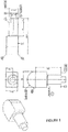
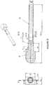
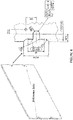
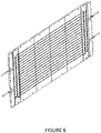
- The drawings refer to embodiments of the invention in which:
- Fig. 1
- - Cu Stub (Component 1)
- Fig. 2
- - Inconel Pipe (Component 2)
- Fig. 3
- - Welding of component 1 and 2 (i.e. Cu stub with Inconel pipe) = Water connector assembly= Sub-assembly 1
- Fig. 4
- - Base plate of Cu plate (Component 4) with weld edge preparation
- Fig. 5
- - EBW welding of component 4 to Sub-assembly 1 (i.e. Cu base plate with Water connector assembly) and drilling operation of the stub through the tubular end to create hydraulic access upto the manifold within the base plate
- Fig. 6
- - Milling operation for cooling channels on angled plane
- Fig. 7
- - Closing of water channel by electro-deposition
- Fig. 8
- - Machining of apertures and scope-out of material.
- Step 1: Machining of a copper stub from copper block
- Step 2: Machining of an Inconel pipe
- Step 3: Electron beam Welding of Copper stub with an Inconel pipe
-
- Acceleration Voltage 120 kV
- Beam Current 9.5mA
- Speed: 10mm/sec
- Working distance 400mm
- Beam Current at focus: 3000mA
- Upslop: 35°
- Overlap: 360°
- Slope off: 18D°
- Outside turning 2mm
- Step 4: Machining of base plate and preparation of pocket (i.e. Weld Edge Preparation) for Machining water connector with respect to reference holes
- Step 5: Electron Beam welding of Base plate and water connector
-
- Acceleration Voltage 130kV
- Beam Current 58-70mA
- Speed 7mm/sec
- Working distance 400mm
- Beam Current at focus: 2035mA
- Upslop:5mm
- Overiap:NA
- Slope off: 4mm
- Outside turning NA
- X-ray examination of welds
- Drilling through the water connector and He Leak test of weld seam
- Step 6: Machining operation for milling of cooling channels on angled plane
- Step 7: Closing of water channels by electro deposition process
-
- He leak test
- Flow test by infrared thermography
- Pressure test
- Thickness measurement of the deposited layer
- Step 8: Machining (drilling) of apertures
-
- Dimensional control of the positioning with respect to reference holes
- Step 9: Welding of Stainless steel tube (external hydraulic circuit) with Inconel extension by orbital TIG welding
-
- Final He leak test, pressure test.
- Although the disclosure hereof is detailed and exact to enable those skilled in the art to practice the invention, the physical embodiments herein disclosed merely exemplify the invention which may be embodied in other specific structure. While the preferred embodiment has been described, the details may be changed without departing from the invention, which is defined by the claims.
- It will be apparent however, to one of ordinary skill in the art that the present invention may be practiced without specific details of the well known components and techniques. In other instances, well known components or methods have not been described in detail but rather in a block diagram in order to avoid unnecessarily obscuring the present Invention. Further specific numeric references should not be interpreted as a literal sequential order. Thus, the specific details set forth are merely exemplary. The specific details may be varied from and still be contemplated to be within the spirit and scope of the present invention. The features discussed In an embodiment may be implemented in another embodiment.
- The present invention provides an Improved method of manufacturing actively cooled accelerator grid with full penetration weld configuration. Thus, the base plate with small machining may adopt the hydraulic feed stubs as a weld inserts In a butt weld configuration. This stub is then welded to the base plate through full penetration Electron beam weld. The stub is then drilled through from Pipe end to create hydraulic access upto the manifold within the base plate. This innovative technique of weld configuration has been applied to the batch manufacturing process and tested for all acceptance parameters. The innovation that Is proposed for protection lies in the configuration of the weld design, process to open-up the access to the hydraulic channel and its novel aspect of full penetration which enables full inspectability. The steps of achieving the objects of the Invention as disclosed aforesaid are clearly disclosed by
Fig.1-9 . - A joint configuration has been successfully welded 'through thickness' resulted in full penetration weld. The joint configuration has been examined 100% volumetrically (radiographic technique) which has revealed the full integrity of this joint. This weld is realized by fusion welding technology without the requirement of grid rotation. This has simplified the machining fixture for the welding (i.e. only planer movement of bed is needed and no rotational / angular movement is required). Further the 'Autogeneous' nature of the technique has eliminated the additional complexity of filler material matching chemistry and related auxiliary accessories. As far as the surface condition of the weld is concerned, negligible post-welding machining is required (practically nil), which allows to use the component in 'as welded' condition. Therefore there is no impact of the welding step on the machining accuracies already achieved on the grid plate surfaces (this is Important for the case of 'angled' grid which are sensitive to each of the manufacturing operations). The configuration provides the correction option (no limitation on cut-and reweld based on the width of plate) by repairing the weld without damaging /wasting the base plate. The process is fully automated such that manual Intervention are totally omitted once the parameters are established, and therefore, the high level of repeatability, consistency is achieved. The configuration also ensures that there is no trapped volume and therefore the chances of virtual leaks under the Ultra High Vacuum (UHV) environment is avoided.
- In one aspect, the qualification of this weld is carried out by subjecting it to various mechanical testing (tensile test, bend test and hardness test) and the properties achieved are as per the functional requirements. Additionally, the joint has been subjected to three times thermal cycling (at temp. of 160 C) followed by pressure test (upto 30 bars) and helium leak tightness (to leak rate better than 1E-9 mbarl/s). Further, the joint has the mechanical properties (strength and ductility) equivalent to that of the base material so provided 100% joint efficiency and design parameters remains unaffected. The full penetration mode do not trap the gases and therefore suitable for vacuum environment where the virtual leaks are not desirable. The development has led to a water tight vacuum boundary joint which fulfills the functional requirement as well as provide the user oriented production process characteristics. The process is suitable for the mass production of grids with highest repeatability, full integrity of joint and vacuum tightness to the UHV level.
- Examples (A few typical examples to illustrate how the invention is carried out in actual practice):
- A prototype grid of the 1:1 size has been manufactured by using the above mentioned technique.
- Real Grid production (17 nos) is in-progress with above mentioned technique.
-
- Weld joint design (square butt with 'U' shape)
- Technique of creating the passage through drilling
- Welding orientation
- Welding technique
- Welding position
-
- Full penetration fusion weld configuration.
- No direct dissimilar welding with base plate and therefore avoiding the metallurigical issues (which otherwise would arise in case of SS to Cu weld joint).
- 100 % volumetrically inspectable which ensures the full integrity and therefore 100% joint efficiency. This keeps the designed parameters unchanged.
- Realized by fusion welding technology without the requirement of grid rotation. This has simplified the machining fixture for the welding (i.e only planer movement of bed is needed and no rotational / angular movement is required). Further the 'Autogeneous' nature of the technique has eliminated the additional complexity of filler material matching chemistry.
- The configuration allows 100% defect detection for complete weld volume by radiography technique and therefore the joint integrity is ensured, established and examination records can be store easily.
- Negligible post-welding machining is required (practically nil), which allows to use the component in 'as welded' condition. Therefore there is no impact of the welding step on the machining accuracies already achieved on the grid plate surfaces (this is important for the case of angled grid which are sensitive to each of the manufacturing operations).
- The configuration provides the correction option by repairing the weld without damaging / wasting the base plate.
- Least amount of manual intervention once the parameters are established and therefore, the high level of repeatability, consistency are achieved.
- UHV compatible water to vacuum boundary (qualified for He leak rate of 1E-9mbarl/s)
- High pressure and high temperature operational parameters (qualified for 30bar and 160 deg C).
-
Parameter Conventional welding process (Friction welding) Present Case (Electron beam welding with full penetration) Joint efficiency 80% 100% Metallurgical compatibility with SS No Yes (through the transition of Inconel Post- welding Machining requirement Yes Nil Volumetric Inspectability by non-destructive examination No (Only surface examination is possible) Yes. Through thickness weld can be examined Rotation of the work piece Yes No Effect on the base plate dimensional accuracies Yes because of the high vibration and rotational effects No. The base plate and connectors rigidly rest on the jig and dimensional accuracies are intact. Possibilities of repair No Yes. Cut and re-weld is feasible. Process reliability and repeatability Low High because of fully automated control of parameters - The foregoing is considered as illustrative only of the principles of the invention. Furthermore, since numerous modifications and changes will readily occur to those skilled In the art, it is not desired to limit the Invention to the exact construction and operation shown and described. While the preferred embodiment has been described, the details may be changed without departing from the invention, which is defined by the claims.
Claims (6)
- An improved method of manufacturing actively cooled accelerator grid with full penetration weld configuration comprising the steps of:a) machining a plurality of stubs;b) machining a first end and a second end of each of a plurality of Inconel pipes;c) welding each of the plurality of the stubs with the first end of the each of the plurality of Inconel pipes, thereby forming a water connector assembly;d) machining of a base plate to prepare plurality of weld edges in 'U' shape in accordance to plurality of reference holes located on the base plate;e) full penetration welding of the base plate with the water connector assembly by electron beam welding;f) machining the base plate welded with the water connector assembly to create a hydraulic passage upto the manifold, wherein machining further comprises milling of plurality of cooling channels across angled plane of the base plate welded with the water connector assembly;g) welding each of plurality of external hydraulic circuits with the second end of the each of the plurality of inconel pipes.
- The method as claimed in claim 1, wherein the each of the plurality of stubs are made of copper;
- The method as claimed in claim 1, wherein the base plate is made of copper;
- The method as claimed in claim 1, wherein the welding is of type electron beam welding.
- The method as claimed in claim 1, wherein the welding the each of the plurality of the external hydraulic circuits with the second end of the each of the plurality of inconel pipes is performed using orbital TIG welding.
- The method as claimed in claim 1 or 5, wherein the plurality of external hydraulic circuit comprises plurality of stainless steel tubes with at least one hollow end, wherein the hollow end is welded with the second end of the each of the plurality of inconel pipes.
Applications Claiming Priority (1)
| Application Number | Priority Date | Filing Date | Title |
|---|---|---|---|
| IN201721023589 | 2017-07-05 |
Publications (2)
| Publication Number | Publication Date |
|---|---|
| EP3424635A1 true EP3424635A1 (en) | 2019-01-09 |
| EP3424635B1 EP3424635B1 (en) | 2022-08-31 |
Family
ID=59846340
Family Applications (1)
| Application Number | Title | Priority Date | Filing Date |
|---|---|---|---|
| EP17188542.9A Active EP3424635B1 (en) | 2017-07-05 | 2017-08-30 | An improved method of manufacturing actively cooled accelerator grid with full penetration weld configuration |
Country Status (2)
| Country | Link |
|---|---|
| US (1) | US10480863B2 (en) |
| EP (1) | EP3424635B1 (en) |
Families Citing this family (1)
| Publication number | Priority date | Publication date | Assignee | Title |
|---|---|---|---|---|
| EP3553797B1 (en) * | 2018-04-13 | 2022-04-20 | Institute for Plasma Research | A method of manufacturing radio frequency (rf) coil multi-driver rf based ion source |
Citations (2)
| Publication number | Priority date | Publication date | Assignee | Title |
|---|---|---|---|---|
| GB2122926A (en) * | 1982-06-30 | 1984-01-25 | Commissariat Energie Atomique | A method for providing a grid for acceleration of ions |
| KR100727680B1 (en) * | 2005-12-26 | 2007-06-13 | 한국원자력연구원 | Large current ion beam drawing electrode with improved cooling circuit and manufacturing method thereof |
Family Cites Families (5)
| Publication number | Priority date | Publication date | Assignee | Title |
|---|---|---|---|---|
| US4841118A (en) * | 1987-03-23 | 1989-06-20 | Combustion Engineering, Inc. | Orbital weld head tool |
| FI114691B (en) * | 2000-02-23 | 2004-12-15 | Outokumpu Oy | Method for forming a connection between copper and stainless steel |
| US8066056B2 (en) * | 2004-05-26 | 2011-11-29 | Sme Products, Lp | Heat exchange system for plume abatement |
| US7921905B2 (en) * | 2006-06-29 | 2011-04-12 | Mahle International Gmbh | Plastic intercooler |
| JP2011246804A (en) * | 2010-04-30 | 2011-12-08 | Nippon Steel Corp | Electronic-beam welding joint and steel for electronic-beam welding, and manufacturing method therefor |
-
2017
- 2017-08-30 EP EP17188542.9A patent/EP3424635B1/en active Active
- 2017-09-20 US US15/709,706 patent/US10480863B2/en not_active Expired - Fee Related
Patent Citations (2)
| Publication number | Priority date | Publication date | Assignee | Title |
|---|---|---|---|---|
| GB2122926A (en) * | 1982-06-30 | 1984-01-25 | Commissariat Energie Atomique | A method for providing a grid for acceleration of ions |
| KR100727680B1 (en) * | 2005-12-26 | 2007-06-13 | 한국원자력연구원 | Large current ion beam drawing electrode with improved cooling circuit and manufacturing method thereof |
Also Published As
| Publication number | Publication date |
|---|---|
| US10480863B2 (en) | 2019-11-19 |
| US20190011188A1 (en) | 2019-01-10 |
| EP3424635B1 (en) | 2022-08-31 |
Similar Documents
| Publication | Publication Date | Title |
|---|---|---|
| CN106624405B (en) | Method and system for repairing damage to tube sheets and tube holes of steam generators in nuclear power plants | |
| CN104526249B (en) | A kind of nuclear power station seal weld repair method and system | |
| CN106808081A (en) | A kind of connection method of aluminium alloy and stainless steel special profile revolving body member | |
| Rathod et al. | Residual stresses in arc and electron-beam welds in 130 mm thick SA508 steel: Part 1-Manufacture | |
| US7617603B2 (en) | Method for inspection and repair | |
| EP3424635B1 (en) | An improved method of manufacturing actively cooled accelerator grid with full penetration weld configuration | |
| Mazul et al. | Technological challenges at ITER plasma facing components production in Russia | |
| US3183066A (en) | Article produced by metals joining and method for producing such articles | |
| Juengert et al. | Nondestructive testing of welds | |
| Hashim et al. | Study on MIG and TIG weldment behaviour using finite element approach | |
| JP5126915B2 (en) | Manufacturing method of non-destructive welding specimens | |
| CN105215565A (en) | The docking calculation that the nuclear power generating equipment low-alloy steel of limited space and stainless steel are taken over | |
| CN106645234A (en) | Automatic discrimination method for space positioning method for defect in fillet weld of T joint | |
| Hernandez-McCloskey et al. | Fabrication of an additively-manufactured chamber for combustion health monitoring in air-breathing rotating detonation flows | |
| Bachmann et al. | Influence of the welding temperature and the welding speed on the mechanical properties of friction stir welds in EN AW-2219-T87 | |
| KR20140004534U (en) | Auto welding apparatus including weding assistance part | |
| CN119124010A (en) | Dissimilar metal joint inspection method, dissimilar metal joint inspection device, welding method and welding system | |
| CN101332529A (en) | Welding process of thin-wall hexagonal tube | |
| BAI et al. | Investigation on three-dimensional real coupling numerical simulation of temperature field of friction stir welding of 2219 aluminum alloy | |
| Herisiswanto et al. | Analysis of Current and Electrode Types on Welding Defects in ASTM A36 Mild Steel | |
| DePaola et al. | Manufacturing of photon beam-intercepting components from CuCrZr | |
| Norajitra et al. | Technological study on manufacturing of multifinger module of He-cooled DEMO divertor and investigation of NDE method | |
| Bałon et al. | Research on welding processes of multi-node aircraft frames and methods for their control | |
| Junghanns et al. | Local copper coating of the connectors of the divertor target elements of Wendelstein 7-X | |
| Visca et al. | Fabrication route of the ANSALDO-ENEA ITER inner vertical target divertor full scale prototype |
Legal Events
| Date | Code | Title | Description |
|---|---|---|---|
| PUAI | Public reference made under article 153(3) epc to a published international application that has entered the european phase |
Free format text: ORIGINAL CODE: 0009012 |
|
| STAA | Information on the status of an ep patent application or granted ep patent |
Free format text: STATUS: THE APPLICATION HAS BEEN PUBLISHED |
|
| AK | Designated contracting states |
Kind code of ref document: A1 Designated state(s): AL AT BE BG CH CY CZ DE DK EE ES FI FR GB GR HR HU IE IS IT LI LT LU LV MC MK MT NL NO PL PT RO RS SE SI SK SM TR |
|
| AX | Request for extension of the european patent |
Extension state: BA ME |
|
| STAA | Information on the status of an ep patent application or granted ep patent |
Free format text: STATUS: REQUEST FOR EXAMINATION WAS MADE |
|
| 17P | Request for examination filed |
Effective date: 20190705 |
|
| RBV | Designated contracting states (corrected) |
Designated state(s): AL AT BE BG CH CY CZ DE DK EE ES FI FR GB GR HR HU IE IS IT LI LT LU LV MC MK MT NL NO PL PT RO RS SE SI SK SM TR |
|
| STAA | Information on the status of an ep patent application or granted ep patent |
Free format text: STATUS: EXAMINATION IS IN PROGRESS |
|
| 17Q | First examination report despatched |
Effective date: 20200506 |
|
| GRAP | Despatch of communication of intention to grant a patent |
Free format text: ORIGINAL CODE: EPIDOSNIGR1 |
|
| STAA | Information on the status of an ep patent application or granted ep patent |
Free format text: STATUS: GRANT OF PATENT IS INTENDED |
|
| INTG | Intention to grant announced |
Effective date: 20220421 |
|
| GRAJ | Information related to disapproval of communication of intention to grant by the applicant or resumption of examination proceedings by the epo deleted |
Free format text: ORIGINAL CODE: EPIDOSDIGR1 |
|
| STAA | Information on the status of an ep patent application or granted ep patent |
Free format text: STATUS: EXAMINATION IS IN PROGRESS |
|
| GRAP | Despatch of communication of intention to grant a patent |
Free format text: ORIGINAL CODE: EPIDOSNIGR1 |
|
| STAA | Information on the status of an ep patent application or granted ep patent |
Free format text: STATUS: GRANT OF PATENT IS INTENDED |
|
| INTC | Intention to grant announced (deleted) | ||
| GRAS | Grant fee paid |
Free format text: ORIGINAL CODE: EPIDOSNIGR3 |
|
| INTG | Intention to grant announced |
Effective date: 20220628 |
|
| GRAA | (expected) grant |
Free format text: ORIGINAL CODE: 0009210 |
|
| STAA | Information on the status of an ep patent application or granted ep patent |
Free format text: STATUS: THE PATENT HAS BEEN GRANTED |
|
| AK | Designated contracting states |
Kind code of ref document: B1 Designated state(s): AL AT BE BG CH CY CZ DE DK EE ES FI FR GB GR HR HU IE IS IT LI LT LU LV MC MK MT NL NO PL PT RO RS SE SI SK SM TR |
|
| REG | Reference to a national code |
Ref country code: CH Ref legal event code: EP Ref country code: GB Ref legal event code: FG4D |
|
| REG | Reference to a national code |
Ref country code: AT Ref legal event code: REF Ref document number: 1514949 Country of ref document: AT Kind code of ref document: T Effective date: 20220915 |
|
| REG | Reference to a national code |
Ref country code: DE Ref legal event code: R096 Ref document number: 602017061172 Country of ref document: DE |
|
| REG | Reference to a national code |
Ref country code: IE Ref legal event code: FG4D |
|
| REG | Reference to a national code |
Ref country code: LT Ref legal event code: MG9D |
|
| REG | Reference to a national code |
Ref country code: NL Ref legal event code: MP Effective date: 20220831 |
|
| PG25 | Lapsed in a contracting state [announced via postgrant information from national office to epo] |
Ref country code: SE Free format text: LAPSE BECAUSE OF FAILURE TO SUBMIT A TRANSLATION OF THE DESCRIPTION OR TO PAY THE FEE WITHIN THE PRESCRIBED TIME-LIMIT Effective date: 20220831 Ref country code: RS Free format text: LAPSE BECAUSE OF FAILURE TO SUBMIT A TRANSLATION OF THE DESCRIPTION OR TO PAY THE FEE WITHIN THE PRESCRIBED TIME-LIMIT Effective date: 20220831 Ref country code: NO Free format text: LAPSE BECAUSE OF FAILURE TO SUBMIT A TRANSLATION OF THE DESCRIPTION OR TO PAY THE FEE WITHIN THE PRESCRIBED TIME-LIMIT Effective date: 20221130 Ref country code: LV Free format text: LAPSE BECAUSE OF FAILURE TO SUBMIT A TRANSLATION OF THE DESCRIPTION OR TO PAY THE FEE WITHIN THE PRESCRIBED TIME-LIMIT Effective date: 20220831 Ref country code: LT Free format text: LAPSE BECAUSE OF FAILURE TO SUBMIT A TRANSLATION OF THE DESCRIPTION OR TO PAY THE FEE WITHIN THE PRESCRIBED TIME-LIMIT Effective date: 20220831 Ref country code: FI Free format text: LAPSE BECAUSE OF FAILURE TO SUBMIT A TRANSLATION OF THE DESCRIPTION OR TO PAY THE FEE WITHIN THE PRESCRIBED TIME-LIMIT Effective date: 20220831 |
|
| REG | Reference to a national code |
Ref country code: AT Ref legal event code: MK05 Ref document number: 1514949 Country of ref document: AT Kind code of ref document: T Effective date: 20220831 |
|
| PG25 | Lapsed in a contracting state [announced via postgrant information from national office to epo] |
Ref country code: PL Free format text: LAPSE BECAUSE OF FAILURE TO SUBMIT A TRANSLATION OF THE DESCRIPTION OR TO PAY THE FEE WITHIN THE PRESCRIBED TIME-LIMIT Effective date: 20220831 Ref country code: IS Free format text: LAPSE BECAUSE OF FAILURE TO SUBMIT A TRANSLATION OF THE DESCRIPTION OR TO PAY THE FEE WITHIN THE PRESCRIBED TIME-LIMIT Effective date: 20221231 Ref country code: HR Free format text: LAPSE BECAUSE OF FAILURE TO SUBMIT A TRANSLATION OF THE DESCRIPTION OR TO PAY THE FEE WITHIN THE PRESCRIBED TIME-LIMIT Effective date: 20220831 Ref country code: GR Free format text: LAPSE BECAUSE OF FAILURE TO SUBMIT A TRANSLATION OF THE DESCRIPTION OR TO PAY THE FEE WITHIN THE PRESCRIBED TIME-LIMIT Effective date: 20221201 |
|
| PG25 | Lapsed in a contracting state [announced via postgrant information from national office to epo] |
Ref country code: SM Free format text: LAPSE BECAUSE OF FAILURE TO SUBMIT A TRANSLATION OF THE DESCRIPTION OR TO PAY THE FEE WITHIN THE PRESCRIBED TIME-LIMIT Effective date: 20220831 Ref country code: RO Free format text: LAPSE BECAUSE OF FAILURE TO SUBMIT A TRANSLATION OF THE DESCRIPTION OR TO PAY THE FEE WITHIN THE PRESCRIBED TIME-LIMIT Effective date: 20220831 Ref country code: PT Free format text: LAPSE BECAUSE OF FAILURE TO SUBMIT A TRANSLATION OF THE DESCRIPTION OR TO PAY THE FEE WITHIN THE PRESCRIBED TIME-LIMIT Effective date: 20230102 Ref country code: ES Free format text: LAPSE BECAUSE OF FAILURE TO SUBMIT A TRANSLATION OF THE DESCRIPTION OR TO PAY THE FEE WITHIN THE PRESCRIBED TIME-LIMIT Effective date: 20220831 Ref country code: DK Free format text: LAPSE BECAUSE OF FAILURE TO SUBMIT A TRANSLATION OF THE DESCRIPTION OR TO PAY THE FEE WITHIN THE PRESCRIBED TIME-LIMIT Effective date: 20220831 Ref country code: CZ Free format text: LAPSE BECAUSE OF FAILURE TO SUBMIT A TRANSLATION OF THE DESCRIPTION OR TO PAY THE FEE WITHIN THE PRESCRIBED TIME-LIMIT Effective date: 20220831 Ref country code: AT Free format text: LAPSE BECAUSE OF FAILURE TO SUBMIT A TRANSLATION OF THE DESCRIPTION OR TO PAY THE FEE WITHIN THE PRESCRIBED TIME-LIMIT Effective date: 20220831 |
|
| PG25 | Lapsed in a contracting state [announced via postgrant information from national office to epo] |
Ref country code: SK Free format text: LAPSE BECAUSE OF FAILURE TO SUBMIT A TRANSLATION OF THE DESCRIPTION OR TO PAY THE FEE WITHIN THE PRESCRIBED TIME-LIMIT Effective date: 20220831 Ref country code: EE Free format text: LAPSE BECAUSE OF FAILURE TO SUBMIT A TRANSLATION OF THE DESCRIPTION OR TO PAY THE FEE WITHIN THE PRESCRIBED TIME-LIMIT Effective date: 20220831 |
|
| REG | Reference to a national code |
Ref country code: DE Ref legal event code: R097 Ref document number: 602017061172 Country of ref document: DE |
|
| PG25 | Lapsed in a contracting state [announced via postgrant information from national office to epo] |
Ref country code: NL Free format text: LAPSE BECAUSE OF FAILURE TO SUBMIT A TRANSLATION OF THE DESCRIPTION OR TO PAY THE FEE WITHIN THE PRESCRIBED TIME-LIMIT Effective date: 20220831 Ref country code: AL Free format text: LAPSE BECAUSE OF FAILURE TO SUBMIT A TRANSLATION OF THE DESCRIPTION OR TO PAY THE FEE WITHIN THE PRESCRIBED TIME-LIMIT Effective date: 20220831 |
|
| PLBE | No opposition filed within time limit |
Free format text: ORIGINAL CODE: 0009261 |
|
| STAA | Information on the status of an ep patent application or granted ep patent |
Free format text: STATUS: NO OPPOSITION FILED WITHIN TIME LIMIT |
|
| 26N | No opposition filed |
Effective date: 20230601 |
|
| PG25 | Lapsed in a contracting state [announced via postgrant information from national office to epo] |
Ref country code: SI Free format text: LAPSE BECAUSE OF FAILURE TO SUBMIT A TRANSLATION OF THE DESCRIPTION OR TO PAY THE FEE WITHIN THE PRESCRIBED TIME-LIMIT Effective date: 20220831 |
|
| REG | Reference to a national code |
Ref country code: DE Ref legal event code: R119 Ref document number: 602017061172 Country of ref document: DE |
|
| PG25 | Lapsed in a contracting state [announced via postgrant information from national office to epo] |
Ref country code: MC Free format text: LAPSE BECAUSE OF FAILURE TO SUBMIT A TRANSLATION OF THE DESCRIPTION OR TO PAY THE FEE WITHIN THE PRESCRIBED TIME-LIMIT Effective date: 20220831 |
|
| REG | Reference to a national code |
Ref country code: CH Ref legal event code: PL |
|
| PG25 | Lapsed in a contracting state [announced via postgrant information from national office to epo] |
Ref country code: MC Free format text: LAPSE BECAUSE OF FAILURE TO SUBMIT A TRANSLATION OF THE DESCRIPTION OR TO PAY THE FEE WITHIN THE PRESCRIBED TIME-LIMIT Effective date: 20220831 |
|
| PG25 | Lapsed in a contracting state [announced via postgrant information from national office to epo] |
Ref country code: LU Free format text: LAPSE BECAUSE OF NON-PAYMENT OF DUE FEES Effective date: 20230830 |
|
| GBPC | Gb: european patent ceased through non-payment of renewal fee |
Effective date: 20230830 |
|
| PG25 | Lapsed in a contracting state [announced via postgrant information from national office to epo] |
Ref country code: LU Free format text: LAPSE BECAUSE OF NON-PAYMENT OF DUE FEES Effective date: 20230830 Ref country code: CH Free format text: LAPSE BECAUSE OF NON-PAYMENT OF DUE FEES Effective date: 20230831 |
|
| REG | Reference to a national code |
Ref country code: BE Ref legal event code: MM Effective date: 20230831 |
|
| REG | Reference to a national code |
Ref country code: IE Ref legal event code: MM4A |
|
| PG25 | Lapsed in a contracting state [announced via postgrant information from national office to epo] |
Ref country code: IE Free format text: LAPSE BECAUSE OF NON-PAYMENT OF DUE FEES Effective date: 20230830 |
|
| PG25 | Lapsed in a contracting state [announced via postgrant information from national office to epo] |
Ref country code: GB Free format text: LAPSE BECAUSE OF NON-PAYMENT OF DUE FEES Effective date: 20230830 |
|
| PG25 | Lapsed in a contracting state [announced via postgrant information from national office to epo] |
Ref country code: IT Free format text: LAPSE BECAUSE OF NON-PAYMENT OF DUE FEES Effective date: 20230830 Ref country code: IE Free format text: LAPSE BECAUSE OF NON-PAYMENT OF DUE FEES Effective date: 20230830 Ref country code: GB Free format text: LAPSE BECAUSE OF NON-PAYMENT OF DUE FEES Effective date: 20230830 Ref country code: FR Free format text: LAPSE BECAUSE OF NON-PAYMENT OF DUE FEES Effective date: 20230831 Ref country code: DE Free format text: LAPSE BECAUSE OF NON-PAYMENT OF DUE FEES Effective date: 20240301 |
|
| PG25 | Lapsed in a contracting state [announced via postgrant information from national office to epo] |
Ref country code: BE Free format text: LAPSE BECAUSE OF NON-PAYMENT OF DUE FEES Effective date: 20230831 |
|
| PG25 | Lapsed in a contracting state [announced via postgrant information from national office to epo] |
Ref country code: BG Free format text: LAPSE BECAUSE OF FAILURE TO SUBMIT A TRANSLATION OF THE DESCRIPTION OR TO PAY THE FEE WITHIN THE PRESCRIBED TIME-LIMIT Effective date: 20220831 |
|
| PG25 | Lapsed in a contracting state [announced via postgrant information from national office to epo] |
Ref country code: BG Free format text: LAPSE BECAUSE OF FAILURE TO SUBMIT A TRANSLATION OF THE DESCRIPTION OR TO PAY THE FEE WITHIN THE PRESCRIBED TIME-LIMIT Effective date: 20220831 |
|
| PG25 | Lapsed in a contracting state [announced via postgrant information from national office to epo] |
Ref country code: CY Free format text: LAPSE BECAUSE OF FAILURE TO SUBMIT A TRANSLATION OF THE DESCRIPTION OR TO PAY THE FEE WITHIN THE PRESCRIBED TIME-LIMIT; INVALID AB INITIO Effective date: 20170830 |
|
| PG25 | Lapsed in a contracting state [announced via postgrant information from national office to epo] |
Ref country code: HU Free format text: LAPSE BECAUSE OF FAILURE TO SUBMIT A TRANSLATION OF THE DESCRIPTION OR TO PAY THE FEE WITHIN THE PRESCRIBED TIME-LIMIT; INVALID AB INITIO Effective date: 20170830 |
|
| PG25 | Lapsed in a contracting state [announced via postgrant information from national office to epo] |
Ref country code: TR Free format text: LAPSE BECAUSE OF FAILURE TO SUBMIT A TRANSLATION OF THE DESCRIPTION OR TO PAY THE FEE WITHIN THE PRESCRIBED TIME-LIMIT Effective date: 20220831 |
|
| PG25 | Lapsed in a contracting state [announced via postgrant information from national office to epo] |
Ref country code: MT Free format text: LAPSE BECAUSE OF NON-PAYMENT OF DUE FEES Effective date: 20230830 |