EP3424634A1 - Welding torch - Google Patents
Welding torch Download PDFInfo
- Publication number
- EP3424634A1 EP3424634A1 EP17759895.0A EP17759895A EP3424634A1 EP 3424634 A1 EP3424634 A1 EP 3424634A1 EP 17759895 A EP17759895 A EP 17759895A EP 3424634 A1 EP3424634 A1 EP 3424634A1
- Authority
- EP
- European Patent Office
- Prior art keywords
- suction nozzle
- welding
- tip
- shielding gas
- nozzle
- Prior art date
- Legal status (The legal status is an assumption and is not a legal conclusion. Google has not performed a legal analysis and makes no representation as to the accuracy of the status listed.)
- Granted
Links
Images







Classifications
-
- B—PERFORMING OPERATIONS; TRANSPORTING
- B23—MACHINE TOOLS; METAL-WORKING NOT OTHERWISE PROVIDED FOR
- B23K—SOLDERING OR UNSOLDERING; WELDING; CLADDING OR PLATING BY SOLDERING OR WELDING; CUTTING BY APPLYING HEAT LOCALLY, e.g. FLAME CUTTING; WORKING BY LASER BEAM
- B23K9/00—Arc welding or cutting
- B23K9/16—Arc welding or cutting making use of shielding gas
- B23K9/173—Arc welding or cutting making use of shielding gas and of a consumable electrode
-
- B—PERFORMING OPERATIONS; TRANSPORTING
- B23—MACHINE TOOLS; METAL-WORKING NOT OTHERWISE PROVIDED FOR
- B23K—SOLDERING OR UNSOLDERING; WELDING; CLADDING OR PLATING BY SOLDERING OR WELDING; CUTTING BY APPLYING HEAT LOCALLY, e.g. FLAME CUTTING; WORKING BY LASER BEAM
- B23K9/00—Arc welding or cutting
- B23K9/16—Arc welding or cutting making use of shielding gas
- B23K9/164—Arc welding or cutting making use of shielding gas making use of a moving fluid
-
- B—PERFORMING OPERATIONS; TRANSPORTING
- B23—MACHINE TOOLS; METAL-WORKING NOT OTHERWISE PROVIDED FOR
- B23K—SOLDERING OR UNSOLDERING; WELDING; CLADDING OR PLATING BY SOLDERING OR WELDING; CUTTING BY APPLYING HEAT LOCALLY, e.g. FLAME CUTTING; WORKING BY LASER BEAM
- B23K9/00—Arc welding or cutting
- B23K9/24—Features related to electrodes
- B23K9/26—Accessories for electrodes, e.g. ignition tips
-
- B—PERFORMING OPERATIONS; TRANSPORTING
- B23—MACHINE TOOLS; METAL-WORKING NOT OTHERWISE PROVIDED FOR
- B23K—SOLDERING OR UNSOLDERING; WELDING; CLADDING OR PLATING BY SOLDERING OR WELDING; CUTTING BY APPLYING HEAT LOCALLY, e.g. FLAME CUTTING; WORKING BY LASER BEAM
- B23K9/00—Arc welding or cutting
- B23K9/24—Features related to electrodes
- B23K9/28—Supporting devices for electrodes
- B23K9/29—Supporting devices adapted for making use of shielding means
-
- B—PERFORMING OPERATIONS; TRANSPORTING
- B23—MACHINE TOOLS; METAL-WORKING NOT OTHERWISE PROVIDED FOR
- B23K—SOLDERING OR UNSOLDERING; WELDING; CLADDING OR PLATING BY SOLDERING OR WELDING; CUTTING BY APPLYING HEAT LOCALLY, e.g. FLAME CUTTING; WORKING BY LASER BEAM
- B23K9/00—Arc welding or cutting
- B23K9/24—Features related to electrodes
- B23K9/28—Supporting devices for electrodes
- B23K9/29—Supporting devices adapted for making use of shielding means
- B23K9/291—Supporting devices adapted for making use of shielding means the shielding means being a gas
- B23K9/295—Supporting devices adapted for making use of shielding means the shielding means being a gas using consumable wire electrodes
-
- B—PERFORMING OPERATIONS; TRANSPORTING
- B23—MACHINE TOOLS; METAL-WORKING NOT OTHERWISE PROVIDED FOR
- B23K—SOLDERING OR UNSOLDERING; WELDING; CLADDING OR PLATING BY SOLDERING OR WELDING; CUTTING BY APPLYING HEAT LOCALLY, e.g. FLAME CUTTING; WORKING BY LASER BEAM
- B23K9/00—Arc welding or cutting
- B23K9/32—Accessories
- B23K9/325—Devices for supplying or evacuating shielding gas
Definitions
- the present invention relates to a welding torch.
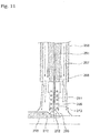
- Fig. 11 is a diagram for illustrating a process in which diffusible hydrogen is absorbed by a weld metal.
- a flux cored wire which is a welding wire containing a flux is used as a welding wire.
- Fig. 12 is a view showing a cross-section of the flux cored wire.
- a welding wire 201 which is a flux cored wire, includes a steel hoop 202 forming the outer periphery, and a central portion 203.
- the central portion 203 contains a metal powder of a metal or alloy, and a flux.
- the welding wire 201 is fed through a contact tip 208, and simultaneously, a welding current passes from the contact tip 208 to the welding wire 201, so that the welding wire 201 is melted by an arc 209 at the tip of the welding wire 201 to form a weld metal 210.
- a welding current passes through a wire protrusion portion 211 of the welding wire 201, which is protruded from the contact tip 208, and therefore resistance heat generation occurs, so that the temperature is elevated.
- the elevated temperature reaches 100°C at a point about 5 mm away from the tip of the contact tip 208, and may be elevated to about 600°C in the vicinity of a wire tip 20 mm away from the tip of the contact tip 208.
- a hydrogen source 205 on the wire surface is vaporized, and discharged from the welding wire 201.
- the central portion 203 is heated by conduction of heat from the heated steel hoop 202, the hydrogen source 205 in the flux and in the metal powder is also vaporized, and discharged to the outside of the welding wire 201 through a seam 204 as a joint.
- the hydrogen source 205 e.g. H 2 O
- the hydrogen source present on the wire surface and/or the hydrogen source contained in a flux and metal powder used for the welding wire are vaporized in the wire protrusion portion heated to a high temperature.
- the vaporized hydrogen source is carried to the inside of the arc column and the vicinity thereof by the arc plasma stream, and the flow of the shielding gas supplied in the case of gas shielding arc welding.
- the carried hydrogen source is dissociated into hydrogen atoms (i.e. diffusible hydrogen), and absorbed into the weld metal.
- preheating heatating of a weld steel material before welding
- post-heating heatating of a welded portion after welding
- fluorides such as CaF2 and/or Na 3 AlF 6 are added to a flux to reduce diffusible hydrogen.
- a method has also been proposed in which a very small amount of CF 4 is mixed with a shielding gas supplied in gas shielding arc welding.
- Patent Document 1 JP 2002-506736 A
- Hydrogen sources in a welding wire include oil and moisture deposited on a wire surface, and moisture and organic substances deposited on a flux and metal powder included in a flux cored wire and/or a metal cored wire.
- the amount of the hydrogen source deposited on a flux and/or metal powder is larger than the amount of the hydrogen source deposited on a welding wire surface.
- a method may be employed in which before production of a welding wire, the flux and metal particles are heated at a high temperature to remove the hydrogen source.
- prevention of absorption of moisture in a production process is necessary, but requires an enormous cost. Further, even after commercialization, moisture is adsorbed from air during storage and operation at a high-humidity welding site, and thus there are various obstacles to reduction of the hydrogen source.
- preheating and/or post-heating that is performed as measures against hydrogen embrittlement and hydrogen cracking involves heating at 150 to 250°C, and thus requires an enormous energy cost and labor.
- high-temperature operation is required, and thus a heavy burden is put on welding operators.
- CF 4 is mixed with a shielding gas has a safety problem and a problem of deterioration of the stability of an arc, and there may be an obstacle to wide use of the method.
- Patent Document 1 sucks fumes from an opening portion that surrounds the periphery of a welding wire protruded from a contact tip, and faces a wire tip portion. It is thought that in this torch, a hydrogen source desorbed from the welding wire during welding is sucked together with fumes, and discharged to the outside of a welded portion to reduce the amount of diffusible hydrogen in a weld metal, although this is not described in Patent Document 1.
- Patent Document 1 shows only a rough configuration of the torch, and does not describe a detailed configuration including the sizes and relative positions of nozzles and tips.
- the torch may have an optimal configuration from the viewpoints of hydrogen suction performance, prevention of pore defects of a weld metal, and protection of torch components, but Patent Document 1 does not suggest such an optimal configuration. Since pursuit of hydrogen suction performance leads to a structure that cannot endure long-time use, a proper design is required. In addition, depending on the structure of a suction nozzle, the flow condition of a shielding gas is deteriorated, and therefore shielding property is deteriorated, so that air is entrained, leading to generation of pore defects.
- the present disclosure has been made in view of the above-described circumstances, and an object of the present disclosure is to provide a welding torch capable of improving welding quality by exhibiting high hydrogen suction performance while protecting the welding torch.
- An example of the present invention provides a welding torch which performs arc welding in a shielding gas atmosphere, the welding torch comprising: a contact tip that supports a welding wire which is supplied with a welding current while the welding wire can be fed toward a tip portion; a suction nozzle that surrounds a periphery of the welding wire protruded from a tip portion of the contact tip, and sucks a gas from a space formed between the suction nozzle and the welding wire; and a shielding gas supply nozzle that is provided on an outer periphery of the suction nozzle, and supplies the shielding gas toward a welded portion at a tip of the welding wire from a space formed between the shielding gas supply nozzle and the suction nozzle, wherein where Lts [mm] is a distance along a welding wire longitudinal direction between a tip of the contact tip and a tip of the shielding gas supply nozzle, and Ltk [mm] is a distance along the welding wire longitudinal direction between the tip of the contact tip and a tip
- welding quality can be improved by exhibiting high hydrogen suction performance to prevent generation of pore defects etc. of a weld metal while protecting a welding torch.
- a welding apparatus 10 is an apparatus that performs welding by consumable electrode type gas shielding arc welding.
- the consumable electrode is an electrode that is melted by arc heat in arc welding.
- the gas shielding arc welding is a welding method in which welding is performed with a welded portion shielded from outside air by an injected shielding gas.
- the welding apparatus 10 performs welding while sucking a shielding gas containing a hydrogen source 11 in the vicinity of the wire protrusion portion in the shielding gas injected to the welded portion.
- Fig. 1 is a diagram showing one example of a schematic configuration of the welding apparatus 10 according to an embodiment.
- the welding apparatus 10 of this configuration example includes a welding torch 100 that welds a workpiece W using a welding wire 13; and a suction apparatus 15 that sucks a shielding gas.
- the welding apparatus 10 includes a suction shielding gas channel 17 connecting the welding torch 100 and the suction apparatus 15.
- the welding torch 100 welds the workpiece W by feeding a welding wire 13 with a welding current supplied from a welding power source (not shown).
- a welding wire 13 for example, a flux cored wire having a metal powder and a flux at a central portion, a metal cored wire having mainly a metal powder at a center portion, or a solid wire composed of an alloy such as steel is used.
- the welding torch 100 includes a shielding gas supply nozzle 21, a suction nozzle 23, a contact tip 25, a suction channel 27, and a tip body 29. Further, an insulating component 28 for insulating the shielding gas supply nozzle 21 and the tip body 29 is provided between the shielding gas supply nozzle 21 and the tip body 29.
- the suction apparatus 15 includes a flow rate control valve 31 and an ejector 33, and sucks a shielding gas from the suction nozzle 23 of the welding torch 100.
- the shielding gas is supplied to the shielding gas supply nozzle 21 from an external shielding gas supply apparatus (not shown) such as a shielding gas cylinder. It suffices that the suction apparatus 15 has a suction capacity of, for example, about 25L/min. It is possible to employ a suction apparatus which is small in size and available at a low cost rather than one requiring a large amount of energy.
- the suction shielding gas channel 17 connects the suction channel 27 of the welding torch 100 to the suction apparatus 15 to form a channel through which the sucked shielding gas flows.
- the suction shielding gas channel 17 is formed of, for example, a rubber tube.
- the shielding gas supply nozzle 21 has a tubular shape, and is fitted and fixed to the tubularly formed tip body 29 from the lower side in Fig. 1 .
- the insulating resin component 28 is provided on an outer peripheral surface 29a of the tip body 29 on the upper side in the drawing, so that the shielding gas supply nozzle 21 and the tip body 29 are insulated from each other.
- the shielding gas supply nozzle 21 supplies a shielding gas to the welded portion.
- the shielding gas supply nozzle 21 is tubularly formed, the shielding gas is supplied in such a manner that the welded portion is surrounded and shielded from outside air.
- the suction nozzle 23 is disposed in the shielding gas supply nozzle 21, and has a tubular shape.
- the suction nozzle 23 is fitted and fixed to the outer peripheral surface 29b of the tubular portion of the tip body 29, which is protruded to the lower side in Fig. 1 .
- An orifice 30 serving as a throttle for making uniform the shielding gas sent from a shielding gas supply apparatus is disposed between the shielding gas supply nozzle 21 and the outer peripheral surface 29b of the tip body 29 connected to the suction nozzle 23.
- the suction nozzle 23 is structured to surround the periphery of a wire protrusion portion 37 of the welding wire 13, which is protruded from the contact tip 25, and the suction nozzle 23 has an opening portion 39 extending toward the tip portion of the welding wire 13.
- Fig. 2 is a sectional view taken along line A-A in Fig. 1 in the welding apparatus 10. As shown in Fig. 2 , a welding wire 13 is provided at the center of the contact tip 25, and the suction nozzle 23 exists so as to surround the periphery of the contact tip 25. In addition, the shielding gas supply nozzle 21 is provided so as to surround the periphery of the suction nozzle 23.
- the suction nozzle 23 is opened toward the tip of the welding wire 13, i.e. along a direction in which an arc 41 is generated.
- the suction nozzle is configured to suck a shielding gas including the hydrogen source 11 discharged in the vicinity of the wire tip portion.
- the shielding gas including the hydrogen source 11 is discharged to the outside of the welded portion by flowing in a direction of arrow 43, which is a direction in which the shielding gas goes toward the outside of the welded portion.
- the suction nozzle 23 may be configured to have such a large length that even the wire tip portion is surrounded, but there is the possibility that the suction nozzle 23 is melted by arc heat.
- the suction nozzle 23 is configured to be opened toward the wire tip portion while having a length determined with consideration given to influences of arc heat.
- a copper alloy excellent in heat conduction, or a ceramic excellent in heat resistance is used.
- one subjected to chromium plating or the like for preventing deposition of spatters may be used.
- the contact tip 25 is disposed on an inner diameter portion of the suction nozzle 23, and has a tubular shape.
- the contact tip 25 is fixed by fitting a contact tip upper portion to an inner diameter portion 29c of the tip body 29 on the lower side in Fig. 1 .
- the contact tip 25 guides the welding wire 13, and supplies a welding current to the welding wire 13.
- a wire feeding channel having a diameter that allows the wire feeding channel to come into contact with the welding wire 13 is formed, and power is supplied to the welding wire 13.
- the contact tip 25 is detachably attached to the tip body 29, and is replaced when worn due to long-time use.
- the suction channel 27 guides the shielding gas sucked by the suction nozzle 23 to the suction apparatus 15.
- This suction channel 27 includes passages formed by boring four holes with a diameter of, for example, about 1.5 mm in the tip body 29 using a drill, and the passages formed by the four holes are joined in a circumferential joining groove 45, and then connected to the suction apparatus 15 through the suction shielding gas channel 17.
- the suction channel 27 does not necessarily have such a configuration, and may have any configuration as long as it forms a channel that guides the shielding gas and/or hydrogen source 11 from the suction nozzle 23 to the suction apparatus 15.
- the tip body 29 is a main body portion of the welding torch 100.
- the tip body 29 has a tubular shape, and supports the shielding gas supply nozzle 21, the suction nozzle 23, and the contact tip 25 which are connected through the insulating resin component 28.
- the flow rate control valve 31 is formed by, for example, a needle valve, includes an actuator such as a motor (not shown), and controls a suction flow rate.
- the flow rate control valve 31 is provided between a suction port 47 of the ejector 33 as described later and the suction shielding gas channel 17.
- the ejector 33 is in the form of a T-shaped tube, and has a function of a general ejector. That is, when a drive gas such as compressed air flows in a horizontal direction, the flow velocity is increased at a portion having a small diameter in the tube, and a tube corresponding to the vertical line of the T shape serves as a suction port, so that a shielding gas is sucked through the suction nozzle 23.
- the ejector 33 includes a drive nozzle 52, a gas supply port 51, a suction port 47, and an exhaust port 35.
- a drive gas such as compressed air is supplied to the gas supply port 51.
- the drive gas guided from the gas supply port 51 to the drive nozzle 52 is ejected toward the exhaust port 35.
- a suction force acts on the suction port 47, and the shielding gas including the hydrogen source 11 is guided to the suction port 47 from the suction nozzle 23 connected through the suction shielding gas channel 17 and the suction channel 27.
- the sucked shielding gas including the hydrogen source 11 in the suction port 47 is sent to the exhaust port 35.
- the suction apparatus 15 performs suction on the periphery of the wire protrusion portion 37 and in the vicinity of the tip portion of the welding wire 13 by the suction nozzle 23.
- the shielding gas including the hydrogen source 11 discharged from the heated welding wire 13 flows in a direction of arrow 43, which is a direction in which the shielding gas goes toward the outside of the welded portion and is sucked.
- the hydrogen source 11 is situated just above the arc 41, and therefore most of the hydrogen source 11 is guided to the arc 41, and absorbed into the weld metal.
- the required preheating temperature can be lowered by about 25°C by decreasing the amount of diffusible hydrogen in a weld metal by 1 mL/100 g.
- the preheating temperature can be lowered by 100°C in welding requiring a preheating temperature of 125°C, so that the preheating temperature is lowered to 25°C, resulting in elimination of necessity of preheating.
- the preheating temperature is 100°C or lower.
- the welding wire 13 absorbs moisture depending on the storage environment, but whether the welding wire 13 absorbs moisture is not known by visual observation, and therefore thorough management of the storage environment is required.
- the amount of diffusible hydrogen in the weld metal decreases, and therefore the level of management of the storage environment is reduced, so that even if absorption of moisture occurs due to a human mistake, influences of such a mistake are relaxed.
- Fig. 3 is an enlarged view of a main part of the tip portion of the welding torch shown in Fig. 1 .
- the welding torch 100 of this configuration example performs arc welding in a shielding gas atmosphere.
- the welding torch includes: the contact tip 25 that supports a welding wire which is supplied with a welding current while the welding wire can be fed toward a tip portion; the suction nozzle 23 that surrounds a periphery of the welding wire protruded from a tip portion of the contact tip 25, and sucks a gas from a space formed between the suction nozzle 23 and the welding wire; and the shielding gas supply nozzle 21 that is provided on an outer periphery of the suction nozzle 23, and supplies the shielding gas toward a welded portion at a tip of the welding wire from a space formed between the shielding gas supply nozzle 21 and the suction nozzle 23.
- the contact tip 25, the shielding gas supply nozzle 21, and the suction nozzle 23 in the welding torch 100 has the following positional relationship.
- Lts [mm] is a distance along a welding wire longitudinal direction between the tip of the contact tip 25 and the tip of the shielding gas supply nozzle 21
- Ltk [mm] is a distance along the welding wire longitudinal direction between the tip of the contact tip 25 and the tip of the suction nozzle 23
- the distance Ltk is preferably 9 or more, and preferably 15 or less, more preferably 14 or less.
- the distance Lts is preferably 4 or more, and preferably 16 or less, more preferably 15 or less.
- the welding torch 100 satisfies the relationship of the following formula regarding the diameters of the shielding gas supply nozzle 21 and the suction nozzle 23.
- Dsi [mm] is an inner diameter of the shielding gas supply nozzle 21
- Dki [mm] is an inner diameter of the suction nozzle 23
- Dko [mm] is an outer diameter of the suction nozzle 23
- the welding torch 100 satisfies the relationship of the formula (2).
- the difference Dsi-Dko between the inner diameter Dsi of the shielding gas supply nozzle 21 and the outer diameter Dko of the suction nozzle 23 is preferably 3 or more.
- the difference Dko-Dki is preferably 2 or more.
- the inner diameter Dsi of the shielding gas supply nozzle 21 is preferably 13 or more, and more preferably 35 or less.
- the inner diameter Dki of the suction nozzle 23 is preferably 1.8 or more, and more preferably 8 or less.
- the largest of the distances along the welding wire longitudinal direction between the tip of the contact tip 25 and the tips of the suction nozzles 23 is defined as the distance Ltk.
- the welding torch 100 has an electric resistance of 50 ⁇ or more between the tip body 29 and the tip of the suction nozzle 23.
- the electric resistance is more preferably 500 ⁇ or more.
- the surface roughness of the inner surface of the suction nozzle in the welding torch 100 satisfies the relationship of following formula.
- Ra [ ⁇ m] is an arithmetic mean roughness of the inner surface of the suction nozzle
- the surface roughness Ra of the nozzle inner peripheral surface in the suction nozzle 23 of the welding torch 100 satisfies the relationship of 0.05 ⁇ Ra ⁇ 50.
- the arithmetic mean roughness Ra is preferably 20 or less, more preferably 10 or less. In addition, the arithmetic mean roughness Ra is preferably 0.3 or more, more preferably 1 or more.
- the distance Ltk is preferably 10 - 0.4 ⁇ Qk or more.
- the flow velocity Vs is preferably 5 or less, more preferably 4 or less.
- Fig. 4 is an enlarged view of a main part of a welding torch according to a modification in which the suction nozzle 23 has a taper.
- a suction nozzle 23A is formed so as to have a taper in which the diameter gradually decreases as going toward the tip. Since the suction nozzle 23A has a taper, the flow velocity at the suction channel 27 can be gradually increased as going toward the tip opening.
- a space formed between the outer periphery of the suction nozzle 23A and the shielding gas supply nozzle 21 can be expanded by forming the suction nozzle 23A with a taper. Accordingly, the flow velocity Vs at the shielding gas outlet can be easily set within a preferred range.
- Fig. 5 is an enlarged view of a main part of a welding torch according to a modification in which the shape of the tip portion of a suction nozzle 23B is changed.
- the outer peripheral surface 29b of the tip body 29 supports the suction nozzle 23B, and the inner diameter portion 29c of the tip body 29 supports the contact tip 25.
- the inner surface of the tip portion of each of the suction nozzles 23 and 23A is formed so as to decrease the diameter to the inner periphery side and have a large thickness, but the tip portion may be formed with the same thickness as that of the other portions as in the suction nozzle 23B shown in Fig. 5 .
- the welding torch 100 sucks a part of the shielding gas for reducing the amount of diffusible hydrogen in the weld metal.
- matters to be noted include hydrogen suction performance, prevention of generation of pore defects in the weld metal, and protection of torch components.
- the welding wire 13 delivered from the contact tip 25 is fed with a welding current from this moment, and therefore undergoes generation of Joule heat, so that the temperature is elevated.
- the temperature is elevated as the distance between the welding wire 13 and the contact tip 25 increases.
- the discharge rate of the hydrogen source 11 discharged from the welding wire 13 increases as the amount of applied energy increases.
- the suction nozzle 23 covers the welding wire 13 up to a position at which the wire temperature is further elevated. That is, in the suction nozzle 23, the distance Ltk along the welding wire longitudinal direction between the tip of the contact tip 25 and the tip of the suction nozzle 23 is preferably long.
- the hydrogen source 11 discharged at a position distant from the suction nozzle 23 by a flow at the tip of the nozzle can also be sucked.
- the inventors have derived a relational formula between the preferred suction flow rate and the suction nozzle position (see the foregoing formula (3)) through an experiment.
- the surface roughness of the inner surface of the suction nozzle in the welding torch 100 is preferably small.
- the shielding property of the welded portion is deteriorated as compared to general gas shielding arc welding.
- the shielding property is deteriorated, there arise problems of generation of pore defects in the weld metal, and so on.
- the positions of the shield nozzle tip and the workpiece W are preferably close to each other.
- the distance between the contact tip 25 and the workpiece W is adjusted to about 20 to 30 mm from the viewpoint of welding operability.
- the tip of the suction nozzle has a potential equal to that of the welding wire 13.
- sparking may occur between the suction nozzle and the workpiece, resulting in erosion of the suction nozzle 23.
- the welding torch 100 having this configuration, erosion due to inadvertent sparking can be prevented because the shield nozzle is long, and the suction nozzle 23 is substantially covered.
- the layer thickness of the gas which secures shielding property decreases, so that ingress of outside air into the inner part easily occurs.
- the flow velocity and the flow rate of the shielding gas may be related to securement of shielding property, and it has been confirmed that when the difference between the inner diameter Dsi of the shielding gas supply nozzle 21 and the outer diameter Dko of the suction nozzle 23 is set within a predetermined range under the supply of the shielding gas at an appropriate flow rate, shielding property is improved.
- the shielding gas is sent in a laminar flow state with little involvement of an ambient gas.
- the shielding gas flow velocity at the outlet of the shielding gas supply nozzle 21 increases, so that the shielding gas is brought into a turbulent flow state even when the shielding gas is supplied at an appropriate flow rate.
- air is excessively involved.
- the approximate value of the flow velocity at the gas outlet of the shielding gas supply nozzle 21 in the welding torch 100 is preferably low.
- the distance Ltk is preferably long, and on the other hand, the distance between the workpiece W and the suction nozzle 23 is preferably long for preventing the suction nozzle 23 from being damaged by spatters and/or radiant heat from the arc 41.
- the distance between the contact tip 25 and the workpiece W there is a proper range in view of welding operability.
- the distance Lts is preferably long, and on the other hand, the distance between the workpiece W and the shielding gas supply nozzle 21 is long for preventing the shielding gas supply nozzle 21 from being overheated by radiant heat from the arc 41 to burn the insulating resin component 28 on the periphery of the tip body.
- the distance between the contact tip 25 and the workpiece W there is a proper range in view of welding operability.
- the suction nozzle 23 receives intense radiant heat from the arc 41.
- the suction nozzle 23 is normally cooled by a shielding gas flow, and therefore is not damaged, but when the thickness of the nozzle tip portion is small, the suction nozzle has a low heat capacity and poor heat conduction. Thus, the nozzle tip portion may be melted.
- the suction nozzle 23 When the suction nozzle 23 is composed of a conductive material, the suction nozzle 23 has a potential equal to the tip body 29 and/or the contact tip 25. Thus, when the workpiece W and the suction nozzle 23 are inadvertently brought into contact with each other, an arc 41 is generated from the suction nozzle 23, so that the suction nozzle 23 is immediately eroded. For preventing such erosion, it is preferable to increase the electric resistance between the tip body 29 and the tip of the suction nozzle.
- the welding wire 13 has a certain curve (cast) depending on the product form thereof. When the cast causes the welding wire 13 and the tip of the suction nozzle to come into contact with each other, an unstable branch current passes by way of the suction nozzle 23.
- the unstable branch current deteriorates welding operability, and reduces the amount of heat generated by the wire at a portion covered with the suction nozzle 23.
- the effect of reducing diffusible hydrogen may also be deteriorated because the discharge amount of the hydrogen source 11 decreases.
- the electric resistance of the welding wire 13 which is a good conductor is very low.
- the electric resistance is about 20 m ⁇ at an interval of about 25 mm between the contact tip and the base material.
- the electric resistance between the tip body and the tip of the suction nozzle may be set to 50 ⁇ or more.
- the distance Lts along the welding wire longitudinal direction between the tip of the contact tip 25 and the tip of the shielding gas supply nozzle 21, and the distance Ltk along the welding wire longitudinal direction between the tip of the contact tip 25 and the tip of the suction nozzle 23 satisfy the relationship of: 0 ⁇ Lts ⁇ 18, and 7 ⁇ Ltk ⁇ 17, and therefore, it is possible to secure hydrogen suction performance, protect the suction nozzle 23, secure shielding property and prevent sparking of the suction nozzle, and protect torch durability and the insulating resin.
- the tips of the shielding gas supply nozzle 21 and the suction nozzle 23 satisfy the relationship of: Dsi ⁇ Dko ⁇ 2, Dko ⁇ Dki ⁇ 1.2, 8 ⁇ Dsi ⁇ 40 and 1.5 ⁇ Dki ⁇ 12, and therefore it is possible to secure shielding property and durability of the suction nozzle 23.
- the welding torch 100 has an electric resistance of 50 ⁇ or more between the tip body 29 and the tip of the suction nozzle 23, and therefore sparking of the suction nozzle 23 can be prevented.
- the surface roughness Ra of the nozzle inner peripheral surface of the suction nozzle 23 is 0.05 ⁇ m or more and 50 ⁇ m or less, and therefore fumes are hardly deposited or stacked on the nozzle inner peripheral surface, and thus clogging of the suction nozzle 23 in long-time use can be prevented.
- the welding torch 100 satisfies the relationship of: Ltk ⁇ 10 ⁇ 0.6 ⁇ Qk , and therefore hydrogen suction performance can be secured.
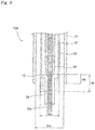
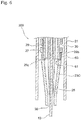
- Fig. 6 is an enlarged view of a main part of a welding torch according to a second configuration example in which a suction nozzle 23C has a heat-resistant insulating member 63 at a joining portion 61 with the tip body 29.
- a heat-resistant insulating member 63 having a melting point of 400°C or higher is disposed at the joining portion 61 between the tip body 29 supporting the contact tip 25 and the suction nozzle 23C.
- the temperature of a support portion of the suction nozzle 23C during welding has been confirmed to be elevated to about 350°C as measured using a thermocouple, and thus an allowance is given to the heating resistance temperature by ensuring that the melting point of the heat-resistant insulating member 63 is 400°C or higher.
- the welding torch 200 has the heat-resistant insulating member 63 having a melting point of 400°C or higher at the joining portion 61, and therefore sparking between the suction nozzle 23C and the workpiece can be prevented. In addition, deterioration of welding operability and the effect of reducing diffusible hydrogen due to contact between the welding wire and the suction nozzle during welding can be prevented.
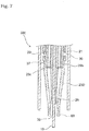
- Fig. 7 is an enlarged view of a main part of a welding torch according to a third configuration example in which the suction nozzle 23 has the heat-resistant insulating member 63 at a tip portion of a suction nozzle 23D.
- the suction nozzle 23D has the heat-resistant insulating member 63 having a melting point of 1700°C or higher at the tip portion of the suction nozzle 23 on the welded portion side.
- the welding torch 300 has the heat-resistant insulating member 63 having a melting point of 1700°C or higher at the tip portion of the suction nozzle 23D, and therefore sparking between the suction nozzle 23D and the workpiece can be prevented. In addition, deterioration of welding operability and the effect of reducing diffusible hydrogen due to contact between the welding wire and the suction nozzle during welding can be prevented. Since molten spatters at about 1500°C are deposited on the tip portion of the suction nozzle 23D, it is necessary to use a material having a melting point higher than that of the molten spatters for preventing damage to the nozzle. Thus, the melting point of the heat-resistant insulating member 63 is 1700°C or higher.
- Fig. 8 is an enlarged view of a main part of a welding torch according to a fourth configuration example in which the whole of the suction nozzle 23 is formed of a heat-resistant insulating material.
- the whole nozzle of a suction nozzle 23E is formed of a heat-resistant insulating material having a melting point of 1700°C or higher.
- the whole nozzle of the suction nozzle 23E is formed of a heat-resistant insulating material having a melting point of 1700°C or more, and therefore sparking between the suction nozzle 23E and the workpiece can be prevented without complicating formation of the suction nozzle 23E.
- deterioration of welding operability and the effect of reducing diffusible hydrogen due to contact between the welding wire and the suction nozzle during welding can be prevented.
- the welding torch 100 (the same applies to 100A, 100B, 200, 300, and 400) may have a configuration in which the suction nozzle 23 (hereinafter, the same applies to 23A, 23B, 23C, 23D, and 23E) and the shielding gas supply nozzle 21 having an oblong cross-section or an elliptical cross-section are concentrically disposed with the contact tip 25 at the center.
- the welding torch 100 may have a configuration in which the suction nozzle 23 and the shielding gas supply nozzle 21 having a tetragonal cross-section or a polygonal cross-section (e.g. a triangular, pentagonal, hexagonal or octagonal cross-section) are concentrically disposed with the contact tip 25 as the center.
- a tetragonal cross-section or a polygonal cross-section e.g. a triangular, pentagonal, hexagonal or octagonal cross-section
- the material of the suction nozzle 23 various metals such as Cu, Cu alloys, and steel can be used.
- the suction nozzle 23 may be plated with Cr or the like. However, since the suction nozzle 23 is disposed at a position where it is influenced by radiant heat from the arc 41, low-melting-point metals such as Al and Mg are not preferable.
- a ceramic As a material having a high electric resistance, a ceramic can be used.
- the ceramic include alumina, silicon nitride, and zirconia.
- welding quality can be improved by exhibiting high hydrogen suction performance while protecting the welding torch.
- a flux-containing wire A for 50 kgf-class steel was always used as a test welding wire.
- the diameter of the welding wire is ⁇ 1.2 mm.
- Welding conditions are shown below. Welding was automatic welding using a moving cart.
- Welding conditions are shown below. Welding was semiautomatic welding.
- grades A to D are passing grades, and grade E is a non-passing grade.
- the suction nozzle was evaluated in five grades: A to E, and the shielding gas supply nozzle and the insulating resin component were evaluated in three grades: A, C, and E. Of the grades of thereof, one closest to E was set to an overall grade in this test.
- Grades Classification based on JIS Z 3104 (1995), Annex 4 Criteria A Type 1, class 1 No defects B Type 1, class 1 Only flaws which have a flaw major diameter of 0.5 mm or less and which are not counted as flaws are found C Type 1, class 1 The flaw count is 1 D Type 1, class 2 (The flaw count is 2 or 3) E Type 1, class 3 or 4 (The flaw count is 4 or more)
- grades A to D are passing grades, and grade E is a non-passing grade.
- Experiment Example 6 in which the distance Ltk between the tip of the contact tip and the tip of the suction nozzle was 17 mm had low continuous weldability. However, this is because a large amount of spatters were deposited at the tip of the suction nozzle after continuous welding was performed for 10 minutes, and it was determined that further continuation of welding would clog the nozzle.
- Experiment Example 19 in which the distance Ltk was longer had a non-passing grade for continuous weldability.
- Experiment Example 1 in which the distance Ltk was 7 mm had good results for pore defects and the continuous welding test, but Experiment Example 18 in which the distance Ltk was shorter had a relatively high value as a diffusible hydrogen test result.
- Experiment Example 7 in which the distance Lts between the tip of the contact tip and the tip of the shielding gas supply nozzle was 0 mm had a low grade for pore defects.
- Experiment Example 11 in which the distance Lts was 18 mm had low continuous weldability.
- a large amount of spatters are deposited at the tip of the shielding gas supply nozzle just after performing the continuous welding, and the deposited spatters glowed. When the spatters were removed, there was no noticeable damage, but it was determined that further continuation of welding would damage the insulating member connecting the nozzle.
- Experiment Example 17 in which the distance Lts was longer had a non-passing grade in continuous weldability test.
- Experiment Example 12 in which the gap between the inner diameter Dsi of the shielding gas supply nozzle and the outer diameter Dko of the suction nozzle was small had a low grade for pore defects. It was determined that since the shielding gas flow had a small layer thickness of 2 mm, a slight amount of a nitrogen component was mixed in the arc atmosphere due to diffusion from the air. Further, Experiment Example 25 in which the gap between Dsi and Dko was as small as 1.5 mm had a low grade for pore defects.
- Experiment Examples 34 and 35 in which the flow velocity Vs at the shielding gas outlet was high had a low grade for pore defects.
- This flow rate is a value determined with a float-type flowmeter disposed in the middle of the suction shielding gas channel 17.
- hydrogen has a low density (light particles), and is therefore efficiently discharged when the shielding gas is a gas having a high density.
- the shielding gas is a gas having a low density, such as He, the discharge amount of hydrogen tends to relatively decrease.
Landscapes
- Engineering & Computer Science (AREA)
- Physics & Mathematics (AREA)
- Plasma & Fusion (AREA)
- Mechanical Engineering (AREA)
- Arc Welding In General (AREA)
Abstract
Description
- The present invention relates to a welding torch.
- In the welding industry, hydrogen embrittlement and hydrogen cracking of a weld metal by diffusible hydrogen (hydrogen atom H) in a weld metal poses a problem. Diffusible hydrogen in a weld metal gathers at grain boundaries and/or microspaces in a steel structure to form hydrogen molecules (H2), so that the volume is increased. The swelling pressure thereof causes cracking in the weld metal, leading to breakage of a construction. For such hydrogen cracking, susceptibility to hydrogen cracking becomes higher as the strength of steel increases, and in recent years, high-tensile-strength steel has tended to be used in welding.
-
Fig. 11 is a diagram for illustrating a process in which diffusible hydrogen is absorbed by a weld metal. InFig. 11 , a flux cored wire which is a welding wire containing a flux is used as a welding wire.Fig. 12 is a view showing a cross-section of the flux cored wire. - A
welding wire 201, which is a flux cored wire, includes asteel hoop 202 forming the outer periphery, and acentral portion 203. In the flux cored wire, thecentral portion 203 contains a metal powder of a metal or alloy, and a flux. Thewelding wire 201 is fed through acontact tip 208, and simultaneously, a welding current passes from thecontact tip 208 to thewelding wire 201, so that thewelding wire 201 is melted by anarc 209 at the tip of thewelding wire 201 to form aweld metal 210. Here, a welding current passes through awire protrusion portion 211 of thewelding wire 201, which is protruded from thecontact tip 208, and therefore resistance heat generation occurs, so that the temperature is elevated. For example, the elevated temperature reaches 100°C at a point about 5 mm away from the tip of thecontact tip 208, and may be elevated to about 600°C in the vicinity of a wire tip 20 mm away from the tip of thecontact tip 208. - When the temperature of the
wire protrusion portion 211 is elevated to a temperature above 100°C, first ahydrogen source 205 on the wire surface is vaporized, and discharged from thewelding wire 201. Subsequently, thecentral portion 203 is heated by conduction of heat from theheated steel hoop 202, thehydrogen source 205 in the flux and in the metal powder is also vaporized, and discharged to the outside of thewelding wire 201 through aseam 204 as a joint. A part of thehydrogen source 205 discharged from thewelding wire 201 flows in a direction indicated by anarrow 213 in accordance with an arc plasma stream, and a flow of a shielding gas supplied to a welded portion from a nozzle 206 (in a direction indicated by an arrow 207) in the case of gas shielding arc welding, and is guided to thearc 209. Since thearc 209 has a high temperature of several thousand degrees, thehydrogen source 205, e.g. H2O, is dissociated intodiffusible hydrogen 212, and absorbed by solution droplets in an arc column and theweld metal 210 to enter theweld metal 210. - In this way, the hydrogen source present on the wire surface and/or the hydrogen source contained in a flux and metal powder used for the welding wire are vaporized in the wire protrusion portion heated to a high temperature. The vaporized hydrogen source is carried to the inside of the arc column and the vicinity thereof by the arc plasma stream, and the flow of the shielding gas supplied in the case of gas shielding arc welding. The carried hydrogen source is dissociated into hydrogen atoms (i.e. diffusible hydrogen), and absorbed into the weld metal.
- As measures against hydrogen embrittlement and hydrogen cracking caused by diffusible hydrogen, preheating (heating of a weld steel material before welding) and/or post-heating (heating of a welded portion after welding) may be performed for promoting discharge of diffusible hydrogen to the outside from a weld metal. In addition, when a flux cored wire is used in welding, a method is also used in which fluorides such as CaF2 and/or Na3AlF6 are added to a flux to reduce diffusible hydrogen. Further, a method has also been proposed in which a very small amount of CF4 is mixed with a shielding gas supplied in gas shielding arc welding.
- Patent Document 1:
JP 2002-506736 A - Hydrogen sources in a welding wire include oil and moisture deposited on a wire surface, and moisture and organic substances deposited on a flux and metal powder included in a flux cored wire and/or a metal cored wire. Generally, the amount of the hydrogen source deposited on a flux and/or metal powder is larger than the amount of the hydrogen source deposited on a welding wire surface. Thus, for reduction of the hydrogen source that is deposited on a flux and metal powder, a method may be employed in which before production of a welding wire, the flux and metal particles are heated at a high temperature to remove the hydrogen source. In addition, prevention of absorption of moisture in a production process is necessary, but requires an enormous cost. Further, even after commercialization, moisture is adsorbed from air during storage and operation at a high-humidity welding site, and thus there are various obstacles to reduction of the hydrogen source.
- In addition, preheating and/or post-heating that is performed as measures against hydrogen embrittlement and hydrogen cracking involves heating at 150 to 250°C, and thus requires an enormous energy cost and labor. In addition, there is the problem that high-temperature operation is required, and thus a heavy burden is put on welding operators. When a fluoride is added to a flux, an increase in the amount of the additive deteriorates the stability of an arc, and therefore it may be unable to sufficiently reduce diffusible hydrogen. Further, the method in which CF4 is mixed with a shielding gas has a safety problem and a problem of deterioration of the stability of an arc, and there may be an obstacle to wide use of the method.
- The torch shown in Patent Document 1 sucks fumes from an opening portion that surrounds the periphery of a welding wire protruded from a contact tip, and faces a wire tip portion. It is thought that in this torch, a hydrogen source desorbed from the welding wire during welding is sucked together with fumes, and discharged to the outside of a welded portion to reduce the amount of diffusible hydrogen in a weld metal, although this is not described in Patent Document 1. However, Patent Document 1 shows only a rough configuration of the torch, and does not describe a detailed configuration including the sizes and relative positions of nozzles and tips. Considering the practicability and effectiveness of the system for reducing the amount of diffusible hydrogen, the torch may have an optimal configuration from the viewpoints of hydrogen suction performance, prevention of pore defects of a weld metal, and protection of torch components, but Patent Document 1 does not suggest such an optimal configuration. Since pursuit of hydrogen suction performance leads to a structure that cannot endure long-time use, a proper design is required. In addition, depending on the structure of a suction nozzle, the flow condition of a shielding gas is deteriorated, and therefore shielding property is deteriorated, so that air is entrained, leading to generation of pore defects. The present disclosure has been made in view of the above-described circumstances, and an object of the present disclosure is to provide a welding torch capable of improving welding quality by exhibiting high hydrogen suction performance while protecting the welding torch.
- An example of the present invention provides a welding torch which performs arc welding in a shielding gas atmosphere, the welding torch comprising: a contact tip that supports a welding wire which is supplied with a welding current while the welding wire can be fed toward a tip portion; a suction nozzle that surrounds a periphery of the welding wire protruded from a tip portion of the contact tip, and sucks a gas from a space formed between the suction nozzle and the welding wire; and a shielding gas supply nozzle that is provided on an outer periphery of the suction nozzle, and supplies the shielding gas toward a welded portion at a tip of the welding wire from a space formed between the shielding gas supply nozzle and the suction nozzle, wherein where Lts [mm] is a distance along a welding wire longitudinal direction between a tip of the contact tip and a tip of the shielding gas supply nozzle, and Ltk [mm] is a distance along the welding wire longitudinal direction between the tip of the contact tip and a tip of the suction nozzle, the welding torch satisfies the relationship of the formula (1).

- According to the present disclosure, welding quality can be improved by exhibiting high hydrogen suction performance to prevent generation of pore defects etc. of a weld metal while protecting a welding torch.
-
-
Fig. 1 is a diagram showing one example of a schematic configuration of a welding apparatus according to an embodiment; -
Fig. 2 is a sectional view taken along line A-A inFig. 1 ; -
Fig. 3 is an enlarged view of a main part of a tip portion of the welding torch shown inFig. 1 ; -
Fig. 4 is an enlarged view of a main part of a welding torch according to a modification in which a suction nozzle has a taper; -
Fig. 5 is an enlarged view of a main part of a welding torch according to a modification in which the shape of the tip portion of the suction nozzle is changed; -
Fig. 6 is an enlarged view of a main part of a welding torch according to a second configuration example in which a suction nozzle has a heat-resistant insulating member at a joining portion with a tip body; -
Fig. 7 is an enlarged view of a main part of a welding torch according to a third configuration example in which a suction nozzle has a heat-resistant insulating member at a tip portion of the suction nozzle; -
Fig. 8 is an enlarged view of a main part of a welding torch according to a fourth configuration example in which the whole of a suction nozzle is formed of a heat-resistant insulating material; -
Fig. 9 is a sectional view of a test plate used in a test of pore defects; -
Fig. 10 is a plan view of the test plate shown inFig. 9 ; -
Fig. 11 is a diagram for illustrating a process in which diffusible hydrogen is absorbed by a weld metal; and -
Fig. 12 is a view showing a cross-section of a flux cored wire. - Hereinafter, an embodiment of the present invention will be described with reference to the drawings.
- A
welding apparatus 10 according to a configuration example is an apparatus that performs welding by consumable electrode type gas shielding arc welding. The consumable electrode is an electrode that is melted by arc heat in arc welding. In addition, the gas shielding arc welding is a welding method in which welding is performed with a welded portion shielded from outside air by an injected shielding gas. Thewelding apparatus 10 performs welding while sucking a shielding gas containing ahydrogen source 11 in the vicinity of the wire protrusion portion in the shielding gas injected to the welded portion. -
Fig. 1 is a diagram showing one example of a schematic configuration of thewelding apparatus 10 according to an embodiment. As shown inFig. 1 , thewelding apparatus 10 of this configuration example includes awelding torch 100 that welds a workpiece W using awelding wire 13; and asuction apparatus 15 that sucks a shielding gas. In addition, thewelding apparatus 10 includes a suction shieldinggas channel 17 connecting thewelding torch 100 and thesuction apparatus 15. - The
welding torch 100 welds the workpiece W by feeding awelding wire 13 with a welding current supplied from a welding power source (not shown). As thewelding wire 13, for example, a flux cored wire having a metal powder and a flux at a central portion, a metal cored wire having mainly a metal powder at a center portion, or a solid wire composed of an alloy such as steel is used. - The
welding torch 100 includes a shieldinggas supply nozzle 21, asuction nozzle 23, acontact tip 25, asuction channel 27, and atip body 29. Further, an insulatingcomponent 28 for insulating the shieldinggas supply nozzle 21 and thetip body 29 is provided between the shieldinggas supply nozzle 21 and thetip body 29. - The
suction apparatus 15 includes a flowrate control valve 31 and anejector 33, and sucks a shielding gas from thesuction nozzle 23 of thewelding torch 100. The shielding gas is supplied to the shieldinggas supply nozzle 21 from an external shielding gas supply apparatus (not shown) such as a shielding gas cylinder. It suffices that thesuction apparatus 15 has a suction capacity of, for example, about 25L/min. It is possible to employ a suction apparatus which is small in size and available at a low cost rather than one requiring a large amount of energy. - The suction shielding
gas channel 17 connects thesuction channel 27 of thewelding torch 100 to thesuction apparatus 15 to form a channel through which the sucked shielding gas flows. The suction shieldinggas channel 17 is formed of, for example, a rubber tube. - Next, a configuration of the
welding torch 100 will be described. - The shielding
gas supply nozzle 21 has a tubular shape, and is fitted and fixed to the tubularly formedtip body 29 from the lower side inFig. 1 . The insulatingresin component 28 is provided on an outerperipheral surface 29a of thetip body 29 on the upper side in the drawing, so that the shieldinggas supply nozzle 21 and thetip body 29 are insulated from each other. The shieldinggas supply nozzle 21 supplies a shielding gas to the welded portion. In addition, since the shieldinggas supply nozzle 21 is tubularly formed, the shielding gas is supplied in such a manner that the welded portion is surrounded and shielded from outside air. - The
suction nozzle 23 is disposed in the shieldinggas supply nozzle 21, and has a tubular shape. Thesuction nozzle 23 is fitted and fixed to the outerperipheral surface 29b of the tubular portion of thetip body 29, which is protruded to the lower side inFig. 1 . Anorifice 30 serving as a throttle for making uniform the shielding gas sent from a shielding gas supply apparatus (not shown) is disposed between the shieldinggas supply nozzle 21 and the outerperipheral surface 29b of thetip body 29 connected to thesuction nozzle 23. - The
suction nozzle 23 is structured to surround the periphery of awire protrusion portion 37 of thewelding wire 13, which is protruded from thecontact tip 25, and thesuction nozzle 23 has an openingportion 39 extending toward the tip portion of thewelding wire 13.Fig. 2 is a sectional view taken along line A-A inFig. 1 in thewelding apparatus 10. As shown inFig. 2 , awelding wire 13 is provided at the center of thecontact tip 25, and thesuction nozzle 23 exists so as to surround the periphery of thecontact tip 25. In addition, the shieldinggas supply nozzle 21 is provided so as to surround the periphery of thesuction nozzle 23. - Here, the
suction nozzle 23 is opened toward the tip of thewelding wire 13, i.e. along a direction in which anarc 41 is generated. The suction nozzle is configured to suck a shielding gas including thehydrogen source 11 discharged in the vicinity of the wire tip portion. When sucked by thesuction nozzle 23, the shielding gas including thehydrogen source 11 is discharged to the outside of the welded portion by flowing in a direction ofarrow 43, which is a direction in which the shielding gas goes toward the outside of the welded portion. - For sucking the
hydrogen source 11 discharged in the vicinity of the wire tip portion, thesuction nozzle 23 may be configured to have such a large length that even the wire tip portion is surrounded, but there is the possibility that thesuction nozzle 23 is melted by arc heat. Thus, thesuction nozzle 23 is configured to be opened toward the wire tip portion while having a length determined with consideration given to influences of arc heat. As thesuction nozzle 23, for example, a copper alloy excellent in heat conduction, or a ceramic excellent in heat resistance is used. Further, one subjected to chromium plating or the like for preventing deposition of spatters may be used. - The
contact tip 25 is disposed on an inner diameter portion of thesuction nozzle 23, and has a tubular shape. Thecontact tip 25 is fixed by fitting a contact tip upper portion to aninner diameter portion 29c of thetip body 29 on the lower side inFig. 1 . Thecontact tip 25 guides thewelding wire 13, and supplies a welding current to thewelding wire 13. In thecontact tip 25, a wire feeding channel having a diameter that allows the wire feeding channel to come into contact with thewelding wire 13 is formed, and power is supplied to thewelding wire 13. In addition, thecontact tip 25 is detachably attached to thetip body 29, and is replaced when worn due to long-time use. - The
suction channel 27 guides the shielding gas sucked by thesuction nozzle 23 to thesuction apparatus 15. Thissuction channel 27 includes passages formed by boring four holes with a diameter of, for example, about 1.5 mm in thetip body 29 using a drill, and the passages formed by the four holes are joined in acircumferential joining groove 45, and then connected to thesuction apparatus 15 through the suction shieldinggas channel 17. However, thesuction channel 27 does not necessarily have such a configuration, and may have any configuration as long as it forms a channel that guides the shielding gas and/orhydrogen source 11 from thesuction nozzle 23 to thesuction apparatus 15. - The
tip body 29 is a main body portion of thewelding torch 100. Thetip body 29 has a tubular shape, and supports the shieldinggas supply nozzle 21, thesuction nozzle 23, and thecontact tip 25 which are connected through the insulatingresin component 28. - Next, a configuration of the
suction apparatus 15 will be described. - The flow
rate control valve 31 is formed by, for example, a needle valve, includes an actuator such as a motor (not shown), and controls a suction flow rate. The flowrate control valve 31 is provided between asuction port 47 of theejector 33 as described later and the suction shieldinggas channel 17. - The
ejector 33 is in the form of a T-shaped tube, and has a function of a general ejector. That is, when a drive gas such as compressed air flows in a horizontal direction, the flow velocity is increased at a portion having a small diameter in the tube, and a tube corresponding to the vertical line of the T shape serves as a suction port, so that a shielding gas is sucked through thesuction nozzle 23. Theejector 33 includes adrive nozzle 52, agas supply port 51, asuction port 47, and anexhaust port 35. - In the
ejector 33, a drive gas such as compressed air is supplied to thegas supply port 51. In addition, the drive gas guided from thegas supply port 51 to thedrive nozzle 52 is ejected toward theexhaust port 35. Here, a suction force acts on thesuction port 47, and the shielding gas including thehydrogen source 11 is guided to thesuction port 47 from thesuction nozzle 23 connected through the suction shieldinggas channel 17 and thesuction channel 27. The sucked shielding gas including thehydrogen source 11 in thesuction port 47 is sent to theexhaust port 35. - Thus, in the
welding apparatus 10 according to this configuration example, thesuction apparatus 15 performs suction on the periphery of thewire protrusion portion 37 and in the vicinity of the tip portion of thewelding wire 13 by thesuction nozzle 23. The shielding gas including thehydrogen source 11 discharged from theheated welding wire 13 flows in a direction ofarrow 43, which is a direction in which the shielding gas goes toward the outside of the welded portion and is sucked. When suction is not performed using thesuction apparatus 15, thehydrogen source 11 is situated just above thearc 41, and therefore most of thehydrogen source 11 is guided to thearc 41, and absorbed into the weld metal. On the other hand, by using thewelding apparatus 10 according to this configuration example, a situation in which thehydrogen source 11 flows into thearc 41, and is absorbed into the weld metal as diffusible hydrogen in thearc 41 is suppressed to reduce the amount of diffusible hydrogen in the weld metal. As a result of reducing the amount of diffusible hydrogen in the weld metal, hydrogen embrittlement and hydrogen cracking in the weld metal are prevented. - Generally, the required preheating temperature can be lowered by about 25°C by decreasing the amount of diffusible hydrogen in a weld metal by 1 mL/100 g. For example, when the amount of diffusible hydrogen is decreased by 4 mL/100 g, the preheating temperature can be lowered by 100°C in welding requiring a preheating temperature of 125°C, so that the preheating temperature is lowered to 25°C, resulting in elimination of necessity of preheating. In addition, for example, in welding requiring a preheating temperature of 200°C, the preheating temperature is 100°C or lower. The lowering of the preheating temperature provides economic effects such as saving of preheating energy and/or reduction of labor and time required for preheating. In addition, a harsh work environment for preheating operation at 200°C is improved.
- Further, the
welding wire 13 absorbs moisture depending on the storage environment, but whether thewelding wire 13 absorbs moisture is not known by visual observation, and therefore thorough management of the storage environment is required. When thewelding apparatus 10 according to this configuration example is used, the amount of diffusible hydrogen in the weld metal decreases, and therefore the level of management of the storage environment is reduced, so that even if absorption of moisture occurs due to a human mistake, influences of such a mistake are relaxed. -
Fig. 3 is an enlarged view of a main part of the tip portion of the welding torch shown inFig. 1 . - The
welding torch 100 of this configuration example performs arc welding in a shielding gas atmosphere. The welding torch includes: thecontact tip 25 that supports a welding wire which is supplied with a welding current while the welding wire can be fed toward a tip portion; thesuction nozzle 23 that surrounds a periphery of the welding wire protruded from a tip portion of thecontact tip 25, and sucks a gas from a space formed between thesuction nozzle 23 and the welding wire; and the shieldinggas supply nozzle 21 that is provided on an outer periphery of thesuction nozzle 23, and supplies the shielding gas toward a welded portion at a tip of the welding wire from a space formed between the shieldinggas supply nozzle 21 and thesuction nozzle 23. - Here, the
contact tip 25, the shieldinggas supply nozzle 21, and thesuction nozzle 23 in thewelding torch 100 has the following positional relationship. - That is, where Lts [mm] is a distance along a welding wire longitudinal direction between the tip of the
contact tip 25 and the tip of the shieldinggas supply nozzle 21, and Ltk [mm] is a distance along the welding wire longitudinal direction between the tip of thecontact tip 25 and the tip of thesuction nozzle 23, thewelding torch 100 satisfies the relationship of the formula (1).
- The distance Ltk is preferably 9 or more, and preferably 15 or less, more preferably 14 or less.
- In addition, the distance Lts is preferably 4 or more, and preferably 16 or less, more preferably 15 or less.
- In addition, the
welding torch 100 satisfies the relationship of the following formula regarding the diameters of the shieldinggas supply nozzle 21 and thesuction nozzle 23. - That is, where Dsi [mm] is an inner diameter of the shielding
gas supply nozzle 21, Dki [mm] is an inner diameter of thesuction nozzle 23, and Dko [mm] is an outer diameter of thesuction nozzle 23, thewelding torch 100 satisfies the relationship of the formula (2).
- The difference Dsi-Dko between the inner diameter Dsi of the shielding
gas supply nozzle 21 and the outer diameter Dko of thesuction nozzle 23 is preferably 3 or more. In addition, the difference Dko-Dki is preferably 2 or more. - In addition, the inner diameter Dsi of the shielding
gas supply nozzle 21 is preferably 13 or more, and more preferably 35 or less. - In addition, the inner diameter Dki of the
suction nozzle 23 is preferably 1.8 or more, and more preferably 8 or less. - However, when a plurality of
suction nozzles 23 are mounted, the largest of the distances along the welding wire longitudinal direction between the tip of thecontact tip 25 and the tips of thesuction nozzles 23 is defined as the distance Ltk. - In addition, the
welding torch 100 has an electric resistance of 50 Ω or more between thetip body 29 and the tip of thesuction nozzle 23. The electric resistance is more preferably 500 Ω or more. - In addition, the surface roughness of the inner surface of the suction nozzle in the
welding torch 100 satisfies the relationship of following formula. - That is, where Ra [µm] is an arithmetic mean roughness of the inner surface of the suction nozzle, the surface roughness Ra of the nozzle inner peripheral surface in the
suction nozzle 23 of thewelding torch 100 satisfies the relationship of 0.05 ≤ Ra ≤ 50. - The arithmetic mean roughness Ra is preferably 20 or less, more preferably 10 or less. In addition, the arithmetic mean roughness Ra is preferably 0.3 or more, more preferably 1 or more.
- In addition, where Qk [L/min] is a suction gas flow rate at the
suction nozzle 23, thewelding torch 100 satisfies the relationship of the following formula (3).
- The distance Ltk is preferably 10 - 0.4 × Qk or more.
- In addition, where Ss [mm2] is a cross-sectional area of a shielding gas outlet at the tip of the shielding
gas supply nozzle 21, Qs [L/min] is a shielding gas flow rate, and Vs [m/s] is a flow velocity at the shielding gas outlet, thewelding torch 100 satisfies the relationship of the formula (4).
- The flow velocity Vs is preferably 5 or less, more preferably 4 or less.
-
Fig. 4 is an enlarged view of a main part of a welding torch according to a modification in which thesuction nozzle 23 has a taper. In awelding torch 100A of this modification, asuction nozzle 23A is formed so as to have a taper in which the diameter gradually decreases as going toward the tip. Since thesuction nozzle 23A has a taper, the flow velocity at thesuction channel 27 can be gradually increased as going toward the tip opening. In addition, in thewelding torch 100A, a space formed between the outer periphery of thesuction nozzle 23A and the shieldinggas supply nozzle 21 can be expanded by forming thesuction nozzle 23A with a taper. Accordingly, the flow velocity Vs at the shielding gas outlet can be easily set within a preferred range. -
Fig. 5 is an enlarged view of a main part of a welding torch according to a modification in which the shape of the tip portion of asuction nozzle 23B is changed. - In a
welding torch 100B of this modification, the outerperipheral surface 29b of thetip body 29 supports thesuction nozzle 23B, and theinner diameter portion 29c of thetip body 29 supports thecontact tip 25. - In the examples shown in
Figs. 3 and4 , the inner surface of the tip portion of each of thesuction nozzles suction nozzle 23B shown inFig. 5 . - Next, effects of the above-described configuration will be described.
- The
welding torch 100 sucks a part of the shielding gas for reducing the amount of diffusible hydrogen in the weld metal. Here, matters to be noted include hydrogen suction performance, prevention of generation of pore defects in the weld metal, and protection of torch components. - During welding, the
welding wire 13 delivered from thecontact tip 25 is fed with a welding current from this moment, and therefore undergoes generation of Joule heat, so that the temperature is elevated. The temperature is elevated as the distance between thewelding wire 13 and thecontact tip 25 increases. In addition, the discharge rate of thehydrogen source 11 discharged from thewelding wire 13 increases as the amount of applied energy increases. Thus, when consideration is given to hydrogen suction performance, it is preferable that the suction nozzle 23 (the same applies to referencenumerals welding wire 13 up to a position at which the wire temperature is further elevated. That is, in thesuction nozzle 23, the distance Ltk along the welding wire longitudinal direction between the tip of thecontact tip 25 and the tip of thesuction nozzle 23 is preferably long. - When the suction flow rate Qk is large, the
hydrogen source 11 discharged at a position distant from thesuction nozzle 23 by a flow at the tip of the nozzle can also be sucked. In this connection, the inventors have derived a relational formula between the preferred suction flow rate and the suction nozzle position (see the foregoing formula (3)) through an experiment. - When welding is performed for a long time using the
suction nozzle 23, fumes are easily stacked if the surface roughness of the inner surface of thesuction nozzle 23 is excessively large. When fumes are stacked, clogging occurs between thecontact tip 25 and the suction nozzle, so that a gas cannot be sucked. For preventing such deposition of fumes, the surface roughness of the inner surface of the suction nozzle in the welding torch 100 (the same applies to 100A and 100B) is preferably small. - In a welding method using the
welding torch 100, a part of a shielding gas is sucked, and therefore the shielding property of the welded portion is deteriorated as compared to general gas shielding arc welding. When the shielding property is deteriorated, there arise problems of generation of pore defects in the weld metal, and so on. For preventing deterioration of the shielding property, the positions of the shield nozzle tip and the workpiece W are preferably close to each other. On the other hand, it is preferable that at the time of carrying out a welding procedure, the distance between thecontact tip 25 and the workpiece W is adjusted to about 20 to 30 mm from the viewpoint of welding operability. When relative positional relation between the tip of the contact tip and the tip of the shielding gas supply nozzle (distance Lts along the welding wire longitudinal direction between the tip of the contact tip and the tip of the shielding gas supply nozzle) is set within a predetermined range in light of practical use, high shielding property can be secured in thewelding torch 100. - In addition, when the
suction nozzle 23 is made of a conductive material, and is not insulated from thetip body 29, the tip of the suction nozzle has a potential equal to that of thewelding wire 13. Thus, when thesuction nozzle 23 and the workpiece inadvertently come into contact with each other at the time of, for example, performing semiautomatic welding, sparking may occur between the suction nozzle and the workpiece, resulting in erosion of thesuction nozzle 23. However, with thewelding torch 100 having this configuration, erosion due to inadvertent sparking can be prevented because the shield nozzle is long, and thesuction nozzle 23 is substantially covered. - Further, when the outer diameter of the
suction nozzle 23 and the inner diameter of the shieldinggas supply nozzle 21 are small, the layer thickness of the gas which secures shielding property decreases, so that ingress of outside air into the inner part easily occurs. Exactly speaking, the flow velocity and the flow rate of the shielding gas may be related to securement of shielding property, and it has been confirmed that when the difference between the inner diameter Dsi of the shieldinggas supply nozzle 21 and the outer diameter Dko of thesuction nozzle 23 is set within a predetermined range under the supply of the shielding gas at an appropriate flow rate, shielding property is improved. - It is preferable that the shielding gas is sent in a laminar flow state with little involvement of an ambient gas. However, when the outer diameter of the
suction nozzle 23 is thick and/or the shieldinggas supply nozzle 21 is thin, the shielding gas flow velocity at the outlet of the shieldinggas supply nozzle 21 increases, so that the shielding gas is brought into a turbulent flow state even when the shielding gas is supplied at an appropriate flow rate. Here, air is excessively involved. For preventing such involvement of an ambient gas, the approximate value of the flow velocity at the gas outlet of the shieldinggas supply nozzle 21 in thewelding torch 100 is preferably low. - In securement of hydrogen suction performance as described above, the distance Ltk is preferably long, and on the other hand, the distance between the workpiece W and the
suction nozzle 23 is preferably long for preventing thesuction nozzle 23 from being damaged by spatters and/or radiant heat from thearc 41. For the distance between thecontact tip 25 and the workpiece W, there is a proper range in view of welding operability. Thus, in thewelding torch 100, it is necessary to decrease the distance Ltk for protecting thesuction nozzle 23. - In securement of shielding property and protection of sparking of suction nozzle as described above, the distance Lts is preferably long, and on the other hand, the distance between the workpiece W and the shielding
gas supply nozzle 21 is long for preventing the shieldinggas supply nozzle 21 from being overheated by radiant heat from thearc 41 to burn the insulatingresin component 28 on the periphery of the tip body. For the distance between thecontact tip 25 and the workpiece W, there is a proper range in view of welding operability. Thus, in thewelding torch 100, it is necessary to decrease the distance Lts for protection of thesuction nozzle 23. - The
suction nozzle 23 receives intense radiant heat from thearc 41. Thesuction nozzle 23 is normally cooled by a shielding gas flow, and therefore is not damaged, but when the thickness of the nozzle tip portion is small, the suction nozzle has a low heat capacity and poor heat conduction. Thus, the nozzle tip portion may be melted. For preventing erosion of thesuction nozzle 23, it is necessary to increase the thickness (Dko-Dki) of the tip portion. - When the
suction nozzle 23 is composed of a conductive material, thesuction nozzle 23 has a potential equal to thetip body 29 and/or thecontact tip 25. Thus, when the workpiece W and thesuction nozzle 23 are inadvertently brought into contact with each other, anarc 41 is generated from thesuction nozzle 23, so that thesuction nozzle 23 is immediately eroded. For preventing such erosion, it is preferable to increase the electric resistance between thetip body 29 and the tip of the suction nozzle. In addition, thewelding wire 13 has a certain curve (cast) depending on the product form thereof. When the cast causes thewelding wire 13 and the tip of the suction nozzle to come into contact with each other, an unstable branch current passes by way of thesuction nozzle 23. The unstable branch current deteriorates welding operability, and reduces the amount of heat generated by the wire at a portion covered with thesuction nozzle 23. In addition, the effect of reducing diffusible hydrogen may also be deteriorated because the discharge amount of thehydrogen source 11 decreases. - The electric resistance of the
welding wire 13 which is a good conductor is very low. The electric resistance is about 20 mΩ at an interval of about 25 mm between the contact tip and the base material. Thus, for preventing generation of an arc from thesuction nozzle 23 and/or passage of a large branch current through the suction nozzle due to contact between thewelding wire 13 and the tip of the suction nozzle, the electric resistance between the tip body and the tip of the suction nozzle may be set to 50 Ω or more. For designing thewelding torch 100 with higher safety, it is preferable to set the electric resistance between the tip body and tip of the suction nozzle to 500 Ω or more. - In the
welding torch 100 with this configuration, the distance Lts along the welding wire longitudinal direction between the tip of thecontact tip 25 and the tip of the shieldinggas supply nozzle 21, and the distance Ltk along the welding wire longitudinal direction between the tip of thecontact tip 25 and the tip of thesuction nozzle 23 satisfy the relationship of:
suction nozzle 23, secure shielding property and prevent sparking of the suction nozzle, and protect torch durability and the insulating resin. - In addition, in the
welding torch 100, the tips of the shieldinggas supply nozzle 21 and thesuction nozzle 23 satisfy the relationship of:


suction nozzle 23. - In addition, the
welding torch 100 has an electric resistance of 50 Ω or more between thetip body 29 and the tip of thesuction nozzle 23, and therefore sparking of thesuction nozzle 23 can be prevented. - In addition, in the
welding torch 100, the surface roughness Ra of the nozzle inner peripheral surface of thesuction nozzle 23 is 0.05 µm or more and 50 µm or less, and therefore fumes are hardly deposited or stacked on the nozzle inner peripheral surface, and thus clogging of thesuction nozzle 23 in long-time use can be prevented. - In addition, where Qk is a suction gas flow rate at the
suction nozzle 23, thewelding torch 100 satisfies the relationship of:
- Further, where Ss is a cross-sectional area of a shielding gas outlet at the tip of the shielding
gas supply nozzle 21, Qs is a shielding gas flow rate, and Vs is a flow velocity at the shielding gas outlet, thewelding torch 100 satisfies the relationship of:

- Next, other configuration examples of the welding torch will be described.
-
Fig. 6 is an enlarged view of a main part of a welding torch according to a second configuration example in which asuction nozzle 23C has a heat-resistant insulatingmember 63 at a joiningportion 61 with thetip body 29. - In a
welding torch 200 with this configuration, a heat-resistant insulatingmember 63 having a melting point of 400°C or higher is disposed at the joiningportion 61 between thetip body 29 supporting thecontact tip 25 and thesuction nozzle 23C. The temperature of a support portion of thesuction nozzle 23C during welding has been confirmed to be elevated to about 350°C as measured using a thermocouple, and thus an allowance is given to the heating resistance temperature by ensuring that the melting point of the heat-resistant insulatingmember 63 is 400°C or higher. - The
welding torch 200 has the heat-resistant insulatingmember 63 having a melting point of 400°C or higher at the joiningportion 61, and therefore sparking between thesuction nozzle 23C and the workpiece can be prevented. In addition, deterioration of welding operability and the effect of reducing diffusible hydrogen due to contact between the welding wire and the suction nozzle during welding can be prevented. -
Fig. 7 is an enlarged view of a main part of a welding torch according to a third configuration example in which thesuction nozzle 23 has the heat-resistant insulatingmember 63 at a tip portion of asuction nozzle 23D. - In a
welding torch 300 with this configuration, thesuction nozzle 23D has the heat-resistant insulatingmember 63 having a melting point of 1700°C or higher at the tip portion of thesuction nozzle 23 on the welded portion side. - The
welding torch 300 has the heat-resistant insulatingmember 63 having a melting point of 1700°C or higher at the tip portion of thesuction nozzle 23D, and therefore sparking between thesuction nozzle 23D and the workpiece can be prevented. In addition, deterioration of welding operability and the effect of reducing diffusible hydrogen due to contact between the welding wire and the suction nozzle during welding can be prevented. Since molten spatters at about 1500°C are deposited on the tip portion of thesuction nozzle 23D, it is necessary to use a material having a melting point higher than that of the molten spatters for preventing damage to the nozzle. Thus, the melting point of the heat-resistant insulatingmember 63 is 1700°C or higher. -
Fig. 8 is an enlarged view of a main part of a welding torch according to a fourth configuration example in which the whole of thesuction nozzle 23 is formed of a heat-resistant insulating material. - In a
welding torch 400 with this configuration, the whole nozzle of asuction nozzle 23E is formed of a heat-resistant insulating material having a melting point of 1700°C or higher. - In the
welding torch 400, the whole nozzle of thesuction nozzle 23E is formed of a heat-resistant insulating material having a melting point of 1700°C or more, and therefore sparking between thesuction nozzle 23E and the workpiece can be prevented without complicating formation of thesuction nozzle 23E. In addition, deterioration of welding operability and the effect of reducing diffusible hydrogen due to contact between the welding wire and the suction nozzle during welding can be prevented. - In addition, the welding torch 100 (the same applies to 100A, 100B, 200, 300, and 400) may have a configuration in which the suction nozzle 23 (hereinafter, the same applies to 23A, 23B, 23C, 23D, and 23E) and the shielding
gas supply nozzle 21 having an oblong cross-section or an elliptical cross-section are concentrically disposed with thecontact tip 25 at the center. - Further, the
welding torch 100 may have a configuration in which thesuction nozzle 23 and the shieldinggas supply nozzle 21 having a tetragonal cross-section or a polygonal cross-section (e.g. a triangular, pentagonal, hexagonal or octagonal cross-section) are concentrically disposed with thecontact tip 25 as the center. - As the material of the
suction nozzle 23, various metals such as Cu, Cu alloys, and steel can be used. Thesuction nozzle 23 may be plated with Cr or the like. However, since thesuction nozzle 23 is disposed at a position where it is influenced by radiant heat from thearc 41, low-melting-point metals such as Al and Mg are not preferable. - As a material having a high electric resistance, a ceramic can be used. Examples of the ceramic include alumina, silicon nitride, and zirconia.
- Therefore, with the
welding torch 100 according to this configuration example, welding quality can be improved by exhibiting high hydrogen suction performance while protecting the welding torch. - A flux-containing wire A for 50 kgf-class steel was always used as a test welding wire. The diameter of the welding wire is ϕ1.2 mm.
- Results obtained in accordance with "JIS Z 3118 (2007), Method for Measurement of Amount of Hydrogen in Steel Welded Portion" were determined from the equation shown in "JIS Z 3118 (2007), Article 7.2, Calculation of Amount of Hydrogen per Mass of Weld Metal," and an average value for three trials was employed as a result value.
- Welding conditions are shown below. Welding was automatic welding using a moving cart.
- Polarity: DCEP Welding current: 270A
- Arc voltage: 32V
- Welding speed: 350mm/min
- Contact tip-base material distance: 25mm
- Welding position: downward
- When there was a sufficiently significant difference (difference of 3 mL/100 ml or more) in test result (experiment example 20 in Table 4) between the present welding torch and a nozzle-free torch for sucking hydrogen, it was determined that the present torch was effective (acceptable when the amount was 5.1 mL/100 ml or less).
- For a test plate obtained by subjecting a base material with groove dimensions as shown in
Figs. 9 and 10 to one-pass welding, a radiograph was taken in accordance with "JIS Z 3104 (1995), Method for Radiation Transmission Test of Steel Welded Joint". Table 1 shows results of classifying the obtained radiograph in accordance with "JIS Z 3104 (1995), Annex 4, Method for Classification of Flaw Images in Radiography, and unique criteria. In this test, flaws of type 2, type 3, and type 4 were not found, and only flaws of type 1 were found. - Welding conditions are shown below. Welding was semiautomatic welding.
- Polarity: DCEP Welding current: 270A
- Arc voltage: 32V
- Welding speed: 270 - 300mm/min
- Contact tip-base material distance: 25mm
- Welding position: downward
- Material of base material: SM 490A (rolled steel material for welded structure JIS G 3106) Dimensions of base material: Length L1 = 200 mm, width L2 = 150 mm, thickness ta = 6 mm
- Groove angle α = 45°
- Base material distance d = 4 mm
- Backing metal: thickness tb = 6 mm
- In the table, grades A to D are passing grades, and grade E is a non-passing grade.
- Continuous welding was performed for 10 minutes to examine the durability of the torch and the nozzle. After completion of the welding, each component was observed and evaluated for damage. In evaluation of the suction nozzle and the shielding gas supply nozzle, deposited spatters were removed, and these nozzles were evaluated from the deposition thickness and the surface condition after the removal. Evaluation criteria are shown in Table 2.
- The suction nozzle was evaluated in five grades: A to E, and the shielding gas supply nozzle and the insulating resin component were evaluated in three grades: A, C, and E. Of the grades of thereof, one closest to E was set to an overall grade in this test.
[Table 2] Grades Classification based on JIS Z 3104 (1995), Annex 4 Criteria A Type 1, class 1 No defects B Type 1, class 1 Only flaws which have a flaw major diameter of 0.5 mm or less and which are not counted as flaws are found C Type 1, class 1 The flaw count is 1 D Type 1, class 2 (The flaw count is 2 or 3) E Type 1, class 3 or 4 (The flaw count is 4 or more) - In the table, grades A to D are passing grades, and grade E is a non-passing grade.
- Gas density [kg/m3] (0°C 1 atm [101 kPa])
[Table 3] H2 CO2 Ar He 0.0899 1.977 1.783 0.1786 -
[Table 4] No. Lts Ltk Dsi Dki Dko Dsi-Dko Dko-Dki Suction flow rate Qk [l/min] 10-0.6 × Qk 10-0.4 × Qk Gas flow rate Qs [l/min] Cross-sectional shielding gas outlet [mm2] Flow rate Vs at shielding gas port [m/s] Roughness of inner surface of suction nozzle [µm] Shielding gas Diffusible hydrogen test result Pore of weld metal Continuous welding test Experiment Example 1 10 7 13 4 6 7 2 8 5.2 6.8 25 104 4.0 Lathe machining: About 2 µm CO2 3.3 A A Experiment Example 2 10 9 13 4 6 7 2 8 5.2 6.8 25 104 4.0 Lathe machining: About 2 µm CO2 2.8 A B Experiment Example 3 10 12 16 4 8 8 4 8 5.2 6.8 25 151 2.8 Lathe machining: About 2 µm CO2 2.3 A A Experiment Example 4 10 14 16 4 8 8 4 8 5.2 6.8 25 151 2.8 Lathe machining: About 2 µm CO2 2.6 A A Experiment Example 5 10 15 16 4 8 8 4 8 5.2 6.8 25 151 2.8 Lathe machining: About 2 µm CO2 2.5 A C Experiment Example 6 10 17 16 4 8 8 4 8 5.2 6.8 25 151 2.8 Lathe machining: About 2 µm CO2 2.7 A D Experiment Example 7 0 9 19 5 8 11 3 8 5.2 6.8 25 233 1.8 Lathe machining: About 2 µm CO2 3.1 D A Experiment Example 8 4 9 19 5 8 11 3 8 5.2 6.8 25 233 1.8 Lathe machining: CO2 3.1 A A Experiment Example 9 15 9 19 5 8 11 3 8 5.2 6.8 25 233 1.8 Lathe machining: About 2 µm CO2 2.8 A A Experiment Example 10 16 9 19 5 8 11 3 8 5.2 6.8 25 233 1.8 Lathe machining: About 2 µm CO2 3.0 A A Experiment Example 11 18 9 19 5 8 11 3 8 5.2 6.8 25 233 1.8 Lathe machining: About 2 µm CO2 3.2 A D Experiment Example 12 10 9 16 5 14 2 9 8 5.2 6.8 15 47 5.3 Lathe machining: About 2 µm CO2 2.9 D A Experiment Example 13 10 9 16 5 13 3 8 8 5.2 6.8 15 68 3.7 Lathe machining: About 2 µm CO2 3.0 C A Experiment Example 14 10 9 16 5 11 5 6 8 5.2 6.8 20 106 3.1 Lathe machining About 2 µm CO2 3.1 B A Experiment Example 15 10 9 16 1.8 3 13 1.2 8 5.2 6.8 25 194 2.1 Lathe machining: About 2 µm CO2 2.4 A C Experiment Example 16 -3 9 16 5 10 6 5 8 5.2 6.8 25 123 3.4 Lathe machining: About 2 µm CO2 3.1 E A Experiment Example 17 20 9 16 5 10 6 5 8 5.2 6.8 25 123 3.4 Lathe machining: About 2 µm CO2 2.9 A E Experiment Example 18 10 5 16 5 10 6 5 8 5.2 6.8 25 123 3.4 Lathe machining: About 2 µm CO2 7.0 A A Experiment Example 19 10 20 16 5 10 6 5 8 5.2 6.8 25 123 3.4 Lathe machining: About 2µm CO2 2.6 A E Experiment Example 20 0 - 16 - - - - - 25 200 2.1 - CO2 8.1 A A Experiment Example 21 10 9 8 2 5 3 3 8 5.2 6.8 25 31 13.6 Lathe machining: About 2 µm CO2 2.6 B A Experiment Example 22 10 9 35 5 8 27 3 8 5.2 6.8 25 912 0.5 Lathe machining: About 2 µm CO2 3.0 A A Experiment Example 23 10 9 40 5 8 32 3 8 5.2 6.8 25 1206 0.3 Lathe machining: About 2 µm CO2 3.2 A C Experiment Example 24 10 9 16 1.5 8 8 6.5 8 5.2 6.8 25 151 2.8 Lathe machining: About 2 µm CO2 2.5 A A Experiment Example 25 10 9 16 5 14.5 1.5 9.5 8 5.2 6.8 15 36 7.0 Lathe machining: About 2 µm CO2 3.2 D A Experiment Example 26 10 9 16 5 6 10 1 8 5.2 6.8 25 173 2.4 Lathe machining: About 2 µm CO2 3.1 A C - Experiment Example 6 in which the distance Ltk between the tip of the contact tip and the tip of the suction nozzle was 17 mm had low continuous weldability. However, this is because a large amount of spatters were deposited at the tip of the suction nozzle after continuous welding was performed for 10 minutes, and it was determined that further continuation of welding would clog the nozzle. Experiment Example 19 in which the distance Ltk was longer had a non-passing grade for continuous weldability. Experiment Example 1 in which the distance Ltk was 7 mm had good results for pore defects and the continuous welding test, but Experiment Example 18 in which the distance Ltk was shorter had a relatively high value as a diffusible hydrogen test result.
- Experiment Example 7 in which the distance Lts between the tip of the contact tip and the tip of the shielding gas supply nozzle was 0 mm had a low grade for pore defects. This result, when combined with the result of Experiment Example 16 in which the distance Lts is-3 mm, shows that in welding with the present torch in which a part of the shielding gas is sucked from the suction nozzle, the shielding gas flow is easily disordered, and the limit of the distance Lts is Lts = 0 at which grade D is given as a test result for pore defects.
- Experiment Example 11 in which the distance Lts was 18 mm had low continuous weldability. In Experiment Example 11, a large amount of spatters are deposited at the tip of the shielding gas supply nozzle just after performing the continuous welding, and the deposited spatters glowed. When the spatters were removed, there was no noticeable damage, but it was determined that further continuation of welding would damage the insulating member connecting the nozzle. Experiment Example 17 in which the distance Lts was longer had a non-passing grade in continuous weldability test.
- Experiment Example 12 in which the gap between the inner diameter Dsi of the shielding gas supply nozzle and the outer diameter Dko of the suction nozzle was small had a low grade for pore defects. It was determined that since the shielding gas flow had a small layer thickness of 2 mm, a slight amount of a nitrogen component was mixed in the arc atmosphere due to diffusion from the air. Further, Experiment Example 25 in which the gap between Dsi and Dko was as small as 1.5 mm had a low grade for pore defects.
-
[Table 5] No. Lts Ltk Dsi Dki Dko Dsi-Dko Dko-Dki Suction flow rate Qk [l/min] 10-0.6 × Qk 10-0.4 × Qk Gas flow rate Qs [l/min] Cross-sectional area of shielding gas outlet [mm2] Flow velocity Vs at shielding gas outlet [m/s] Roughness of inner surface of suction nozzle [µm] Shielding gas Diffusible hydrogen test result Pore defects of weld metal Continuous welding test Experiment Example 27 10 7 16 4 6 10 2 6 6.4 7.6 25 173 2.4 Lathe machining: About 2 µm CO2 3.6 A A Experiment Example 28 10 7 16 4 6 10 2 5 7 8 25 173 2.4 Lathe machining: About 2 µm CO2 4.1 A A Experiment Example 29 10 7 16 4 6 10 2 4 7.6 8.4 25 173 2.4 Lathe machining: About 2 µm CO2 4.9 A A Experiment Example 30 10 9 16 4 6 10 2 4 7.6 8.4 25 173 2.4 Lathe machining: About 2 µm CO2 2.9 A B Experiment Example 31 10 9 16 4 6 10 2 3 8.2 8.8 25 173 2.4 Lathe machining: About 2 µm CO2 3.0 A B Experiment Example 32 10 9 16 4 6 10 2 2 8.8 9.2 25 173 2.4 Lathe machining: About 2 µm CO2 3.9 A B Experiment Example 33 10 9 16 5 13 3 8 8 5.2 6.8 18 68 4.4 Lathe machining: About 2 µm CO2 3.2 C A Experiment Example 34 10 9 19 8 16 3 8 8 5.2 6.8 30 82 6.1 Lathe machining: About 2 µm CO2 2.9 C A Experiment Example 35 10 9 23 12 20 3 8 8 5.2 6.8 30 101 4.9 Lathe machining: About 2 µm CO2 3.2 C A - Among Experiment Examples in which the flow rate was changed, Experiment Examples 34 and 35 in which the flow velocity Vs at the shielding gas outlet was high had a low grade for pore defects. This flow rate is a value determined with a float-type flowmeter disposed in the middle of the suction shielding
gas channel 17. -
[Table 6] No. Lts Ltk Dsi Dki Dko Dsi-Dko Dko-Dki Suction flow rate Qk [l/min] 10-0.6 × Qk 10-0.4 × Qk Gas flow rate Qs [l/min] Cross-sectional area of shielding gas outlet [mm2] Flow velocity Vs at shielding gas outlet [m/s] Roughness of inner surface of suction nozzle [µm] Shielding gas Diffusible hydrogen test result Pore defects of weld metal Continuous welding test Experiment Example 36 10 7 13 4 6 7 2 8 5.2 6.8 25 104 4.0 Lapping polish: 0.13 µm CO2 3.5 A A Experiment Example 37 10 7 13 4 6 7 2 8 5.2 6.8 25 104 4.0 Lathe machining: 2 µm CO2 3.4 A A Experiment Example 38 10 7 13 4 6 7 2 8 5.2 6.8 25 104 4.0 Drawing: 4 µmCO2 3.6 A A Experiment Example 39 10 7 13 4 6 7 2 8 5.2 6.8 25 104 4.0 Forging: 15 µm CO2 3.5 A A Experiment Example 40 10 7 13 4 6 7 2 8 5.2 6.8 25 104 4.0 Mold casting: 70 µm CO2 3.4 A A - In insulation method and nozzle inner surface roughness examination examples, the suction nozzle was detached to examine the inner peripheral surface after the continuous welding test, and the result showed that fumes were not unacceptably stacked as long as the surface roughness Ra of the nozzle inner peripheral surface of the suction nozzle was 0.13 µm or more and 70 µm or less. Among these examples, Experiment Example 40 had a slightly large amount of stacked fumes. In Experiment Example 40, it was apprehended that further continuation of welding would cause clogging between the suction nozzle and the contact tip due to stacking of fumes, making it impossible to perform suction. There is no significant difference in the amount of stacked fumes between Experiment Example 36 in which the lapping polish finishing was performed and Example 37 in which only lathe machining was performed, and from the viewpoint of processing cost, it is preferable that only lathe machining is performed.
-
[Table 7] No. Lts Ltk Dsi Dki Dko Dsi-Dko Dko-Dki Suction flow rate Qk [l/min] 10-0.6 × Qk 10-0.4 × Qk Gas flow rate Qs [l/min] Cross-area of shielding gas outlet [mm2] Flow velocity Vs at shielding gas outlet [m/s] Roughness of inner surface of suction nozzle [µm] Shielding gas Diffusible hydrogen test result I Pore defects of weld metal Continuous welding test Experiment Example 41 10 9 13 4 6 7 2 8 5.2 6.8 25 104 4.0 Lathe machining: About 2 µm CO2 2.8 A B Experiment Example 42 10 9 13 4 6 7 2 8 5.2 6.8 25 104 4.0 Lathe machining: About 2 µm Ar+20%C O2 3.0 A B Experiment Example 43 10 9 13 4 6 7 2 8 5.2 6.8 25 104 4.0 Lathe machining: About 2 µm Ar 3.1 A B Experiment Example 44 10 9 13 4 6 7 2 8 5.2 6.8 25 104 4.0 Lathe machining: About 2 µm He 4.5 A B - For the effect of the shielding gas, hydrogen has a low density (light particles), and is therefore efficiently discharged when the shielding gas is a gas having a high density. When the shielding gas is a gas having a low density, such as He, the discharge amount of hydrogen tends to relatively decrease.
- Thus, the present disclosure is not limited to the above-described embodiments, and combinations of the configurations of the embodiments, and changes and applications made on the basis of the description of this specification and well known techniques by those skilled in the art are also intended by the present disclosure, and included in the scope to be protected.
- Thus, the following matters are herein disclosed.
- (1) Disclosed is a welding torch which performs arc welding in a shielding gas atmosphere, the welding torch comprising: a contact tip that supports a welding wire which is supplied with a welding current while the welding wire can be fed toward a tip portion; a suction nozzle that surrounds a periphery of the welding wire protruded from a tip portion of the contact tip, and sucks a gas from a space formed between the suction nozzle and the welding wire; and a shielding gas supply nozzle that is provided on an outer periphery of the suction nozzle, and supplies the shielding gas toward a welded portion at a tip of the welding wire from a space formed between the shielding gas supply nozzle and the suction nozzle, wherein the welding torch satisfies the relationship of 7 ≤ Ltk ≤ 17 and 0 ≤ Lts ≤ 18, where Lts [mm] is a distance along a welding wire longitudinal direction between a tip of the contact tip and a tip of the shielding gas supply nozzle, and Ltk [mm] is a distance along the welding wire longitudinal direction between the tip of the contact tip and a tip of the suction nozzle.
With this welding torch, the suction nozzle can be protected while hydrogen suction performance is secured. In addition, shielding property is secured to prevent sparking between the suction nozzle and the workpiece, so that the torch can be prevented from being damaged by heat. - (2) Disclosed is the welding torch according to (1), wherein the tips of the shielding gas supply nozzle and the suction nozzle satisfy the relationship of Dsi-Dko ≥ 2, Dko-Dki ≥ 1.2, 8 ≤ Dsi ≤ 40 and 1.5 ≤ Dki ≤ 12 where Dsi [mm] is an inner diameter of the shielding gas supply nozzle, Dki [mm] is an inner diameter of the suction nozzle, and Dko [mm] is an outer diameter of the suction nozzle. However, when a plurality of the suction nozzles are mounted, the largest of the distances along the welding wire longitudinal direction between the tip of the contact tip and the tips of the suction nozzles is defined as the distance Ltk.
With this welding torch, shielding property is improved, so that the durability of the suction nozzle can be improved. - (3) Disclosed is the welding torch according to (1) or (2), wherein an electric resistance between a tip body and the tip of the suction nozzle is 50 Ω or more.
With this welding torch, sparking between the suction nozzle and the workpiece can be more reliably prevented, and deterioration of welding operability and the effect of reducing diffusible hydrogen due to contact between the welding wire and the suction nozzle during welding can be prevented. - (4) Disclosed is the welding torch according to (3), wherein the suction nozzle has a heat-resistant insulating member having a melting point of 1700°C or higher at a tip portion of the suction nozzle on the welded portion side.
With this welding torch, sparking between the suction nozzle and the workpiece can be more reliably prevented, and deterioration of welding operability and the effect of reducing diffusible hydrogen due to contact between the welding wire and the suction nozzle during welding can be prevented. - (5) Disclosed is the welding torch according to (3) or (4), wherein the suction nozzle has a heat-resistant insulating member having a melting point of 400°C or higher at a joining portion with the tip body supporting the contact tip.
With this welding torch, sparking between the suction nozzle and the workpiece can be more reliably prevented, and deterioration of welding operability and the effect of reducing diffusible hydrogen due to contact between the welding wire and the suction nozzle during welding can be prevented. - (6) Disclosed is the welding torch according to (3), wherein a whole nozzle of the suction nozzle is formed of a heat-resistant insulating material having a melting point of 1700°C or higher.
With this welding torch, sparking between the suction nozzle and the workpiece can be more reliably prevented without complicating formation of the suction nozzle, and deterioration of welding operability and the effect of reducing diffusible hydrogen due to contact between the welding wire and the suction nozzle during welding can be prevented. - (7) The welding torch according to any one of (1) to (6), wherein a nozzle inner peripheral surface of the suction nozzle has a surface roughness Ra of 0.05 µm or more and 50 µm or less.
With this welding torch, clogging of the suction nozzle by stacking of fumes on the inner peripheral surface can be prevented. - (8) Disclosed is the welding torch according to (1) or (2), wherein the welding torch satisfies the relationship of Ltk ≥ 10 - 0.6 × Qk where Qk [L/min] is a suction gas flow rate at the suction nozzle.
With this welding torch, hydrogen suction performance can be improved. - (9) Disclosed is the welding torch according to (1), wherein the welding torch satisfies the relationship of Ss = (Dsi2-Dko2)π/4 and Vs = 1000 × Qs/(60 × Ss) ≤ 7 where Ss [mm2] is a cross-sectional area of a shielding gas outlet at the tip of the shielding gas supply nozzle, Qs [L/min] is a shielding gas flow rate, and Vs [m/s] is a flow velocity at the shielding gas outlet.
With this welding torch, a turbulent flow can be prevented to improve shielding property. - 13: Welding wire, 21: Shielding gas supply nozzle, 23; 23A; 23B; 23C; 23D; 23E: Suction nozzle, 25: Contact tip, 29: Tip body, 61: Joining portion, 63: Heat-resistant insulating member, 100: Welding torch
| Grades | Classification based on JIS Z 3104 (1995), Annex 4 | Criteria |
| A | Type 1, class 1 | No defects |
| B | Type 1, class 1 | Only flaws which have a flaw major diameter of 0.5 mm or less and which are not counted as flaws are found |
| c | Type 1, class 1 | The flaw count is 1 |
| D | Type 1, class 2 | (The flaw count is 2 or 3) |
| E | Type 1, class 3 or 4 | (The flaw count is 4 or more) |
Claims (9)
- A welding torch which performs arc welding in a shielding gas atmosphere, the welding torch comprising:a contact tip that supports a welding wire which is supplied with a welding current while the welding wire can be fed toward a tip portion;a suction nozzle that surrounds a periphery of the welding wire protruded from a tip portion of the contact tip, and sucks a gas from a space formed between the suction nozzle and the welding wire; anda shielding gas supply nozzle that is provided on an outer periphery of the suction nozzle, and supplies the shielding gas toward a welded portion at a tip of the welding wire from a space formed between the shielding gas supply nozzle and the suction nozzle, whereinwhere Lts [mm] is a distance along a welding wire longitudinal direction between a tip of the contact tip and a tip of the shielding gas supply nozzle, and Ltk [mm] is a distance along the welding wire longitudinal direction between the tip of the contact tip and a tip of the suction nozzle, the welding torch satisfies the relationship of the formula (1).

- The welding torch according to claim 1, wherein
where Dsi [mm] is an inner diameter of the shielding gas supply nozzle, Dki [mm] is an inner diameter of the suction nozzle, and Dko [mm] is an outer diameter of the suction nozzle, the tips of the shielding gas supply nozzle and the suction nozzle satisfy the relationship of the formula (2).
- The welding torch according to claim 1 or 2, wherein an electric resistance between a tip body and the tip of the suction nozzle is 50 Ω or more.
- The welding torch according to claim 3, wherein the suction nozzle has a heat-resistant insulating member having a melting point of 1700°C or higher at a tip portion of the suction nozzle on the welded portion side.
- The welding torch according to claim 3, wherein the suction nozzle has a heat-resistant insulating member having a melting point of 400°C or higher at a joining portion with the tip body supporting the contact tip.
- The welding torch according to claim 3, wherein a whole nozzle of the suction nozzle is formed of a heat-resistant insulating material having a melting point of 1700°C or higher.
- The welding torch according to claim 1 or 2, wherein a nozzle inner peripheral surface of the suction nozzle has a surface roughness Ra of 0.05 µm or more and 50 µm or less.
- The welding torch according to claim 1 or 2, wherein where Qk [L/min] is a suction gas flow rate at the suction nozzle, the welding torch satisfies the relationship of the formula (3).

- The welding torch according to claim 1, wherein where Ss [mm2] is a cross-sectional area of a shielding gas outlet at the tip of the shielding gas supply nozzle, Qs [L/min] is a shielding gas flow rate, and Vs [m/s] is a flow velocity at the shielding gas outlet, the welding torch satisfies the relationship of the formula (4).

Applications Claiming Priority (2)
| Application Number | Priority Date | Filing Date | Title |
|---|---|---|---|
| JP2016042027A JP6661415B2 (en) | 2016-03-04 | 2016-03-04 | Welding torch |
| PCT/JP2017/007420 WO2017150429A1 (en) | 2016-03-04 | 2017-02-27 | Welding torch |
Publications (3)
| Publication Number | Publication Date |
|---|---|
| EP3424634A1 true EP3424634A1 (en) | 2019-01-09 |
| EP3424634A4 EP3424634A4 (en) | 2019-12-11 |
| EP3424634B1 EP3424634B1 (en) | 2023-05-10 |
Family
ID=59742973
Family Applications (1)
| Application Number | Title | Priority Date | Filing Date |
|---|---|---|---|
| EP17759895.0A Active EP3424634B1 (en) | 2016-03-04 | 2017-02-27 | Welding torch |
Country Status (8)
| Country | Link |
|---|---|
| US (1) | US11484962B2 (en) |
| EP (1) | EP3424634B1 (en) |
| JP (1) | JP6661415B2 (en) |
| KR (1) | KR102118315B1 (en) |
| CN (1) | CN108698155B (en) |
| FI (1) | FI3424634T3 (en) |
| RU (1) | RU2697431C1 (en) |
| WO (1) | WO2017150429A1 (en) |
Cited By (2)
| Publication number | Priority date | Publication date | Assignee | Title |
|---|---|---|---|---|
| DE102020004092A1 (en) | 2020-07-07 | 2022-01-13 | Autogen-Ritter, Johann Ritter Nachfolger Gesellschaft mbH | Welding torch nozzle, welding torch and process for gas-shielded welding |
| EP4353478A4 (en) * | 2021-06-09 | 2025-07-09 | Kobe Steel Ltd | SUCTION DEVICE, SUCTION PROCESS, WELDING SYSTEM, WELDING PROCESS AND PROCESS FOR ADDED MANUFACTURING |
Families Citing this family (4)
| Publication number | Priority date | Publication date | Assignee | Title |
|---|---|---|---|---|
| US10773332B2 (en) * | 2015-09-18 | 2020-09-15 | Illinois Tool Works Inc. | Contact tip and receiving assembly of a welding torch |
| CN111386168A (en) * | 2017-06-09 | 2020-07-07 | 伊利诺斯工具制品有限公司 | Welding assembly for a welding torch with two contact tips and a cooling body for cooling and conducting electric current |
| KR102198174B1 (en) * | 2020-08-31 | 2021-01-04 | 정재우 | Welding torch |
| KR20230068789A (en) * | 2021-11-11 | 2023-05-18 | 삼성에스디아이 주식회사 | Laser welding nozzle |
Family Cites Families (19)
| Publication number | Priority date | Publication date | Assignee | Title |
|---|---|---|---|---|
| US3798409A (en) * | 1971-09-22 | 1974-03-19 | Hobart Brothers Co | Fume extracting welding gun nozzle |
| SU1041247A2 (en) * | 1977-05-16 | 1983-09-15 | Предприятие П/Я Г-4780 | Gas-shield arc welding burner with suction of harmful emanations from welding zone |
| SU737154A1 (en) * | 1977-12-23 | 1980-05-30 | Предприятие П/Я А-7235 | Torch for gas-shielded arc welding |
| JPS633748Y2 (en) * | 1980-06-26 | 1988-01-29 | ||
| DE8211393U1 (en) * | 1982-04-21 | 1982-11-04 | Kohlensäurewerke C. G. Rommenhöller GmbH, 3490 Bad Driburg-Herste | Welding gun |
| SU1074681A1 (en) * | 1983-03-11 | 1984-02-23 | Волгодонский Филиал Всесоюзного Проектно-Конструкторского Технологического Института Атомного Машиностроения И Котлостроения | Torch for gas-shielded welding |
| JPS6213273A (en) * | 1985-07-11 | 1987-01-22 | Kyushu Sekisui Kogyo Kk | Torch for welding |
| SU1386402A1 (en) * | 1986-10-03 | 1988-04-07 | Институт Электросварки Им.Е.О.Патона | Torch for gas-shielded arc welding |
| JP3189678B2 (en) * | 1996-05-24 | 2001-07-16 | 住友金属工業株式会社 | Nozzle for plasma arc welding and plasma arc welding method |
| NL1008631C2 (en) * | 1998-03-18 | 1999-09-21 | Tno | Inverse welding torch extraction. |
| JP2000312972A (en) | 1999-04-26 | 2000-11-14 | Honda Motor Co Ltd | Welding gas shielded arc welding torch |
| JP2004160506A (en) * | 2002-11-14 | 2004-06-10 | Sefutetsuku:Kk | Detachable discrete type fume and gas collection hood installed on welding torch |
| KR20090040251A (en) * | 2006-03-21 | 2009-04-23 | 비오씨 리미티드 | Welding mechanism and welding method |
| US20090230120A1 (en) * | 2008-03-14 | 2009-09-17 | Korea Electric Power Corporation | Welding head carrier for use in welding inner surface of tube |
| GB2466254B (en) * | 2008-12-17 | 2012-08-15 | Boc Group Ltd | Welding torch with a through-torch fume extraction passage |
| DE202011000295U1 (en) * | 2011-02-09 | 2011-04-07 | Dinse G.M.B.H. | Gas-cooled welding gun for an arc welding machine |
| US9764409B2 (en) * | 2011-04-04 | 2017-09-19 | Illinois Tool Works Inc. | Systems and methods for using fluorine-containing gas for submerged arc welding |
| JP3169241U (en) * | 2011-05-11 | 2011-07-21 | 株式会社神戸製鋼所 | Welding torch |
| JP2015037805A (en) * | 2013-07-18 | 2015-02-26 | 株式会社ダイヘン | Welding torch |
-
2016
- 2016-03-04 JP JP2016042027A patent/JP6661415B2/en active Active
-
2017
- 2017-02-27 KR KR1020187025320A patent/KR102118315B1/en active Active
- 2017-02-27 WO PCT/JP2017/007420 patent/WO2017150429A1/en not_active Ceased
- 2017-02-27 US US16/078,163 patent/US11484962B2/en active Active
- 2017-02-27 RU RU2018131231A patent/RU2697431C1/en active
- 2017-02-27 EP EP17759895.0A patent/EP3424634B1/en active Active
- 2017-02-27 FI FIEP17759895.0T patent/FI3424634T3/en active
- 2017-02-27 CN CN201780013912.4A patent/CN108698155B/en active Active
Cited By (2)
| Publication number | Priority date | Publication date | Assignee | Title |
|---|---|---|---|---|
| DE102020004092A1 (en) | 2020-07-07 | 2022-01-13 | Autogen-Ritter, Johann Ritter Nachfolger Gesellschaft mbH | Welding torch nozzle, welding torch and process for gas-shielded welding |
| EP4353478A4 (en) * | 2021-06-09 | 2025-07-09 | Kobe Steel Ltd | SUCTION DEVICE, SUCTION PROCESS, WELDING SYSTEM, WELDING PROCESS AND PROCESS FOR ADDED MANUFACTURING |
Also Published As
| Publication number | Publication date |
|---|---|
| US20190047072A1 (en) | 2019-02-14 |
| JP2017154171A (en) | 2017-09-07 |
| EP3424634B1 (en) | 2023-05-10 |
| KR20180111902A (en) | 2018-10-11 |
| KR102118315B1 (en) | 2020-06-03 |
| US11484962B2 (en) | 2022-11-01 |
| CN108698155A (en) | 2018-10-23 |
| CN108698155B (en) | 2020-11-03 |
| JP6661415B2 (en) | 2020-03-11 |
| RU2697431C1 (en) | 2019-08-15 |
| FI3424634T3 (en) | 2023-06-16 |
| EP3424634A4 (en) | 2019-12-11 |
| WO2017150429A1 (en) | 2017-09-08 |
Similar Documents
| Publication | Publication Date | Title |
|---|---|---|
| EP3424634B1 (en) | Welding torch | |
| US9035221B2 (en) | Tandem gas metal arc welding system | |
| US6759623B2 (en) | Radial tube torch head | |
| CN100528448C (en) | TIG welding/brazing method with liquid bridge metal transfer | |
| EP3427883B1 (en) | Welding method using special torch | |
| US20120223057A1 (en) | Gas tungsten arc welding using flux coated electrodes | |
| CN109348706B (en) | High current pulse arc welding method and flux cored wire | |
| KR20240099403A (en) | Electrode assembly for submerged arc welding comprising an insulating sleeve and an extension with a non-magnetic envelope | |
| EP4338880B1 (en) | Welding or additive manufacturing torch with shield gas screen | |
| US3473002A (en) | Triply shielded arc welding method | |
| US3524039A (en) | Copper welding process | |
| Kapustka | Arc welding capabilities at EWI | |
| US20240181553A1 (en) | Welding torch with wire electrode guide | |
| JP2005349407A (en) | One-side submerged arc welding method | |
| CN118385702A (en) | Welding device and welding method for titanium alloy plate | |
| Lin et al. | Electrode with Tip Life Improvement and Related Methods | |
| KR101222427B1 (en) | Welding method having purging process | |
| JP2021181100A (en) | Shield jig for multi electrode gas shield arc-welding with excellent shieldability | |
| DE102021111790A1 (en) | Combined suction and shielding gas nozzle of an arc welding torch with consumable electrode and torch neck with a combined suction and shielding gas nozzle | |
| JPH0431786B2 (en) | ||
| JP2018086671A (en) | Narrow groove welding torch, narrow groove welding method and narrow groove welding system |
Legal Events
| Date | Code | Title | Description |
|---|---|---|---|
| STAA | Information on the status of an ep patent application or granted ep patent |
Free format text: STATUS: THE INTERNATIONAL PUBLICATION HAS BEEN MADE |
|
| PUAI | Public reference made under article 153(3) epc to a published international application that has entered the european phase |
Free format text: ORIGINAL CODE: 0009012 |
|
| STAA | Information on the status of an ep patent application or granted ep patent |
Free format text: STATUS: REQUEST FOR EXAMINATION WAS MADE |
|
| 17P | Request for examination filed |
Effective date: 20180809 |
|
| AK | Designated contracting states |
Kind code of ref document: A1 Designated state(s): AL AT BE BG CH CY CZ DE DK EE ES FI FR GB GR HR HU IE IS IT LI LT LU LV MC MK MT NL NO PL PT RO RS SE SI SK SM TR |
|
| AX | Request for extension of the european patent |
Extension state: BA ME |
|
| DAV | Request for validation of the european patent (deleted) | ||
| DAX | Request for extension of the european patent (deleted) | ||
| RIN1 | Information on inventor provided before grant (corrected) |
Inventor name: MUKAI, NAOKI Inventor name: SUZUKI, REIICHI Inventor name: MARUYAMA, TOKUJI |
|
| A4 | Supplementary search report drawn up and despatched |
Effective date: 20191111 |
|
| RIC1 | Information provided on ipc code assigned before grant |
Ipc: B23K 9/16 20060101ALI20191105BHEP Ipc: B23K 9/29 20060101AFI20191105BHEP Ipc: B23K 9/26 20060101ALI20191105BHEP |
|
| GRAP | Despatch of communication of intention to grant a patent |
Free format text: ORIGINAL CODE: EPIDOSNIGR1 |
|
| STAA | Information on the status of an ep patent application or granted ep patent |
Free format text: STATUS: GRANT OF PATENT IS INTENDED |
|
| INTG | Intention to grant announced |
Effective date: 20220912 |
|
| GRAJ | Information related to disapproval of communication of intention to grant by the applicant or resumption of examination proceedings by the epo deleted |
Free format text: ORIGINAL CODE: EPIDOSDIGR1 |
|
| STAA | Information on the status of an ep patent application or granted ep patent |
Free format text: STATUS: REQUEST FOR EXAMINATION WAS MADE |
|
| GRAP | Despatch of communication of intention to grant a patent |
Free format text: ORIGINAL CODE: EPIDOSNIGR1 |
|
| STAA | Information on the status of an ep patent application or granted ep patent |
Free format text: STATUS: GRANT OF PATENT IS INTENDED |
|
| INTC | Intention to grant announced (deleted) | ||
| INTG | Intention to grant announced |
Effective date: 20230206 |
|
| GRAS | Grant fee paid |
Free format text: ORIGINAL CODE: EPIDOSNIGR3 |
|
| GRAA | (expected) grant |
Free format text: ORIGINAL CODE: 0009210 |
|
| STAA | Information on the status of an ep patent application or granted ep patent |
Free format text: STATUS: THE PATENT HAS BEEN GRANTED |
|
| AK | Designated contracting states |
Kind code of ref document: B1 Designated state(s): AL AT BE BG CH CY CZ DE DK EE ES FI FR GB GR HR HU IE IS IT LI LT LU LV MC MK MT NL NO PL PT RO RS SE SI SK SM TR |
|
| REG | Reference to a national code |
Ref country code: GB Ref legal event code: FG4D |
|
| REG | Reference to a national code |
Ref country code: AT Ref legal event code: REF Ref document number: 1566212 Country of ref document: AT Kind code of ref document: T Effective date: 20230515 Ref country code: CH Ref legal event code: EP |
|
| REG | Reference to a national code |
Ref country code: DE Ref legal event code: R096 Ref document number: 602017068607 Country of ref document: DE |
|
| REG | Reference to a national code |
Ref country code: IE Ref legal event code: FG4D |
|
| REG | Reference to a national code |
Ref country code: FI Ref legal event code: FGE |
|
| REG | Reference to a national code |
Ref country code: SE Ref legal event code: TRGR |
|
| P01 | Opt-out of the competence of the unified patent court (upc) registered |
Effective date: 20230523 |
|
| REG | Reference to a national code |
Ref country code: NO Ref legal event code: T2 Effective date: 20230510 |
|
| REG | Reference to a national code |
Ref country code: LT Ref legal event code: MG9D |
|
| REG | Reference to a national code |
Ref country code: NL Ref legal event code: MP Effective date: 20230510 |
|
| PG25 | Lapsed in a contracting state [announced via postgrant information from national office to epo] |
Ref country code: PT Free format text: LAPSE BECAUSE OF FAILURE TO SUBMIT A TRANSLATION OF THE DESCRIPTION OR TO PAY THE FEE WITHIN THE PRESCRIBED TIME-LIMIT Effective date: 20230911 Ref country code: NL Free format text: LAPSE BECAUSE OF FAILURE TO SUBMIT A TRANSLATION OF THE DESCRIPTION OR TO PAY THE FEE WITHIN THE PRESCRIBED TIME-LIMIT Effective date: 20230510 Ref country code: ES Free format text: LAPSE BECAUSE OF FAILURE TO SUBMIT A TRANSLATION OF THE DESCRIPTION OR TO PAY THE FEE WITHIN THE PRESCRIBED TIME-LIMIT Effective date: 20230510 |
|
| PG25 | Lapsed in a contracting state [announced via postgrant information from national office to epo] |
Ref country code: RS Free format text: LAPSE BECAUSE OF FAILURE TO SUBMIT A TRANSLATION OF THE DESCRIPTION OR TO PAY THE FEE WITHIN THE PRESCRIBED TIME-LIMIT Effective date: 20230510 Ref country code: PL Free format text: LAPSE BECAUSE OF FAILURE TO SUBMIT A TRANSLATION OF THE DESCRIPTION OR TO PAY THE FEE WITHIN THE PRESCRIBED TIME-LIMIT Effective date: 20230510 Ref country code: LV Free format text: LAPSE BECAUSE OF FAILURE TO SUBMIT A TRANSLATION OF THE DESCRIPTION OR TO PAY THE FEE WITHIN THE PRESCRIBED TIME-LIMIT Effective date: 20230510 Ref country code: LT Free format text: LAPSE BECAUSE OF FAILURE TO SUBMIT A TRANSLATION OF THE DESCRIPTION OR TO PAY THE FEE WITHIN THE PRESCRIBED TIME-LIMIT Effective date: 20230510 Ref country code: IS Free format text: LAPSE BECAUSE OF FAILURE TO SUBMIT A TRANSLATION OF THE DESCRIPTION OR TO PAY THE FEE WITHIN THE PRESCRIBED TIME-LIMIT Effective date: 20230910 Ref country code: HR Free format text: LAPSE BECAUSE OF FAILURE TO SUBMIT A TRANSLATION OF THE DESCRIPTION OR TO PAY THE FEE WITHIN THE PRESCRIBED TIME-LIMIT Effective date: 20230510 Ref country code: GR Free format text: LAPSE BECAUSE OF FAILURE TO SUBMIT A TRANSLATION OF THE DESCRIPTION OR TO PAY THE FEE WITHIN THE PRESCRIBED TIME-LIMIT Effective date: 20230811 |
|
| REG | Reference to a national code |
Ref country code: AT Ref legal event code: UEP Ref document number: 1566212 Country of ref document: AT Kind code of ref document: T Effective date: 20230510 |
|
| PG25 | Lapsed in a contracting state [announced via postgrant information from national office to epo] |
Ref country code: SK Free format text: LAPSE BECAUSE OF FAILURE TO SUBMIT A TRANSLATION OF THE DESCRIPTION OR TO PAY THE FEE WITHIN THE PRESCRIBED TIME-LIMIT Effective date: 20230510 |
|
| PG25 | Lapsed in a contracting state [announced via postgrant information from national office to epo] |
Ref country code: SM Free format text: LAPSE BECAUSE OF FAILURE TO SUBMIT A TRANSLATION OF THE DESCRIPTION OR TO PAY THE FEE WITHIN THE PRESCRIBED TIME-LIMIT Effective date: 20230510 Ref country code: SK Free format text: LAPSE BECAUSE OF FAILURE TO SUBMIT A TRANSLATION OF THE DESCRIPTION OR TO PAY THE FEE WITHIN THE PRESCRIBED TIME-LIMIT Effective date: 20230510 Ref country code: RO Free format text: LAPSE BECAUSE OF FAILURE TO SUBMIT A TRANSLATION OF THE DESCRIPTION OR TO PAY THE FEE WITHIN THE PRESCRIBED TIME-LIMIT Effective date: 20230510 Ref country code: EE Free format text: LAPSE BECAUSE OF FAILURE TO SUBMIT A TRANSLATION OF THE DESCRIPTION OR TO PAY THE FEE WITHIN THE PRESCRIBED TIME-LIMIT Effective date: 20230510 Ref country code: DK Free format text: LAPSE BECAUSE OF FAILURE TO SUBMIT A TRANSLATION OF THE DESCRIPTION OR TO PAY THE FEE WITHIN THE PRESCRIBED TIME-LIMIT Effective date: 20230510 Ref country code: CZ Free format text: LAPSE BECAUSE OF FAILURE TO SUBMIT A TRANSLATION OF THE DESCRIPTION OR TO PAY THE FEE WITHIN THE PRESCRIBED TIME-LIMIT Effective date: 20230510 |
|
| REG | Reference to a national code |
Ref country code: DE Ref legal event code: R097 Ref document number: 602017068607 Country of ref document: DE |
|
| PLBE | No opposition filed within time limit |
Free format text: ORIGINAL CODE: 0009261 |
|
| STAA | Information on the status of an ep patent application or granted ep patent |
Free format text: STATUS: NO OPPOSITION FILED WITHIN TIME LIMIT |
|
| 26N | No opposition filed |
Effective date: 20240213 |
|
| PG25 | Lapsed in a contracting state [announced via postgrant information from national office to epo] |
Ref country code: SI Free format text: LAPSE BECAUSE OF FAILURE TO SUBMIT A TRANSLATION OF THE DESCRIPTION OR TO PAY THE FEE WITHIN THE PRESCRIBED TIME-LIMIT Effective date: 20230510 |
|
| PG25 | Lapsed in a contracting state [announced via postgrant information from national office to epo] |
Ref country code: SI Free format text: LAPSE BECAUSE OF FAILURE TO SUBMIT A TRANSLATION OF THE DESCRIPTION OR TO PAY THE FEE WITHIN THE PRESCRIBED TIME-LIMIT Effective date: 20230510 |
|
| PG25 | Lapsed in a contracting state [announced via postgrant information from national office to epo] |
Ref country code: MC Free format text: LAPSE BECAUSE OF FAILURE TO SUBMIT A TRANSLATION OF THE DESCRIPTION OR TO PAY THE FEE WITHIN THE PRESCRIBED TIME-LIMIT Effective date: 20230510 |
|
| REG | Reference to a national code |
Ref country code: CH Ref legal event code: PL |
|
| PG25 | Lapsed in a contracting state [announced via postgrant information from national office to epo] |
Ref country code: LU Free format text: LAPSE BECAUSE OF NON-PAYMENT OF DUE FEES Effective date: 20240227 |
|
| PG25 | Lapsed in a contracting state [announced via postgrant information from national office to epo] |
Ref country code: CH Free format text: LAPSE BECAUSE OF NON-PAYMENT OF DUE FEES Effective date: 20240229 |
|
| GBPC | Gb: european patent ceased through non-payment of renewal fee |
Effective date: 20240227 |
|
| PG25 | Lapsed in a contracting state [announced via postgrant information from national office to epo] |
Ref country code: LU Free format text: LAPSE BECAUSE OF NON-PAYMENT OF DUE FEES Effective date: 20240227 Ref country code: CH Free format text: LAPSE BECAUSE OF NON-PAYMENT OF DUE FEES Effective date: 20240229 |
|
| PG25 | Lapsed in a contracting state [announced via postgrant information from national office to epo] |
Ref country code: BG Free format text: LAPSE BECAUSE OF FAILURE TO SUBMIT A TRANSLATION OF THE DESCRIPTION OR TO PAY THE FEE WITHIN THE PRESCRIBED TIME-LIMIT Effective date: 20230510 |
|
| PG25 | Lapsed in a contracting state [announced via postgrant information from national office to epo] |
Ref country code: BG Free format text: LAPSE BECAUSE OF FAILURE TO SUBMIT A TRANSLATION OF THE DESCRIPTION OR TO PAY THE FEE WITHIN THE PRESCRIBED TIME-LIMIT Effective date: 20230510 |
|
| REG | Reference to a national code |
Ref country code: BE Ref legal event code: MM Effective date: 20240229 |
|
| PG25 | Lapsed in a contracting state [announced via postgrant information from national office to epo] |
Ref country code: BE Free format text: LAPSE BECAUSE OF NON-PAYMENT OF DUE FEES Effective date: 20240229 |
|
| PG25 | Lapsed in a contracting state [announced via postgrant information from national office to epo] |
Ref country code: GB Free format text: LAPSE BECAUSE OF NON-PAYMENT OF DUE FEES Effective date: 20240227 |
|
| PG25 | Lapsed in a contracting state [announced via postgrant information from national office to epo] |
Ref country code: FR Free format text: LAPSE BECAUSE OF NON-PAYMENT OF DUE FEES Effective date: 20240229 |
|
| PG25 | Lapsed in a contracting state [announced via postgrant information from national office to epo] |
Ref country code: IE Free format text: LAPSE BECAUSE OF NON-PAYMENT OF DUE FEES Effective date: 20240227 |
|
| PG25 | Lapsed in a contracting state [announced via postgrant information from national office to epo] |
Ref country code: IE Free format text: LAPSE BECAUSE OF NON-PAYMENT OF DUE FEES Effective date: 20240227 Ref country code: GB Free format text: LAPSE BECAUSE OF NON-PAYMENT OF DUE FEES Effective date: 20240227 Ref country code: FR Free format text: LAPSE BECAUSE OF NON-PAYMENT OF DUE FEES Effective date: 20240229 Ref country code: BE Free format text: LAPSE BECAUSE OF NON-PAYMENT OF DUE FEES Effective date: 20240229 |
|
| PG25 | Lapsed in a contracting state [announced via postgrant information from national office to epo] |
Ref country code: CY Free format text: LAPSE BECAUSE OF FAILURE TO SUBMIT A TRANSLATION OF THE DESCRIPTION OR TO PAY THE FEE WITHIN THE PRESCRIBED TIME-LIMIT; INVALID AB INITIO Effective date: 20170227 |
|
| PG25 | Lapsed in a contracting state [announced via postgrant information from national office to epo] |
Ref country code: HU Free format text: LAPSE BECAUSE OF FAILURE TO SUBMIT A TRANSLATION OF THE DESCRIPTION OR TO PAY THE FEE WITHIN THE PRESCRIBED TIME-LIMIT; INVALID AB INITIO Effective date: 20170227 |
|
| PG25 | Lapsed in a contracting state [announced via postgrant information from national office to epo] |
Ref country code: TR Free format text: LAPSE BECAUSE OF FAILURE TO SUBMIT A TRANSLATION OF THE DESCRIPTION OR TO PAY THE FEE WITHIN THE PRESCRIBED TIME-LIMIT Effective date: 20230510 |
|
| PGFP | Annual fee paid to national office [announced via postgrant information from national office to epo] |
Ref country code: FI Payment date: 20251230 Year of fee payment: 10 |
|
| PGFP | Annual fee paid to national office [announced via postgrant information from national office to epo] |
Ref country code: SE Payment date: 20260105 Year of fee payment: 10 |
|
| PGFP | Annual fee paid to national office [announced via postgrant information from national office to epo] |
Ref country code: DE Payment date: 20260102 Year of fee payment: 10 Ref country code: NO Payment date: 20260211 Year of fee payment: 10 |
|
| PGFP | Annual fee paid to national office [announced via postgrant information from national office to epo] |
Ref country code: AT Payment date: 20260127 Year of fee payment: 10 |
|
| PGFP | Annual fee paid to national office [announced via postgrant information from national office to epo] |
Ref country code: IT Payment date: 20260122 Year of fee payment: 10 |