EP3424381A1 - Receptacle interne, accessoire de preparation culinaire et appareil electromenager de preparation culinaire comportant un tel receptacle interne - Google Patents
Receptacle interne, accessoire de preparation culinaire et appareil electromenager de preparation culinaire comportant un tel receptacle interne Download PDFInfo
- Publication number
- EP3424381A1 EP3424381A1 EP18179680.6A EP18179680A EP3424381A1 EP 3424381 A1 EP3424381 A1 EP 3424381A1 EP 18179680 A EP18179680 A EP 18179680A EP 3424381 A1 EP3424381 A1 EP 3424381A1
- Authority
- EP
- European Patent Office
- Prior art keywords
- receptacle
- working
- tank
- accessory
- inner receptacle
- Prior art date
- Legal status (The legal status is an assumption and is not a legal conclusion. Google has not performed a legal analysis and makes no representation as to the accuracy of the status listed.)
- Granted
Links
Images


Classifications
-
- A—HUMAN NECESSITIES
- A47—FURNITURE; DOMESTIC ARTICLES OR APPLIANCES; COFFEE MILLS; SPICE MILLS; SUCTION CLEANERS IN GENERAL
- A47J—KITCHEN EQUIPMENT; COFFEE MILLS; SPICE MILLS; APPARATUS FOR MAKING BEVERAGES
- A47J43/00—Implements for preparing or holding food, not provided for in other groups of this subclass
- A47J43/04—Machines for domestic use not covered elsewhere, e.g. for grinding, mixing, stirring, kneading, emulsifying, whipping or beating foodstuffs, e.g. power-driven
- A47J43/07—Parts or details, e.g. mixing tools, whipping tools
- A47J43/0716—Parts or details, e.g. mixing tools, whipping tools for machines with tools driven from the lower side
- A47J43/0722—Mixing, whipping or cutting tools
-
- A—HUMAN NECESSITIES
- A47—FURNITURE; DOMESTIC ARTICLES OR APPLIANCES; COFFEE MILLS; SPICE MILLS; SUCTION CLEANERS IN GENERAL
- A47J—KITCHEN EQUIPMENT; COFFEE MILLS; SPICE MILLS; APPARATUS FOR MAKING BEVERAGES
- A47J27/00—Cooking-vessels
- A47J27/004—Cooking-vessels with integral electrical heating means
-
- A—HUMAN NECESSITIES
- A47—FURNITURE; DOMESTIC ARTICLES OR APPLIANCES; COFFEE MILLS; SPICE MILLS; SUCTION CLEANERS IN GENERAL
- A47J—KITCHEN EQUIPMENT; COFFEE MILLS; SPICE MILLS; APPARATUS FOR MAKING BEVERAGES
- A47J27/00—Cooking-vessels
- A47J27/10—Cooking-vessels with water-bath arrangements for domestic use
-
- A—HUMAN NECESSITIES
- A47—FURNITURE; DOMESTIC ARTICLES OR APPLIANCES; COFFEE MILLS; SPICE MILLS; SUCTION CLEANERS IN GENERAL
- A47J—KITCHEN EQUIPMENT; COFFEE MILLS; SPICE MILLS; APPARATUS FOR MAKING BEVERAGES
- A47J36/00—Parts, details or accessories of cooking-vessels
- A47J36/16—Inserts
-
- A—HUMAN NECESSITIES
- A47—FURNITURE; DOMESTIC ARTICLES OR APPLIANCES; COFFEE MILLS; SPICE MILLS; SUCTION CLEANERS IN GENERAL
- A47J—KITCHEN EQUIPMENT; COFFEE MILLS; SPICE MILLS; APPARATUS FOR MAKING BEVERAGES
- A47J43/00—Implements for preparing or holding food, not provided for in other groups of this subclass
- A47J43/04—Machines for domestic use not covered elsewhere, e.g. for grinding, mixing, stirring, kneading, emulsifying, whipping or beating foodstuffs, e.g. power-driven
- A47J43/046—Machines for domestic use not covered elsewhere, e.g. for grinding, mixing, stirring, kneading, emulsifying, whipping or beating foodstuffs, e.g. power-driven with tools driven from the bottom side
-
- A—HUMAN NECESSITIES
- A47—FURNITURE; DOMESTIC ARTICLES OR APPLIANCES; COFFEE MILLS; SPICE MILLS; SUCTION CLEANERS IN GENERAL
- A47J—KITCHEN EQUIPMENT; COFFEE MILLS; SPICE MILLS; APPARATUS FOR MAKING BEVERAGES
- A47J43/00—Implements for preparing or holding food, not provided for in other groups of this subclass
- A47J43/04—Machines for domestic use not covered elsewhere, e.g. for grinding, mixing, stirring, kneading, emulsifying, whipping or beating foodstuffs, e.g. power-driven
- A47J43/07—Parts or details, e.g. mixing tools, whipping tools
- A47J43/0716—Parts or details, e.g. mixing tools, whipping tools for machines with tools driven from the lower side
-
- A—HUMAN NECESSITIES
- A47—FURNITURE; DOMESTIC ARTICLES OR APPLIANCES; COFFEE MILLS; SPICE MILLS; SUCTION CLEANERS IN GENERAL
- A47J—KITCHEN EQUIPMENT; COFFEE MILLS; SPICE MILLS; APPARATUS FOR MAKING BEVERAGES
- A47J43/00—Implements for preparing or holding food, not provided for in other groups of this subclass
- A47J43/04—Machines for domestic use not covered elsewhere, e.g. for grinding, mixing, stirring, kneading, emulsifying, whipping or beating foodstuffs, e.g. power-driven
- A47J43/07—Parts or details, e.g. mixing tools, whipping tools
- A47J43/0727—Mixing bowls
Definitions
- the present invention relates to the technical field of electrical household appliances for culinary preparation comprising a rotational working tool rotating in a working container.
- the present invention relates more particularly to an internal receptacle intended to be arranged in such a working receptacle.
- the present invention also relates to a food preparation accessory comprising such an inner receptacle and an accessory rotary working tool intended to be disposed in said inner receptacle.
- the present invention also relates to an electrical household appliance for culinary preparation comprising an internal receptacle or a food preparation accessory of the aforementioned type.
- This internal receptacle for a working container of an electrical household appliance for culinary preparation, this inner receptacle being provided to rest inside the working receptacle.
- This internal receptacle comprises a tank having a bottom and a side wall. The side wall has an upper edge.
- This inner receptacle comprises a folding handle pivotally mounted on the upper edge of the tank and associated with an elastic return element.
- the inner receptacle has no lid.
- the folding handle is thus arranged inside the enclosure formed by the working container closed by a cover.
- the electrical appliance for culinary preparation is heated.
- the folding handle is formed by a rod connecting the two pivot points.
- An object of the present invention is to provide an internal receptacle of the aforementioned type, the handling is facilitated.
- Another object of the present invention is to provide an internal receptacle of the aforementioned type, the realization of which is simplified.
- an inner receptacle for a food preparation appliance working receptacle which inner receptacle is provided to rest within the working receptacle, which inner receptacle comprises a vat having a bottom and a side wall , the side wall having an upper edge, because the inner receptacle comprises two foldable handles pivotally mounted between a folded position and a raised position.
- This arrangement makes it possible to better control the manipulation of the internal receptacle, in particular the placing of the internal receptacle inside the working receptacle, and / or the removal of the internal receptacle of the working receptacle.
- the two foldable handles are arranged symmetrically with respect to the tank. This arrangement allows a better balance of the inner receptacle.
- each of the foldable handles has two ends mounted to pivot on the tank.
- at least one of the folding handles could for example be pivotally mounted on a base carrying the tank, and / or at least one of the foldable handles could have a single end pivotally mounted, the other end being free.
- each end is pivotally mounted in a housing formed in a tab from the upper edge of the tank. This arrangement simplifies the realization of the tank.
- each of the foldable handles comprises at least one support member made of flexible material.
- said organ support made of flexible material can rest on the tank when the folding handle occupies the folded position.
- each of the foldable handles comprises at least one gripping member made of flexible material. This arrangement makes it easier to grip the folding handles, especially in a humid and / or hot environment.
- each of the gripping members comprises at least one of the support members. This arrangement simplifies the construction of the inner receptacle.
- the folding handles rest on the upper edge of the tank when said foldable handles are arranged in the folded position. This arrangement also makes it easier to grip the folding handles.
- said support members rest on the upper edge of the tank when the foldable handles are arranged in the folded position.
- This arrangement also makes it easier to grip the folding handles.
- the gripping members extend away from the upper edge of the tank when the folding handles are arranged in the folded position.
- the tank is metallic. This arrangement improves the heat exchange with the contents of the tank.
- the tank has an axial chimney from the bottom.
- the axial chimney may in particular receive a rotary working tool.
- This arrangement provides an inner receptacle having a sealed bottom portion free of moving parts such as a transmission shaft passing through the bottom of the tank.
- a culinary preparation accessory for a food preparation appliance working receptacle comprising an internal receptacle and an arranged accessory rotary working tool.
- the inner receptacle conforms to at least one of the aforementioned features.
- the culinary preparation accessory comprises an accessory cover designed to close at least partially the tank.
- the accessory cover can be removed from the tank when said foldable handles are arranged in the folded position.
- the folding handles are freely movable between the folded position and the raised position, and vice versa, when the accessory cover is disposed on the tank.
- a food preparation appliance comprising a working container, a main lid closing the working receptacle, a rotational driving member arranged in the working receptacle, an inner receptacle disposed in the receptacle. and an accessory rotary working tool arranged in the inner receptacle and rotated by the rotational driving member, the inner receptacle having a lower bearing surface resting inside the working receptacle, thereby that the inner receptacle is in accordance with at least one of the aforementioned characteristics.
- the electrical household appliance for cooking preparation comprises heating means for heating the working receptacle.
- the working receptacle is metallic and the heating means are carried by the working receptacle.
- the working container could in particular be based on heating means carried by a motor base.
- the working container is removably mounted on a motorized base, and the motor base rotates the rotational drive member when the working container is in place on the motor base.
- the main lid closing the working container is supported on the folding handles arranged in the folded position when the inner receptacle is in place in the working container.
- This arrangement makes it easier to immobilize the internal receptacle disposed in the working receptacle.
- each of the foldable handles comprises at least one support member made of flexible material
- the main lid closing the working receptacle compresses the support members when the folding handles of the internal receptacle disposed in the working receptacle are arranged in the folded position and rest on the upper edge of the tank, for elastically deforming the support members and block the inner receptacle disposed in the working receptacle.
- the inner receptacle comprises a base bearing lower stops resiliently deformable, these lower stops are provided to bear in the working receptacle when the inner receptacle is disposed in the working receptacle, and the main lid closing the working receptacle elastically deforms the lower stops to block the inner receptacle in the working container.
- the main lid closing the working container is supported on the inner receptacle via the folding handles arranged in the folded position on the upper edge of the tank of the inner receptacle, and elastically deforms the lower stops to block the inner receptacle disposed in the working container.
- the main cover has a lower annular bearing surface bearing on the foldable handles disposed in the folded position when the inner receptacle is in place in the working receptacle, and the working receptacle comprises an annular upper bearing surface carrying the inner receptacle in place in the working receptacle.
- the figure 1 illustrates a food preparation appliance 1 having a motor base 2 and a working container 3.
- a main rotary working tool 4 is arranged in the working container 3.
- the motor base 2 comprises a motor 6 driving a driving member in rotation 7.
- the household electrical appliance 1 comprises a main lid 9 closing the working receptacle 3.
- the main lid 9 is for example locked by bayonet on the working receptacle 3.
- the main lid 9 in the locked position is thus retained on the working container 3.
- the working receptacle 3 is removably mounted on the motor base 2.
- a rotational driving member 8 is arranged in the working receptacle 3.
- the rotating drive member 8 is driven by the driving member 7.
- the motor base 2 rotates the rotating drive member 8.
- the electrical household appliance for culinary preparation 1 comprises heating means 5 for heating the working receptacle 3.
- the heating means 5 are carried by the working receptacle 3.
- the working receptacle 3 is metallic.
- the working container 3 is advantageously made of stainless steel.
- an internal receptacle 11 is arranged in the working receptacle 3.
- the main rotary working tool 4 is not present in the working receptacle 3.
- An accessory rotary working tool 12 is arranged in the receptacle 11.
- the inner receptacle 11 and the accessory rotary working tool 12 form a food preparation accessory 10 for the working receptacle 3 of the food preparation appliance 1.
- the accessory rotary working tool 12 is driven into rotation by the rotary drive member 8.
- the inner receptacle 11 comprises a lower bearing surface 14 lying inside the working receptacle 3. More particularly in the embodiment illustrated in the figures, the lower bearing surface 14 rests on a bottom of the receptacle. working 3.
- the inner receptacle 11 comprises a base 15 and a tank 16 carried by the base 15.
- the tank 16 has a bottom 17 and a side wall 18.
- the tank 16 has an axial chimney 26 from the bottom 17.
- the tank 16 has an upper edge 19.
- the culinary preparation accessory 10 comprises an accessory cover 13.
- the accessory cover 13 is designed to at least partially close the tank 16.
- the inner receptacle 11 comprises two foldable handles 20.
- the two foldable handles 20 are pivotally mounted between a folded position, illustrated on the figures 2 , 3 and 4 , and a raised position.
- the two folding handles 20 are arranged symmetrically with respect to the tank 16.
- each of the foldable handles 20 are pivotally mounted on the tank 16 between their folded position and their raised position. More particularly in the embodiment illustrated in the figures, each of the foldable handles 20 comprises two ends 21, 22 pivotally mounted on the tank 16. Each of the ends 21, 22 is pivotally mounted in a housing 30 formed in a tab 31 end the upper edge 19 of the tank 16. The leg 31 visible on the figure 3 is folded from the periphery of the upper edge 19, the other leg not visible on the figure 3 can be performed identically.
- each of the folding handles 20 comprises two support members 23.
- the support members 23 are made of flexible material.
- the support members 23 are for example overmolded on the body of each foldable handles 20.
- each support member 23 advantageously forms a ring surrounding the body of one of the foldable handles 20.
- each of the folding handles 20 comprises a gripping member 24 made of flexible material.
- the gripping members 24 are for example overmolded on the body of each of the foldable handles 20.
- the gripping members 24 are for example made of silicone.
- each of the gripping members 24 comprises two support members 23.
- each gripping member 24 is disposed between two of the support members 23.
- the base 15 of the inner receptacle 11 carries lower stops 28.
- the lower stops 28 are distributed around the axial funnel 26.
- the lower stops 28 are made of flexible material.
- the lower stops 28 are advantageously tubular, to facilitate their deformation, while maintaining a certain rigidity.
- the lower stops 28 are for example mounted around cruciform feet 29 coming from the lower face of the base 15.
- the user places the working receptacle 3 on the motor base 2, then disposes the inner receptacle 11 in the working receptacle 3.
- the rotational driving member 8 then extends inside the axial chimney 26
- An annular rib 27 issuing from the base 15 extending around the rotary drive member 8 makes it possible to center the inner receptacle 11 in the working receptacle 3.
- the user then has the rotary working tool accessory 12 in the inner receptacle 11.
- the accessory rotary working tool 12 can then be driven by the rotating drive member 8.
- the inner receptacle 11 allows for a mixed preparation in the tank 16 by the tool accessory rotary work 12.
- each support member 23 rests on the upper edge 19 of the tank 16 when the corresponding folding handle 20 is arranged in the folded position, such as visible on the figure 5 .
- the accessory cover 13 rests on the upper edge 19 of the tank 16.
- the folding handles 20 rest on the upper edge 19 of the tank 16 outside the accessory cover 13, as visible on the figure 3 .
- the folding handles 20 are freely movable between the folded position and the raised position, and vice versa, when the accessory cover 13 is disposed on the tank 16.
- said foldable handles 20 are arranged in the folded position, the cover accessory 13 can be removed from the tank 16 or be placed on the tank 16 without moving said folding handles 20.
- the accessory cover 13 has two gripping elements 13a, 13b opposite which can be arranged on the upper edge 19 of the tank 16 facing the gripping members 24, as shown in FIG. figure 3 .
- the accessory cover 13 can be put in place on the tank 16 without particular orientation.
- the accessory cover 13 can in particular occupy a position in which the gripping elements 13a, 13b are arranged between the ends 21, 22 of the foldable handles 20.
- the gripping elements 13a, 13b can extend between the legs 31 receiving pivoting ends 21, 22 of folding handles 20.
- the main lid 9 closes the working receptacle 3.
- the main lid 9 closing the working receptacle 3 is retained axially on the working receptacle 3.
- the inner receptacle 11 is disposed in the working receptacle 3.
- the electrical appliance food preparation 1 and the food preparation accessory 10 are dimensioned so that the main lid 9 closing the working receptacle 3 elastically deforms the support members 23 to block the inner receptacle 11 disposed in the working receptacle 3.
- the main cover 9 compresses the support members 23, in order to elastically deform the support members 23 and block the inner receptacle 11 disposed in the working container 3.
- the organs d 23 are compressed between the main cover 9 and the inner receptacle 11.
- the lower stops 28 of the inner receptacle 11 extend away from the bottom of the working receptacle 3.
- the inner receptacle 11 is held between the main lid 9 and the bottom of the working receptacle 3 when the main lid 9 closes the working receptacle 3.
- the elastic deformation of the support members 23 contributes to the rotational locking of the receptacle
- the inner receptacle 11 may simply be placed in the working receptacle 3 relative to the rotational driving member 8, without particular indexing.
- the rotary drive member 8 engaged in the chimney of the tank 16 makes it possible to center the inner receptacle 11 in the working receptacle 3.
- each of the folding handles 20 may advantageously comprise at least one support member 23 made of flexible material.
- each of the gripping members 24 may comprise at least one of the support members 23.
- the support members 23 are not necessarily annular.
- the support members 23 do not necessarily surround each of the folding handles 20, but may for example extend between the body of one of the foldable handles 20 and the inner receptacle 11, and / or between the body of the one of the foldable handles 20 and the main cover 9.
- the base 15 is not necessarily assembled with the tank 16.
- the base 15 could in particular be coming from the tank 16.
- the main lid 9 is not necessarily retained with the working receptacle 3, but can for example be retained with the motor base 2.
- the lower stops 28 are not necessarily formed by tubular members elastically deformable.
- the lower stops 28 may be elastically deformable without being necessarily entirely made of flexible material.
- Lower stops 28 may in particular comprise an elastically deformable element such as a lower bearing pad.
- the lower stops 28 may be provided to bear in the working receptacle 3 when the inner receptacle 11 is disposed in the working receptacle 3.
- the main cover 9 closing the working receptacle 3 then elastically deforms the lower stops 28 to block the internal receptacle 11 in the working container 3.
- Such an arrangement may be considered in addition to or in substitution for the elastic deformation of the support members 23 by the main cover 9.
Landscapes
- Engineering & Computer Science (AREA)
- Food Science & Technology (AREA)
- Mechanical Engineering (AREA)
- Cookers (AREA)
- Food-Manufacturing Devices (AREA)
- Table Devices Or Equipment (AREA)
Abstract
Description
- La présente invention concerne le domaine technique des appareils électroménagers de préparation culinaire comportant un outil de travail rotatif tournant dans un récipient de travail.
- La présente invention concerne plus particulièrement un réceptacle interne prévu pour être disposé dans un tel récipient de travail.
- La présente invention concerne également un accessoire de préparation culinaire comportant un tel réceptacle interne et un outil de travail rotatif accessoire prévu pour être disposé dans ledit réceptacle interne.
- La présente invention concerne également un appareil électroménager de préparation culinaire comportant un réceptacle interne ou un accessoire de préparation culinaire du type précité.
- Il est connu du document
CN203970183 de réaliser un réceptacle interne pour récipient de travail d'un appareil électroménager de préparation culinaire, ce réceptacle interne étant prévu pour reposer à l'intérieur du récipient de travail. Ce réceptacle interne comprend une cuve présentant un fond et une paroi latérale. La paroi latérale présente un bord supérieur. Ce réceptacle interne comporte une anse rabattable montée pivotante sur le bord supérieur de la cuve et associée à un élément de rappel élastique. Toutefois le réceptacle interne est dépourvu de couvercle. L'anse rabattable est ainsi agencée à l'intérieur de l'enceinte formée par le récipient de travail fermé par un couvercle. L'appareil électroménager de préparation culinaire est chauffant. L'anse rabattable est formée par une tige reliant les deux points de pivot. Un inconvénient de la réalisation de ce document est que le retrait du réceptacle interne peut être délicat, notamment si les aliments présents dans le réceptacle interne ne sont pas répartis assez uniformément, ou s'ils sont chauds. - Un objet de la présente invention est de proposer un réceptacle interne du type précité, dont la manipulation est facilitée.
- Un autre objet de la présente invention est de proposer un réceptacle interne du type précité, dont la réalisation est simplifiée.
- Cet objet est atteint avec un réceptacle interne pour un récipient de travail d'appareil électroménager de préparation culinaire, ce réceptacle interne étant prévu pour reposer à l'intérieur du récipient de travail, ce réceptacle interne comprenant une cuve présentant un fond et une paroi latérale, la paroi latérale présentant un bord supérieur, du fait que le réceptacle interne comporte deux anses rabattables montées pivotantes entre une position rabattue et une position relevée. Cette disposition permet de pouvoir mieux contrôler la manipulation du réceptacle interne, notamment la mise en place du réceptacle interne à l'intérieur du récipient de travail, et/ou le retrait du réceptacle interne du récipient de travail.
- Avantageusement alors, les deux anses rabattables sont agencées de manière symétrique par rapport à la cuve. Cette disposition permet un meilleur équilibrage du réceptacle interne.
- Avantageusement encore, chacune des anses rabattables comporte deux extrémités montées pivotantes sur la cuve. En alternative, au moins l'une des anses rabattables pourrait par exemple être montée pivotante sur une embase portant la cuve, et/ou au moins l'une des anses rabattables pourrait compter une seule extrémité montée pivotante, l'autre extrémité étant libre.
- Avantageusement alors, chacune des extrémités est montée pivotante dans un logement ménagé dans une patte issue du bord supérieur de la cuve. Cette disposition permet de simplifier la réalisation de la cuve.
- Avantageusement encore, chacune des anses rabattables comporte au moins un organe d'appui réalisé en matériau souple. De préférence, ledit organe d'appui réalisé en matériau souple peut reposer sur la cuve lorsque l'anse rabattable occupe la position rabattue.
- Avantageusement alors, chacune des anses rabattables comporte au moins un organe de préhension réalisé en matériau souple. Cette disposition permet de faciliter la préhension des anses rabattables, notamment en ambiance humide et/ou chaude. De préférence, chacun des organes de préhension comporte au moins un des organes d'appui. Cette disposition permet de simplifier la construction du réceptacle interne.
- Avantageusement encore, les anses rabattables reposent sur le bord supérieur de la cuve lorsque lesdites anses rabattables sont disposées en position rabattue. Cette disposition permet également de faciliter la préhension des anses rabattables.
- Avantageusement alors, lesdits organes d'appui reposent sur le bord supérieur de la cuve lorsque les anses rabattables sont disposées en position rabattue. Cette disposition permet également de faciliter la préhension des anses rabattables. De préférence alors, les organes de préhension s'étendent à distance du bord supérieure de la cuve lorsque les anses rabattables sont disposées en position rabattue.
- Avantageusement encore, la cuve est métallique. Cette disposition permet d'améliorer les échanges thermiques avec le contenu de la cuve.
- Avantageusement encore, la cuve comporte une cheminée axiale issue du fond. La cheminée axiale peut notamment recevoir un outil de travail rotatif. Cette disposition permet d'obtenir un réceptacle interne présentant une partie inférieure étanche dépourvue de parties mobiles telles qu'un axe de transmission traversant le fond de la cuve.
- Ces objets sont atteints également avec un accessoire de préparation culinaire pour récipient de travail d'appareil électroménager de préparation culinaire, comportant un réceptacle interne et un outil de travail rotatif accessoire agencé dans le réceptacle interne, du fait que le réceptacle interne est conforme à l'une au moins des caractéristiques précitées.
- Avantageusement alors, l'accessoire de préparation culinaire comporte un couvercle d'accessoire prévu pour obturer au moins partiellement la cuve.
- Avantageusement alors, le couvercle d'accessoire peut être retiré de la cuve lorsque lesdites anses rabattables sont disposées en position rabattue.
- Avantageusement encore, les anses rabattables sont librement mobiles entre la position rabattue et la position relevée, et vice-versa, lorsque le couvercle d'accessoire est disposé sur la cuve.
- Ces objets sont atteints également avec un appareil électroménager de préparation culinaire, comportant un récipient de travail, un couvercle principal fermant le récipient de travail, un organe d'entraînement en rotation agencé dans le récipient de travail, un réceptacle interne disposé dans le récipient de travail, et un outil de travail rotatif accessoire agencé dans le réceptacle interne et entraîné en rotation par l'organe d'entraînement en rotation, le réceptacle interne comprenant une surface d'appui inférieure reposant à l'intérieur du récipient de travail, du fait que le réceptacle interne est conforme à l'une au moins des caractéristiques précitées.
- Avantageusement alors, l'appareil électroménager de préparation culinaire comporte des moyens de chauffe pour chauffer le récipient de travail.
- Avantageusement alors, le récipient de travail est métallique et les moyens de chauffe sont portés par le récipient de travail. En alternative, le récipient de travail pourrait notamment reposer sur des moyens de chauffe portés par une base motorisée.
- Avantageusement encore, le récipient de travail est monté amovible sur une base motorisée, et la base motorisée entraîne en rotation l'organe d'entraînement en rotation lorsque le récipient de travail est en place sur la base motorisée.
- Avantageusement encore, le couvercle principal fermant le récipient de travail prend appui sur les anses rabattables disposées en position rabattue lorsque le réceptacle interne est en place dans le récipient de travail. Cette disposition permet de faciliter l'immobilisation du réceptacle interne disposé dans le récipient de travail.
- Avantageusement alors, chacune des anses rabattables comporte au moins un organe d'appui réalisé en matériau souple, et le couvercle principal fermant le récipient de travail comprime les organes d'appui lorsque les anses rabattables du réceptacle interne disposé dans le récipient de travail sont disposées en position rabattue et reposent sur le bord supérieur de la cuve, pour déformer élastiquement les organes d'appui et bloquer le réceptacle interne disposé dans le récipient de travail.
- Avantageusement encore, le réceptacle interne comporte une embase portant des butées inférieures élastiquement déformables, ces butées inférieures sont prévues pour prendre appui dans le récipient de travail lorsque le réceptacle interne est disposé dans le récipient de travail, et le couvercle principal fermant le récipient de travail déforme élastiquement les butées inférieures pour bloquer le réceptacle interne dans le récipient de travail. Ainsi le couvercle principal fermant le récipient de travail prend appui sur le réceptacle interne par l'intermédiaire des anses rabattables disposées en position rabattue sur le bord supérieur de la cuve du réceptacle interne, et déforme élastiquement les butées inférieures pour bloquer le réceptacle interne disposé dans le récipient de travail.
- Avantageusement encore, le couvercle principal comporte une surface inférieure d'appui annulaire prenant appui sur les anses rabattables disposées en position rabattue lorsque le réceptacle interne est en place dans le récipient de travail, et le récipient de travail comporte une surface supérieure d'appui annulaire portant le réceptacle interne en place dans le récipient de travail. Ces dispositions permettent une mise en place sans indexage du réceptacle interne dans le récipient de travail.
- L'invention sera mieux comprise à l'étude d'un exemple de réalisation, pris à titre nullement limitatif, illustré dans les figures annexées, dans lesquelles :
- la
figure 1 est une vue en coupe et en élévation d'un exemple de réalisation d'un appareil électroménager de préparation culinaire comportant une base motorisée et un récipient de travail, dans laquelle la partie supérieure du récipient de travail n'est pas représentée, - la
figure 2 est une vue en coupe et en élévation du récipient de travail illustré sur lafigure 1 , dans lequel est agencé un accessoire de préparation culinaire comprenant un réceptacle interne selon l'invention, le récipient de travail étant fermé par un couvercle principal de l'appareil électroménager de préparation culinaire, - la
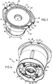
figure 3 est une vue en perspective de dessus de l'accessoire de préparation culinaire illustré sur lafigure 2 , - la
figure 4 est une vue en perspective de dessous de l'accessoire de préparation culinaire illustré sur lesfigures 2 et3 , - la
figure 5 est une vue partielle en perspective du couvercle principal illustré sur lafigure 2 , et de la partie supérieure du réceptacle interne illsutré sur lesfigures 2 à 4 , disposé dans le récipient de travail illustré sur lesfigures 1 et 2 , - la
figure 6 est une vue partielle en perspective de la partie inférieure du réceptacle interne illustré sur lesfigures 2 à 5 , disposé dans le récipient de travail illustré sur lesfigures 1, 2 et5 . - La
figure 1 illustre un appareil électroménager de préparation culinaire 1 comportant une base motorisée 2 et un récipient de travail 3. Un outil de travail rotatif principal 4 est agencé dans le récipient de travail 3. La base motorisée 2 comprend un moteur 6 entraînant en rotation un organe entraîneur 7. - Tel que visible sur la
figure 2 , l'appareil électroménager de préparation culinaire 1 comporte un couvercle principal 9 fermant le récipient de travail 3. Le couvercle principal 9 est par exemple verrouillé par baïonnette sur le récipient de travail 3. Le couvercle principal 9 en position verrouillée est ainsi retenu sur le récipient de travail 3. - Selon une forme de réalisation préférée illustrée sur les figures, le récipient de travail 3 est monté amovible sur la base motorisée 2. Un organe d'entraînement en rotation 8 est agencé dans le récipient de travail 3. L'organe d'entraînement en rotation 8 est entraîné par l'organe entraîneur 7. Ainsi lorsque le récipient de travail 3 est en place sur la base motorisée 2, la base motorisée 2 entraîne en rotation l'organe d'entraînement en rotation 8. L'appareil électroménager de préparation culinaire 1 comporte des moyens de chauffe 5 pour chauffer le récipient de travail 3.
- Plus particulièrement dans l'exemple de réalisation illustré sur les figures, les moyens de chauffe 5 sont portés par le récipient de travail 3. Le récipient de travail 3 est métallique. Le récipient de travail 3 est avantageusement réalisé en acier inoxydable.
- Tel que représenté sur la
figure 2 , un réceptacle interne 11 est disposé dans le récipient de travail 3. Dans cette configuration, l'outil de travail rotatif principal 4 n'est pas présent dans le récipient de travail 3. Un outil de travail rotatif accessoire 12 est agencé dans le réceptacle interne 11. Le réceptacle interne 11 et l'outil de travail rotatif accessoire 12 forment un accessoire de préparation culinaire 10 pour le récipient de travail 3 de l'appareil électroménager de préparation culinaire 1. L'outil de travail rotatif accessoire 12 est entraîné en rotation par l'organe d'entraînement en rotation 8. - Tel que visible sur la
figure 2 , le réceptacle interne 11 comprend une surface d'appui inférieure 14 reposant à l'intérieur du récipient de travail 3. Plus particulièrement dans l'exemple de réalisation illustré sur les figures, la surface d'appui inférieure 14 repose sur un fond du récipient de travail 3. - Dans l'exemple de réalisation illustré sur les figures, le réceptacle interne 11 comprend une embase 15 et une cuve 16 portée par l'embase 15. La cuve 16 présente un fond 17 et une paroi latérale 18. La cuve 16 comporte une cheminée axiale 26 issue du fond 17. La cuve 16 comporte un bord supérieur 19.
- Dans l'exemple de réalisation illustré sur les figures, l'accessoire de préparation culinaire 10 comporte un couvercle d'accessoire 13. Le couvercle d'accessoire 13 est prévu pour obturer au moins partiellement la cuve 16.
- Tel que mieux visible sur les
figures 3 et 4 , le réceptacle interne 11 comporte deux anses rabattables 20. Les deux anses rabattables 20 sont montées pivotantes entre une position rabattue, illustrée sur lesfigures 2 ,3 et 4 , et une position relevée. De préférence, les deux anses rabattables 20 sont agencées de manière symétrique par rapport à la cuve 16. - Dans l'exemple de réalisation illustré sur les figures, les deux anses rabattables 20 sont montées pivotantes sur la cuve 16 entre leur position rabattue et leur position relevée. Plus particulièrement dans l'exemple de réalisation illustré sur les figures, chacune des anses rabattables 20 comporte deux extrémités 21, 22 montées pivotantes sur la cuve 16. Chacune des extrémités 21, 22 est montée pivotante dans un logement 30 ménagé dans une patte 31 issue du bord supérieur 19 de la cuve 16. La patte 31 visible sur la
figure 3 est rabattue à partir de la périphérie du bord supérieur 19, l'autre patte non visible sur lafigure 3 peut être réalisée de manière identique. - Tel que mieux visible sur la
figure 3 , chacune des anses rabattables 20 comporte deux organes d'appui 23. Les organes d'appui 23 sont réalisés en matériau souple. Les organes d'appui 23 sont par exemple surmoulés sur le corps de chacune des anses rabattables 20. - Dans l'exemple de réalisation illustré sur les figures, chaque organe d'appui 23 forme avantageusement un anneau entourant le corps de l'une des anses rabattables 20.
- Tel que visible également sur la
figure 3 , chacune des anses rabattables 20 comporte un organe de préhension 24 réalisé en matériau souple. Les organes de préhension 24 sont par exemple surmoulés sur le corps de chacune des anses rabattables 20. Les organes de préhension 24 sont par exemple réalisés en silicone. - Selon le mode de réalisation préféré illustré sur les figures, chacun des organes de préhension 24 comporte deux organes d'appui 23. De préférence, chaque organe de préhension 24 est disposé entre deux des organes d'appui 23.
- Tel que visible sur la
figure 4 , l'embase 15 du réceptacle interne 11 porte des butées inférieures 28. Les butées inférieures 28 sont réparties autour de la cheminée axiale 26. Les butées inférieures 28 sont réalisées en matériau souple. Les butées inférieures 28 sont avantageusement tubulaires, pour faciliter leur déformation, tout en conservant une certaine rigidité. Les butées inférieures 28 sont par exemple montées autour de pieds cruciformes 29 issus de la face inférieure de l'embase 15. - Le fonctionnement de la présente invention est le suivant.
- L'utilisateur place le récipient de travail 3 sur la base motorisée 2, puis dispose le réceptacle interne 11 dans le récipient de travail 3. L'organe d'entraînement en rotation 8 s'étend alors à l'intérieur de la cheminée axiale 26. Une nervure annulaire 27 issue de l'embase 15 s'étendant autour de l'organe d'entraînement en rotation 8 permet de centrer le réceptacle interne 11 dans le récipient de travail 3. L'utilisateur dispose ensuite l'outil de travail rotatif accessoire 12 dans le réceptacle interne 11. L'outil de travail rotatif accessoire 12 peut alors être entraîné par l'organe d'entraînement en rotation 8. Le réceptacle interne 11 permet de réaliser une préparation mélangée dans la cuve 16 par l'outil de travail rotatif accessoire 12.
- Tel que visible sur les
figures 3 et5 , les anses rabattables 20 du réceptacle interne 11 sont disposées en position rabattue. Les anses rabattables 20 reposent alors sur le bord supérieur 19 de la cuve 16. Plus particulièrement, chaque organe d'appui 23 repose sur le bord supérieur 19 de la cuve 16 lorsque l'anse rabattable 20 correspondante est disposée en position rabattue, tel que visible sur lafigure 5 . - Tel que visible sur les
figures 3 et5 , le couvercle d'accessoire 13 repose sur le bord supérieur 19 de la cuve 16. Toutefois les anses rabattables 20 reposent sur le bord supérieur 19 de la cuve 16 à l'extérieur du couvercle d'accessoire 13, tel que visible sur lafigure 3 . Ainsi les anses rabattables 20 sont librement mobiles entre la position rabattue et la position relevée, et vice-versa, lorsque le couvercle d'accessoire 13 est disposé sur la cuve 16. Lorsque lesdites anses rabattables 20 sont disposées en position rabattue, le couvercle d'accessoire 13 peut être retiré de la cuve 16 ou être mis en place sur la cuve 16 sans déplacer lesdites anses rabattables 20. - Le couvercle d'accessoire 13 comporte deux éléments de préhension 13a, 13b opposés qui peuvent être disposés sur le bord supérieur 19 de la cuve 16 en regard des organes de préhension 24, tel que représenté sur la
figure 3 . Toutefois le couvercle d'accessoire 13 peut être mis en place sur la cuve 16 sans orientation particulière. Le couvercle d'accessoire 13 peut notamment occuper une position dans laquelle les éléments de préhension 13a, 13b sont agencés entre les extrémités 21, 22 des anses rabattables 20. A cet effet les éléments de préhension 13a, 13b peuvent s'étendre entre les pattes 31 recevant pivotantes les extrémités 21, 22 des anses rabattables 20. - Tel que représenté sur la
figure 5 , le couvercle principal 9 ferme le récipient de travail 3. Le couvercle principal 9 fermant le récipient de travail 3 est retenu axialement sur le récipient de travail 3. Le réceptacle interne 11 est disposé dans le récipient de travail 3. L'appareil électroménager de préparation culinaire 1 et l'accesoire de préparation culinaire 10 sont dimensionnés pour que le couvercle principal 9 fermant le récipient de travail 3 déforme élastiquement les organes d'appui 23 pour bloquer le réceptacle interne 11 disposé dans le récipient de travail 3. Lorsque le couvercle principal 9 ferme le récipient de travail 3, le couvercle principal 9 comprime les organes d'appui 23, afin de déformer élastiquement les organes d'appui 23 et de bloquer le réceptacle interne 11 disposé dans le récipient de travail 3. Ainsi les organes d'appui 23 sont comprimés entre le couvercle principal 9 et le réceptacle interne 11. - Tel que visible sur la
figure 6 , les butées inférieures 28 du réceptacle interne 11 s'étendent à distance du fond du récipient de travail 3. - Ainsi le réceptacle interne 11 est maintenu entre le couvercle principal 9 et le fond du récipient de travail 3 lorsque le couvercle principal 9 ferme le récipient de travail 3. La déformation élastique des organes d'appui 23 permet de contribuer au blocage en rotation du réceptacle interne 11 disposé dans le récipient de travail 3. Le réceptacle interne 11 peut être simplement posé dans le récipient de travail 3 par rapport à L'organe d'entraînement en rotation 8, sans indexation particulière. L'organe d'entraînement en rotation 8 engagé dans la cheminée de la cuve 16 permet de centrer le réceptacle interne 11 dans le récipient de travail 3.
- A titre de variante, chacune des anses rabattables 20 peut avantageusement comporter au moins un organe d'appui 23 réalisé en matériau souple.
- A titre de variante, chacun des organes de préhension 24 peut comporter au moins un des organes d'appui 23.
- A titre de variante, les organes d'appui 23 ne sont pas nécessairement annulaires. Les organes d'appui 23 n'entourent pas nécessairement chacune des anses rabattables 20, mais peuvent par exemple s'étendre entre le corps de l'une des anses rabattables 20 et le réceptacle interne 11, et/ou entre le corps de l'une des anses rabattables 20 et le couvercle principal 9.
- A titre de variante, l'embase 15 n'est pas nécessairement assemblée avec la cuve 16. L'embase 15 pourrait notamment être issue de la cuve 16.
- A titre de variante, le couvercle principal 9 n'est pas nécessairement retenu avec le récipient de travail 3, mais peut par exemple être retenu avec la base motorisée 2.
- A titre de variante, les butées inférieures 28 ne sont pas nécessairement formées par des éléments tubulaires élastiquement déformables. Les butées inférieures 28 peuvent être élastiquement déformables sans être nécessairement entièrement réalisées en matériau souple. Les butées inférieures 28 peuvent notamment comporter un élément élastiquement déformable tel qu'un patin inférieur d'appui. Les butées inférieures 28 peuvent être prévues pour prendre appui dans le récipient de travail 3 lorsque le réceptacle interne 11 est disposé dans le récipient de travail 3. Le couvercle principal 9 fermant le récipient de travail 3 déforme alors élastiquement les butées inférieures 28 pour bloquer le réceptacle interne 11 dans le récipient de travail 3. Une telle disposition peut être envisagée en complément ou en substitution de la déformation élastique des organes d'appui 23 par le couvercle principal 9.
- La présente invention n'est nullement limitée à l'exemple de réalisation décrit et à ses variantes, mais englobe de nombreuses modifications dans le cadre des revendications.
Claims (16)
- Réceptacle interne (11) pour récipient de travail (3) d'appareil électroménager de préparation culinaire (1), prévu pour reposer à l'intérieur du récipient de travail (3), comprenant une cuve (16) présentant un fond (17) et une paroi latérale (18), la paroi latérale (18) présentant un bord supérieur (19), caractérisé en ce que le réceptacle interne (11) comporte deux anses rabattables (20) montées pivotantes entre une position rabattue et une position relevée.
- Réceptacle interne (11) selon la revendication 1, caractérisé en ce que chacune des anses rabattables (20) comporte deux extrémités (21, 22) montées pivotantes sur la cuve (16).
- Réceptacle interne (11) selon la revendication 2, caractérisé en ce que chacune des extrémités (21, 22) est montée pivotante dans un logement (30) ménagé dans une patte (31) issue du bord supérieur (19) de la cuve (16).
- Réceptacle interne (11) selon l'une des revendications 1 à 3, caractérisé en ce que chacune des anses rabattables (20) comporte au moins un organe d'appui (23) réalisé en matériau souple.
- Réceptacle interne (11) selon la revendication 4, caractérisé en ce que chacune des anses rabattables (20) comporte au moins un organe de préhension (24) réalisé en matériau souple, et en ce que de préférence chacun des organes de préhension (24) comporte au moins un des organes d'appui (23).
- Réceptacle interne (11) selon l'une des revendications 1 à 5, caractérisé en ce que les anses rabattables (20) reposent sur le bord supérieur (19) de la cuve (16) lorsque lesdites anses rabattables (20) sont disposées en position rabattue.
- Réceptacle interne (11) selon l'une des revendications 4 ou 5 et selon la revendication 6, caractérisé en ce que lesdits organes d'appui (23) reposent sur le bord supérieur (19) de la cuve (16) lorsque les anses rabattables (20) sont disposées en position rabattue.
- Réceptacle interne (11) selon l'une des revendications 1 à 7, caractérisé en ce que la cuve (16) comporte une cheminée axiale (26) issue du fond (17).
- Accessoire de préparation culinaire (10) pour récipient de travail (3) d'appareil électroménager de préparation culinaire (1), comportant un réceptacle interne (11) et un outil de travail rotatif accessoire (12) agencé dans le réceptacle interne (11), caractérisé en ce que le réceptacle interne (11) est conforme à l'une des revendications 1 à 8.
- Accessoire de préparation culinaire (10) selon la revendication 9, caractérisé en ce qu'il comporte un couvercle d'accessoire (13) prévu pour obturer au moins partiellement la cuve (16).
- Accessoire de préparation culinaire (10) selon la revendication 10, caractérisé en ce que le couvercle d'accessoire (13) peut être retiré de la cuve (16) lorsque les anses rabattables (20) sont disposées en position rabattue.
- Accessoire de préparation culinaire (10) selon l'une des revendications 10 ou 11, caractérisé en ce que les anses rabattables (20) sont librement mobiles entre la position rabattue et la position relevée, et vice-versa, lorsque le couvercle d'accessoire (13) est disposé sur la cuve (16).
- Appareil électroménager de préparation culinaire (1), comportant un récipient de travail (3), un couvercle principal (9) fermant le récipient de travail (3), un organe d'entraînement en rotation (8) agencé dans le récipient de travail (3), un réceptacle interne (11) disposé dans le récipient de travail (3), et un outil de travail rotatif accessoire (12) agencé dans le réceptacle interne (11) et entraîné en rotation par l'organe d'entraînement en rotation (8), le réceptacle interne (11) comprenant une surface d'appui inférieure (14) reposant à l'intérieur du récipient de travail (3), caractérisé en ce que le réceptacle interne (11) est conforme à l'une des revendications 1 à 8.
- Appareil électroménager de préparation culinaire (1) selon la revendication 13, caractérisé en ce que le couvercle principal (9) fermant le récipient de travail (3) prend appui sur les anses rabattables (20) disposées en position rabattue lorsque le réceptacle interne (11) est en place dans le récipient de travail (3).
- Appareil électroménager de préparation culinaire (1) selon la revendication 14, caractérisé en ce que le réceptacle interne (11) est conforme à l'une des revendications 4, 5 ou 7, et en ce que le couvercle principal (9) fermant le récipient de travail (3) comprime les organes d'appui (23) lorsque les anses rabattables (20) du réceptacle interne (11) disposé dans le récipient de travail (3) sont disposées en position rabattue et reposent sur le bord supérieur (19) de la cuve (16), pour déformer élastiquement les organes d'appui (23) et bloquer le réceptacle interne (11) disposé dans le récipient de travail (3).
- Appareil électroménager de préparation culinaire (1) selon l'une des revendications 14 ou 15, caractérisé en ce que le réceptacle interne (11) comporte une embase (15) portant des butées inférieures (28) élastiquement déformables, en ce que les butées inférieures (28) sont prévues pour prendre appui dans le récipient de travail (3) lorsque le réceptacle interne (11) est disposé dans le récipient de travail (3), et en ce que le couvercle principal (9) fermant le récipient de travail (3) déforme élastiquement les butées inférieures (28) pour bloquer le réceptacle interne (11) dans le récipient de travail (3).
Priority Applications (1)
| Application Number | Priority Date | Filing Date | Title |
|---|---|---|---|
| EP20161243.9A EP3685719B1 (fr) | 2017-07-03 | 2018-06-25 | Appareil electromenager de preparation culinaire comportant un receptacle interne |
Applications Claiming Priority (1)
| Application Number | Priority Date | Filing Date | Title |
|---|---|---|---|
| FR1756272A FR3068229B1 (fr) | 2017-07-03 | 2017-07-03 | Receptacle interne, accessoire de preparation culinaire et appareil electromenager de preparation culinaire comportant un tel receptacle interne |
Related Child Applications (2)
| Application Number | Title | Priority Date | Filing Date |
|---|---|---|---|
| EP20161243.9A Division EP3685719B1 (fr) | 2017-07-03 | 2018-06-25 | Appareil electromenager de preparation culinaire comportant un receptacle interne |
| EP20161243.9A Division-Into EP3685719B1 (fr) | 2017-07-03 | 2018-06-25 | Appareil electromenager de preparation culinaire comportant un receptacle interne |
Publications (2)
| Publication Number | Publication Date |
|---|---|
| EP3424381A1 true EP3424381A1 (fr) | 2019-01-09 |
| EP3424381B1 EP3424381B1 (fr) | 2020-05-13 |
Family
ID=60202111
Family Applications (2)
| Application Number | Title | Priority Date | Filing Date |
|---|---|---|---|
| EP18179680.6A Active EP3424381B1 (fr) | 2017-07-03 | 2018-06-25 | Réceptacle interne, accessoire de préparation culinaire et appareil électroménager de préparation culinaire comportant un tel réceptacle interne |
| EP20161243.9A Active EP3685719B1 (fr) | 2017-07-03 | 2018-06-25 | Appareil electromenager de preparation culinaire comportant un receptacle interne |
Family Applications After (1)
| Application Number | Title | Priority Date | Filing Date |
|---|---|---|---|
| EP20161243.9A Active EP3685719B1 (fr) | 2017-07-03 | 2018-06-25 | Appareil electromenager de preparation culinaire comportant un receptacle interne |
Country Status (3)
| Country | Link |
|---|---|
| EP (2) | EP3424381B1 (fr) |
| CN (2) | CN209518779U (fr) |
| FR (1) | FR3068229B1 (fr) |
Families Citing this family (1)
| Publication number | Priority date | Publication date | Assignee | Title |
|---|---|---|---|---|
| FR3068229B1 (fr) * | 2017-07-03 | 2020-06-05 | Seb S.A. | Receptacle interne, accessoire de preparation culinaire et appareil electromenager de preparation culinaire comportant un tel receptacle interne |
Citations (5)
| Publication number | Priority date | Publication date | Assignee | Title |
|---|---|---|---|---|
| US1218823A (en) * | 1916-11-25 | 1917-03-13 | Sylvester Woina | Culinary boiler. |
| US1288650A (en) * | 1918-05-24 | 1918-12-24 | Anna Nelson | Cooking utensil. |
| US5974953A (en) * | 1997-01-02 | 1999-11-02 | Sigg Ag Haushaltgerate | Kitchen and table-ware for steam cooking |
| FR2998773A1 (fr) * | 2012-12-03 | 2014-06-06 | Seb Sa | Appareil electromenager de preparation culinaire comportant un recipient de travail comprenant un panier pour la cuisson a la vapeur |
| CN203970183U (zh) * | 2014-04-16 | 2014-12-03 | 中山市美斯特实业有限公司 | 一种用于食品加工机的搅拌桶的提手装置 |
Family Cites Families (5)
| Publication number | Priority date | Publication date | Assignee | Title |
|---|---|---|---|---|
| CN201375408Y (zh) * | 2009-04-17 | 2010-01-06 | 戴宇波 | 一种蒸煮一体化的电压力锅 |
| CN203693362U (zh) * | 2013-12-11 | 2014-07-09 | 美的集团股份有限公司 | 蒸笼组件和电饭煲 |
| CN205649391U (zh) * | 2016-04-01 | 2016-10-19 | 浙江苏泊尔家电制造有限公司 | 用于烹饪器具的蒸笼及烹饪器具 |
| CN206137944U (zh) * | 2016-08-09 | 2017-05-03 | 浙江苏泊尔家电制造有限公司 | 用于烹饪器具的蒸笼及烹饪器具 |
| FR3068229B1 (fr) * | 2017-07-03 | 2020-06-05 | Seb S.A. | Receptacle interne, accessoire de preparation culinaire et appareil electromenager de preparation culinaire comportant un tel receptacle interne |
-
2017
- 2017-07-03 FR FR1756272A patent/FR3068229B1/fr active Active
-
2018
- 2018-06-25 EP EP18179680.6A patent/EP3424381B1/fr active Active
- 2018-06-25 EP EP20161243.9A patent/EP3685719B1/fr active Active
- 2018-07-03 CN CN201821038508.0U patent/CN209518779U/zh active Active
- 2018-07-03 CN CN201810712270.3A patent/CN109199151B/zh active Active
Patent Citations (5)
| Publication number | Priority date | Publication date | Assignee | Title |
|---|---|---|---|---|
| US1218823A (en) * | 1916-11-25 | 1917-03-13 | Sylvester Woina | Culinary boiler. |
| US1288650A (en) * | 1918-05-24 | 1918-12-24 | Anna Nelson | Cooking utensil. |
| US5974953A (en) * | 1997-01-02 | 1999-11-02 | Sigg Ag Haushaltgerate | Kitchen and table-ware for steam cooking |
| FR2998773A1 (fr) * | 2012-12-03 | 2014-06-06 | Seb Sa | Appareil electromenager de preparation culinaire comportant un recipient de travail comprenant un panier pour la cuisson a la vapeur |
| CN203970183U (zh) * | 2014-04-16 | 2014-12-03 | 中山市美斯特实业有限公司 | 一种用于食品加工机的搅拌桶的提手装置 |
Also Published As
| Publication number | Publication date |
|---|---|
| FR3068229B1 (fr) | 2020-06-05 |
| CN209518779U (zh) | 2019-10-22 |
| CN109199151A (zh) | 2019-01-15 |
| FR3068229A1 (fr) | 2019-01-04 |
| EP3685719A1 (fr) | 2020-07-29 |
| CN109199151B (zh) | 2023-03-31 |
| EP3424381B1 (fr) | 2020-05-13 |
| EP3685719B1 (fr) | 2021-12-15 |
Similar Documents
| Publication | Publication Date | Title |
|---|---|---|
| EP1922967B1 (fr) | Appareil électroménager de préparation culinaire chauffant, comportant un récipient de cuisson intermédiaire | |
| EP2731482B1 (fr) | Article culinaire muni d'une poignee cooperant electriquement avec un accessoire amovible | |
| FR2923698A1 (fr) | Appareil electromenager de preparation culinaire comportant un support pour un organe de melange. | |
| EP3311717B1 (fr) | Appareil electromenager de preparation culinaire comportant un couvercle intermediaire | |
| EP2925197A1 (fr) | Appareil electromenager de preparation culinaire comportant un recipient de travail comprenant un panier pour la cuisson a la vapeur | |
| EP2340751A1 (fr) | Ustensile à manipulation simplifiée | |
| EP1900315B1 (fr) | Mixeur ménager de type plongeant comportant un outil de travail présentant la forme d'une vis d'archimède | |
| EP1231855B1 (fr) | Socle de rangement d'accessoires pour un appareil electromenager de preparation culinaire | |
| EP3087885B1 (fr) | Appareil électroménager de préparation culinaire | |
| EP2147624A1 (fr) | Enceinte de travail d'appareil électroménager de préparation culinaire à étanchéité ameliorée | |
| EP2892405A1 (fr) | Appareil de préparation culinaire comportant un crochet de petrissage entraîné selon un mouvement planétaire | |
| EP3685719B1 (fr) | Appareil electromenager de preparation culinaire comportant un receptacle interne | |
| FR2807307A1 (fr) | Systeme d'accessoires pour une rotissoire | |
| CA2854247C (fr) | Appareil de cuisson comportant un accessoire de filtration pouvant occuper deux positions | |
| EP3424378B1 (fr) | Receptacle interne, accessoire de preparation culinaire et appareil electromenager de preparation culinaire comportant un tel receptacle interne | |
| FR2931349A1 (fr) | Appareil electromenager de preparation culinaire comportant un dispositif de securite | |
| FR3057753B1 (fr) | Appareil electromenager de preparation culinaire comportant une base d’alimentation electrique | |
| EP1153563A1 (fr) | Appareil électroménager de préparation culinaire comportant un dispositif de vérrouillage à machoires du couvercle sur le récipient | |
| EP2574259A1 (fr) | Cuiseur vapeur avec dispositif de remplissage du reservoir d'eau en cours de cuisson | |
| FR3057754B1 (fr) | Appareil electromenager de preparation culinaire chauffant comportant un panier vapeur | |
| FR2877557A1 (fr) | Couvercle de fermeture d'un recipient de travail pour un appareil electromenager de preparation culinaire | |
| FR2908617A1 (fr) | Couvercle a degagement de vapeur controle,et dispositif de cuisson,notamment appareil electromenager de preparation culinaire chauffant. | |
| FR2994524A3 (fr) | Dispositif de cuisson multifonctions | |
| EP2407070A1 (fr) | Element de cuisson, notamment pour appareil electrique de cuisson | |
| FR2964547A1 (fr) | Appareil electromenager de preparation culinaire comportant un recipient de travail ferme par un couvercle amovible comprenant une goulotte |
Legal Events
| Date | Code | Title | Description |
|---|---|---|---|
| PUAI | Public reference made under article 153(3) epc to a published international application that has entered the european phase |
Free format text: ORIGINAL CODE: 0009012 |
|
| STAA | Information on the status of an ep patent application or granted ep patent |
Free format text: STATUS: THE APPLICATION HAS BEEN PUBLISHED |
|
| AK | Designated contracting states |
Kind code of ref document: A1 Designated state(s): AL AT BE BG CH CY CZ DE DK EE ES FI FR GB GR HR HU IE IS IT LI LT LU LV MC MK MT NL NO PL PT RO RS SE SI SK SM TR |
|
| AX | Request for extension of the european patent |
Extension state: BA ME |
|
| STAA | Information on the status of an ep patent application or granted ep patent |
Free format text: STATUS: REQUEST FOR EXAMINATION WAS MADE |
|
| 17P | Request for examination filed |
Effective date: 20190704 |
|
| RBV | Designated contracting states (corrected) |
Designated state(s): AL AT BE BG CH CY CZ DE DK EE ES FI FR GB GR HR HU IE IS IT LI LT LU LV MC MK MT NL NO PL PT RO RS SE SI SK SM TR |
|
| GRAP | Despatch of communication of intention to grant a patent |
Free format text: ORIGINAL CODE: EPIDOSNIGR1 |
|
| STAA | Information on the status of an ep patent application or granted ep patent |
Free format text: STATUS: GRANT OF PATENT IS INTENDED |
|
| INTG | Intention to grant announced |
Effective date: 20191209 |
|
| GRAS | Grant fee paid |
Free format text: ORIGINAL CODE: EPIDOSNIGR3 |
|
| GRAA | (expected) grant |
Free format text: ORIGINAL CODE: 0009210 |
|
| STAA | Information on the status of an ep patent application or granted ep patent |
Free format text: STATUS: THE PATENT HAS BEEN GRANTED |
|
| AK | Designated contracting states |
Kind code of ref document: B1 Designated state(s): AL AT BE BG CH CY CZ DE DK EE ES FI FR GB GR HR HU IE IS IT LI LT LU LV MC MK MT NL NO PL PT RO RS SE SI SK SM TR |
|
| REG | Reference to a national code |
Ref country code: GB Ref legal event code: FG4D Free format text: NOT ENGLISH |
|
| REG | Reference to a national code |
Ref country code: CH Ref legal event code: EP |
|
| REG | Reference to a national code |
Ref country code: DE Ref legal event code: R096 Ref document number: 602018004430 Country of ref document: DE |
|
| REG | Reference to a national code |
Ref country code: AT Ref legal event code: REF Ref document number: 1269104 Country of ref document: AT Kind code of ref document: T Effective date: 20200615 |
|
| REG | Reference to a national code |
Ref country code: LT Ref legal event code: MG4D |
|
| REG | Reference to a national code |
Ref country code: NL Ref legal event code: MP Effective date: 20200513 |
|
| PG25 | Lapsed in a contracting state [announced via postgrant information from national office to epo] |
Ref country code: NO Free format text: LAPSE BECAUSE OF FAILURE TO SUBMIT A TRANSLATION OF THE DESCRIPTION OR TO PAY THE FEE WITHIN THE PRESCRIBED TIME-LIMIT Effective date: 20200813 Ref country code: GR Free format text: LAPSE BECAUSE OF FAILURE TO SUBMIT A TRANSLATION OF THE DESCRIPTION OR TO PAY THE FEE WITHIN THE PRESCRIBED TIME-LIMIT Effective date: 20200814 Ref country code: SE Free format text: LAPSE BECAUSE OF FAILURE TO SUBMIT A TRANSLATION OF THE DESCRIPTION OR TO PAY THE FEE WITHIN THE PRESCRIBED TIME-LIMIT Effective date: 20200513 Ref country code: IS Free format text: LAPSE BECAUSE OF FAILURE TO SUBMIT A TRANSLATION OF THE DESCRIPTION OR TO PAY THE FEE WITHIN THE PRESCRIBED TIME-LIMIT Effective date: 20200913 Ref country code: PT Free format text: LAPSE BECAUSE OF FAILURE TO SUBMIT A TRANSLATION OF THE DESCRIPTION OR TO PAY THE FEE WITHIN THE PRESCRIBED TIME-LIMIT Effective date: 20200914 Ref country code: FI Free format text: LAPSE BECAUSE OF FAILURE TO SUBMIT A TRANSLATION OF THE DESCRIPTION OR TO PAY THE FEE WITHIN THE PRESCRIBED TIME-LIMIT Effective date: 20200513 Ref country code: LT Free format text: LAPSE BECAUSE OF FAILURE TO SUBMIT A TRANSLATION OF THE DESCRIPTION OR TO PAY THE FEE WITHIN THE PRESCRIBED TIME-LIMIT Effective date: 20200513 |
|
| PG25 | Lapsed in a contracting state [announced via postgrant information from national office to epo] |
Ref country code: HR Free format text: LAPSE BECAUSE OF FAILURE TO SUBMIT A TRANSLATION OF THE DESCRIPTION OR TO PAY THE FEE WITHIN THE PRESCRIBED TIME-LIMIT Effective date: 20200513 Ref country code: RS Free format text: LAPSE BECAUSE OF FAILURE TO SUBMIT A TRANSLATION OF THE DESCRIPTION OR TO PAY THE FEE WITHIN THE PRESCRIBED TIME-LIMIT Effective date: 20200513 Ref country code: LV Free format text: LAPSE BECAUSE OF FAILURE TO SUBMIT A TRANSLATION OF THE DESCRIPTION OR TO PAY THE FEE WITHIN THE PRESCRIBED TIME-LIMIT Effective date: 20200513 Ref country code: BG Free format text: LAPSE BECAUSE OF FAILURE TO SUBMIT A TRANSLATION OF THE DESCRIPTION OR TO PAY THE FEE WITHIN THE PRESCRIBED TIME-LIMIT Effective date: 20200813 |
|
| REG | Reference to a national code |
Ref country code: AT Ref legal event code: MK05 Ref document number: 1269104 Country of ref document: AT Kind code of ref document: T Effective date: 20200513 |
|
| PG25 | Lapsed in a contracting state [announced via postgrant information from national office to epo] |
Ref country code: AL Free format text: LAPSE BECAUSE OF FAILURE TO SUBMIT A TRANSLATION OF THE DESCRIPTION OR TO PAY THE FEE WITHIN THE PRESCRIBED TIME-LIMIT Effective date: 20200513 Ref country code: NL Free format text: LAPSE BECAUSE OF FAILURE TO SUBMIT A TRANSLATION OF THE DESCRIPTION OR TO PAY THE FEE WITHIN THE PRESCRIBED TIME-LIMIT Effective date: 20200513 |
|
| PG25 | Lapsed in a contracting state [announced via postgrant information from national office to epo] |
Ref country code: CZ Free format text: LAPSE BECAUSE OF FAILURE TO SUBMIT A TRANSLATION OF THE DESCRIPTION OR TO PAY THE FEE WITHIN THE PRESCRIBED TIME-LIMIT Effective date: 20200513 Ref country code: IT Free format text: LAPSE BECAUSE OF FAILURE TO SUBMIT A TRANSLATION OF THE DESCRIPTION OR TO PAY THE FEE WITHIN THE PRESCRIBED TIME-LIMIT Effective date: 20200513 Ref country code: AT Free format text: LAPSE BECAUSE OF FAILURE TO SUBMIT A TRANSLATION OF THE DESCRIPTION OR TO PAY THE FEE WITHIN THE PRESCRIBED TIME-LIMIT Effective date: 20200513 Ref country code: DK Free format text: LAPSE BECAUSE OF FAILURE TO SUBMIT A TRANSLATION OF THE DESCRIPTION OR TO PAY THE FEE WITHIN THE PRESCRIBED TIME-LIMIT Effective date: 20200513 Ref country code: SM Free format text: LAPSE BECAUSE OF FAILURE TO SUBMIT A TRANSLATION OF THE DESCRIPTION OR TO PAY THE FEE WITHIN THE PRESCRIBED TIME-LIMIT Effective date: 20200513 Ref country code: EE Free format text: LAPSE BECAUSE OF FAILURE TO SUBMIT A TRANSLATION OF THE DESCRIPTION OR TO PAY THE FEE WITHIN THE PRESCRIBED TIME-LIMIT Effective date: 20200513 Ref country code: RO Free format text: LAPSE BECAUSE OF FAILURE TO SUBMIT A TRANSLATION OF THE DESCRIPTION OR TO PAY THE FEE WITHIN THE PRESCRIBED TIME-LIMIT Effective date: 20200513 Ref country code: ES Free format text: LAPSE BECAUSE OF FAILURE TO SUBMIT A TRANSLATION OF THE DESCRIPTION OR TO PAY THE FEE WITHIN THE PRESCRIBED TIME-LIMIT Effective date: 20200513 |
|
| REG | Reference to a national code |
Ref country code: DE Ref legal event code: R097 Ref document number: 602018004430 Country of ref document: DE |
|
| PG25 | Lapsed in a contracting state [announced via postgrant information from national office to epo] |
Ref country code: SK Free format text: LAPSE BECAUSE OF FAILURE TO SUBMIT A TRANSLATION OF THE DESCRIPTION OR TO PAY THE FEE WITHIN THE PRESCRIBED TIME-LIMIT Effective date: 20200513 Ref country code: MC Free format text: LAPSE BECAUSE OF FAILURE TO SUBMIT A TRANSLATION OF THE DESCRIPTION OR TO PAY THE FEE WITHIN THE PRESCRIBED TIME-LIMIT Effective date: 20200513 Ref country code: PL Free format text: LAPSE BECAUSE OF FAILURE TO SUBMIT A TRANSLATION OF THE DESCRIPTION OR TO PAY THE FEE WITHIN THE PRESCRIBED TIME-LIMIT Effective date: 20200513 |
|
| PLBE | No opposition filed within time limit |
Free format text: ORIGINAL CODE: 0009261 |
|
| STAA | Information on the status of an ep patent application or granted ep patent |
Free format text: STATUS: NO OPPOSITION FILED WITHIN TIME LIMIT |
|
| PG25 | Lapsed in a contracting state [announced via postgrant information from national office to epo] |
Ref country code: LU Free format text: LAPSE BECAUSE OF NON-PAYMENT OF DUE FEES Effective date: 20200625 |
|
| REG | Reference to a national code |
Ref country code: BE Ref legal event code: MM Effective date: 20200630 |
|
| 26N | No opposition filed |
Effective date: 20210216 |
|
| PG25 | Lapsed in a contracting state [announced via postgrant information from national office to epo] |
Ref country code: IE Free format text: LAPSE BECAUSE OF NON-PAYMENT OF DUE FEES Effective date: 20200625 |
|
| PG25 | Lapsed in a contracting state [announced via postgrant information from national office to epo] |
Ref country code: BE Free format text: LAPSE BECAUSE OF NON-PAYMENT OF DUE FEES Effective date: 20200630 Ref country code: SI Free format text: LAPSE BECAUSE OF FAILURE TO SUBMIT A TRANSLATION OF THE DESCRIPTION OR TO PAY THE FEE WITHIN THE PRESCRIBED TIME-LIMIT Effective date: 20200513 |
|
| REG | Reference to a national code |
Ref country code: CH Ref legal event code: PL |
|
| PG25 | Lapsed in a contracting state [announced via postgrant information from national office to epo] |
Ref country code: LI Free format text: LAPSE BECAUSE OF NON-PAYMENT OF DUE FEES Effective date: 20210630 Ref country code: CH Free format text: LAPSE BECAUSE OF NON-PAYMENT OF DUE FEES Effective date: 20210630 |
|
| PG25 | Lapsed in a contracting state [announced via postgrant information from national office to epo] |
Ref country code: TR Free format text: LAPSE BECAUSE OF FAILURE TO SUBMIT A TRANSLATION OF THE DESCRIPTION OR TO PAY THE FEE WITHIN THE PRESCRIBED TIME-LIMIT Effective date: 20200513 Ref country code: MT Free format text: LAPSE BECAUSE OF FAILURE TO SUBMIT A TRANSLATION OF THE DESCRIPTION OR TO PAY THE FEE WITHIN THE PRESCRIBED TIME-LIMIT Effective date: 20200513 Ref country code: CY Free format text: LAPSE BECAUSE OF FAILURE TO SUBMIT A TRANSLATION OF THE DESCRIPTION OR TO PAY THE FEE WITHIN THE PRESCRIBED TIME-LIMIT Effective date: 20200513 |
|
| PG25 | Lapsed in a contracting state [announced via postgrant information from national office to epo] |
Ref country code: MK Free format text: LAPSE BECAUSE OF FAILURE TO SUBMIT A TRANSLATION OF THE DESCRIPTION OR TO PAY THE FEE WITHIN THE PRESCRIBED TIME-LIMIT Effective date: 20200513 |
|
| GBPC | Gb: european patent ceased through non-payment of renewal fee |
Effective date: 20220625 |
|
| PG25 | Lapsed in a contracting state [announced via postgrant information from national office to epo] |
Ref country code: GB Free format text: LAPSE BECAUSE OF NON-PAYMENT OF DUE FEES Effective date: 20220625 |
|
| PGFP | Annual fee paid to national office [announced via postgrant information from national office to epo] |
Ref country code: DE Payment date: 20250617 Year of fee payment: 8 |
|
| PGFP | Annual fee paid to national office [announced via postgrant information from national office to epo] |
Ref country code: FR Payment date: 20250630 Year of fee payment: 8 |