EP3423793B1 - Bio-sensing device with ambient light cancellation - Google Patents
Bio-sensing device with ambient light cancellation Download PDFInfo
- Publication number
- EP3423793B1 EP3423793B1 EP17760635.7A EP17760635A EP3423793B1 EP 3423793 B1 EP3423793 B1 EP 3423793B1 EP 17760635 A EP17760635 A EP 17760635A EP 3423793 B1 EP3423793 B1 EP 3423793B1
- Authority
- EP
- European Patent Office
- Prior art keywords
- ambient
- light source
- controller
- light
- photodetector
- Prior art date
- Legal status (The legal status is an assumption and is not a legal conclusion. Google has not performed a legal analysis and makes no representation as to the accuracy of the status listed.)
- Active
Links
- 0 C[C@@](CC(*)*)N* Chemical compound C[C@@](CC(*)*)N* 0.000 description 1
Images

Classifications
-
- A—HUMAN NECESSITIES
- A61—MEDICAL OR VETERINARY SCIENCE; HYGIENE
- A61B—DIAGNOSIS; SURGERY; IDENTIFICATION
- A61B5/00—Measuring for diagnostic purposes; Identification of persons
- A61B5/72—Signal processing specially adapted for physiological signals or for diagnostic purposes
- A61B5/7225—Details of analogue processing, e.g. isolation amplifier, gain or sensitivity adjustment, filtering, baseline or drift compensation
-
- A—HUMAN NECESSITIES
- A61—MEDICAL OR VETERINARY SCIENCE; HYGIENE
- A61B—DIAGNOSIS; SURGERY; IDENTIFICATION
- A61B5/00—Measuring for diagnostic purposes; Identification of persons
- A61B5/02—Detecting, measuring or recording for evaluating the cardiovascular system, e.g. pulse, heart rate, blood pressure or blood flow
- A61B5/024—Measuring pulse rate or heart rate
- A61B5/02416—Measuring pulse rate or heart rate using photoplethysmograph signals, e.g. generated by infrared radiation
-
- A—HUMAN NECESSITIES
- A61—MEDICAL OR VETERINARY SCIENCE; HYGIENE
- A61B—DIAGNOSIS; SURGERY; IDENTIFICATION
- A61B5/00—Measuring for diagnostic purposes; Identification of persons
- A61B5/68—Arrangements of detecting, measuring or recording means, e.g. sensors, in relation to patient
- A61B5/6801—Arrangements of detecting, measuring or recording means, e.g. sensors, in relation to patient specially adapted to be attached to or worn on the body surface
- A61B5/6802—Sensor mounted on worn items
- A61B5/681—Wristwatch-type devices
-
- A—HUMAN NECESSITIES
- A61—MEDICAL OR VETERINARY SCIENCE; HYGIENE
- A61B—DIAGNOSIS; SURGERY; IDENTIFICATION
- A61B5/00—Measuring for diagnostic purposes; Identification of persons
- A61B5/72—Signal processing specially adapted for physiological signals or for diagnostic purposes
- A61B5/7203—Signal processing specially adapted for physiological signals or for diagnostic purposes for noise prevention, reduction or removal
-
- H—ELECTRICITY
- H03—ELECTRONIC CIRCUITRY
- H03F—AMPLIFIERS
- H03F3/00—Amplifiers with only discharge tubes or only semiconductor devices as amplifying elements
- H03F3/04—Amplifiers with only discharge tubes or only semiconductor devices as amplifying elements with semiconductor devices only
- H03F3/08—Amplifiers with only discharge tubes or only semiconductor devices as amplifying elements with semiconductor devices only controlled by light
-
- H—ELECTRICITY
- H03—ELECTRONIC CIRCUITRY
- H03F—AMPLIFIERS
- H03F3/00—Amplifiers with only discharge tubes or only semiconductor devices as amplifying elements
- H03F3/45—Differential amplifiers
- H03F3/45071—Differential amplifiers with semiconductor devices only
- H03F3/45076—Differential amplifiers with semiconductor devices only characterised by the way of implementation of the active amplifying circuit in the differential amplifier
- H03F3/45475—Differential amplifiers with semiconductor devices only characterised by the way of implementation of the active amplifying circuit in the differential amplifier using IC blocks as the active amplifying circuit
-
- A—HUMAN NECESSITIES
- A61—MEDICAL OR VETERINARY SCIENCE; HYGIENE
- A61B—DIAGNOSIS; SURGERY; IDENTIFICATION
- A61B2560/00—Constructional details of operational features of apparatus; Accessories for medical measuring apparatus
- A61B2560/02—Operational features
- A61B2560/0242—Operational features adapted to measure environmental factors, e.g. temperature, pollution
- A61B2560/0247—Operational features adapted to measure environmental factors, e.g. temperature, pollution for compensation or correction of the measured physiological value
Definitions
- bio-sensing devices include a photo diode that generates light and a photo detector that senses the light reflected off a person's body, see for example WO2015/164774 . From the reflected light, the device can determine a biophysical property such as heart rate.
- Some bio-sensing devices are provided in the form of wrist watches that measure heart rate.
- a bio-sensing device and method calibrate a time period used to make bio-physical measurements.
- the device initiates a light source sense phase followed by a first ambient sense phase and a second ambient sense phase.
- the device In the light source sense phase, the device is configured to receive a digital value indicative of current through a photodetector while a light source circuit is enabled.
- the device In each of the first and second ambient sense phases, the device is configured to receive digital values while the light source circuit is disabled.
- the device iteratively varies the time period between the phases until the digital value received during the first ambient sense phase is within a threshold of the digital value received during the second ambient sense phase. It then applies the same time separation between the light source sense phase and the ambient phase to equalize the magnitude of the ambient light in the two phases
- An optical-based bio-sensing device includes a light source and a photodetector and takes a reading from the photodetector with the light source enabled during a light source sense phase and then again during an ambient sense phase with the light source disabled.
- the optical-based bio-sensing device is in the form of a wrist-worn watch.
- a controller in the bio-sensing device can assert a signal to turn the light source on and off.
- the controller disables (turns off) the light source during the ambient sense phases, and enables (turns on) the light source during the light source sense phases.
- the only light detected by the photodetector in some examples, may be ambient light, and not light from the light source.
- ambient light e.g., light from a fluorescent light bulb
- the frequency is such that the ambient phase in which ambient light is measured should closely follow the light source phase to ensure that the measurement of ambient light closely approximates the amount of ambient light that was present during the light source phase.
- closely spaced light source and ambient sense phases may require the device to have relatively high signal bandwidth which would result in a higher noise bandwidth and low signal-to-noise (SNR) ratio.
- the controller compares the sensed light signal magnitude during back-to-back ambient sense phases and iteratively varies the timing between such back-to-back ambient sense phases to determine the periodicity (e.g., period or frequency) of the ambient light signal.
- the periodicity e.g., period or frequency
- the bio-sensing device's controller initiates a light source sense phase and then initiates an ambient sense phase at either the periodicity of, or an integer multiple (2, 3, 4,,...) of the periodicity of the ambient light signal.
- the controller may initiate the ambient sense phase such that the interval between the light source sense phase and the ambient sense phase corresponds to either a period or an integer multiple of the period of the ambient light signal.
- the measured ambient signal is subtracted from the measured signal during the light source sense phase, and the heart rate is computed from the resulting difference.
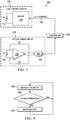
- FIG. 1 shows an example of bio-sensing device 100 in accordance with various embodiments.
- the device includes a light source circuit 110, an optical sense circuit 120, and a controller 130.
- the controller may be any type of processor capable of executing program instructions (e.g., firmware).
- the instructions may be stored in memory internal to the processor or otherwise accessible to the processor.
- the controller is a discrete circuit pre-configured to perform the operations described herein.
- the light source circuit 110 includes a light emitting diode (LED) 112 (or other type of light source) coupled to a driver 114.
- the driver 114 produces a sufficient voltage and/or current to drive current through the LED 112 to produce light.
- the LED is an infrared LED, but generally the LED produces light at wavelength suitable for the intended purpose of the bio-sensing device 100, be it to measure heart rate, peripheral oxygen saturation value, pulse transit time, etc.
- the driver receives a LIGHT_CONTROL signal 131 from the controller 130.
- the LIGHT_CONTROL signal 131 can be asserted to either of two logic states to enable and disable the light source circuit 110, or at least cause the LED 112 to be turned on or turned off.
- the controller 130 For a light source sense phase, the controller 130 asserts the LIGHT_CONTROL signal 131 to a logic state that causes the driver 114 to turn on the LED 112. For an ambient sense phase, the controller 130 asserts the LIGHT_CONTROL signal 131 to the opposite logic state that causes the driver 114 to turn off the LED 112.
- the optical sense circuit 120 in the example of FIG. 1 includes a photo diode 122 (or photo transistor), a transimpedance amplifier 124, and an analog-to-digital converter (ADC) 126.
- One or more feedback resistors R1 may be included as well to set the gain of the transimpedance amplifier 124 to a desired level.
- Incident light on the photo detector 122 (which may be light generated by the LED 112 and reflected off a person's wrist) causes the photo detector 122 to generate a current proportional to the magnitude of the incident light.
- the transimpedance amplifier 124 converts the current to a voltage.
- the ADC 126 then converts the voltage generated by the transimpedance amplifier 124 to a digital value.
- the controller 130 can command the ADC to generate a digital value (i.e., convert the analog voltage from the transimpedance amplifier 124 to a digital value) and provide the digital value to the controller 130.
- a digital value i.e., convert the analog voltage from the transimpedance amplifier 124 to a digital value
- the ADC 126 may continuously digitize the analog voltage from the transimpedance amplifier 124, and the controller 130 reads the current digital value when needed.
- Controller 130 and/or bio-sensing device 100 may implement one or more of the ambient light cancellation techniques described herein.
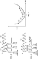
- FIG. 2 shows an example of a periodic ambient light signal 150. Also shown are a light source sense phase 152, a first ambient sense phase 162 (AMB), and a second ambient sense phase 172 (AMB'). In each of these phases, the controller receives a digital value from the ADC 124.
- the digital value read from the ADC is a signal from the photo diode that was sampled (e.g., converted to a voltage and digitized) while the LED 112 was enabled (on).
- the digital value is generated and read at the end of the light source sense phase, but alternatively could be obtained any time during the light source sense phase.
- the digital value represents the measured light value and is denoted as VL.
- the controller 130 performs the first ambient sense phase 162 and reads another digital value from the optical sense circuit 120 this time with the LED 112 disabled (off).
- the measured value is denoted as VA to signify the measured light signal during an ambient sense phase.
- the controller implements the second ambient sense phase 172 after a tsep time period following the first ambient sense phase 162.
- the measured value during the second ambient sense phase is denoted as VA'. Accordingly, the three measured light signal values-VL, VA and VA'-are measured with a timing of tsep between each measurement.
- the value of tsep is not aligned to the periodicity (or period) of the ambient light signal 150 and, as a result the magnitude of VA is significantly different the magnitude of VA'.
- the ambient sense phase is not executed an integer multiple of ambient signal cycles after the light source sense phase, the magnitude of the measured ambient signal (VA) is not likely to sufficiently approximate the magnitude of the ambient light signal incident on the photodetector 122 during the light source sense phase 152. Any resulting computation of heart rate or other biophysical parameter may not be sufficiently accurate.
- tones in the ambient light can also exist in the subtracted value (between the light source sense phase and the ambient phase) and can be mistakenly determined as the heart rate.
- the controller 130 is configured to iteratively vary the size of tsep until the digital value received from the ADC 126 during the first ambient sense phase is within a threshold of the digital value received during the second ambient sense phase.
- the digital values used for the comparison could be the average values taken over multiple cycles.
- the controller iteratively increases the size of tsep until VA approximately equals VA'.
- FIG. 3 An example of this result is illustrated in FIG. 3 .
- the plot of FIG. 3 is similar to that of FIG. 2 but tsep has been increased to the point at which VA approximately equals VA'.
- the magnitude of the measured ambient signal (VA) measured during the ambient sense phase 162 approximately equals the magnitude of the ambient light signal incident on the photodetector 122 during the light source sense phase 152.
- the measured ambient light value VA can be subtracted from the measured light signal during the light source sense phase (VL) to generate a sufficiently accurate value for the magnitude of the light reflected off the person from just the LED 112. Any bio-physical calculation made using this latter value will not be based on much or any ambient light and thus be more accurate than if the ambient light were not factored out of the measurements and calculations.
- FIG. 4 illustrates a method in accordance with various embodiments.
- the method includes measuring VA and VA' for a particular setting for tsep.
- the value of tsep may be set to a default value implemented by the controller 130.
- the controller 130 reads a first digital value from the ADC (VA) and, after the time tsep, a second digital value (VA').
- VA ADC
- VA' a second digital value
- the controller 130 then computes the difference between the VA and VA' values (or the averaged values) and determines whether the difference is less than a threshold.
- the threshold is configured in the controller 130.
- the threshold is relatively small and represents a value below the difference between VA and VA' is considered small enough such that VA and VA' are determined to be substantially equal.
- the value of tsep represents the period of the underlying ambient light signal.
- the absolute value of the difference between VA and VA' is compared to the threshold.
- the controller 130 computes the square of the difference between VA and VA' and compares the square of the difference to a threshold.
- the controller 204 increases the size of tsep and control loops back to 200 and the process repeats. The process iterates until the difference between VA and VA' is less than threshold at which time the value of tsep approximates the period of the ambient light signal. That value of tsep is used to compute the biophysical parameter through acquisition of a digital value during a light source sense phase and a digital value from an ambient sense phase a tsep period of time following the light source sense phase.
- the ambient sense phase is an integer multiple of tsep values following the light source sense phase.
- FIG. 5 illustrates the relationship between the difference between successive ambient light samples (VA and VA') separated by varying values of tsep.
- the difference between VA and VA' is illustrated in FIG. 5 as the absolute value of the difference, but an alternative representation could include the square of the difference.
- tsep t0
- the method of FIG. 4 includes determining at 202 whether the difference value is less than the threshold.
- the method may include sweeping the value of tsep from a higher value to a lower value, or vice versa and determining the value of tsep for which the difference value (VA-VA') is the lowest.
- each measurement of VA and VA' for a given value of tsep includes multiple measurements that are averaged together by the controller 130 as described hereinabove.
- the controller may determine the value of tsep as to by determining the value of tsep for which the neighboring difference values on either side are greater than the difference value at a given tsep. In some embodiments, the controller determines the value of tsep for which n neighboring difference values are greater than the difference value at a given tsep. For example, the value of n may be 6, meaning that 6 neighboring difference values (e.g., the three values 240 and the three values 260) must be greater than the value 250 for the tsep value corresponding to 250 to be determined to be the value of tsep to be used for the subsequent biophysical measurements.
- an optical bio-sensing device has multiple photodiodes, with one photodiode being used for calibration purposes to calibrate the value of tsep and the other photodiode used to measure the biophysical parameter.
- FIG. 6 shows an embodiment of a bio-sensing device including a light source circuit 110 (including an LED 112 and driver 114 as described hereinabove), a controller 130 and an alternative optical sense circuit 320 from that shown in FIG. 1 .
- the optical sense circuit 320 in FIG. 6 includes a pair of photodiodes 322 and 332. Each photodiode is coupled to a corresponding transimpedance amplifier 324, 334.
- the current generated from photodiode 322 is converted to an analog voltage by transimpedance amplifier 324 and the current generated from photodiode 332 is converted to an analog voltage by transimpedance amplifier 334.
- the analog voltage representations of photodiode current are provided to an ADC 340.
- the ADC 340 may be a multi-channel ADC and thus be capable of digitizing individual analog inputs such as inputs from the transimpedance amplifiers 324 and 334. Other implementations may include separate ADCs rather than one multi-channel ADC. Further still, a single transimpedance amplifier could be used for the two photodiodes 322, 332.
- the controller 130 can read digital values from the ADC 340 for either of the photodiodes.
- the bio-sensing device is implemented in the form of a wrist-worn device similar to a watch, and may include a time function like a watch.
- FIG. 7 shows an example of such an embodiment, the device includes a wrist-worn band 400 and a housing 410 containing the light source (e.g., photodiode 122, 322, 332), the transimpedance amplifier (124, 324, 334), the ADC (126, 340), and other components of the device not shown (e.g., display, battery).
- the housing 410 may comprise metal, plastic or other suitable material and have opposing surfaces 410a and 410b. Surface 410b rests adjacent the person's skin when the watch is strapped to the person's wrist. Surface 410a is opposite surface 410a and thus on the side of the device opposite the wrist.
- the photodiode 324 of FIG. 6 is provided on surface 410b and the photodiode 322 is provided on surface 410a. Each photodiode may be mounted within the housing 410 may be exposed to the outside of the housing through a suitably sized aperture.
- the photodiode adjacent the person's wrist is the photodiode used by the controller to measure the biophysical parameter. In the example of FIG. 7 , that measurement photodiode is photodiode 324. Because photodiode 324 is in direct or near direct contact with the person's wrist, not much ambient light is received into that photodiode.
- the controller in the device needs to perform ambient sense phases to subtract out the ambient light signal from the light source sensing phases as described hereinabove.
- the amount of ambient light received by photodiode 324 may be variable and may affect the quality of the ambient signal for purposes of computing tsep to approximate the period of the periodic ambient light signal.
- photodiode 322 is used to acquire and compare the values of VA and VA' as described hereinabove. After the value of tsep is determined so as to approximate the period of the ambient light signal, that value of tsep is used to make biophysical parameter measurements.
- the controller 130 reads a digital value from the ADC 340 during a light source sense phase for photodiode 324 and then reads another digital value from the ADC also for photodiode 324 during an ambient sense phase spaced apart from the light source sense phase by an integer multiple of tsep, where tsep was determined using the photodiode 322.
- the device performs the calibration technique described herein upon power-on and/or at discrete intervals during operation (e.g., once every minute, every 5 minutes, and so on).
- the described calibration techniques render the resulting computed bio-physical parameter more accurate.
- controller 130 may determine (or estimate) a value indicative of an integer multiple of a period of ambient light based on one or more ambient light measurements, and control a time interval (or time period) between a light source-enabled measurement and a first ambient measurement (i.e., a light source-disabled measurement) based on the determined value.
- the first ambient measurement may be used to cancel ambient light from the light-source enabled measurement.
- controller 130 may determine the value indicative of the integer multiple of the period of the ambient light phase by adjusting the time interval between two or more successive ambient light measurements such that the successive ambient light measurements are approximately equal.
- controller 130 may use a single light detector (e.g., a photodiode) to perform the successive ambient light measurements, the first ambient light measurement, and the light source-enabled measurements.
- controller 130 may use separate light detectors (e.g., photodiodes) to perform the successive ambient light measurements and the light source-enabled measurements.
- controller 130 may use a first light detector on a first face of a device that is proximate to the skin of a user of the device to perform the light source-enabled measurement and the first ambient light measurement, and use a second light detector on a second face of the device to perform the successive ambient light measurements (for determining the time interval between the light source-enabled measurement and the first ambient light measurement).
- the second face of the device may be opposite the first face of the device.
- the exposure of the second face of the device to ambient light may be greater than the exposure of the first face of the device to ambient light.
- the second face of the device may be facing a direction that is opposite the skin of a user of the device.
Landscapes
- Health & Medical Sciences (AREA)
- Life Sciences & Earth Sciences (AREA)
- Engineering & Computer Science (AREA)
- Physics & Mathematics (AREA)
- Public Health (AREA)
- Veterinary Medicine (AREA)
- Pathology (AREA)
- Biomedical Technology (AREA)
- Heart & Thoracic Surgery (AREA)
- Medical Informatics (AREA)
- Molecular Biology (AREA)
- Surgery (AREA)
- Animal Behavior & Ethology (AREA)
- General Health & Medical Sciences (AREA)
- Biophysics (AREA)
- Signal Processing (AREA)
- Physiology (AREA)
- Cardiology (AREA)
- Computer Vision & Pattern Recognition (AREA)
- Artificial Intelligence (AREA)
- Psychiatry (AREA)
- Power Engineering (AREA)
- Measuring Pulse, Heart Rate, Blood Pressure Or Blood Flow (AREA)
- Measurement Of The Respiration, Hearing Ability, Form, And Blood Characteristics Of Living Organisms (AREA)
- Investigating Or Analysing Materials By Optical Means (AREA)
- Pulmonology (AREA)
- Spectroscopy & Molecular Physics (AREA)
- Optics & Photonics (AREA)
Applications Claiming Priority (3)
| Application Number | Priority Date | Filing Date | Title |
|---|---|---|---|
| US201662301326P | 2016-02-29 | 2016-02-29 | |
| US15/298,764 US10362994B2 (en) | 2016-02-29 | 2016-10-20 | Bio-sensing device with ambient light cancellation |
| PCT/US2017/019994 WO2017151648A1 (en) | 2016-02-29 | 2017-02-28 | Bio-sensing device with ambient light cancellation |
Publications (3)
| Publication Number | Publication Date |
|---|---|
| EP3423793A1 EP3423793A1 (en) | 2019-01-09 |
| EP3423793A4 EP3423793A4 (en) | 2019-02-27 |
| EP3423793B1 true EP3423793B1 (en) | 2019-09-04 |
Family
ID=59678658
Family Applications (1)
| Application Number | Title | Priority Date | Filing Date |
|---|---|---|---|
| EP17760635.7A Active EP3423793B1 (en) | 2016-02-29 | 2017-02-28 | Bio-sensing device with ambient light cancellation |
Country Status (5)
| Country | Link |
|---|---|
| US (1) | US10362994B2 (cg-RX-API-DMAC7.html) |
| EP (1) | EP3423793B1 (cg-RX-API-DMAC7.html) |
| JP (1) | JP6839717B2 (cg-RX-API-DMAC7.html) |
| CN (1) | CN109073428B (cg-RX-API-DMAC7.html) |
| WO (1) | WO2017151648A1 (cg-RX-API-DMAC7.html) |
Families Citing this family (21)
| Publication number | Priority date | Publication date | Assignee | Title |
|---|---|---|---|---|
| US8498695B2 (en) | 2006-12-22 | 2013-07-30 | Novadaq Technologies Inc. | Imaging system with a single color image sensor for simultaneous fluorescence and color video endoscopy |
| AU2016351730B2 (en) | 2015-11-13 | 2019-07-11 | Novadaq Technologies Inc. | Systems and methods for illumination and imaging of a target |
| WO2017127929A1 (en) | 2016-01-26 | 2017-08-03 | Novadaq Technologies Inc. | Configurable platform |
| CA3027592A1 (en) | 2016-06-14 | 2017-12-21 | John Josef Paul FENGLER | Methods and systems for adaptive imaging for low light signal enhancement in medical visualization |
| WO2018145193A1 (en) * | 2017-02-10 | 2018-08-16 | Novadaq Technologies ULC | Open-field handheld fluorescence imaging systems and methods |
| CN107621641B (zh) * | 2017-09-20 | 2019-06-21 | 歌尔股份有限公司 | 红外测障方法、装置及机器人 |
| JP7183682B2 (ja) * | 2018-10-12 | 2022-12-06 | 株式会社リコー | 読取装置、画像読取装置、画像形成装置、及び読取方法 |
| TWI699096B (zh) * | 2018-12-10 | 2020-07-11 | 新加坡商光寶科技新加坡私人有限公司 | 環境光濾除方法 |
| DE102019112769B4 (de) * | 2019-05-15 | 2022-06-15 | Bundesrepublik Deutschland, Vertreten Durch Das Bundesministerium Für Wirtschaft Und Energie, Dieses Vertreten Durch Den Präsidenten Der Physikalisch-Technischen Bundesanstalt | Schaltung zum Messen impulsförmiger elektrischer Signale sowie Lichtmessgerät mit einer derartigen Schaltung |
| CN112806972B (zh) * | 2019-11-18 | 2023-04-07 | Oppo广东移动通信有限公司 | Ppg测量电路和方法、可穿戴电子设备 |
| WO2021097755A1 (zh) * | 2019-11-21 | 2021-05-27 | 深圳市汇顶科技股份有限公司 | 生物特征检测方法、生物特征检测装置和电子装置 |
| CN111093486B (zh) * | 2019-11-25 | 2022-09-16 | 深圳市汇顶科技股份有限公司 | 生物特征检测方法、生物特征检测装置和电子装置 |
| CN114271783B (zh) * | 2020-09-27 | 2024-01-30 | 北京小米移动软件有限公司 | 皮肤检测装置、方法和终端 |
| KR20220086783A (ko) * | 2020-12-16 | 2022-06-24 | 삼성전자주식회사 | 전자 장치 및 전자 장치의 동작 방법 |
| CN115131451A (zh) * | 2021-03-24 | 2022-09-30 | 鸿富锦精密电子(郑州)有限公司 | 红外激光辐射强度可视化方法、电子设备及存储介质 |
| TWI766774B (zh) * | 2021-07-26 | 2022-06-01 | 神煜電子股份有限公司 | 心率血氧監測裝置 |
| US11808945B2 (en) * | 2021-09-07 | 2023-11-07 | Meta Platforms Technologies, Llc | Eye data and operation of head mounted device |
| CN114052696B (zh) * | 2021-11-19 | 2024-03-26 | 恒玄科技(上海)股份有限公司 | 一种ppg信号检测方法、组件及可穿戴设备 |
| CN114877993A (zh) * | 2022-05-26 | 2022-08-09 | 芯海科技(深圳)股份有限公司 | 环境光检测电路、方法及光电容积脉搏波测量设备 |
| EP4443410A1 (en) * | 2023-04-06 | 2024-10-09 | MotionMiners GmbH | System and method for ergonomic training |
| CN117347750A (zh) * | 2023-09-15 | 2024-01-05 | 深圳市志奋领科技有限公司 | 一种抵抗周期性光干扰的方法及装置 |
Family Cites Families (16)
| Publication number | Priority date | Publication date | Assignee | Title |
|---|---|---|---|---|
| US5460182A (en) * | 1992-09-14 | 1995-10-24 | Sextant Medical Corporation | Tissue penetrating apparatus and methods |
| US6748259B1 (en) | 2000-06-15 | 2004-06-08 | Spectros Corporation | Optical imaging of induced signals in vivo under ambient light conditions |
| DE112004002988B4 (de) | 2004-10-15 | 2013-06-06 | Nagasaki Prefectural Government | Instrument zum nichtinvasiven Messen des Blutzuckerpegels |
| EP2131731B1 (en) | 2007-02-16 | 2014-04-09 | Galvanic Limited | Biosensor system |
| GB0816592D0 (en) | 2008-09-11 | 2008-10-15 | Sgs Thomson Microelectronics | Optical Sensor and Sensing Method |
| US8504130B2 (en) * | 2008-10-07 | 2013-08-06 | Covidien Lp | Non-interfering physiological sensor system |
| US8140143B2 (en) | 2009-04-16 | 2012-03-20 | Massachusetts Institute Of Technology | Washable wearable biosensor |
| US8922788B2 (en) * | 2012-12-22 | 2014-12-30 | Covidien Lp | Methods and systems for determining a probe-off condition in a medical device |
| FI126338B (en) * | 2013-05-15 | 2016-10-14 | Pulseon Oy | Portable heart rate monitor |
| US10512407B2 (en) | 2013-06-24 | 2019-12-24 | Fitbit, Inc. | Heart rate data collection |
| KR20150098940A (ko) * | 2014-02-21 | 2015-08-31 | 이동화 | 생체신호 감지장치 |
| WO2015164774A1 (en) | 2014-04-25 | 2015-10-29 | The Trustees Of Dartmouth College | Fluorescence guided surgical systems and methods gated on ambient light |
| ES2621429T3 (es) * | 2014-06-30 | 2017-07-04 | Koninklijke Philips N.V. | Aparato y método de sensor de fotopletismografía |
| KR20160019294A (ko) * | 2014-08-11 | 2016-02-19 | 삼성전자주식회사 | 신호 처리 방법 및 장치 |
| CN104706336B (zh) * | 2014-12-31 | 2017-06-27 | 歌尔股份有限公司 | 一种光电式脉搏信号测量方法、装置及测量设备 |
| CN105758452B (zh) * | 2016-02-04 | 2018-05-15 | 歌尔股份有限公司 | 一种可穿戴设备的佩戴状态检测方法和装置 |
-
2016
- 2016-10-20 US US15/298,764 patent/US10362994B2/en active Active
-
2017
- 2017-02-28 JP JP2018545431A patent/JP6839717B2/ja active Active
- 2017-02-28 CN CN201780013777.3A patent/CN109073428B/zh active Active
- 2017-02-28 EP EP17760635.7A patent/EP3423793B1/en active Active
- 2017-02-28 WO PCT/US2017/019994 patent/WO2017151648A1/en not_active Ceased
Non-Patent Citations (1)
| Title |
|---|
| None * |
Also Published As
| Publication number | Publication date |
|---|---|
| CN109073428A (zh) | 2018-12-21 |
| EP3423793A1 (en) | 2019-01-09 |
| US20170245803A1 (en) | 2017-08-31 |
| EP3423793A4 (en) | 2019-02-27 |
| WO2017151648A8 (en) | 2018-11-15 |
| CN109073428B (zh) | 2021-09-28 |
| JP6839717B2 (ja) | 2021-03-10 |
| US10362994B2 (en) | 2019-07-30 |
| JP2019510558A (ja) | 2019-04-18 |
| WO2017151648A1 (en) | 2017-09-08 |
Similar Documents
| Publication | Publication Date | Title |
|---|---|---|
| EP3423793B1 (en) | Bio-sensing device with ambient light cancellation | |
| EP3016582B1 (en) | Photoplethysmography sensor apparatus and method | |
| US9743838B2 (en) | Circuits and methods for photoplethysmographic sensors | |
| US10433738B2 (en) | Method and apparatus for optical sensing of tissue variation at increased accuracy | |
| TWI734677B (zh) | 用於光學式鄰近偵測器的精確度估計 | |
| TWI640293B (zh) | Photoelectric detection equipment and integrated circuit | |
| US20160278712A1 (en) | Living Body Information Sensor | |
| JP2019510558A5 (cg-RX-API-DMAC7.html) | ||
| US11344234B2 (en) | Circuit arrangement for an optical monitoring system and method for optical monitoring | |
| CN108366744A (zh) | 用于检测生理参数的系统及方法 | |
| CN116430213A (zh) | 信号检测电路、方法、集成电路、检测装置及电子设备 | |
| US20180028077A1 (en) | Circuits and methods for photoplethysmographic sensors | |
| CN113965953B (zh) | 一种可穿戴设备的控制方法及可穿戴设备 | |
| US11689209B2 (en) | Analog-to-digital converter circuitry, an integrated circuit device, a photoplethysmogram detector, a wearable device and a method for analog-to-digital conversion | |
| JP7245035B2 (ja) | 生体情報測定装置、生体情報測定システム、生体情報測定方法およびプログラム |
Legal Events
| Date | Code | Title | Description |
|---|---|---|---|
| STAA | Information on the status of an ep patent application or granted ep patent |
Free format text: STATUS: THE INTERNATIONAL PUBLICATION HAS BEEN MADE |
|
| PUAI | Public reference made under article 153(3) epc to a published international application that has entered the european phase |
Free format text: ORIGINAL CODE: 0009012 |
|
| STAA | Information on the status of an ep patent application or granted ep patent |
Free format text: STATUS: REQUEST FOR EXAMINATION WAS MADE |
|
| 17P | Request for examination filed |
Effective date: 20181001 |
|
| AK | Designated contracting states |
Kind code of ref document: A1 Designated state(s): AL AT BE BG CH CY CZ DE DK EE ES FI FR GB GR HR HU IE IS IT LI LT LU LV MC MK MT NL NO PL PT RO RS SE SI SK SM TR |
|
| AX | Request for extension of the european patent |
Extension state: BA ME |
|
| A4 | Supplementary search report drawn up and despatched |
Effective date: 20190128 |
|
| RIC1 | Information provided on ipc code assigned before grant |
Ipc: A61B 5/024 20060101ALI20190122BHEP Ipc: A61B 5/00 20060101ALI20190122BHEP Ipc: G01D 18/00 20060101AFI20190122BHEP |
|
| GRAP | Despatch of communication of intention to grant a patent |
Free format text: ORIGINAL CODE: EPIDOSNIGR1 |
|
| STAA | Information on the status of an ep patent application or granted ep patent |
Free format text: STATUS: GRANT OF PATENT IS INTENDED |
|
| DAV | Request for validation of the european patent (deleted) | ||
| DAX | Request for extension of the european patent (deleted) | ||
| INTG | Intention to grant announced |
Effective date: 20190516 |
|
| GRAS | Grant fee paid |
Free format text: ORIGINAL CODE: EPIDOSNIGR3 |
|
| GRAA | (expected) grant |
Free format text: ORIGINAL CODE: 0009210 |
|
| STAA | Information on the status of an ep patent application or granted ep patent |
Free format text: STATUS: THE PATENT HAS BEEN GRANTED |
|
| AK | Designated contracting states |
Kind code of ref document: B1 Designated state(s): AL AT BE BG CH CY CZ DE DK EE ES FI FR GB GR HR HU IE IS IT LI LT LU LV MC MK MT NL NO PL PT RO RS SE SI SK SM TR |
|
| REG | Reference to a national code |
Ref country code: GB Ref legal event code: FG4D |
|
| REG | Reference to a national code |
Ref country code: CH Ref legal event code: EP |
|
| REG | Reference to a national code |
Ref country code: AT Ref legal event code: REF Ref document number: 1176015 Country of ref document: AT Kind code of ref document: T Effective date: 20190915 |
|
| REG | Reference to a national code |
Ref country code: DE Ref legal event code: R096 Ref document number: 602017006800 Country of ref document: DE |
|
| REG | Reference to a national code |
Ref country code: IE Ref legal event code: FG4D |
|
| REG | Reference to a national code |
Ref country code: NL Ref legal event code: MP Effective date: 20190904 |
|
| REG | Reference to a national code |
Ref country code: LT Ref legal event code: MG4D |
|
| PG25 | Lapsed in a contracting state [announced via postgrant information from national office to epo] |
Ref country code: FI Free format text: LAPSE BECAUSE OF FAILURE TO SUBMIT A TRANSLATION OF THE DESCRIPTION OR TO PAY THE FEE WITHIN THE PRESCRIBED TIME-LIMIT Effective date: 20190904 Ref country code: HR Free format text: LAPSE BECAUSE OF FAILURE TO SUBMIT A TRANSLATION OF THE DESCRIPTION OR TO PAY THE FEE WITHIN THE PRESCRIBED TIME-LIMIT Effective date: 20190904 Ref country code: SE Free format text: LAPSE BECAUSE OF FAILURE TO SUBMIT A TRANSLATION OF THE DESCRIPTION OR TO PAY THE FEE WITHIN THE PRESCRIBED TIME-LIMIT Effective date: 20190904 Ref country code: NO Free format text: LAPSE BECAUSE OF FAILURE TO SUBMIT A TRANSLATION OF THE DESCRIPTION OR TO PAY THE FEE WITHIN THE PRESCRIBED TIME-LIMIT Effective date: 20191204 Ref country code: LT Free format text: LAPSE BECAUSE OF FAILURE TO SUBMIT A TRANSLATION OF THE DESCRIPTION OR TO PAY THE FEE WITHIN THE PRESCRIBED TIME-LIMIT Effective date: 20190904 Ref country code: BG Free format text: LAPSE BECAUSE OF FAILURE TO SUBMIT A TRANSLATION OF THE DESCRIPTION OR TO PAY THE FEE WITHIN THE PRESCRIBED TIME-LIMIT Effective date: 20191204 |
|
| PG25 | Lapsed in a contracting state [announced via postgrant information from national office to epo] |
Ref country code: RS Free format text: LAPSE BECAUSE OF FAILURE TO SUBMIT A TRANSLATION OF THE DESCRIPTION OR TO PAY THE FEE WITHIN THE PRESCRIBED TIME-LIMIT Effective date: 20190904 Ref country code: LV Free format text: LAPSE BECAUSE OF FAILURE TO SUBMIT A TRANSLATION OF THE DESCRIPTION OR TO PAY THE FEE WITHIN THE PRESCRIBED TIME-LIMIT Effective date: 20190904 Ref country code: AL Free format text: LAPSE BECAUSE OF FAILURE TO SUBMIT A TRANSLATION OF THE DESCRIPTION OR TO PAY THE FEE WITHIN THE PRESCRIBED TIME-LIMIT Effective date: 20190904 Ref country code: GR Free format text: LAPSE BECAUSE OF FAILURE TO SUBMIT A TRANSLATION OF THE DESCRIPTION OR TO PAY THE FEE WITHIN THE PRESCRIBED TIME-LIMIT Effective date: 20191205 Ref country code: ES Free format text: LAPSE BECAUSE OF FAILURE TO SUBMIT A TRANSLATION OF THE DESCRIPTION OR TO PAY THE FEE WITHIN THE PRESCRIBED TIME-LIMIT Effective date: 20190904 |
|
| REG | Reference to a national code |
Ref country code: AT Ref legal event code: MK05 Ref document number: 1176015 Country of ref document: AT Kind code of ref document: T Effective date: 20190904 |
|
| PG25 | Lapsed in a contracting state [announced via postgrant information from national office to epo] |
Ref country code: PL Free format text: LAPSE BECAUSE OF FAILURE TO SUBMIT A TRANSLATION OF THE DESCRIPTION OR TO PAY THE FEE WITHIN THE PRESCRIBED TIME-LIMIT Effective date: 20190904 Ref country code: EE Free format text: LAPSE BECAUSE OF FAILURE TO SUBMIT A TRANSLATION OF THE DESCRIPTION OR TO PAY THE FEE WITHIN THE PRESCRIBED TIME-LIMIT Effective date: 20190904 Ref country code: AT Free format text: LAPSE BECAUSE OF FAILURE TO SUBMIT A TRANSLATION OF THE DESCRIPTION OR TO PAY THE FEE WITHIN THE PRESCRIBED TIME-LIMIT Effective date: 20190904 Ref country code: NL Free format text: LAPSE BECAUSE OF FAILURE TO SUBMIT A TRANSLATION OF THE DESCRIPTION OR TO PAY THE FEE WITHIN THE PRESCRIBED TIME-LIMIT Effective date: 20190904 Ref country code: PT Free format text: LAPSE BECAUSE OF FAILURE TO SUBMIT A TRANSLATION OF THE DESCRIPTION OR TO PAY THE FEE WITHIN THE PRESCRIBED TIME-LIMIT Effective date: 20200106 Ref country code: RO Free format text: LAPSE BECAUSE OF FAILURE TO SUBMIT A TRANSLATION OF THE DESCRIPTION OR TO PAY THE FEE WITHIN THE PRESCRIBED TIME-LIMIT Effective date: 20190904 Ref country code: IT Free format text: LAPSE BECAUSE OF FAILURE TO SUBMIT A TRANSLATION OF THE DESCRIPTION OR TO PAY THE FEE WITHIN THE PRESCRIBED TIME-LIMIT Effective date: 20190904 |
|
| PG25 | Lapsed in a contracting state [announced via postgrant information from national office to epo] |
Ref country code: SK Free format text: LAPSE BECAUSE OF FAILURE TO SUBMIT A TRANSLATION OF THE DESCRIPTION OR TO PAY THE FEE WITHIN THE PRESCRIBED TIME-LIMIT Effective date: 20190904 Ref country code: CZ Free format text: LAPSE BECAUSE OF FAILURE TO SUBMIT A TRANSLATION OF THE DESCRIPTION OR TO PAY THE FEE WITHIN THE PRESCRIBED TIME-LIMIT Effective date: 20190904 Ref country code: IS Free format text: LAPSE BECAUSE OF FAILURE TO SUBMIT A TRANSLATION OF THE DESCRIPTION OR TO PAY THE FEE WITHIN THE PRESCRIBED TIME-LIMIT Effective date: 20200224 Ref country code: SM Free format text: LAPSE BECAUSE OF FAILURE TO SUBMIT A TRANSLATION OF THE DESCRIPTION OR TO PAY THE FEE WITHIN THE PRESCRIBED TIME-LIMIT Effective date: 20190904 |
|
| REG | Reference to a national code |
Ref country code: DE Ref legal event code: R097 Ref document number: 602017006800 Country of ref document: DE |
|
| PLBE | No opposition filed within time limit |
Free format text: ORIGINAL CODE: 0009261 |
|
| STAA | Information on the status of an ep patent application or granted ep patent |
Free format text: STATUS: NO OPPOSITION FILED WITHIN TIME LIMIT |
|
| PG2D | Information on lapse in contracting state deleted |
Ref country code: IS |
|
| PG25 | Lapsed in a contracting state [announced via postgrant information from national office to epo] |
Ref country code: DK Free format text: LAPSE BECAUSE OF FAILURE TO SUBMIT A TRANSLATION OF THE DESCRIPTION OR TO PAY THE FEE WITHIN THE PRESCRIBED TIME-LIMIT Effective date: 20190904 Ref country code: IS Free format text: LAPSE BECAUSE OF FAILURE TO SUBMIT A TRANSLATION OF THE DESCRIPTION OR TO PAY THE FEE WITHIN THE PRESCRIBED TIME-LIMIT Effective date: 20200105 |
|
| 26N | No opposition filed |
Effective date: 20200605 |
|
| REG | Reference to a national code |
Ref country code: CH Ref legal event code: PL |
|
| REG | Reference to a national code |
Ref country code: BE Ref legal event code: MM Effective date: 20200229 |
|
| PG25 | Lapsed in a contracting state [announced via postgrant information from national office to epo] |
Ref country code: MC Free format text: LAPSE BECAUSE OF FAILURE TO SUBMIT A TRANSLATION OF THE DESCRIPTION OR TO PAY THE FEE WITHIN THE PRESCRIBED TIME-LIMIT Effective date: 20190904 Ref country code: LU Free format text: LAPSE BECAUSE OF NON-PAYMENT OF DUE FEES Effective date: 20200228 |
|
| PG25 | Lapsed in a contracting state [announced via postgrant information from national office to epo] |
Ref country code: CH Free format text: LAPSE BECAUSE OF NON-PAYMENT OF DUE FEES Effective date: 20200229 Ref country code: LI Free format text: LAPSE BECAUSE OF NON-PAYMENT OF DUE FEES Effective date: 20200229 |
|
| PG25 | Lapsed in a contracting state [announced via postgrant information from national office to epo] |
Ref country code: IE Free format text: LAPSE BECAUSE OF NON-PAYMENT OF DUE FEES Effective date: 20200228 |
|
| PG25 | Lapsed in a contracting state [announced via postgrant information from national office to epo] |
Ref country code: BE Free format text: LAPSE BECAUSE OF NON-PAYMENT OF DUE FEES Effective date: 20200229 |
|
| PG25 | Lapsed in a contracting state [announced via postgrant information from national office to epo] |
Ref country code: TR Free format text: LAPSE BECAUSE OF FAILURE TO SUBMIT A TRANSLATION OF THE DESCRIPTION OR TO PAY THE FEE WITHIN THE PRESCRIBED TIME-LIMIT Effective date: 20190904 Ref country code: MT Free format text: LAPSE BECAUSE OF FAILURE TO SUBMIT A TRANSLATION OF THE DESCRIPTION OR TO PAY THE FEE WITHIN THE PRESCRIBED TIME-LIMIT Effective date: 20190904 Ref country code: CY Free format text: LAPSE BECAUSE OF FAILURE TO SUBMIT A TRANSLATION OF THE DESCRIPTION OR TO PAY THE FEE WITHIN THE PRESCRIBED TIME-LIMIT Effective date: 20190904 |
|
| PG25 | Lapsed in a contracting state [announced via postgrant information from national office to epo] |
Ref country code: MK Free format text: LAPSE BECAUSE OF FAILURE TO SUBMIT A TRANSLATION OF THE DESCRIPTION OR TO PAY THE FEE WITHIN THE PRESCRIBED TIME-LIMIT Effective date: 20190904 |
|
| P01 | Opt-out of the competence of the unified patent court (upc) registered |
Effective date: 20230523 |
|
| PG25 | Lapsed in a contracting state [announced via postgrant information from national office to epo] |
Ref country code: SI Free format text: LAPSE BECAUSE OF FAILURE TO SUBMIT A TRANSLATION OF THE DESCRIPTION OR TO PAY THE FEE WITHIN THE PRESCRIBED TIME-LIMIT Effective date: 20190904 |
|
| PGFP | Annual fee paid to national office [announced via postgrant information from national office to epo] |
Ref country code: DE Payment date: 20250122 Year of fee payment: 9 |
|
| PGFP | Annual fee paid to national office [announced via postgrant information from national office to epo] |
Ref country code: FR Payment date: 20250121 Year of fee payment: 9 |
|
| PGFP | Annual fee paid to national office [announced via postgrant information from national office to epo] |
Ref country code: GB Payment date: 20250123 Year of fee payment: 9 |