EP3423286B1 - Sicherheitsgegenstand mit dynamischem und statischem fenstersicherheitsmerkmal und verfahren zur herstellung - Google Patents
Sicherheitsgegenstand mit dynamischem und statischem fenstersicherheitsmerkmal und verfahren zur herstellung Download PDFInfo
- Publication number
- EP3423286B1 EP3423286B1 EP17708785.5A EP17708785A EP3423286B1 EP 3423286 B1 EP3423286 B1 EP 3423286B1 EP 17708785 A EP17708785 A EP 17708785A EP 3423286 B1 EP3423286 B1 EP 3423286B1
- Authority
- EP
- European Patent Office
- Prior art keywords
- information
- document body
- section
- laser
- lens array
- Prior art date
- Legal status (The legal status is an assumption and is not a legal conclusion. Google has not performed a legal analysis and makes no representation as to the accuracy of the status listed.)
- Active
Links
Images



Classifications
-
- B—PERFORMING OPERATIONS; TRANSPORTING
- B42—BOOKBINDING; ALBUMS; FILES; SPECIAL PRINTED MATTER
- B42D—BOOKS; BOOK COVERS; LOOSE LEAVES; PRINTED MATTER CHARACTERISED BY IDENTIFICATION OR SECURITY FEATURES; PRINTED MATTER OF SPECIAL FORMAT OR STYLE NOT OTHERWISE PROVIDED FOR; DEVICES FOR USE THEREWITH AND NOT OTHERWISE PROVIDED FOR; MOVABLE-STRIP WRITING OR READING APPARATUS
- B42D25/00—Information-bearing cards or sheet-like structures characterised by identification or security features; Manufacture thereof
- B42D25/30—Identification or security features, e.g. for preventing forgery
- B42D25/351—Translucent or partly translucent parts, e.g. windows
-
- B—PERFORMING OPERATIONS; TRANSPORTING
- B42—BOOKBINDING; ALBUMS; FILES; SPECIAL PRINTED MATTER
- B42D—BOOKS; BOOK COVERS; LOOSE LEAVES; PRINTED MATTER CHARACTERISED BY IDENTIFICATION OR SECURITY FEATURES; PRINTED MATTER OF SPECIAL FORMAT OR STYLE NOT OTHERWISE PROVIDED FOR; DEVICES FOR USE THEREWITH AND NOT OTHERWISE PROVIDED FOR; MOVABLE-STRIP WRITING OR READING APPARATUS
- B42D25/00—Information-bearing cards or sheet-like structures characterised by identification or security features; Manufacture thereof
- B42D25/20—Information-bearing cards or sheet-like structures characterised by identification or security features; Manufacture thereof characterised by a particular use or purpose
- B42D25/23—Identity cards
-
- B—PERFORMING OPERATIONS; TRANSPORTING
- B42—BOOKBINDING; ALBUMS; FILES; SPECIAL PRINTED MATTER
- B42D—BOOKS; BOOK COVERS; LOOSE LEAVES; PRINTED MATTER CHARACTERISED BY IDENTIFICATION OR SECURITY FEATURES; PRINTED MATTER OF SPECIAL FORMAT OR STYLE NOT OTHERWISE PROVIDED FOR; DEVICES FOR USE THEREWITH AND NOT OTHERWISE PROVIDED FOR; MOVABLE-STRIP WRITING OR READING APPARATUS
- B42D25/00—Information-bearing cards or sheet-like structures characterised by identification or security features; Manufacture thereof
- B42D25/20—Information-bearing cards or sheet-like structures characterised by identification or security features; Manufacture thereof characterised by a particular use or purpose
- B42D25/24—Passports
-
- B—PERFORMING OPERATIONS; TRANSPORTING
- B42—BOOKBINDING; ALBUMS; FILES; SPECIAL PRINTED MATTER
- B42D—BOOKS; BOOK COVERS; LOOSE LEAVES; PRINTED MATTER CHARACTERISED BY IDENTIFICATION OR SECURITY FEATURES; PRINTED MATTER OF SPECIAL FORMAT OR STYLE NOT OTHERWISE PROVIDED FOR; DEVICES FOR USE THEREWITH AND NOT OTHERWISE PROVIDED FOR; MOVABLE-STRIP WRITING OR READING APPARATUS
- B42D25/00—Information-bearing cards or sheet-like structures characterised by identification or security features; Manufacture thereof
- B42D25/20—Information-bearing cards or sheet-like structures characterised by identification or security features; Manufacture thereof characterised by a particular use or purpose
- B42D25/29—Securities; Bank notes
-
- B—PERFORMING OPERATIONS; TRANSPORTING
- B42—BOOKBINDING; ALBUMS; FILES; SPECIAL PRINTED MATTER
- B42D—BOOKS; BOOK COVERS; LOOSE LEAVES; PRINTED MATTER CHARACTERISED BY IDENTIFICATION OR SECURITY FEATURES; PRINTED MATTER OF SPECIAL FORMAT OR STYLE NOT OTHERWISE PROVIDED FOR; DEVICES FOR USE THEREWITH AND NOT OTHERWISE PROVIDED FOR; MOVABLE-STRIP WRITING OR READING APPARATUS
- B42D25/00—Information-bearing cards or sheet-like structures characterised by identification or security features; Manufacture thereof
- B42D25/30—Identification or security features, e.g. for preventing forgery
- B42D25/324—Reliefs
-
- B—PERFORMING OPERATIONS; TRANSPORTING
- B42—BOOKBINDING; ALBUMS; FILES; SPECIAL PRINTED MATTER
- B42D—BOOKS; BOOK COVERS; LOOSE LEAVES; PRINTED MATTER CHARACTERISED BY IDENTIFICATION OR SECURITY FEATURES; PRINTED MATTER OF SPECIAL FORMAT OR STYLE NOT OTHERWISE PROVIDED FOR; DEVICES FOR USE THEREWITH AND NOT OTHERWISE PROVIDED FOR; MOVABLE-STRIP WRITING OR READING APPARATUS
- B42D25/00—Information-bearing cards or sheet-like structures characterised by identification or security features; Manufacture thereof
- B42D25/30—Identification or security features, e.g. for preventing forgery
- B42D25/342—Moiré effects
-
- B—PERFORMING OPERATIONS; TRANSPORTING
- B42—BOOKBINDING; ALBUMS; FILES; SPECIAL PRINTED MATTER
- B42D—BOOKS; BOOK COVERS; LOOSE LEAVES; PRINTED MATTER CHARACTERISED BY IDENTIFICATION OR SECURITY FEATURES; PRINTED MATTER OF SPECIAL FORMAT OR STYLE NOT OTHERWISE PROVIDED FOR; DEVICES FOR USE THEREWITH AND NOT OTHERWISE PROVIDED FOR; MOVABLE-STRIP WRITING OR READING APPARATUS
- B42D25/00—Information-bearing cards or sheet-like structures characterised by identification or security features; Manufacture thereof
- B42D25/40—Manufacture
- B42D25/405—Marking
- B42D25/41—Marking using electromagnetic radiation
-
- B—PERFORMING OPERATIONS; TRANSPORTING
- B42—BOOKBINDING; ALBUMS; FILES; SPECIAL PRINTED MATTER
- B42D—BOOKS; BOOK COVERS; LOOSE LEAVES; PRINTED MATTER CHARACTERISED BY IDENTIFICATION OR SECURITY FEATURES; PRINTED MATTER OF SPECIAL FORMAT OR STYLE NOT OTHERWISE PROVIDED FOR; DEVICES FOR USE THEREWITH AND NOT OTHERWISE PROVIDED FOR; MOVABLE-STRIP WRITING OR READING APPARATUS
- B42D25/00—Information-bearing cards or sheet-like structures characterised by identification or security features; Manufacture thereof
- B42D25/40—Manufacture
- B42D25/405—Marking
- B42D25/425—Marking by deformation, e.g. embossing
-
- B—PERFORMING OPERATIONS; TRANSPORTING
- B42—BOOKBINDING; ALBUMS; FILES; SPECIAL PRINTED MATTER
- B42D—BOOKS; BOOK COVERS; LOOSE LEAVES; PRINTED MATTER CHARACTERISED BY IDENTIFICATION OR SECURITY FEATURES; PRINTED MATTER OF SPECIAL FORMAT OR STYLE NOT OTHERWISE PROVIDED FOR; DEVICES FOR USE THEREWITH AND NOT OTHERWISE PROVIDED FOR; MOVABLE-STRIP WRITING OR READING APPARATUS
- B42D25/00—Information-bearing cards or sheet-like structures characterised by identification or security features; Manufacture thereof
- B42D25/40—Manufacture
- B42D25/45—Associating two or more layers
Definitions
- the invention relates to a method for producing a security object and a security object.
- a physical article is considered herein which preferably comprises a document body made of a plurality of materials, for example a composite body formed as a lamination body and which comprises at least one falsifying, imitating, duplicating or the like aggravating or even impossible feature.
- Security objects are used for example for the production of security and / or value documents or directly as security or value documents.
- modern passport or personal documents often include a security item in the form of a security document body made of plastic.
- Such a security article is usually made of several layers, such as films, the same or different plastic materials.
- Such an article with a security feature is a security object.
- security compounds or security documents have so-called security features.
- a class of security features shows a viewing angle dependent optical effect.
- Such viewing-angle-dependent effects can be generated, for example, by diffractive structures such as holograms or refractive structures.
- a subgroup of the security features having an angle-dependent optical effect comprises a refractive structure, for example in the form of a lenticular lens which comprises a multiplicity of lens elements in a lens array, and for this purpose separates an optically detectable information stored in the document body.
- a record carrier which has an upper layer which has on its outside a plurality of lenticular lenses and at the back Has representation element that appears to be movable about at least one axis when tilting the recording medium.
- the lenticular lenses extend only over a portion of the entire outside.
- the presentation element is a security element printed on an inner card layer. It is not stated how the lenticular lenses are inserted into the document body.
- a data carrier in which by a laser beam markings in the form of patterns, letters, numbers and / or images are introduced, which are visible due to caused by the laser beam, resulting from material changes local changes in the optical properties of the disk.
- the data carrier comprises a transparent in the visible spectral range, laser-sensitive recording layer, which is provided with a surface relief in the form of a lenticular grid.
- the markings are introduced into the recording layer with the laser beam from different directions through the lenticular grid and can be recognized from the same directions when viewed later.
- the data carrier is transparent at least in the area of the introduced markings.
- a security device comprising a lens-like device comprising an array of lens-shaped focusing elements formed over an array of sets of image strips such that from each viewing direction a corresponding image strip of each set is seen via a respective lens-shaped focusing element, wherein the image strips are at least partially formed as a relief structure.
- An inexpensive method for the production of security and / or value documents is known that is suitable for producing flexible and tamper-proof structures with low thermal stress, the surface structure in the top and / or bottom of substrates used for the production of documents with an embossing device having at least one embossing tool each having a contact surface, embossed using an embossing pressure and using ultrasound, wherein the contact surface is equal to or greater than the top or bottom of the substrate.
- Embodiments of the manufacturing method are described which impress microlenses in a document body.
- the WO 94 / 15319A1 describes an identity card with a viewing direction-dependent visible authenticity feature.
- WO 2013/139748 A1 shows a security composite body with a viewing direction dependent security feature, which includes an internal refractive structure.
- the WO 2006/087138 A1 describes a security element for securing valuables with a first and a second authenticity feature.
- the first authentication feature comprises a first arrangement having a plurality of focusing elements which are present in a first grid, and a second arrangement having a multiplicity of microscopic structures which are present in a second grid.
- the first and second arrays are arranged such that the microscopic structures of the second array are magnified as viewed through the focussing elements of the first array.
- the second authentication feature is mechanically and / or visually testable and is not affected by the first arrangement of the first security feature.
- the WO 2016/011249 A2 describes a polymeric layer material having a plurality of security elements for use in security-based polymer-based documents, such as banknotes.
- the WO 2007/133613 A2 describes a micro-optical film structure which comprises a plane array of focusing elements or lenses and is intended inter alia for use in a security document.
- From the DE 10 2008 031 653 A1 discloses a method and apparatus for introducing a security feature into a security or security document, the security or security document comprising a document body having at least one thermoplastic surface layer, the method comprising the steps of: providing the document body; Providing and / or creating a structured sonotrode that is or will be coupled to a sound source; Arranging the document body relative to the sonotrode; Contacting the sonotrode and the surface layer of the document body and simultaneous coupling of sound waves via the sonotrode into the value or security document, so that a relief structure is formed in the surface layer, wherein the sonotrode is provided and / or manufactured with a structuring which is a target intrusion plane and the sonotrode is patterned such that protruding portions project from the target intrusion plane and recessed portions project into the target intrusion plane, the sonotrode being moved into the document body during sonic engagement by applying pressure until the target intrusion plane coincides with a document body surface target level and the protruding portions recessed relief structures
- a card-shaped data carrier with a substrate and at least one transparent cover film is known.
- the substrate is provided with information detectable by the cover sheet using a laser beam, the transparent cover sheet carrying a relief applied at least partially overlapping the information area prior to recording the information, which characteristic changes the information recording by virtue of its optical lens action.
- the information is stored at different locations in the substrate. Likewise, in a visual inspection, different information is perceived depending on a viewing angle.
- a data carrier in which information is introduced by means of a laser beam in an inner volume region, which are visible in the form of changes in the optical properties due to an irreversible, caused by the laser beam material change.
- the lenticular grid can be embossed during a laminating process by incorporating a negative of the lenticular grid into a corresponding laminating plate.
- a thermostable embossing die can be used, which is inserted between the transparent cover layer and the lamination plate.
- the card can be produced by means of a lamination process and the lenticular screen is subsequently introduced by means of an embossing punch or embossing roller.
- the information is introduced via a laser beam, which introduces information through the lens grid into the card body under different directions. This makes it easy to implement tilt pictures.
- the invention is therefore based on the technical object of providing a method for producing a novel security article and a novel security article comprising a viewing angle-dependent security feature, and is more difficult to manufacture as security objects known from the prior art, in particular in the form of security document bodies in the form of composite bodies ,
- the invention is based on the idea to produce a security article with a document body, which has a window section in which the document body is made of transparent material in the volume.
- the document body has a viewing section in which a view through the document body is prevented by a volume-translucent or opaque material layer.
- This supervision section adjoins directly to the window section. Between the upper side and the translucent or opaque material layer, the document body in the supervisor section is transparent in volume, so that graphic information formed on the translucent or opaque material layer or information stored in the volume between the translucent or opaque material layer and the upper side is viewed through the top are detectable.
- a novel security element comprises a lens array which extends both over at least a portion of the window portion and over at least a portion of the overhead portion and thereby spans a section boundary between the viewing portion and the window portion.
- a laser-marked and detection-direction-dependent first information which is stored in the document body via first irreversible material changes, is formed partly in the supervision section and partly in the window section.
- a laser-marked and static second information about second irreversible material changes is stored in the document body, wherein the second information is optically detectable as static information both through the lens array on or in the top of the document body and through the bottom of the document body.
- the second information is detectable independently of the viewing direction relative to the top of the document body through the top as well as independent of the direction of observation relative to the underside of the document body corresponding to the underside. Since optical detectability is independent of the viewing direction, this second information is referred to as static information.
- such a security object is produced by a method which comprises the steps of providing or producing a surface-expanded document body which has an upper side and an opposite lower side, wherein a lens array is formed or formed on or in the upper side, and storing a first Laser-marked detection direction-dependent information by radiated through the lens array from one direction spatially modulated light and in focus areas of the lenses of the first lens array first irreversible material changes are effected.
- the document body is provided with a viewing section in which the document body has a volume-translucent or opaque material layer between the top and bottom of the document body, and with a window section adjoining the viewing section in which the document body is made of volume-transparent material is formed between the top and the bottom of the document body and prepared or manufactured with the lens array, the lens array extending both over at least a portion of the window portion and over at least a portion of the viewing portion and thereby defining a section boundary between the viewing portion and the Window section spans, and saving the first Information is carried out so that the laser-marked and Er chargeds therapiesspare first information is partially formed in the supervision section and partially in the window section, and additionally in the window portion through the bottom of the document body further spatially modulated light is radiated and a static second information about second irreversible material changes in the document body is laser-marked and stored, wherein the second information is optically detectable by the lens array on or in the top of the document body as well as by the underside of the document body as static information
- the thus created security object with a document body or in the form of a security document body provides an easy-to-verify security feature.
- a first information which can be detected or can not be detected as a function of viewing direction and, in addition, second information which can be recognized both statically, ie direction-independent, both when viewed through the top side and viewed through the bottom side.
- the first information is to be formed so that it extends over both the window and the supervision section.
- the second information is to be integrated into the document body as static information.
- a security object is a physical entity that has at least one security feature that makes it difficult or impossible to imitate, unauthorize duplicating, tampering or the like, or that allows checking the authenticity and integrity of the security object.
- a security object may be a security document such as an identity card, driver's license, identification card, bank card, etc.
- a security object may also be a semi-finished product, for example a passport card, which is or will be inserted into a security document, for example a passport.
- a material is referred to, through which a light propagation according to the geometric appearance is possible. This means that in the volume of the material no appreciable diffuse scattering takes place, but the light propagates in a straight line in the volume according to the classical optics.
- a bulk transparent material may also be included so that the above property is not for all wavelengths in the visible spectral range. However, for at least one wavelength range, the above property must be present.
- Window glass or uncoloured plastics made of polycarbonate, polyethylene, PVC or other thermoplastics can be formed as materials transparent in the volume.
- a material is referred to, in which a rectilinear propagation of light, as would be done according to the geometric optics, is prevented by a diffuse scattering in the volume.
- a material As opaque, a material is called, which attenuates a significant amount of light transmission in the visible wavelength range. Overall, this property depends on a layer thickness of the opaque material. For example, typical 80g / m 2 paper, volume colored plastics, reflective metal layers and the like are considered opaque. All layers which attenuate at least 50% transmission of light in the light-building wavelength range at a layer thickness of 10 ⁇ m are considered to be opaque with absorbing colorants.
- a lens array is an arrangement of a plurality of lens elements.
- a lens array consists of similar lens elements. It is, however Also possible embodiments in which the individual lens elements are formed in groups or individually different.
- a lens array preferably has a multiplicity of cylinder lens elements aligned parallel to one another and directly adjacent to one another.
- irreversible change in material a change in the volume of the document body is considered, which is optically detectable, especially for a human, but also for an optical detection device such as a digital camera.
- irreversible material changes are formed as blackening or differently designed scattering centers in volume-transparent material.
- a viewing direction or irradiation direction which relates to a document body, is defined or specifiable by a solid angle relative to the surface normal of the top of the document body and to the surface normal of the underside of the document body, respectively.
- a section or area of a document body relative to its upper side or underside is designated as the surveillance section, in which a view through the document body is prevented by at least one opaque or translucent material layer arranged in the document body and in the case of a viewing through the upper side or lower side only the information can be detected which are arranged in transparent material between the upper side or lower side and the at least one translucent or opaque material layer or on the upper side or lower side facing surface. If the document body comprises a plurality of translucent or opaque material layers, then the respective material layers facing the top side or underside are definitive and limit the memory area of the information that can be detected in supervision.
- the window portion that portion is considered relative to the top of the document, in which a view through the document body due to the formation of transparent in the volume material between the top and the bottom of the document body is possible.
- a document body is a physical object provided for forming a security document. If this one has a security feature, then it will too referred to as security document body. Since the document bodies described here are intended for a training of a security object, in some places also a security document body is spoken of without explicitly addressing a security feature. Since document bodies generally have a large number of security features, in some places there is also talk of a security document body on which the security features explicitly described here are not yet completely formed. A security document body is then used as a synonym for a document body.
- the substrate layer is an independently manageable layer. A film of plastic material is called a substrate layer. The layers from which a lamination body is assembled are referred to herein as substrate layers.
- the material layer is here referred to a layer having substantially uniform material properties in a document body.
- a material layer has emerged from a substrate layer during the lamination process.
- substrate layer and material layer can be used as synonyms.
- security object is created.
- the second information according to the invention can thus be detected by the lens array independently of the viewing direction.
- the second information comprises a letter, a letter sequence, a word, a digit or a number sequence which, inserted into the first information, supplies the overall information.
- the overall information has a meaning that is recognizable to a human observer or a verification device and results only from the combination of the first information and the second information for the overall information.
- the second information can also be derived from the first information.
- a scatter value function (hash value function) or the like may be desired.
- the second information can be calculated from the first information. It can thus be checked whether the first information and the second information about the scatter value function are correctly "linked" to each other. If this test is negative, a forgery can be deduced.
- the total information in addition to the first information and the second information respectively stored about irreversible material changes in the document body is stored in the document body for reference purposes as reference information.
- This storage can be carried out for example by printing. It is also possible to electronically store this information in a microchip integrated in the document body or in a hologram or the like.
- the document body is at least partially, preferably formed as a whole as a lamination body. This is produced by joining several substrate layers together in a substrate layer stack and bonding them together by introducing energy in a lamination step, wherein in the substrate layer stack a volume translucent or opaque substrate layer is formed, which forms the translucent or opaque material layer of the document body, wherein the bulk transparent or opaque substrate layer in a region corresponding to the window portion has a recess which is filled with a transparent material before or during the lamination step.
- the individual substrate layers used may be provided with further security features, in particular with security imprints or even perforations or the like, before lamination.
- the lens array is impressed on or in the surface of the document body during the lamination step by means of a laminating sheet in the top of the lamination body.
- the formation of the lens array can be effected by means of an embossing with an ultrasound sonotrode or in another manner, for example by means of laser ablation, after the lamination.
- a laser-sensitive transparent material layer is preferably formed in the document body, in whose volume the focus positions of the lens elements of the lens array are located.
- a laser-sensitive material layer consists of a transparent material which contains substances which promote laser absorption locally without appreciably impairing the transparency. This means that blackening occurs in laser-sensitive layers with a lower energy density of the registered laser light than with non-laser-sensitive layers which otherwise consist of identical plastic material.
- the document body has a further, different, preferably spaced, further or second laser-sensitive material layer from the one or the first laser-sensitive material layer. This is located between the first laser-sensitive material layer and the bottom of the Document body. Particularly preferably, this is arranged between the underside and the translucent or opaque material layer.
- the second static information is preferably marked in the second laser-sensitive layer.
- first and the second laser-sensitive layer in the document body are spaced from one another, it can be seen that the first information and the second information are at least when tilting the document body or otherwise changing the detection direction by looking closely at the first information and the second information Information is not stored in the same level. As a result, another difficult to emulate effect is created, which can be used to verify the authenticity of the document body or security object.
- the first and the second information are coordinated so that the second information is spatially arranged relative to the first information so that the total information can be detected correctly.
- the total information may consist of an alphanumeric string, wherein at least one character in the middle of the string is formed by the second information.
- the correct alignment can be achieved both in terms of the spacing of the characters from one another along the string, i. in reading direction, as well as a correct orientation of the character formed by the second information across the reading direction relative to the remaining characters as well as a character size, etc. are used for verification.
- Embodiments in which the second information or at least one component of the second information, for example at least one alphanumeric character, is arranged directly adjacent to a section boundary between the supervisory section and the window section, have proven to be particularly difficult to forge.
- a distance of the component of the second information from the Section boundary is preferably less than a mean character width of the one character string of the overall information forming alphanumeric characters.
- a position of a section boundary between the window section and the supervisory section relative to a reference unit of a marking device is determined and the spatial modulation and / or positioning of the irradiation of the first laser light is carried out on the basis of the determined position of the section boundary.
- the determination of this section boundary is also crucial for the introduction of the second information.
- the document body is reversed by the underside before marking.
- the section boundary is detected again before the introduction of the second information, and for the spatial modulation and / or positioning of the laser light for introducing the second information the results of the second determination of the position of the section boundary used.
- the position of the lens array relative to the reference unit of the marking device is additionally determined in a development of the invention, which causes an even more precise reproduction of the first stored information. This is preferably done by capturing an image of the top of the document body, for example by means of a digital camera, while the top is illuminated with light under grazing incidence. In the captured image, the area of the lens array is well recognizable by contrast with the surrounding surface of the top.
- a determination of the position of the section boundary is preferably carried out by capturing an image of the document body from the top or from the bottom of the document body, preferably in direct plan view, wherein each illumination is from the opposite side of the document body, so that a transmitted light image is detected.
- the section boundary can be detected as a contrast limit in the figure.
- the detection device represents, for example, the reference device of the marking device. Relative to this, the laser is preferably arranged rigidly.
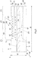
- Fig. 1 schematically is a sectional view through a designed as a security document 2 security item 1 is shown.
- the security document 2 comprises a document body 10. In the illustrated embodiment, this is designed as a lamination body 100.
- the document body 10 has an upper side 11 and an opposite lower side 12.
- the document body 10 is formed flat, which means that an edge length 30 of the top 11 is greater, preferably by an order of magnitude greater than a distance between the top and bottom, ie a document body thickness 40.
- the document body 10 is formed in the illustrated embodiment from the top 11 to the bottom 12 of five material layers, which are joined together in a lamination process to the lamination body 100. From the upper side 11 to the lower side 12, these are a transparent material layer 110, a first laser-transparent material layer 120, an opaque material layer 130 with a recess 135 which is filled with a transparent material 136, a second laser-capable substrate layer 140 and a further transparent layer 150 Other embodiments may include a different number of layers of material. It is essential that at least one material layer in the volume is opaque and this has a recess which is filled with a transparent material. In this Area or section all above and below arranged material layers are transparent in volume.
- the document body 10 has a window section 280, in which all material layers 110 to 150 between the upper side 11 and the lower side 12 are all made transparent in the volume.
- the document body 10 has a supervision section 270, in which a material layer, in the illustrated embodiment, the material layer 130, is made opaque in volume.
- a material layer in the illustrated embodiment, the material layer 130
- the window section 280 information is also recorded, which are stored in the entire volume between the top 11 and the bottom 12 in the region of the window portion 280.
- the window portion 280 and the supervisor portion 270 immediately adjoin one another along a portion boundary 290.
- the document body 10 further includes a microlens array 300 having a plurality of lens elements 310.
- the lens array 300 has a plurality of similarly formed cylindrical lens elements 310.
- the lens array 300 extends to one part 320 via the overhead section 270 and to another part 330 via the window section 280 of the document body.
- the lens array 300 thus extends over a section boundary 290 between the supervisor section 270 and the window section 280.
- upper side 11 and lower side 12 are always chosen here with respect to the document body 10 such that the microlens array 300 is formed on or in the upper side 11 of the document body 10. The terms do not give any information with regard to a later use.
- the page which is essential for the use can therefore also serve as the underside 12 of the document body 10.
- a viewing or Er chargeds therapiesspine first information In the document body 10 is additionally stored a viewing or Er chargeds therapiesspare first information.
- This storage takes place in the document body 10 via first irreversible material changes 411. These are shown schematically in the illustrated figure, each by the lower case letter "a”.
- the storage takes place, for example, by irradiating along a direction 601, which also corresponds to a viewing direction for recognizing the first information, the first information through the lens array into the security document.
- the material thicknesses of the transparent material layer 110 and of the first laser-capable material layer 120 are preferably selected such that focus positions of the lens elements 310 of the lens array 300 lie in the first laser-sensitive material layer 120.
- a spatial light modulator which may be formed, for example, as a unit of liquid crystal cells with polarization filters.
- the spatially modulated light is focused by the lens elements 310 of the microlens in each case in focus positions and chosen in terms of intensity so that in the focus positions irreversible material changes, such as blackening, are performed. Since the blackening is effected only in the focus positions, the stored first information can be seen from the first direction 601.
- the blackening formed in the focus points, which correspond to the first information, is reimaged to a viewer. From other deviating directions, however, other areas of the laser-sensitive material layer are shown on which there is no blackening.
- the first information is stored in the document body 10 depending on the viewing direction.
- a second information 420 about second irreversible material changes 421 is stored, which are represented by the uppercase letter "A".
- the second information is designed as static information, i. stored so that it can be detected from all viewing directions through the top 11. This can be effected by introducing the second information into the document body 10, for example via a laser marking, through the underside 12 of the document body 10.
- laser radiation is spatially modulated with the second information and focused so that the largest energy density preferably occurs in the second laser-sensitive material layer, so that the second information on the second irreversible material changes 421 is stored in the second laser-sensitive material layer 140.
- the first information 410 and the second information 420 are matched to one another such that from the one viewing direction 601, from which the first information 410 can be detected, the first information 410 and the second information 420 supplement to a total information 430.
- the first information may be "aaa” and the second information is "A”. The total information is then "aaaAaaa”.
- the second information 420 provides a part of the total information 430, which is fitted in the first information 410 at a predetermined position.
- the first information 410 may consist of a sequence of numbers "123 567" and the second information of the number "4". The total information is then the sequence "1234567".
- the overall information is chosen so that it has a meaning that can be easily checked by a viewer.
- the information content of the overall information may be formed once more for example as a print or laser mark at another location in the security document for reference purposes as reference information 450.
- the first and the second information are positioned relative to each other so that a subsequent falsification of components of the first or the second information is easily recognizable.
- the first information and the second information are each formed from alphanumeric characters of the same character set and the same font size.
- the second information comprises one or more alphanumeric characters which, when viewed from the direction 601 from which the first information is detectable, insert into the latter such that the characters are correctly aligned with one another.
- the first information 410 always extends over both the supervision section 270 and the window section 280.
- the first information 410 has components 415 that are stored in the window section 280 and components 416 that are stored in the supervision section 270 , Embodiments in which at least a portion of the second information immediately adjacent to the section boundary 290 is formed to fit into the first information formed across the section boundary 290 are particularly difficult to forge.
- FIG. 2 is a schematic plan view of a security document 2 similar to that of FIG Fig. 1 shown.
- the same technical features are identified in all figures with the same reference numerals.
- the first information 410 for vertical viewing through the microlens array in the Document body 10 is stored. This means that in top view both the first information and the second information are visible.
- the microlens array 300 is both partially over the supervisor portion 270 and partially over the window portion 280 and spans the portion boundary 290.
- the first information 410 "123 567" is partially formed in the supervision section 270 and partially in the window section 280 and thus also spans the section boundary 290.
- the second information 420 "IV” is fitted in the first information 410 so that the first information 410 and the second information 420 to the overall information 430 "123IV567".
- Their information content is once again stored as reference information 450 in the security document, for example as a laser engraving elsewhere.
- the reference information 450 could also be formed as an imprint on the opaque material layer. It would also be possible to store this information in a hologram and / or in a chip, which optionally can also be integrated into the security document and are not shown here for reasons of simplification.
- the Roman notation of number 4 "IV” is chosen here only to indicate that this number is not directionally stored by the subpage as second information 420.
- FIG. 12 is a view from another viewing direction through the top of the security document analogous to that of FIG Fig. 2 shown. It can be clearly seen that only the second information and the reference information 450 can be detected. The viewing direction-dependent first information can not be detected from this detection or viewing direction.
- a further embodiment of a security document 2 with a document body 10 is shown.
- the second laser-able material layer is missing, so that the second information 420 is likewise stored in the first laser-able material layer 120. This is done as in the embodiment of the Fig. 1 and 2 by an irradiation of focused laser light through the underside 12 of the document body 10.
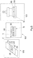
- Fig. 5 1 schematically shows the production of a security object 1 in the form of a document body 10 in the form of a lamination body 100.
- substrate layers 210 to 250 are compiled, which with the material layers 110 to 150 of the embodiment of Fig. 1 correspond. This means that a transparent substrate layer 250, a first laser-capable transparent substrate layer 220, an opaque substrate layer 230 with a recess 235 and a transparent insert 238 filling this recess 235, a second laser-capable substrate layer 240 and a further transparent substrate layer 250 are gathered in a gathering station 1010 become.
- the thus-formed substrate layers 210 to 250 are assembled in a lamination station 1020 into a document body 10 which is formed as a lamination body 100.
- the microlens array 300 is embossed in the upper side 11 of the document body 10 formed.
- the embossing is effected such that the structuring of the microlenses does not protrude beyond a top plane 21 of the top 11, which is defined by those portions of the top 11 in which the microlens array 300 is not formed.
- Such an embodiment protects the individual lens elements 310 of the microlens array 300 from damage.
- the lamination body 100 thus produced is then placed in a marking device 1030.
- the document body 10 is held in a holder 1110.
- the marking is based on Fig. 6 explained.
- the holder 1110 is pivotable about a pivot axis 1120.
- the document body 10 is arranged in the holder 1110 so that the pivot axis 1120 is formed parallel to longitudinal directions of extension of the lens elements 310, which are formed as cylindrical lenses, of the microlens array 300. Since the microlens array 300 is not necessarily centered on top of the document body 10, the pivot axis 1120 typically does not coincide with a central axis 350 of the lens array. In addition, slight manufacturing tolerances occur in the formation of the window portion and the relative positioning of the microlens array relative to the window portion and the portion boundary, respectively.
- the marking device 1030 has a camera 1130. This is opposite a transmitted light source 1140 is arranged. The light of this transmitted light source passes through the window portion 280 of the document body 10 and is detected by the camera 1130. A detected view shows such a transmitted light view 1141 of the document body 10.
- the window section 280 as a bright area and the supervisory section 270 as a dark area are clearly recognizable. As a result, the exact position of the boundary portion 290, which does not necessarily have to be rectilinear, can be determined.
- a grazing light source 1150 is provided.
- a grazing light view 1151 detected by the camera 1130 shows a clear contrast between the lens array 300 and the remaining surface 14 of the upper side. This makes it possible to also determine the position of the lens array 300 precisely.
- the marking process is controlled by a controller 1200.
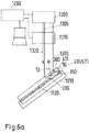
- Fig. 6a the situation for marking the first information is shown schematically.
- the first information stored for a viewing direction dependency is stored for a detection direction which does not coincide with a surface normal 13 of the top 11 of the document body 10. Therefore, the document body 10 in the holder 1110 is usually pivoted by an angle ⁇ with respect to a light incident direction 1320.
- Incident light 1305 of a marker light source 1300 which is formed, for example, as a laser light source, is modulated in a spatial light modulator 1310 according to the first information.
- the first information is impressed on the light. Only at every point where an irreversible material change 411 is to be induced in the security document, light is transmitted through the spatial light modulator 1310, in other places it is blocked.
- Fig. 6b is the document body 10 tilted by an angle - ⁇ with respect to the light incident direction with the top.
- a third information is preferably stored in the document body.
- the first information 410 and the third information 440 which are visible under different viewing directions.
- the document body is pivoted by 180 ° relative to the light incident direction, so that a marking takes place through the bottom 12.
- the second information 420 is introduced in a positionally matched manner to the first information 410, so that preferably the first information and the second information supplement one another with overall information.
- the third information can also be designed so that it complements with the second information to a further overall information.
- the overall information and the further overall information are preferably, for example, as printed information, for example, on the substrate layer 230 (see FIG. Fig. 4 ) are printed before the lamination and can serve as reference information and further reference information that can be seen in the finished document body 10 on the material layer 130 as a print.
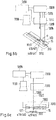
- Fig. 7a to 7d are views of a designed as a security document 2 security article 1, which are prepared according to the method described above, shown schematically.
- the first information 410 "123 567” is detectable together with the second 420 "IV” information.
- the first reference information 451 "123IV567” and the second reference information 452 "765IV321” are detectable. If the first and second information 410, 420 are not precisely positioned relative to one another, this is visible to a viewer.
- a boundary distance 550 of the second information 420 from the boundary section 290 is preferably smaller than a character length 551 of the string of the first information 410.
- Fig. 7b For example, the view is shown under a viewing direction - ⁇ with respect to the surface normal.
- the third information 440 "765 321" together with the second information 420 “IV” and again the reference information 451, 452.
- Fig. 7c a vertical plan view of the security document 2 is shown. From this viewing direction, only the second information 420 "IV" can be recognized together with the reference information 451, 452. When viewed through the bottom 12, which in Fig. 7d is shown, only the second information 420 mirror-inverted "VI" to recognize.
- the reference information can not be seen when viewed from this bottom 12 because the opaque material layer prevents the document body 10 from looking through those locations 461, 462 where the reference information should be visible.
- the first and the second information are additionally linked in terms of information technology, for example, the second information may represent a check or checksum of the alphanumeric characters of the first information.
- the third information may be selected and linked to the second information in the same way.
- fourth information may also be associated, which is likewise linked by the underside of the document body as static information stored via irreversible changes.
Landscapes
- Engineering & Computer Science (AREA)
- Manufacturing & Machinery (AREA)
- Physics & Mathematics (AREA)
- Health & Medical Sciences (AREA)
- Electromagnetism (AREA)
- General Health & Medical Sciences (AREA)
- Toxicology (AREA)
- Business, Economics & Management (AREA)
- Accounting & Taxation (AREA)
- Finance (AREA)
- Credit Cards Or The Like (AREA)
- Laser Beam Processing (AREA)
- Lenses (AREA)
Priority Applications (1)
| Application Number | Priority Date | Filing Date | Title |
|---|---|---|---|
| PL17708785T PL3423286T3 (pl) | 2016-03-04 | 2017-03-03 | Przedmiot zabezpieczony z dynamiczną i statyczną okienkową cechą zabezpieczającą oraz sposób jego wytwarzania |
Applications Claiming Priority (2)
| Application Number | Priority Date | Filing Date | Title |
|---|---|---|---|
| DE102016203609.2A DE102016203609A1 (de) | 2016-03-04 | 2016-03-04 | Sicherheitsgegenstand mit dynamischem und statischem Fenstersicherheitsmerkmal und Verfahren zur Herstellung |
| PCT/EP2017/055099 WO2017149153A1 (de) | 2016-03-04 | 2017-03-03 | Sicherheitsgegenstand mit dynamischem und statischem fenstersicherheitsmerkmal und verfahren zur herstellung |
Publications (2)
| Publication Number | Publication Date |
|---|---|
| EP3423286A1 EP3423286A1 (de) | 2019-01-09 |
| EP3423286B1 true EP3423286B1 (de) | 2019-08-07 |
Family
ID=58228145
Family Applications (1)
| Application Number | Title | Priority Date | Filing Date |
|---|---|---|---|
| EP17708785.5A Active EP3423286B1 (de) | 2016-03-04 | 2017-03-03 | Sicherheitsgegenstand mit dynamischem und statischem fenstersicherheitsmerkmal und verfahren zur herstellung |
Country Status (9)
| Country | Link |
|---|---|
| US (1) | US10800201B2 (da) |
| EP (1) | EP3423286B1 (da) |
| CN (1) | CN109070621B (da) |
| AU (1) | AU2017228040B2 (da) |
| DE (1) | DE102016203609A1 (da) |
| DK (1) | DK3423286T3 (da) |
| ES (1) | ES2748127T3 (da) |
| PL (1) | PL3423286T3 (da) |
| WO (1) | WO2017149153A1 (da) |
Families Citing this family (11)
| Publication number | Priority date | Publication date | Assignee | Title |
|---|---|---|---|---|
| EP3584091B1 (en) * | 2017-02-16 | 2024-01-31 | Dai Nippon Printing Co., Ltd. | Information page |
| GB2584552B (en) * | 2017-10-19 | 2021-07-21 | De La Rue Int Ltd | Security devices, security articles, security documents and methods for their manufacture |
| GB2570434B (en) * | 2017-10-19 | 2021-10-13 | De La Rue Int Ltd | Security documents and methods of manufacture thereof |
| CN109975886B (zh) * | 2019-04-30 | 2024-08-06 | 广东太微加速器有限公司 | 一种中子安检设备 |
| GB2592235B (en) | 2020-02-20 | 2023-02-01 | De La Rue Int Ltd | A security sheet |
| DE102020212977A1 (de) | 2020-10-14 | 2022-04-14 | Bundesdruckerei Gmbh | Sicherheitselement mit Fensterausleger und Verfahren zur Herstellung |
| DE102021002214A1 (de) | 2021-04-27 | 2022-10-27 | Giesecke+Devrient Mobile Security Gmbh | Sicherheitsmerkmal für ein Wertdokument, Wertdokument und Verfahren zur Herstellung eines Sicherheitsmerkmals |
| DE102021002225A1 (de) * | 2021-04-27 | 2022-10-27 | Giesecke+Devrient Mobile Security Gmbh | Sicherheitsmerkmal für ein Wertdokument, Wertdokument und Verfahren zur Herstellung eines Sicherheitsmerkmals |
| DE102021114246A1 (de) | 2021-06-01 | 2022-12-01 | Bundesdruckerei Gmbh | Karte und Verfahren zur Herstellung einer Karte |
| FR3124000B1 (fr) * | 2021-06-15 | 2023-06-09 | Idemia France | Formation d’une image 3D à partir d’une structure lenticulaire |
| EP4552856A1 (en) * | 2023-11-09 | 2025-05-14 | HID Global CID SAS | Personalizable security document and method of manufacturing the same |
Family Cites Families (28)
| Publication number | Priority date | Publication date | Assignee | Title |
|---|---|---|---|---|
| EP0216947B1 (de) | 1985-10-01 | 1991-01-02 | Maurer Electronics Gmbh | Kartenförmiger Datenträger und Verfahren zu seiner Herstellung |
| EP0219012B1 (de) * | 1985-10-15 | 1993-01-20 | GAO Gesellschaft für Automation und Organisation mbH | Datenträger mit einem optischen Echtheitsmerkmal sowie Verfahren zur Herstellung und Prüfung des Datenträgers |
| DE4243987C2 (de) | 1992-12-23 | 2003-10-09 | Gao Ges Automation Org | Ausweiskarten mit visuell sichtbarem Echtheitsmerkmal |
| PT1322480E (pt) | 2000-10-05 | 2007-01-31 | Trub Ag | Suporte de gravação |
| NL1022766C2 (nl) | 2003-02-24 | 2004-09-21 | Enschede Sdu Bv | Identiteitskaart alsmede reisdocument. |
| DE10358784A1 (de) | 2003-12-12 | 2005-07-14 | Giesecke & Devrient Gmbh | Datenträger mit mittels Laserstrahl eingeschriebenen Kennzeichnungen und Verfahren zu seiner Herstellung |
| DE102005007749A1 (de) * | 2005-02-18 | 2006-08-31 | Giesecke & Devrient Gmbh | Sicherheitselement und Verfahren zu seiner Herstellung |
| DE102005028162A1 (de) | 2005-02-18 | 2006-12-28 | Giesecke & Devrient Gmbh | Sicherheitselement und Verfahren zu seiner Herstellung |
| US20060197337A1 (en) | 2005-03-04 | 2006-09-07 | Canadian Bank Note Company, Limited | Identification document with lenticular watermark |
| CN101443692B (zh) * | 2006-05-12 | 2012-11-21 | 克瑞尼股份有限公司 | 微型光学膜结构、安全文件或标签及其鉴定方法 |
| DE102008008044B4 (de) | 2008-02-05 | 2022-09-22 | Bundesdruckerei Gmbh | Verfahren zum Prägen von Oberflächenstrukturen in einem Substrat zur Herstellung eines kartenförmigen Datenträgers |
| DE102008031653A1 (de) | 2008-07-03 | 2010-01-14 | Bundesdruckerei Gmbh | Verfahren und Vorrichtung zum Einbringen eines Sicherheitsmerkmals in ein Wert-oder Sicherheitsdokument |
| EP2199099A1 (en) | 2008-12-18 | 2010-06-23 | Gemalto Oy | Identification document with an improved anti-counterfeiting element |
| GB0919108D0 (en) | 2009-10-30 | 2009-12-16 | Rue De Int Ltd | Security device |
| DE102010048772A1 (de) | 2010-10-13 | 2012-04-19 | Bundesdruckerei Gmbh | Verfahren zum Herstellen eines Sicherheitsdokuments mit einem betrachtungswinkelabhängigen Sicherheitsmerkmal sowie Sicherheitsdokument |
| DE102010062046A1 (de) * | 2010-11-26 | 2012-05-31 | Bundesdruckerei Gmbh | Wert- und/oder Sicherheitsdokument mit farbigem Durchsichtsicherheitsmerkmal und Verfahren zu dessen Herstellung |
| DE102011004935A1 (de) | 2011-03-01 | 2012-09-06 | Bundesdruckerei Gmbh | Verbundkörper und Verfahren zur Herstellung eines Verbundkörpers mit einem innenliegenden Sicherheitsmerkmal |
| PL2559563T3 (pl) | 2011-08-18 | 2014-10-31 | Polska Wytwornia Papierow Wartosciowych S A | Dokument zabezpieczony z efektem przeziernym i sposoby jego wytwarzania i weryfikacji |
| DE102012204340A1 (de) | 2012-03-19 | 2013-09-19 | Bundesdruckerei Gmbh | Sicherheitsdokument mit einem Perforationsfenster und Verfahren zu dessen Herstellung |
| DE102012204341A1 (de) | 2012-03-19 | 2013-09-19 | Bundesdruckerei Gmbh | Verfahren zur Herstellung eines Sicherheitsverbundkörpers und Sicherheitsverbundkörper mit innenliegender brechender Struktur |
| DE102012018774A1 (de) | 2012-09-24 | 2014-03-27 | Giesecke & Devrient Gmbh | Sicherheitselement mit Darstellungsanordnung |
| DE102012025262B4 (de) | 2012-12-21 | 2020-06-04 | Giesecke+Devrient Currency Technology Gmbh | Verfahren zur Herstellung eines Sicherheitselementes |
| DE102012025264B4 (de) | 2012-12-21 | 2020-06-04 | Giesecke+Devrient Currency Technology Gmbh | Verfahren zur Herstellung eines Sicherheitselementes |
| DE102014100532A1 (de) * | 2014-01-17 | 2015-07-23 | Bundesdruckerei Gmbh | Verfahren zum Überprüfen der Echtheit eines Identifikationsdokumentes |
| EP4582263A1 (en) | 2014-07-17 | 2025-07-09 | Visual Physics, LLC | An improved polymeric sheet material for use in making polymeric security documents such as banknotes |
| GB2559140B (en) | 2014-07-30 | 2020-09-02 | Canadian Bank Note Co Ltd | Security document having a protected window and method for making the same |
| DE102014015280A1 (de) | 2014-10-16 | 2016-04-21 | Giesecke & Devrient Gmbh | Tragbarer Datenträger |
| AU2015100387B4 (en) * | 2015-03-26 | 2015-10-29 | Ccl Secure Pty Ltd | A Security Document or Token |
-
2016
- 2016-03-04 DE DE102016203609.2A patent/DE102016203609A1/de not_active Withdrawn
-
2017
- 2017-03-03 AU AU2017228040A patent/AU2017228040B2/en active Active
- 2017-03-03 PL PL17708785T patent/PL3423286T3/pl unknown
- 2017-03-03 DK DK17708785.5T patent/DK3423286T3/da active
- 2017-03-03 EP EP17708785.5A patent/EP3423286B1/de active Active
- 2017-03-03 CN CN201780027418.3A patent/CN109070621B/zh active Active
- 2017-03-03 ES ES17708785T patent/ES2748127T3/es active Active
- 2017-03-03 US US16/082,135 patent/US10800201B2/en active Active
- 2017-03-03 WO PCT/EP2017/055099 patent/WO2017149153A1/de not_active Ceased
Non-Patent Citations (1)
| Title |
|---|
| None * |
Also Published As
| Publication number | Publication date |
|---|---|
| AU2017228040A1 (en) | 2018-10-04 |
| EP3423286A1 (de) | 2019-01-09 |
| PL3423286T3 (pl) | 2020-01-31 |
| CN109070621A (zh) | 2018-12-21 |
| DE102016203609A1 (de) | 2017-09-07 |
| DK3423286T3 (da) | 2019-09-30 |
| WO2017149153A1 (de) | 2017-09-08 |
| ES2748127T3 (es) | 2020-03-13 |
| AU2017228040B2 (en) | 2019-07-25 |
| US20190283482A1 (en) | 2019-09-19 |
| CN109070621B (zh) | 2021-01-15 |
| US10800201B2 (en) | 2020-10-13 |
Similar Documents
| Publication | Publication Date | Title |
|---|---|---|
| EP3423286B1 (de) | Sicherheitsgegenstand mit dynamischem und statischem fenstersicherheitsmerkmal und verfahren zur herstellung | |
| EP2867031B1 (de) | Sicherheitselement mit beugungsstrukturen aufweisenden mikrostrukturen sowie verfahren zur herstellung und verifikation | |
| EP1697146B1 (de) | Datenträger mit mittels laserstrahl eingeschriebenen kennzeichnungen und verfahren zu seiner herstellung | |
| EP2627517B1 (de) | Verfahren zum herstellen eines sicherheitsdokuments mit einem betrachtungswinkelabhängigen sicherheitsmerkmal | |
| EP2828093B1 (de) | Sicherheitsdokument mit einem perforationsfenster und verfahren zu dessen herstellung | |
| DE102012211767B4 (de) | Sicherheitsdokumentenrohling für eine farbige Laserpersonalisierung, Verfahren zur Herstellung eines Sicherheitsdokuments mittels farbiger Laserpersonalisierung eines Sicherheitsdokumentenrohlings und Sicherheitsdokument. | |
| DE112017001245T5 (de) | Mikrooptische Vorrichtung mit Struktur mit integriertem Fokussierungselement und Bildelement | |
| DE102013007484A1 (de) | Optisch variables Sicherheitselement | |
| EP2828095B1 (de) | Verfahren zur herstellung eines sicherheitsverbundkörpers und sicherheitsverbundkörper mit innenliegender brechender struktur | |
| EP1983473A1 (de) | Datenträger mit Kennzeichnungen | |
| EP2934903B1 (de) | Sicherheitsmerkmal für ein wert- und/oder sicherheitsprodukt, das sicherheitsmerkmal aufweisendes wert- und/oder sicherheitsprodukt und verfahren zum herstellen des sicherheitsmerkmals | |
| WO2001029764A1 (de) | Datenträger mit echtheitsmerkmalen und herstellverfahren hierfür | |
| WO2017032450A1 (de) | Mehrschichtiger datenträger mit flächigem durchsichtsfenster | |
| EP2828094B1 (de) | Verfahren zur herstellung eines sicherheitsverbundkörpers und sicherheitsverbundkörper mit zwei optisch brechenden strukturen | |
| DE112014001682T5 (de) | Linsenfolienbasierte Sicherheitsvorrichtung | |
| EP4037914B1 (de) | Personalisierung einer mehrzahl von sicherheitselementen | |
| EP2875963B1 (de) | Sicherheitsdokument mit biegesicherheitsmerkmal | |
| DE112015001463T5 (de) | Volumenhologramme für Sicherheitsdokumente | |
| DE102021002214A1 (de) | Sicherheitsmerkmal für ein Wertdokument, Wertdokument und Verfahren zur Herstellung eines Sicherheitsmerkmals | |
| EP2054845B1 (de) | Kartenförmiger datenträger und verfahren zum aufzeichnen von information auf einen derartigen datenträger |
Legal Events
| Date | Code | Title | Description |
|---|---|---|---|
| STAA | Information on the status of an ep patent application or granted ep patent |
Free format text: STATUS: UNKNOWN |
|
| STAA | Information on the status of an ep patent application or granted ep patent |
Free format text: STATUS: THE INTERNATIONAL PUBLICATION HAS BEEN MADE |
|
| PUAI | Public reference made under article 153(3) epc to a published international application that has entered the european phase |
Free format text: ORIGINAL CODE: 0009012 |
|
| STAA | Information on the status of an ep patent application or granted ep patent |
Free format text: STATUS: REQUEST FOR EXAMINATION WAS MADE |
|
| 17P | Request for examination filed |
Effective date: 20181002 |
|
| AK | Designated contracting states |
Kind code of ref document: A1 Designated state(s): AL AT BE BG CH CY CZ DE DK EE ES FI FR GB GR HR HU IE IS IT LI LT LU LV MC MK MT NL NO PL PT RO RS SE SI SK SM TR |
|
| AX | Request for extension of the european patent |
Extension state: BA ME |
|
| GRAP | Despatch of communication of intention to grant a patent |
Free format text: ORIGINAL CODE: EPIDOSNIGR1 |
|
| STAA | Information on the status of an ep patent application or granted ep patent |
Free format text: STATUS: GRANT OF PATENT IS INTENDED |
|
| DAV | Request for validation of the european patent (deleted) | ||
| DAX | Request for extension of the european patent (deleted) | ||
| INTG | Intention to grant announced |
Effective date: 20190506 |
|
| GRAS | Grant fee paid |
Free format text: ORIGINAL CODE: EPIDOSNIGR3 |
|
| GRAA | (expected) grant |
Free format text: ORIGINAL CODE: 0009210 |
|
| STAA | Information on the status of an ep patent application or granted ep patent |
Free format text: STATUS: THE PATENT HAS BEEN GRANTED |
|
| AK | Designated contracting states |
Kind code of ref document: B1 Designated state(s): AL AT BE BG CH CY CZ DE DK EE ES FI FR GB GR HR HU IE IS IT LI LT LU LV MC MK MT NL NO PL PT RO RS SE SI SK SM TR |
|
| REG | Reference to a national code |
Ref country code: GB Ref legal event code: FG4D Free format text: NOT ENGLISH |
|
| REG | Reference to a national code |
Ref country code: AT Ref legal event code: REF Ref document number: 1163235 Country of ref document: AT Kind code of ref document: T Effective date: 20190815 Ref country code: CH Ref legal event code: EP |
|
| REG | Reference to a national code |
Ref country code: DE Ref legal event code: R096 Ref document number: 502017001990 Country of ref document: DE |
|
| REG | Reference to a national code |
Ref country code: IE Ref legal event code: FG4D Free format text: LANGUAGE OF EP DOCUMENT: GERMAN |
|
| REG | Reference to a national code |
Ref country code: DK Ref legal event code: T3 Effective date: 20190927 |
|
| REG | Reference to a national code |
Ref country code: NL Ref legal event code: FP |
|
| REG | Reference to a national code |
Ref country code: SE Ref legal event code: TRGR Ref country code: CH Ref legal event code: NV Representative=s name: VALIPAT S.A. C/O BOVARD SA NEUCHATEL, CH |
|
| REG | Reference to a national code |
Ref country code: NO Ref legal event code: T2 Effective date: 20190807 |
|
| REG | Reference to a national code |
Ref country code: LT Ref legal event code: MG4D |
|
| REG | Reference to a national code |
Ref country code: GR Ref legal event code: EP Ref document number: 20190403003 Country of ref document: GR Effective date: 20200122 |
|
| PG25 | Lapsed in a contracting state [announced via postgrant information from national office to epo] |
Ref country code: FI Free format text: LAPSE BECAUSE OF FAILURE TO SUBMIT A TRANSLATION OF THE DESCRIPTION OR TO PAY THE FEE WITHIN THE PRESCRIBED TIME-LIMIT Effective date: 20190807 Ref country code: HR Free format text: LAPSE BECAUSE OF FAILURE TO SUBMIT A TRANSLATION OF THE DESCRIPTION OR TO PAY THE FEE WITHIN THE PRESCRIBED TIME-LIMIT Effective date: 20190807 Ref country code: PT Free format text: LAPSE BECAUSE OF FAILURE TO SUBMIT A TRANSLATION OF THE DESCRIPTION OR TO PAY THE FEE WITHIN THE PRESCRIBED TIME-LIMIT Effective date: 20191209 Ref country code: LT Free format text: LAPSE BECAUSE OF FAILURE TO SUBMIT A TRANSLATION OF THE DESCRIPTION OR TO PAY THE FEE WITHIN THE PRESCRIBED TIME-LIMIT Effective date: 20190807 Ref country code: BG Free format text: LAPSE BECAUSE OF FAILURE TO SUBMIT A TRANSLATION OF THE DESCRIPTION OR TO PAY THE FEE WITHIN THE PRESCRIBED TIME-LIMIT Effective date: 20191107 |
|
| PG25 | Lapsed in a contracting state [announced via postgrant information from national office to epo] |
Ref country code: IS Free format text: LAPSE BECAUSE OF FAILURE TO SUBMIT A TRANSLATION OF THE DESCRIPTION OR TO PAY THE FEE WITHIN THE PRESCRIBED TIME-LIMIT Effective date: 20191207 Ref country code: RS Free format text: LAPSE BECAUSE OF FAILURE TO SUBMIT A TRANSLATION OF THE DESCRIPTION OR TO PAY THE FEE WITHIN THE PRESCRIBED TIME-LIMIT Effective date: 20190807 Ref country code: LV Free format text: LAPSE BECAUSE OF FAILURE TO SUBMIT A TRANSLATION OF THE DESCRIPTION OR TO PAY THE FEE WITHIN THE PRESCRIBED TIME-LIMIT Effective date: 20190807 Ref country code: AL Free format text: LAPSE BECAUSE OF FAILURE TO SUBMIT A TRANSLATION OF THE DESCRIPTION OR TO PAY THE FEE WITHIN THE PRESCRIBED TIME-LIMIT Effective date: 20190807 |
|
| REG | Reference to a national code |
Ref country code: ES Ref legal event code: FG2A Ref document number: 2748127 Country of ref document: ES Kind code of ref document: T3 Effective date: 20200313 |
|
| PG25 | Lapsed in a contracting state [announced via postgrant information from national office to epo] |
Ref country code: TR Free format text: LAPSE BECAUSE OF FAILURE TO SUBMIT A TRANSLATION OF THE DESCRIPTION OR TO PAY THE FEE WITHIN THE PRESCRIBED TIME-LIMIT Effective date: 20190807 |
|
| PG25 | Lapsed in a contracting state [announced via postgrant information from national office to epo] |
Ref country code: EE Free format text: LAPSE BECAUSE OF FAILURE TO SUBMIT A TRANSLATION OF THE DESCRIPTION OR TO PAY THE FEE WITHIN THE PRESCRIBED TIME-LIMIT Effective date: 20190807 Ref country code: RO Free format text: LAPSE BECAUSE OF FAILURE TO SUBMIT A TRANSLATION OF THE DESCRIPTION OR TO PAY THE FEE WITHIN THE PRESCRIBED TIME-LIMIT Effective date: 20190807 |
|
| PG25 | Lapsed in a contracting state [announced via postgrant information from national office to epo] |
Ref country code: SK Free format text: LAPSE BECAUSE OF FAILURE TO SUBMIT A TRANSLATION OF THE DESCRIPTION OR TO PAY THE FEE WITHIN THE PRESCRIBED TIME-LIMIT Effective date: 20190807 Ref country code: CZ Free format text: LAPSE BECAUSE OF FAILURE TO SUBMIT A TRANSLATION OF THE DESCRIPTION OR TO PAY THE FEE WITHIN THE PRESCRIBED TIME-LIMIT Effective date: 20190807 Ref country code: SM Free format text: LAPSE BECAUSE OF FAILURE TO SUBMIT A TRANSLATION OF THE DESCRIPTION OR TO PAY THE FEE WITHIN THE PRESCRIBED TIME-LIMIT Effective date: 20190807 Ref country code: IS Free format text: LAPSE BECAUSE OF FAILURE TO SUBMIT A TRANSLATION OF THE DESCRIPTION OR TO PAY THE FEE WITHIN THE PRESCRIBED TIME-LIMIT Effective date: 20200224 |
|
| REG | Reference to a national code |
Ref country code: DE Ref legal event code: R097 Ref document number: 502017001990 Country of ref document: DE |
|
| PLBE | No opposition filed within time limit |
Free format text: ORIGINAL CODE: 0009261 |
|
| STAA | Information on the status of an ep patent application or granted ep patent |
Free format text: STATUS: NO OPPOSITION FILED WITHIN TIME LIMIT |
|
| PG2D | Information on lapse in contracting state deleted |
Ref country code: IS |
|
| 26N | No opposition filed |
Effective date: 20200603 |
|
| PG25 | Lapsed in a contracting state [announced via postgrant information from national office to epo] |
Ref country code: MC Free format text: LAPSE BECAUSE OF FAILURE TO SUBMIT A TRANSLATION OF THE DESCRIPTION OR TO PAY THE FEE WITHIN THE PRESCRIBED TIME-LIMIT Effective date: 20190807 |
|
| PG25 | Lapsed in a contracting state [announced via postgrant information from national office to epo] |
Ref country code: IE Free format text: LAPSE BECAUSE OF NON-PAYMENT OF DUE FEES Effective date: 20200303 |
|
| PG25 | Lapsed in a contracting state [announced via postgrant information from national office to epo] |
Ref country code: MT Free format text: LAPSE BECAUSE OF FAILURE TO SUBMIT A TRANSLATION OF THE DESCRIPTION OR TO PAY THE FEE WITHIN THE PRESCRIBED TIME-LIMIT Effective date: 20190807 Ref country code: CY Free format text: LAPSE BECAUSE OF FAILURE TO SUBMIT A TRANSLATION OF THE DESCRIPTION OR TO PAY THE FEE WITHIN THE PRESCRIBED TIME-LIMIT Effective date: 20190807 |
|
| P01 | Opt-out of the competence of the unified patent court (upc) registered |
Effective date: 20230530 |
|
| PG25 | Lapsed in a contracting state [announced via postgrant information from national office to epo] |
Ref country code: SI Free format text: LAPSE BECAUSE OF FAILURE TO SUBMIT A TRANSLATION OF THE DESCRIPTION OR TO PAY THE FEE WITHIN THE PRESCRIBED TIME-LIMIT Effective date: 20190807 |
|
| PGFP | Annual fee paid to national office [announced via postgrant information from national office to epo] |
Ref country code: ES Payment date: 20250416 Year of fee payment: 9 |
|
| PGFP | Annual fee paid to national office [announced via postgrant information from national office to epo] |
Ref country code: IT Payment date: 20250331 Year of fee payment: 9 |
|
| PGFP | Annual fee paid to national office [announced via postgrant information from national office to epo] |
Ref country code: CH Payment date: 20250401 Year of fee payment: 9 |
|
| PGFP | Annual fee paid to national office [announced via postgrant information from national office to epo] |
Ref country code: MK Payment date: 20250218 Year of fee payment: 9 |
|
| REG | Reference to a national code |
Ref country code: CH Ref legal event code: U11 Free format text: ST27 STATUS EVENT CODE: U-0-0-U10-U11 (AS PROVIDED BY THE NATIONAL OFFICE) Effective date: 20260401 |
|
| PGFP | Annual fee paid to national office [announced via postgrant information from national office to epo] |
Ref country code: SE Payment date: 20260323 Year of fee payment: 10 |
|
| PGFP | Annual fee paid to national office [announced via postgrant information from national office to epo] |
Ref country code: GB Payment date: 20260324 Year of fee payment: 10 |
|
| PGFP | Annual fee paid to national office [announced via postgrant information from national office to epo] |
Ref country code: DE Payment date: 20260320 Year of fee payment: 10 Ref country code: NO Payment date: 20260320 Year of fee payment: 10 Ref country code: DK Payment date: 20260323 Year of fee payment: 10 |
|
| PGFP | Annual fee paid to national office [announced via postgrant information from national office to epo] |
Ref country code: AT Payment date: 20260319 Year of fee payment: 10 |
|
| PGFP | Annual fee paid to national office [announced via postgrant information from national office to epo] |
Ref country code: LU Payment date: 20260320 Year of fee payment: 10 Ref country code: BE Payment date: 20260323 Year of fee payment: 10 |
|
| PGFP | Annual fee paid to national office [announced via postgrant information from national office to epo] |
Ref country code: NL Payment date: 20260323 Year of fee payment: 10 |
|
| PGFP | Annual fee paid to national office [announced via postgrant information from national office to epo] |
Ref country code: FR Payment date: 20260324 Year of fee payment: 10 |
|
| PGFP | Annual fee paid to national office [announced via postgrant information from national office to epo] |
Ref country code: GR Payment date: 20260319 Year of fee payment: 10 Ref country code: PL Payment date: 20260218 Year of fee payment: 10 |