EP3422886B1 - A comfort padding and a helmet comprising the comfort padding - Google Patents
A comfort padding and a helmet comprising the comfort padding Download PDFInfo
- Publication number
- EP3422886B1 EP3422886B1 EP16892828.1A EP16892828A EP3422886B1 EP 3422886 B1 EP3422886 B1 EP 3422886B1 EP 16892828 A EP16892828 A EP 16892828A EP 3422886 B1 EP3422886 B1 EP 3422886B1
- Authority
- EP
- European Patent Office
- Prior art keywords
- comfort padding
- layer
- membrane
- layers
- helmet
- Prior art date
- Legal status (The legal status is an assumption and is not a legal conclusion. Google has not performed a legal analysis and makes no representation as to the accuracy of the status listed.)
- Active
Links
Images



Classifications
-
- A—HUMAN NECESSITIES
- A42—HEADWEAR
- A42B—HATS; HEAD COVERINGS
- A42B3/00—Helmets; Helmet covers ; Other protective head coverings
- A42B3/04—Parts, details or accessories of helmets
- A42B3/06—Impact-absorbing shells, e.g. of crash helmets
- A42B3/062—Impact-absorbing shells, e.g. of crash helmets with reinforcing means
- A42B3/063—Impact-absorbing shells, e.g. of crash helmets with reinforcing means using layered structures
- A42B3/064—Impact-absorbing shells, e.g. of crash helmets with reinforcing means using layered structures with relative movement between layers
-
- A—HUMAN NECESSITIES
- A42—HEADWEAR
- A42B—HATS; HEAD COVERINGS
- A42B3/00—Helmets; Helmet covers ; Other protective head coverings
- A42B3/04—Parts, details or accessories of helmets
- A42B3/10—Linings
- A42B3/12—Cushioning devices
- A42B3/121—Cushioning devices with at least one layer or pad containing a fluid
-
- A—HUMAN NECESSITIES
- A42—HEADWEAR
- A42B—HATS; HEAD COVERINGS
- A42B3/00—Helmets; Helmet covers ; Other protective head coverings
- A42B3/04—Parts, details or accessories of helmets
- A42B3/10—Linings
- A42B3/12—Cushioning devices
- A42B3/125—Cushioning devices with a padded structure, e.g. foam
- A42B3/127—Cushioning devices with a padded structure, e.g. foam with removable or adjustable pads
Definitions
- the present invention concerns a comfort padding and a helmet comprising the comfort padding.
- the aim of the present invention is to provide a functionally effective yet cost effective way of providing increased head safety for a person carrying out any type of sport or the like needing a helmet.
- the solution according to the present invention is to provide a shearing and sliding movement closer to the person's head by having the shearing and sliding movement to occur within comfort padding instead of in the helmet.
- a helmet comprises an outer shell (although optional), an energy absorbing layer (often called a liner) and on the innermost side of the energy absorbing layer, facing the wearer, at least one comfort padding.
- the comfort padding may be one piece reaching to different positions inside the helmet or several patches at desired positions to add comfort for the wearer between the head and the energy absorbing layer, which usually is made of EPS or sometimes EPP, although other materials are conceivable, too.
- a comfort padding has an overall flat configuration in one plane. When attached in a helmet it follows the innermost surface of the helmet, which will make up a plane of shearing movement.
- Shearing movement comprises all movements roughly in the plane of the comfort padding and comprises specifically also sliding movement, all occurring within the comfort padding.
- the shearing plane may, depending on the position in the helmet and size of the comfort padding, be almost flat to curved.
- a comfort padding has usually a fabric material both at a side to be attached against the inside surface of the helmet and at a side to abut against a wearer's head. Between the fabric sides a polymer foam is provided. Comfort paddings are usually attached in a fixed yet detachable way, which may be accomplished by means of using hook and loop material, such as Velcro®.
- a comfort padding configured to be attached at an innermost surface of a helmet, which is facing a wearer's head, for providing a shearing and sliding movement in the comfort padding in response to an oblique force applied to the helmet in use.
- the comfort padding comprises a fabric or nonwoven inner and outer layer, of which at least one is stretchable, and at least two layers of membrane material between the inner and outer layer. Between the two membrane layers there is a lubricant material such as gel or liquid. At least one of the membrane layers has a low friction surface allowing for a sliding movement between at least the outer layer and the membrane material.
- a sliding movement is possible between the inner layer and the membrane layer having a low friction surface.
- the comfort padding comprises layers, seen from the inner side facing a wearer's head in use, the stretchable fabric or nonwoven material, open cell polymer foam, a membrane layer, lubricant material, another membrane layer, and the stretchable fabric or nonwoven material, provided facing the innermost surface of the helmet.
- the fabric is breathable and the polymer foam is an open cell polymer foam in order not to let the wearer become too sweaty at the comfort padding.
- the membrane layers are interconnected along the rims so as to provide a closed and fluid tight space, in between the membrane layers, comprising at least a fluid.
- the inner and outer layers may be interconnected along the rims. Preferably all the layers are interconnected along the rims.
- an extra layer of fabric or nonwoven material is positioned between the open cellular foam and the membrane layer.
- the extra layer of fabric or nonwoven material between the open cellular foam and the membrane layer has preferably a low friction surface.
- a surface configured to attach to the innermost side of a helmet is loopy or roughened in order to attach to for example hook material, such as Velcro.
- a helmet comprising
- an inventive comfort padding which has superior possibilities to handle oblique impacts due to the cooperating shearing of the gel or liquid and the sliding between at least the outer layer and membrane layer, i.e. both shearing and sliding, within the comfort padding. Since both the sliding and the shearing occurs inside the comfort padding the rotational force of the oblique impact will be handled as close to the head as possible thus limiting the torque of the head. Additionally, the comfort padding will take up radial forces, too, especially when using a gel and preferably an open cell foam.
- a comfort padding 1 is shown per se. It comprises a first layer, an outer layer 2, which is to be positioned closest to a helmet, at the innermost surface of a helmet, such as an energy absorbing layer.
- the outer layer 2 is a layer of fabric or nonwoven material and it is preferably stretchable.
- Fig. 1 also shows a second, an inner, layer 3, which is to be positioned closest to a wearer's head 16.
- this layer 3 is a layer of fabric or nonwoven material and preferably stretchable.
- the material is preferably a material which feels nice and comfortable against the skin of the wearer. It could also have wicking properties in order to lead sweat from the wearer into the material and thereafter vaporisation of the sweat.
- the two layers 2, 3 may be of the same material but not necessarily.
- a lubricant material 8 is present, such as gel or liquid, which may provide a shearing movement in reaction to an oblique force. It is preferred to use a gel.
- These membranes 5, 5' are preferably impervious to fluids.
- the edges 7 of at least the membranes 5, 5' may be fluid tight interconnected, for example by means of welding, see Fig. 4 .
- the inner and outer layers 2, 3 are also interconnected along its edges 6, although it is not necessary, as can be seen in Fig. 5-6 . All the layers and membranes may be connected in the same rim if desired (not shown).
- At least one of the membrane layers 5, 5' has a low friction surface and thus will allow for a sliding movement, between at least the outer layer 2 and the membrane layer 5, in response to an oblique impact.
- the inner membrane layer 5' has a low friction surface allowing a sliding movement between the inner layer 3 and the membrane layer 5'. Thus the sliding movement will occur within the comfort padding 1.
- a further embodiment of the comfort padding 1 is shown in cross sectional view.
- an open cell polymer layer 12 is positioned between the inner layer 3 and one of the membrane layers 5'.
- the membrane layer 5' has a low friction surface and thus will allow for a shearing movement, i.e. sliding movement, between the membrane layer 5' and the open cell polymer layer 12 in response to an oblique impact. Thus additional sliding movement will occur within the comfort padding 1.
- the open cell polymer foam will provide comfort to the wearer and also facilitate sweat vaporisation.
- Fig. 3 an additional fabric or nonwoven material layer 13 is shown. It is provided between the membrane layer 5' and the layer of open cell polymer foam 12. Also in this embodiment it is preferred that the membrane layer 5' has a low friction surface and thus will allow for a shearing movement, i.e. sliding movement, between the membrane layer 5' and the additional fabric or nonwoven material layer 13 in response to an oblique impact.
- a further embodiment of the comfort padding 1 is shown in cross sectional view.
- the two membrane layers 5, 5' are interconnected along their rims 7.
- a closed volume 8 comprising at least a lubricating fluid or gel is provided.
- the inner and outer layers 2, 3 are interconnected, too, along its edges 6, either at the same rim 7 (not shown) or at a second, outer rim 15, as shown in Fig. 5 and 6 .
- Fig. 5 and 6 two different embodiments of conceivable comfort paddings are shown.
- Fig. 7 it is shown when a helmet 9 is exposed to an oblique impact and how the comfort padding 1 may move in addition to the inner shearing and sliding movements.
- the comfort padding 1 may roll somewhat, up to the fastening/connection 15 to an innermost side 14 of an energy absorbing layer 10 of a helmet 9. It is not a sliding movement between the comfort padding 1 and the inside 14 of the energy absorbing layer 10 since the comfort padding 1 is fastened/connected to the inside 14, for example by means of Velcro.
- the connection 15 does not cover the full area of the comfort padding but instead only a portion in order to render partial rolling of the comfort padding possible.
- the comfort padding 1 may start to be torn off from the inside 14 of the energy absorbing layer 10, see also Fig. 8 . This rolling movement is possible due to the stretchable inner and outer layer 2, 3.
- the membrane layer material having a low friction surface may be any material having a coating of a low friction material or made of a material having low friction itself.
- the open cell foam may be a foam of Polyethylene (PE) or similar, having a density between 10-50 kg/m 3 .
- the low density open cell polymer foam may be a foam of Polyethylene (PE) or similar having a density between 5-40 kg/m 3 .
- the shearing movement is preferably at least 5 mm, preferably at least 5-10 mm and most preferred at least 10 mm or more.
- the inner 2 and outer layer 3 is made of a flexible and stretchable fabric or nonwoven material. It is preferably knitted and may comprise yarn of elastan, lycra, spandex, polyester or nylon.
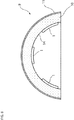
- Fig. 8 at least one comfort padding 1 of any embodiment of the present invention is provided at the innermost surface 14 of a helmet 9.
- the helmet 9 comprises an energy absorbing layer 10 and preferably an outer shell 11.
Landscapes
- Helmets And Other Head Coverings (AREA)
Description
- The present invention concerns a comfort padding and a helmet comprising the comfort padding.
- The understanding of how oblique impacts affects the brain of a person is increasingly growing and so also the different ways of taking care of oblique impacts towards helmets. Different solutions have been provided, such as having a sliding layer arranged between a shell and an energy absorbing layer, or between two energy absorbing layers. According to
EP 2440082 an attachment device for attachment to a wearer's head is provided, which is fixed to the inside of the energy absorbing layer, and where a sliding occurs between the attachment device and the inside of the energy absorbing layer. InWO2013/104073 a bladder comprising a low friction liquid or gel is shown which is provided to manage the angular forces separately from the compressive forces. The compressive forces are to be managed by the liner.WO2006/022680 shows a headband providing sliding between an inner and an outer portion around an axle provided at the sides, above the ears. - The aim of the present invention is to provide a functionally effective yet cost effective way of providing increased head safety for a person carrying out any type of sport or the like needing a helmet.
- This aim is achieved by a comfort padding as described in the
independent claim 1. - The solution according to the present invention is to provide a shearing and sliding movement closer to the person's head by having the shearing and sliding movement to occur within comfort padding instead of in the helmet. Usually a helmet comprises an outer shell (although optional), an energy absorbing layer (often called a liner) and on the innermost side of the energy absorbing layer, facing the wearer, at least one comfort padding. The comfort padding may be one piece reaching to different positions inside the helmet or several patches at desired positions to add comfort for the wearer between the head and the energy absorbing layer, which usually is made of EPS or sometimes EPP, although other materials are conceivable, too. A comfort padding has an overall flat configuration in one plane. When attached in a helmet it follows the innermost surface of the helmet, which will make up a plane of shearing movement.
- Shearing movement comprises all movements roughly in the plane of the comfort padding and comprises specifically also sliding movement, all occurring within the comfort padding. The shearing plane may, depending on the position in the helmet and size of the comfort padding, be almost flat to curved.
- A comfort padding has usually a fabric material both at a side to be attached against the inside surface of the helmet and at a side to abut against a wearer's head. Between the fabric sides a polymer foam is provided. Comfort paddings are usually attached in a fixed yet detachable way, which may be accomplished by means of using hook and loop material, such as Velcro®.
- According to a first aspect of the present invention is a comfort padding configured to be attached at an innermost surface of a helmet, which is facing a wearer's head, for providing a shearing and sliding movement in the comfort padding in response to an oblique force applied to the helmet in use. The comfort padding comprises a fabric or nonwoven inner and outer layer, of which at least one is stretchable, and at least two layers of membrane material between the inner and outer layer. Between the two membrane layers there is a lubricant material such as gel or liquid. At least one of the membrane layers has a low friction surface allowing for a sliding movement between at least the outer layer and the membrane material.
- According to an embodiment a sliding movement is possible between the inner layer and the membrane layer having a low friction surface.
- According to an embodiment the comfort padding comprises layers, seen from the inner side facing a wearer's head in use, the stretchable fabric or nonwoven material, open cell polymer foam, a membrane layer, lubricant material, another membrane layer, and the stretchable fabric or nonwoven material, provided facing the innermost surface of the helmet.
- Preferably the fabric is breathable and the polymer foam is an open cell polymer foam in order not to let the wearer become too sweaty at the comfort padding.
- According to an embodiment at least the membrane layers are interconnected along the rims so as to provide a closed and fluid tight space, in between the membrane layers, comprising at least a fluid. The inner and outer layers may be interconnected along the rims. Preferably all the layers are interconnected along the rims.
- According to an embodiment an extra layer of fabric or nonwoven material is positioned between the open cellular foam and the membrane layer. The extra layer of fabric or nonwoven material between the open cellular foam and the membrane layer has preferably a low friction surface.
- According to an embodiment a surface configured to attach to the innermost side of a helmet is loopy or roughened in order to attach to for example hook material, such as Velcro.
- According to a second aspect of the present invention a helmet is provided, comprising
- an energy absorbing layer, comprising at least one part, having an outer side facing away from a wearer's head and an innermost side facing the wearer's head,
- at least one piece of comfort padding according to the present invention, provided at the innermost side of the energy absorbing layer.
- Thus an inventive comfort padding have been provided which has superior possibilities to handle oblique impacts due to the cooperating shearing of the gel or liquid and the sliding between at least the outer layer and membrane layer, i.e. both shearing and sliding, within the comfort padding. Since both the sliding and the shearing occurs inside the comfort padding the rotational force of the oblique impact will be handled as close to the head as possible thus limiting the torque of the head. Additionally, the comfort padding will take up radial forces, too, especially when using a gel and preferably an open cell foam.
- The present invention will now be described in more detail under referral to the attached drawings, in which
-
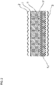
Fig. 1 shows one embodiment of a comfort padding in cross sectional view. -
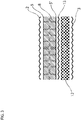
Fig. 2 shows a further embodiment of a comfort padding in cross sectional view. -
Fig. 3 shows another embodiment of a comfort padding in cross sectional view. -
Fig. 4 shows one embodiment of a comfort padding in cross sectional view having interconnected rims. -
Fig. 5 shows a cross section of an embodiment of a padding having interconnected rims. -
Fig. 6 shows a cross section of a further embodiment of a padding having interconnected rims. -
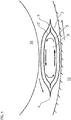
Fig. 7 shows a cross section of an embodiment of a padding during an oblique impact. -
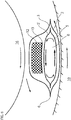
Fig. 8 shows a comfort padding in a helmet, seen in a cross sectional view. - In
Fig. 1 acomfort padding 1 is shown per se. It comprises a first layer, anouter layer 2, which is to be positioned closest to a helmet, at the innermost surface of a helmet, such as an energy absorbing layer. Theouter layer 2 is a layer of fabric or nonwoven material and it is preferably stretchable. -
Fig. 1 also shows a second, an inner,layer 3, which is to be positioned closest to a wearer'shead 16. Also thislayer 3 is a layer of fabric or nonwoven material and preferably stretchable. The material is preferably a material which feels nice and comfortable against the skin of the wearer. It could also have wicking properties in order to lead sweat from the wearer into the material and thereafter vaporisation of the sweat. The twolayers - In between the two
layers membrane material 5, 5' are provided. There between alubricant material 8 is present, such as gel or liquid, which may provide a shearing movement in reaction to an oblique force. It is preferred to use a gel. Thesemembranes 5, 5' are preferably impervious to fluids. The edges 7 of at least themembranes 5, 5' may be fluid tight interconnected, for example by means of welding, seeFig. 4 . Preferably the inner andouter layers edges 6, although it is not necessary, as can be seen inFig. 5-6 . All the layers and membranes may be connected in the same rim if desired (not shown). - At least one of the membrane layers 5, 5' has a low friction surface and thus will allow for a sliding movement, between at least the
outer layer 2 and themembrane layer 5, in response to an oblique impact. Preferably also the inner membrane layer 5' has a low friction surface allowing a sliding movement between theinner layer 3 and the membrane layer 5'. Thus the sliding movement will occur within thecomfort padding 1. - In
Fig. 2 a further embodiment of thecomfort padding 1 is shown in cross sectional view. In the present figure an opencell polymer layer 12 is positioned between theinner layer 3 and one of the membrane layers 5'. Preferably the membrane layer 5' has a low friction surface and thus will allow for a shearing movement, i.e. sliding movement, between the membrane layer 5' and the opencell polymer layer 12 in response to an oblique impact. Thus additional sliding movement will occur within thecomfort padding 1. - The open cell polymer foam will provide comfort to the wearer and also facilitate sweat vaporisation.
- In
Fig. 3 an additional fabric ornonwoven material layer 13 is shown. It is provided between the membrane layer 5' and the layer of opencell polymer foam 12. Also in this embodiment it is preferred that the membrane layer 5' has a low friction surface and thus will allow for a shearing movement, i.e. sliding movement, between the membrane layer 5' and the additional fabric ornonwoven material layer 13 in response to an oblique impact. - In
Fig. 4 a further embodiment of thecomfort padding 1 is shown in cross sectional view. In the present figure the twomembrane layers 5, 5' are interconnected along their rims 7. Thus aclosed volume 8 comprising at least a lubricating fluid or gel is provided. Preferably the inner andouter layers edges 6, either at the same rim 7 (not shown) or at a second,outer rim 15, as shown inFig. 5 and6 . - In
Fig. 5 and6 two different embodiments of conceivable comfort paddings are shown. InFig. 7 it is shown when ahelmet 9 is exposed to an oblique impact and how thecomfort padding 1 may move in addition to the inner shearing and sliding movements. Thecomfort padding 1 may roll somewhat, up to the fastening/connection 15 to aninnermost side 14 of anenergy absorbing layer 10 of ahelmet 9. It is not a sliding movement between thecomfort padding 1 and the inside 14 of theenergy absorbing layer 10 since thecomfort padding 1 is fastened/connected to the inside 14, for example by means of Velcro. For example, theconnection 15 does not cover the full area of the comfort padding but instead only a portion in order to render partial rolling of the comfort padding possible. In case the oblique impact is stronger, thecomfort padding 1 may start to be torn off from the inside 14 of theenergy absorbing layer 10, see alsoFig. 8 . This rolling movement is possible due to the stretchable inner andouter layer - As the person skilled in the art understands it is possible to mix, pick and choose from the suggested materials in any way as long it is not contradicting the present invention of a sliding movement within the comfort padding in response to an oblique impact.
- The membrane layer material having a low friction surface may be any material having a coating of a low friction material or made of a material having low friction itself.
- The open cell foam may be a foam of Polyethylene (PE) or similar, having a density between 10-50 kg/m3. The low density open cell polymer foam may be a foam of Polyethylene (PE) or similar having a density between 5-40 kg/m3.
- The shearing movement is preferably at least 5 mm, preferably at least 5-10 mm and most preferred at least 10 mm or more.
- In all shown embodiments it is preferred that the inner 2 and
outer layer 3 is made of a flexible and stretchable fabric or nonwoven material. It is preferably knitted and may comprise yarn of elastan, lycra, spandex, polyester or nylon. - In
Fig. 8 at least onecomfort padding 1 of any embodiment of the present invention is provided at theinnermost surface 14 of ahelmet 9. Thehelmet 9 comprises anenergy absorbing layer 10 and preferably anouter shell 11. - The presently described embodiments are only examples and shall not be seen as limiting the scope of the invention, which is presented in the claims.
Claims (11)
- A comfort padding, configured to be attached at an innermost surface of a helmet (9), which is facing a wearer's head (16), the comfort padding comprising a fabric or nonwoven inner (3) and outer layer (2),of which at least one is stretchable, and at least two layers (5, 5') of membrane material between the inner (3) and outer layer (2), and between the two layers (5, 5') of membrane material there is a lubricant material such as gel or liquid (8), at least one of the membrane layers (5, 5') has a low friction surface allowing for a sliding movement between at least the outer layer (2) and the membrane material (5) .
- The comfort padding according to claim 1, wherein the low friction surface of the membrane layer (5, 5') allows for a sliding movement between the inner layer (3) and the membrane layer (5').
- The comfort padding according to claim 1, wherein the lubricant material (8) is for providing a shearing movement in the comfort padding in response to an oblique force applied to the helmet in use.
- The comfort padding according to claims 1, 2 or 3, wherein the comfort padding comprises layers, seen from the inner side facing a wearer's head (16) in use, namely the stretchable fabric or nonwoven material (3), an open cell polymer foam (12), a membrane layer (5'), lubricant material (8), another membrane layer (5), and the stretchable fabric or nonwoven material (2), provided facing the innermost surface of the helmet.
- The comfort padding according to any of the previous claims, wherein at least the membrane layers (5, 5') are interconnected along rims (7) so as to provide a closed and fluid tight space, in between the membrane layers (5, 5'), comprising at least a fluid (8).
- The comfort padding according to claim 5, wherein all the layers and membranes are connected at the same rim.
- The comfort padding according to claim 5, wherein all the inner (3) and outer (2) layers are interconnected along edges (6).
- The comfort padding according to claim 4, wherein an extra layer of fabric or nonwoven material (13) is positioned between the open cellular foam (12) and the membrane layer (5').
- The comfort padding according to any one of the preceding claims, wherein a surface of the padding configured to attach to the innermost side of a helmet is loopy or roughened in order to attach to for example hook material such as Velcro.
- The comfort padding according to any one of the preceding claims, wherein the inner layer (3) of fabric or nonwoven material is a wicking material.
- A helmet, comprising
an energy absorbing layer (10), comprising at least one part, having an outer side facing away from a wearer's head (16) and an innermost side (14) facing the wearer's head (16),
at least one comfort padding according to any one of the previous claims, provided at the innermost side (14) of the energy absorbing layer.
Applications Claiming Priority (2)
| Application Number | Priority Date | Filing Date | Title |
|---|---|---|---|
| SE1650277 | 2016-03-02 | ||
| PCT/SE2016/051033 WO2017151028A1 (en) | 2016-03-02 | 2016-10-24 | A comfort padding and a helmet comprising the comfort padding |
Publications (3)
| Publication Number | Publication Date |
|---|---|
| EP3422886A1 EP3422886A1 (en) | 2019-01-09 |
| EP3422886A4 EP3422886A4 (en) | 2019-03-20 |
| EP3422886B1 true EP3422886B1 (en) | 2020-02-19 |
Family
ID=59744232
Family Applications (1)
| Application Number | Title | Priority Date | Filing Date |
|---|---|---|---|
| EP16892828.1A Active EP3422886B1 (en) | 2016-03-02 | 2016-10-24 | A comfort padding and a helmet comprising the comfort padding |
Country Status (4)
| Country | Link |
|---|---|
| US (1) | US20180303187A1 (en) |
| EP (1) | EP3422886B1 (en) |
| CN (1) | CN108882770B (en) |
| WO (1) | WO2017151028A1 (en) |
Families Citing this family (17)
| Publication number | Priority date | Publication date | Assignee | Title |
|---|---|---|---|---|
| SE541081C2 (en) | 2016-11-22 | 2019-04-02 | Poc Sweden Ab | A comfort padding and a helmet comprising the comfort padding |
| GB201719559D0 (en) * | 2017-11-24 | 2018-01-10 | Mips Ab | Connector |
| US11246369B2 (en) * | 2018-03-29 | 2022-02-15 | Specialized Bicycle Components, Inc. | Helmet pads with slip layers |
| US11517062B2 (en) * | 2018-05-15 | 2022-12-06 | Brian Timlick | Helmet with unique impact absorption and redirection features |
| TWI680727B (en) * | 2018-06-12 | 2020-01-01 | 豐閣行銷設計有限公司 | Hard hat capable of absorbing multi-directional impact |
| US20240277095A1 (en) * | 2018-06-12 | 2024-08-22 | Vog - Image Police Inc. | Safety helmet capable of absorbing multi-direction impact |
| GB201816832D0 (en) * | 2018-10-16 | 2018-11-28 | Mips Ab | Pad |
| US11766083B2 (en) | 2019-03-25 | 2023-09-26 | Tianqi Technology Co (Ningbo) Ltd | Helmet |
| GB201911794D0 (en) * | 2019-08-16 | 2019-10-02 | Mips Ab | Headgear |
| IT202000001117A1 (en) * | 2020-01-22 | 2021-07-22 | Mango Sport System S R L | PROTECTIVE HELMET |
| WO2021159119A1 (en) * | 2020-02-06 | 2021-08-12 | Weeks Bruce V | Impact absorption elements, systems, and methods of use |
| GB202009991D0 (en) * | 2020-06-30 | 2020-08-12 | Mips Ab | Pad and padding |
| WO2022066857A1 (en) * | 2020-09-24 | 2022-03-31 | Kuji Sports Co Ltd | Helmet |
| US20240260702A1 (en) * | 2021-05-18 | 2024-08-08 | Shield-X Technology Inc. | Helmet sheer layer |
| US20240057706A1 (en) * | 2022-08-22 | 2024-02-22 | Marvin R. Quezada Garcia | Disposable Helmet |
| US20240114987A1 (en) | 2022-10-11 | 2024-04-11 | Dacy Pro Limited | Energy absorbing materials, head protective gear comprising the same and method for fabricating thereof |
| IT202300015933A1 (en) | 2023-07-28 | 2025-01-28 | Plastidue S R L | HELMET PADDING ARRANGEMENT AND RELATED MANUFACTURING METHOD. |
Family Cites Families (44)
| Publication number | Priority date | Publication date | Assignee | Title |
|---|---|---|---|---|
| US3885246A (en) * | 1973-11-05 | 1975-05-27 | Minnesota Mining & Mfg | Retroreflective protective helmet |
| US4012794A (en) * | 1975-08-13 | 1977-03-22 | Tetsuo Nomiyama | Impact-absorbing helmet |
| US4354284A (en) * | 1981-01-28 | 1982-10-19 | The Regents Of The University Of Michigan | Protective liner for outdoor headgear |
| US4566137A (en) * | 1984-01-20 | 1986-01-28 | Gooding Elwyn R | Inflatable baffled liner for protective headgear and other protective equipment |
| DE4409839C2 (en) * | 1994-03-22 | 1996-05-02 | Oped Gmbh Orthopaedische Produ | Hard hat |
| FR2750017B1 (en) * | 1996-06-20 | 1998-08-07 | Sansarlat Jean Jacques | DEVICE FOR HYGIENIC PROTECTION OF THE BOTTOM OF A HEAD COVER |
| AU5909299A (en) * | 1998-09-03 | 2000-03-27 | Mike Dennis | Body-contact cushioning interface structure |
| DE69918869T2 (en) * | 1999-12-21 | 2005-07-21 | Neuroprevention Scandinavia Ab | HELMET |
| JP3765377B2 (en) * | 2000-04-04 | 2006-04-12 | 本田技研工業株式会社 | helmet |
| GB0116738D0 (en) * | 2001-07-09 | 2001-08-29 | Phillips Helmets Ltd | Protective headgear and protective armour and a method of modifying protective headgear and protective armour |
| US20110314589A1 (en) * | 2001-08-27 | 2011-12-29 | Vito Robert A | Vibration dampening material |
| US20040117896A1 (en) * | 2002-10-04 | 2004-06-24 | Madey Steven M. | Load diversion method and apparatus for head protective devices |
| US20040250340A1 (en) * | 2003-02-05 | 2004-12-16 | Dennis Piper | Protective headguard |
| US20060059606A1 (en) * | 2004-09-22 | 2006-03-23 | Xenith Athletics, Inc. | Multilayer air-cushion shell with energy-absorbing layer for use in the construction of protective headgear |
| JP2006016740A (en) * | 2004-07-05 | 2006-01-19 | Honda Motor Co Ltd | helmet |
| WO2006022680A1 (en) * | 2004-08-04 | 2006-03-02 | Full90 Sports, Inc. | Protective headguard |
| US8039078B2 (en) * | 2004-08-26 | 2011-10-18 | Intellectual Property Holdings, Llc | Energy-absorbing pads |
| US20060206994A1 (en) * | 2005-03-15 | 2006-09-21 | Artisent, Inc. | Safety helmet and components thereof |
| US7904971B2 (en) * | 2005-05-19 | 2011-03-15 | Mine Safety Appliances Company | Protective padding and protective padding systems |
| CA2647399A1 (en) * | 2007-12-17 | 2009-06-17 | Biokinetics And Associates Ltd. | Helmet fitting and impact attenuation system |
| US20090158506A1 (en) * | 2007-12-21 | 2009-06-25 | Harley-Davidson Motor Company Group, Inc. | Liner for a protective helmet |
| GB0800971D0 (en) * | 2008-01-18 | 2008-02-27 | Ayrtek Ltd | Sports helmet |
| CA2923361C (en) * | 2008-08-11 | 2018-10-09 | Greenhill Antiballistics Corporation | Composite material |
| US8524338B2 (en) * | 2009-11-16 | 2013-09-03 | 9Lives Llc | Impact energy attenuation system |
| SE534868C2 (en) * | 2010-05-07 | 2012-01-24 | Mips Ab | Helmet with sliding promoter provided at an energy absorbing bearing |
| EP2428129B1 (en) * | 2010-09-09 | 2013-04-03 | Oliver Schimpf | Protective helmet; method for preventing or reducing head injury |
| CN103635112B (en) * | 2011-02-09 | 2015-12-23 | 6D头盔有限责任公司 | Helmet omnidirectional EMS |
| US20140020158A1 (en) * | 2011-04-29 | 2014-01-23 | Roho, Inc. | Multilayer impact attenuating insert for headgear |
| US9089180B2 (en) * | 2011-09-08 | 2015-07-28 | Emerson Spalding Phipps | Protective helmet |
| US9839250B2 (en) * | 2011-09-09 | 2017-12-12 | Purdue Research Foundation | Dynamic load-absorbing materials and articles |
| US20130086733A1 (en) * | 2011-10-10 | 2013-04-11 | Intellectual Property Holdings, Llc | Helmet impact liner system |
| CA2864522C (en) * | 2012-01-12 | 2015-09-29 | University Of Ottawa | Head protection for reducing angular accelerations |
| US9572391B2 (en) * | 2012-03-30 | 2017-02-21 | Daniel Malcolm McInnis | Protective helmet and insert with concussion reduction features |
| US9700095B2 (en) * | 2012-04-25 | 2017-07-11 | PSE Technology LLC | Molded gel headgear having impact dispersing properties |
| US8613114B1 (en) * | 2012-07-25 | 2013-12-24 | 2nd Skull, LLC | Head guard |
| US9578917B2 (en) * | 2012-09-14 | 2017-02-28 | Pidyon Controls Inc. | Protective helmets |
| US9095179B2 (en) * | 2012-10-19 | 2015-08-04 | Brainguard Technologies, Inc. | Shear reduction mechanism |
| US20140250571A1 (en) * | 2013-03-08 | 2014-09-11 | Paris Allen Pippillion | Safety helmet with dynamic visual display |
| SE1351032A1 (en) * | 2013-04-19 | 2014-10-20 | Mips Ab | Connecting arrangements and helmets including such connecting arrangements |
| US20140338104A1 (en) * | 2013-05-17 | 2014-11-20 | Matscitechno Licensing Company | Helmet padding system |
| EP3041876B1 (en) * | 2013-09-04 | 2020-06-10 | Ghassan Dehni | Flexible polyurethane and polyurethane/polyorganosiloxane foam materials that absorb impact energy |
| US20150264993A1 (en) * | 2014-02-21 | 2015-09-24 | Matscitechno Licensing Company | Helmet padding system |
| JP2017507257A (en) * | 2014-03-07 | 2017-03-16 | ベル スポーツ, インコーポレイテッド | Multi-body helmet structure with integrated vent cover |
| US20150305430A1 (en) * | 2014-04-23 | 2015-10-29 | Gustavus Alston Rush | Personal Protective Equipment Liner |
-
2016
- 2016-10-24 EP EP16892828.1A patent/EP3422886B1/en active Active
- 2016-10-24 CN CN201680083106.XA patent/CN108882770B/en active Active
- 2016-10-24 WO PCT/SE2016/051033 patent/WO2017151028A1/en not_active Ceased
-
2018
- 2018-06-29 US US16/024,011 patent/US20180303187A1/en not_active Abandoned
Non-Patent Citations (1)
| Title |
|---|
| None * |
Also Published As
| Publication number | Publication date |
|---|---|
| CN108882770B (en) | 2021-10-15 |
| EP3422886A4 (en) | 2019-03-20 |
| US20180303187A1 (en) | 2018-10-25 |
| EP3422886A1 (en) | 2019-01-09 |
| WO2017151028A1 (en) | 2017-09-08 |
| CN108882770A (en) | 2018-11-23 |
Similar Documents
| Publication | Publication Date | Title |
|---|---|---|
| US20180303187A1 (en) | Comfort Padding and a Helmet Comprising The Comfort Padding | |
| US10271604B2 (en) | Comfort padding and a helmet comprising the comfort padding | |
| EP2542196B1 (en) | Ostomy device | |
| US12108825B2 (en) | Impact protection system | |
| CN107223027B (en) | Protective liner coupleable to inner surface of helmet, helmet including said liner and use thereof to reduce rotational acceleration transmitted to user | |
| CA3079284C (en) | Helmet | |
| US20090222964A1 (en) | Advanced Combat Helmet (ACH) system replacement padding system | |
| AU2020333788B2 (en) | Headgear | |
| JP2013019067A (en) | Helmet | |
| JP2009150043A (en) | Liner (lining) for protective helmet | |
| AU2018373784B2 (en) | Connector | |
| EP2709379A1 (en) | Ear appliance | |
| EP2768332B1 (en) | Neck collar | |
| EP3243398B1 (en) | Inner liner for a helmet and helmet including such an inner liner | |
| JP7456594B2 (en) | Inner for hat | |
| JP2018108201A (en) | Heating equipment | |
| HK1262692A1 (en) | A comfort padding and a helmet comprising the comfort padding | |
| HK1262692B (en) | A comfort padding and a helmet comprising the comfort padding | |
| HK40010476A (en) | A comfort padding and a helmet comprising the comfort padding | |
| HK40010476B (en) | A comfort padding and a helmet comprising the comfort padding | |
| JP2010196230A (en) | Sweat absorption volatilizing band | |
| JP7108264B2 (en) | hat | |
| JP2001089924A (en) | Helmet | |
| JP2021055236A (en) | Heat shield | |
| KR20160002185U (en) | Functional inner layer structure for helment |
Legal Events
| Date | Code | Title | Description |
|---|---|---|---|
| STAA | Information on the status of an ep patent application or granted ep patent |
Free format text: STATUS: THE INTERNATIONAL PUBLICATION HAS BEEN MADE |
|
| TPAC | Observations filed by third parties |
Free format text: ORIGINAL CODE: EPIDOSNTIPA |
|
| PUAI | Public reference made under article 153(3) epc to a published international application that has entered the european phase |
Free format text: ORIGINAL CODE: 0009012 |
|
| STAA | Information on the status of an ep patent application or granted ep patent |
Free format text: STATUS: REQUEST FOR EXAMINATION WAS MADE |
|
| 17P | Request for examination filed |
Effective date: 20180928 |
|
| AK | Designated contracting states |
Kind code of ref document: A1 Designated state(s): AL AT BE BG CH CY CZ DE DK EE ES FI FR GB GR HR HU IE IS IT LI LT LU LV MC MK MT NL NO PL PT RO RS SE SI SK SM TR |
|
| AX | Request for extension of the european patent |
Extension state: BA ME |
|
| A4 | Supplementary search report drawn up and despatched |
Effective date: 20190219 |
|
| RIC1 | Information provided on ipc code assigned before grant |
Ipc: A42B 3/06 20060101ALI20190213BHEP Ipc: A42B 3/12 20060101AFI20190213BHEP |
|
| DAV | Request for validation of the european patent (deleted) | ||
| DAX | Request for extension of the european patent (deleted) | ||
| GRAP | Despatch of communication of intention to grant a patent |
Free format text: ORIGINAL CODE: EPIDOSNIGR1 |
|
| STAA | Information on the status of an ep patent application or granted ep patent |
Free format text: STATUS: GRANT OF PATENT IS INTENDED |
|
| INTG | Intention to grant announced |
Effective date: 20190916 |
|
| GRAS | Grant fee paid |
Free format text: ORIGINAL CODE: EPIDOSNIGR3 |
|
| GRAA | (expected) grant |
Free format text: ORIGINAL CODE: 0009210 |
|
| STAA | Information on the status of an ep patent application or granted ep patent |
Free format text: STATUS: THE PATENT HAS BEEN GRANTED |
|
| AK | Designated contracting states |
Kind code of ref document: B1 Designated state(s): AL AT BE BG CH CY CZ DE DK EE ES FI FR GB GR HR HU IE IS IT LI LT LU LV MC MK MT NL NO PL PT RO RS SE SI SK SM TR |
|
| REG | Reference to a national code |
Ref country code: CH Ref legal event code: EP |
|
| REG | Reference to a national code |
Ref country code: DE Ref legal event code: R096 Ref document number: 602016030350 Country of ref document: DE |
|
| REG | Reference to a national code |
Ref country code: AT Ref legal event code: REF Ref document number: 1233948 Country of ref document: AT Kind code of ref document: T Effective date: 20200315 |
|
| REG | Reference to a national code |
Ref country code: IE Ref legal event code: FG4D |
|
| REG | Reference to a national code |
Ref country code: CH Ref legal event code: NV Representative=s name: DENNEMEYER AG, CH |
|
| REG | Reference to a national code |
Ref country code: NL Ref legal event code: MP Effective date: 20200219 |
|
| PG25 | Lapsed in a contracting state [announced via postgrant information from national office to epo] |
Ref country code: NO Free format text: LAPSE BECAUSE OF FAILURE TO SUBMIT A TRANSLATION OF THE DESCRIPTION OR TO PAY THE FEE WITHIN THE PRESCRIBED TIME-LIMIT Effective date: 20200519 Ref country code: FI Free format text: LAPSE BECAUSE OF FAILURE TO SUBMIT A TRANSLATION OF THE DESCRIPTION OR TO PAY THE FEE WITHIN THE PRESCRIBED TIME-LIMIT Effective date: 20200219 Ref country code: RS Free format text: LAPSE BECAUSE OF FAILURE TO SUBMIT A TRANSLATION OF THE DESCRIPTION OR TO PAY THE FEE WITHIN THE PRESCRIBED TIME-LIMIT Effective date: 20200219 |
|
| REG | Reference to a national code |
Ref country code: LT Ref legal event code: MG4D |
|
| PG25 | Lapsed in a contracting state [announced via postgrant information from national office to epo] |
Ref country code: HR Free format text: LAPSE BECAUSE OF FAILURE TO SUBMIT A TRANSLATION OF THE DESCRIPTION OR TO PAY THE FEE WITHIN THE PRESCRIBED TIME-LIMIT Effective date: 20200219 Ref country code: SE Free format text: LAPSE BECAUSE OF FAILURE TO SUBMIT A TRANSLATION OF THE DESCRIPTION OR TO PAY THE FEE WITHIN THE PRESCRIBED TIME-LIMIT Effective date: 20200219 Ref country code: LV Free format text: LAPSE BECAUSE OF FAILURE TO SUBMIT A TRANSLATION OF THE DESCRIPTION OR TO PAY THE FEE WITHIN THE PRESCRIBED TIME-LIMIT Effective date: 20200219 Ref country code: GR Free format text: LAPSE BECAUSE OF FAILURE TO SUBMIT A TRANSLATION OF THE DESCRIPTION OR TO PAY THE FEE WITHIN THE PRESCRIBED TIME-LIMIT Effective date: 20200520 Ref country code: BG Free format text: LAPSE BECAUSE OF FAILURE TO SUBMIT A TRANSLATION OF THE DESCRIPTION OR TO PAY THE FEE WITHIN THE PRESCRIBED TIME-LIMIT Effective date: 20200519 Ref country code: IS Free format text: LAPSE BECAUSE OF FAILURE TO SUBMIT A TRANSLATION OF THE DESCRIPTION OR TO PAY THE FEE WITHIN THE PRESCRIBED TIME-LIMIT Effective date: 20200619 |
|
| PG25 | Lapsed in a contracting state [announced via postgrant information from national office to epo] |
Ref country code: NL Free format text: LAPSE BECAUSE OF FAILURE TO SUBMIT A TRANSLATION OF THE DESCRIPTION OR TO PAY THE FEE WITHIN THE PRESCRIBED TIME-LIMIT Effective date: 20200219 |
|
| PG25 | Lapsed in a contracting state [announced via postgrant information from national office to epo] |
Ref country code: CZ Free format text: LAPSE BECAUSE OF FAILURE TO SUBMIT A TRANSLATION OF THE DESCRIPTION OR TO PAY THE FEE WITHIN THE PRESCRIBED TIME-LIMIT Effective date: 20200219 Ref country code: PT Free format text: LAPSE BECAUSE OF FAILURE TO SUBMIT A TRANSLATION OF THE DESCRIPTION OR TO PAY THE FEE WITHIN THE PRESCRIBED TIME-LIMIT Effective date: 20200712 Ref country code: SK Free format text: LAPSE BECAUSE OF FAILURE TO SUBMIT A TRANSLATION OF THE DESCRIPTION OR TO PAY THE FEE WITHIN THE PRESCRIBED TIME-LIMIT Effective date: 20200219 Ref country code: DK Free format text: LAPSE BECAUSE OF FAILURE TO SUBMIT A TRANSLATION OF THE DESCRIPTION OR TO PAY THE FEE WITHIN THE PRESCRIBED TIME-LIMIT Effective date: 20200219 Ref country code: LT Free format text: LAPSE BECAUSE OF FAILURE TO SUBMIT A TRANSLATION OF THE DESCRIPTION OR TO PAY THE FEE WITHIN THE PRESCRIBED TIME-LIMIT Effective date: 20200219 Ref country code: EE Free format text: LAPSE BECAUSE OF FAILURE TO SUBMIT A TRANSLATION OF THE DESCRIPTION OR TO PAY THE FEE WITHIN THE PRESCRIBED TIME-LIMIT Effective date: 20200219 Ref country code: SM Free format text: LAPSE BECAUSE OF FAILURE TO SUBMIT A TRANSLATION OF THE DESCRIPTION OR TO PAY THE FEE WITHIN THE PRESCRIBED TIME-LIMIT Effective date: 20200219 Ref country code: ES Free format text: LAPSE BECAUSE OF FAILURE TO SUBMIT A TRANSLATION OF THE DESCRIPTION OR TO PAY THE FEE WITHIN THE PRESCRIBED TIME-LIMIT Effective date: 20200219 Ref country code: RO Free format text: LAPSE BECAUSE OF FAILURE TO SUBMIT A TRANSLATION OF THE DESCRIPTION OR TO PAY THE FEE WITHIN THE PRESCRIBED TIME-LIMIT Effective date: 20200219 |
|
| REG | Reference to a national code |
Ref country code: AT Ref legal event code: MK05 Ref document number: 1233948 Country of ref document: AT Kind code of ref document: T Effective date: 20200219 |
|
| REG | Reference to a national code |
Ref country code: DE Ref legal event code: R097 Ref document number: 602016030350 Country of ref document: DE |
|
| PLBE | No opposition filed within time limit |
Free format text: ORIGINAL CODE: 0009261 |
|
| STAA | Information on the status of an ep patent application or granted ep patent |
Free format text: STATUS: NO OPPOSITION FILED WITHIN TIME LIMIT |
|
| 26N | No opposition filed |
Effective date: 20201120 |
|
| PG25 | Lapsed in a contracting state [announced via postgrant information from national office to epo] |
Ref country code: AT Free format text: LAPSE BECAUSE OF FAILURE TO SUBMIT A TRANSLATION OF THE DESCRIPTION OR TO PAY THE FEE WITHIN THE PRESCRIBED TIME-LIMIT Effective date: 20200219 Ref country code: IT Free format text: LAPSE BECAUSE OF FAILURE TO SUBMIT A TRANSLATION OF THE DESCRIPTION OR TO PAY THE FEE WITHIN THE PRESCRIBED TIME-LIMIT Effective date: 20200219 |
|
| PG25 | Lapsed in a contracting state [announced via postgrant information from national office to epo] |
Ref country code: PL Free format text: LAPSE BECAUSE OF FAILURE TO SUBMIT A TRANSLATION OF THE DESCRIPTION OR TO PAY THE FEE WITHIN THE PRESCRIBED TIME-LIMIT Effective date: 20200219 Ref country code: SI Free format text: LAPSE BECAUSE OF FAILURE TO SUBMIT A TRANSLATION OF THE DESCRIPTION OR TO PAY THE FEE WITHIN THE PRESCRIBED TIME-LIMIT Effective date: 20200219 |
|
| PGFP | Annual fee paid to national office [announced via postgrant information from national office to epo] |
Ref country code: LU Payment date: 20211027 Year of fee payment: 6 Ref country code: MC Payment date: 20211104 Year of fee payment: 6 Ref country code: IE Payment date: 20211027 Year of fee payment: 6 |
|
| PGFP | Annual fee paid to national office [announced via postgrant information from national office to epo] |
Ref country code: MT Payment date: 20211102 Year of fee payment: 6 |
|
| PG25 | Lapsed in a contracting state [announced via postgrant information from national office to epo] |
Ref country code: TR Free format text: LAPSE BECAUSE OF FAILURE TO SUBMIT A TRANSLATION OF THE DESCRIPTION OR TO PAY THE FEE WITHIN THE PRESCRIBED TIME-LIMIT Effective date: 20200219 Ref country code: CY Free format text: LAPSE BECAUSE OF FAILURE TO SUBMIT A TRANSLATION OF THE DESCRIPTION OR TO PAY THE FEE WITHIN THE PRESCRIBED TIME-LIMIT Effective date: 20200219 |
|
| PG25 | Lapsed in a contracting state [announced via postgrant information from national office to epo] |
Ref country code: MK Free format text: LAPSE BECAUSE OF FAILURE TO SUBMIT A TRANSLATION OF THE DESCRIPTION OR TO PAY THE FEE WITHIN THE PRESCRIBED TIME-LIMIT Effective date: 20200219 Ref country code: AL Free format text: LAPSE BECAUSE OF FAILURE TO SUBMIT A TRANSLATION OF THE DESCRIPTION OR TO PAY THE FEE WITHIN THE PRESCRIBED TIME-LIMIT Effective date: 20200219 |
|
| REG | Reference to a national code |
Ref country code: GB Ref legal event code: 732E Free format text: REGISTERED BETWEEN 20230406 AND 20230412 |
|
| REG | Reference to a national code |
Ref country code: DE Ref legal event code: R081 Ref document number: 602016030350 Country of ref document: DE Owner name: MIPS AB, SE Free format text: FORMER OWNER: POC SWEDEN AB, STOCKHOLM, SE |
|
| PG25 | Lapsed in a contracting state [announced via postgrant information from national office to epo] |
Ref country code: MC Free format text: LAPSE BECAUSE OF NON-PAYMENT OF DUE FEES Effective date: 20221031 |
|
| REG | Reference to a national code |
Ref country code: BE Ref legal event code: PD Owner name: MIPS AB; SE Free format text: DETAILS ASSIGNMENT: CHANGE OF OWNER(S), ASSIGNMENT; FORMER OWNER NAME: POC SWEDEN AB Effective date: 20230503 |
|
| PG25 | Lapsed in a contracting state [announced via postgrant information from national office to epo] |
Ref country code: LU Free format text: LAPSE BECAUSE OF NON-PAYMENT OF DUE FEES Effective date: 20221024 |
|
| PG25 | Lapsed in a contracting state [announced via postgrant information from national office to epo] |
Ref country code: IE Free format text: LAPSE BECAUSE OF NON-PAYMENT OF DUE FEES Effective date: 20221024 |
|
| PG25 | Lapsed in a contracting state [announced via postgrant information from national office to epo] |
Ref country code: MT Free format text: LAPSE BECAUSE OF FAILURE TO SUBMIT A TRANSLATION OF THE DESCRIPTION OR TO PAY THE FEE WITHIN THE PRESCRIBED TIME-LIMIT Effective date: 20200219 |
|
| REG | Reference to a national code |
Ref country code: DE Ref legal event code: R082 Ref document number: 602016030350 Country of ref document: DE Representative=s name: DENNEMEYER & ASSOCIATES RECHTSANWALTSGESELLSCH, DE |
|
| PGFP | Annual fee paid to national office [announced via postgrant information from national office to epo] |
Ref country code: BE Payment date: 20250917 Year of fee payment: 10 Ref country code: GB Payment date: 20250904 Year of fee payment: 10 |
|
| PGFP | Annual fee paid to national office [announced via postgrant information from national office to epo] |
Ref country code: FR Payment date: 20250908 Year of fee payment: 10 |
|
| REG | Reference to a national code |
Ref country code: CH Ref legal event code: U11 Free format text: ST27 STATUS EVENT CODE: U-0-0-U10-U11 (AS PROVIDED BY THE NATIONAL OFFICE) Effective date: 20251101 |
|
| PGFP | Annual fee paid to national office [announced via postgrant information from national office to epo] |
Ref country code: DE Payment date: 20250902 Year of fee payment: 10 |
|
| PGFP | Annual fee paid to national office [announced via postgrant information from national office to epo] |
Ref country code: CH Payment date: 20251101 Year of fee payment: 10 |