EP3422560A1 - Refrigerator unit - Google Patents
Refrigerator unit Download PDFInfo
- Publication number
- EP3422560A1 EP3422560A1 EP17789469.8A EP17789469A EP3422560A1 EP 3422560 A1 EP3422560 A1 EP 3422560A1 EP 17789469 A EP17789469 A EP 17789469A EP 3422560 A1 EP3422560 A1 EP 3422560A1
- Authority
- EP
- European Patent Office
- Prior art keywords
- engine
- rotation speed
- sub
- generator
- refrigeration unit
- Prior art date
- Legal status (The legal status is an assumption and is not a legal conclusion. Google has not performed a legal analysis and makes no representation as to the accuracy of the status listed.)
- Withdrawn
Links
Images




Classifications
-
- B—PERFORMING OPERATIONS; TRANSPORTING
- B60—VEHICLES IN GENERAL
- B60P—VEHICLES ADAPTED FOR LOAD TRANSPORTATION OR TO TRANSPORT, TO CARRY, OR TO COMPRISE SPECIAL LOADS OR OBJECTS
- B60P3/00—Vehicles adapted to transport, to carry or to comprise special loads or objects
- B60P3/20—Refrigerated goods vehicles
-
- H—ELECTRICITY
- H02—GENERATION; CONVERSION OR DISTRIBUTION OF ELECTRIC POWER
- H02K—DYNAMO-ELECTRIC MACHINES
- H02K7/00—Arrangements for handling mechanical energy structurally associated with dynamo-electric machines, e.g. structural association with mechanical driving motors or auxiliary dynamo-electric machines
- H02K7/10—Structural association with clutches, brakes, gears, pulleys or mechanical starters
- H02K7/116—Structural association with clutches, brakes, gears, pulleys or mechanical starters with gears
-
- B—PERFORMING OPERATIONS; TRANSPORTING
- B60—VEHICLES IN GENERAL
- B60H—ARRANGEMENTS OF HEATING, COOLING, VENTILATING OR OTHER AIR-TREATING DEVICES SPECIALLY ADAPTED FOR PASSENGER OR GOODS SPACES OF VEHICLES
- B60H1/00—Heating, cooling or ventilating devices
- B60H1/00421—Driving arrangements for parts of a vehicle air-conditioning
- B60H1/00428—Driving arrangements for parts of a vehicle air-conditioning electric
-
- B—PERFORMING OPERATIONS; TRANSPORTING
- B60—VEHICLES IN GENERAL
- B60H—ARRANGEMENTS OF HEATING, COOLING, VENTILATING OR OTHER AIR-TREATING DEVICES SPECIALLY ADAPTED FOR PASSENGER OR GOODS SPACES OF VEHICLES
- B60H1/00—Heating, cooling or ventilating devices
- B60H1/32—Cooling devices
- B60H1/3204—Cooling devices using compression
- B60H1/3232—Cooling devices using compression particularly adapted for load transporting vehicles
-
- H—ELECTRICITY
- H02—GENERATION; CONVERSION OR DISTRIBUTION OF ELECTRIC POWER
- H02K—DYNAMO-ELECTRIC MACHINES
- H02K7/00—Arrangements for handling mechanical energy structurally associated with dynamo-electric machines, e.g. structural association with mechanical driving motors or auxiliary dynamo-electric machines
- H02K7/18—Structural association of electric generators with mechanical driving motors, e.g. with turbines
-
- H—ELECTRICITY
- H02—GENERATION; CONVERSION OR DISTRIBUTION OF ELECTRIC POWER
- H02P—CONTROL OR REGULATION OF ELECTRIC MOTORS, ELECTRIC GENERATORS OR DYNAMO-ELECTRIC CONVERTERS; CONTROLLING TRANSFORMERS, REACTORS OR CHOKE COILS
- H02P9/00—Arrangements for controlling electric generators for the purpose of obtaining a desired output
- H02P9/06—Control effected upon clutch or other mechanical power transmission means and dependent upon electric output value of the generator
-
- Y—GENERAL TAGGING OF NEW TECHNOLOGICAL DEVELOPMENTS; GENERAL TAGGING OF CROSS-SECTIONAL TECHNOLOGIES SPANNING OVER SEVERAL SECTIONS OF THE IPC; TECHNICAL SUBJECTS COVERED BY FORMER USPC CROSS-REFERENCE ART COLLECTIONS [XRACs] AND DIGESTS
- Y02—TECHNOLOGIES OR APPLICATIONS FOR MITIGATION OR ADAPTATION AGAINST CLIMATE CHANGE
- Y02T—CLIMATE CHANGE MITIGATION TECHNOLOGIES RELATED TO TRANSPORTATION
- Y02T10/00—Road transport of goods or passengers
- Y02T10/80—Technologies aiming to reduce greenhouse gasses emissions common to all road transportation technologies
- Y02T10/88—Optimized components or subsystems, e.g. lighting, actively controlled glasses
Definitions
- the present invention relates to a transport refrigeration unit which is mounted on a vehicle.
- an engine driven refrigerator there is an engine driven refrigerator in which a driving force of an engine is converted into power by a generator to operate a refrigerator.
- a refrigerator in which a transmission mechanism is provided between the engine and the generator so as to constantly maintain a rotation speed of a generator even when a rotation speed of an engine is changed (for example, PTL 1) .
- the engine rotation speed should be set to a constant rotation speed according to the frequency of the power input from the outside, and thus, it is difficult to adapt flexibly according to each product such as lowering engine rotation speed for noise reduction by products.
- the present invention is made in consideration of the above-described circumstances, and an object thereof is to provide a refrigeration unit which is reduced in size and in which power of a desired frequency can be generated by shifting an engine rotation speed by the transmission mechanism.
- a refrigeration unit of the present invention adopts the following means.
- a refrigeration unit which is mounted on a vehicle and is capable of using a power supply of a generator which generates electricity by a driving force of a sub-engine and an external power supply of the vehicle, the refrigeration unit including: an one-stage transmission which connects the sub-engine and the generator to each other and converts an engine rotation speed of the sub-engine into a predetermined generator rotation speed, in which the predetermined generator rotation speed is by the one-stage transmission set such that a voltage and a frequency of the power supply of the generator are the same as a voltage and a frequency of the external power supply of the vehicle.
- the engine rotation speed of the sub-engine can be converted into the predetermined generator rotation speed by the one-stage transmission, and thus, the rotation speed can be a desired generator rotation speed without depending on the engine rotation speed. That is, the frequency of the power generated by generator is determined by the generator rotation speed, and thus, the voltage and the frequency of the power supply of the generator can be desired voltage and frequency without depending on the engine rotation speed.
- the engine rotation speed of the sub-engine is converted into the generator rotation speed by which the voltage and the frequency of the power supply of the generator and the voltage and the frequency of the external power supply of the vehicle are the same as each other. Accordingly, the voltage and the frequency of the generator power supply are the same as the voltage and the frequency of the external power supply. Therefore, when power is supplied to electronic equipment such as an electric motor included in the refrigeration unit, even in a case where the generator power supply is used or in a case where the external power supply is used, the power supply having the same voltage and frequency can be used, and thus, it is possible to share design of the electronic equipment such as the electric motor.
- the transmission mechanism which converts the engine rotation speed into a predetermined generator rotation speed, the one-stage transmission is applied. Therefore, compared to a case where a multistage transmission or a continuously variable transmission is applied, it is possible to reduce a size of the transmission mechanism. Accordingly, the transmission mechanism can be appropriately installed in a vehicle which is required to secure a passenger compartment space or a transport space.
- the one-stage transmission is applied and the size of the transmission mechanism can be reduced, and accordingly, it is possible to reduce a size of an engine room enclosure in which the sub-engine, the one-stage transmission, and the generator are accommodated.
- the size of the engine room enclosure is reduced, and thus, it is possible to improve sealability and shielding performance of the engine room enclosure. Accordingly, noise caused by the driving of the sub-engine is hardly radiated to the outside, and the noise can be reduced.
- the one-stage transmission is applied, and thus, the transmission mechanism can be made simpler than the multistage transmission or the continuously variable transmission, and maintainability can be enhanced.
- the engine rotation speed of the sub-engine may be a constant rotation speed.
- a function for adjusting the engine rotation speed is not provided in the sub-engine, and the engine rotation speed is shifted by the transmission mechanism. Accordingly, compared to a case where a complicated mechanism such as a solenoid is provided in the sub-engine to control the engine rotation speed, it is possible to simply configure the refrigeration unit.
- the engine rotation speed may be set to be a rated rotation speed according to a maximum generated load.
- the rated rotation speed of the engine rotation speed is set according to the maximum generated load. Accordingly, it is possible to appropriately maintain the operation at the engine rotation speed which is the maximum generated load of the generator while maintaining the generator rotation speed having a predetermined effect.
- the engine rotation speed may be set to a rotation speed corresponding to a desired cooling capacity of a refrigerator.
- the engine rotation speed is set to the rotation speed corresponding to the desired cooling capacity of the refrigerator. Accordingly, the desired cooling capacity can be obtained while the predetermined generator rotation speed is maintained. For example, as a case where the desired cooling capacity is obtained, a case where the rotation speed of the engine is highly set to obtain a large cooling capacity or a case where the rotation speed of the engine is low set to obtain a low cooling capacity is considered. That is, by changing only the gear ratio of the one-stage transmission, it is possible to configure the refrigeration unit of various cooling capacity bands.
- the refrigeration unit may further include a sealed box which seals the one-stage transmission inside the sealed box.
- the one-stage transmission is applied. Therefore, compared to a case where a multistage transmission or a continuously variable transmission is used, it is possible to reduce a size of the transmission mechanism. Accordingly, the size of the sealed box which seals the one-stage transmission can be also reduced, and it is possible to simply seal the one-stage transmission. Accordingly, it is possible to easily suppress the noise of the one-stage transmission. In addition, in a case where oil is sealed inside the sealed box, it is possible to easily increase lubricity of the one-stage transmission.
- an anti-vibration portion may be provided in a connection portion between the sub-engine and the one-stage transmission.
- the anti-vibration portion is provided in the connection portion between the sub-engine and the one-stage transmission, and thus, the anti-vibration portion absorbs torque fluctuations caused by the drive of the sub-engine, and it is possible to suppress vibrations of the one-stage transmission connected to the sub-engine. Accordingly, it is possible to decrease the noise caused by the vibrations of the one-stage transmission.
- the one-stage transmission may include an input shaft portion which is connected to the sub-engine and an output shaft portion which is connected to the generator, an axis of the output shaft portion may be positioned above an axis of the input shaft portion, and a battery which starts the sub-engine may be provided below the output shaft portion.
- the axis of the output shaft portion is positioned above the axis of the input shaft portion, and thus, a space is formed below the output shaft portion.
- the battery for starting the sub-engine is provided in the space, and thus, a distance between the sub-engine and the battery can be set to a relatively short distance only via the one-stage transmission. Accordingly, it is possible to shorten the battery cable which connects the sub-engine and the battery to each other, and thus, a starter voltage drop is suppressed, and it is possible to improve startability of the sub-engine.
- a large current flows to the battery cable which connects the sub-engine and the battery to each other.
- the battery cable can be shortened, and thus, it is possible to minimize the voltage drop when the engine is started, and it is possible to improve stability.
- the present invention is to provide a refrigeration unit which is reduced in size and in which the engine rotation speed is shifted, and thus, power of a desired frequency can be generated.
- a refrigeration unit 1 is a so-called flush mount type refrigeration unit mounted on a front end portion of a carrier of a transportation vehicle (vehicle) 2.
- the refrigeration unit 1 includes a sub-engine 3, a one-stage transmission 4 which is connected to the sub-engine 3, a three-phase AC generator (generator) 5 which is connected to the one-stage transmission 4, an external power supply input device 6 which can receive power from the outside of the transportation vehicle 2, and a three-phase induction motor (electric motor) 7 which is driven by three-phase AC power generated by the three-phase AC generator 5 and power from an external power supply.
- a sub-engine 3 a one-stage transmission 4 which is connected to the sub-engine 3
- a three-phase AC generator (generator) 5 which is connected to the one-stage transmission 4
- an external power supply input device 6 which can receive power from the outside of the transportation vehicle 2
- a three-phase induction motor (electric motor) 7 which is driven by three-phase AC power generated by the three-phase AC generator 5 and power from an external power supply.
- the sub-engine 3 includes an engine output shaft 11 which extends in a direction of the one-stage transmission 4 and transmits a driving force to the three-phase AC generator 5 or the like via the engine output shaft 11.
- the sub-engine 3 is covered with an engine room enclosure (not shown).
- the sub-engine 3 of the present embodiment does not include a mechanism (solenoid) which adjust an engine rotation speed, and during a normal operation, continuously maintains a constant rotation speed (a rated rotation speed in the present embodiment).
- the rated rotation speed of the sub-engine 3 is a rotation speed corresponding to the maximum load of the three-phase AC generator 5.
- the one-stage transmission 4 includes a gear portion 12 which shifts an input rotation speed, an input shaft (input shaft portion) 13 which extends in a direction of the sub-engine 3 from the gear portion 12, and an output shaft (output shaft portion) 14 which is connected to the three-phase AC generator 5.
- the gear portion 12 includes an input gear 15 which is connected to the input shaft 13 and an output gear 16 which is connected to the output shaft 14.
- the input gear 15 and the output gear 16 are disposed so as to engage with each other. An engagement aspect between the input gear 15 and the output gear 16 is performed such that the output gear 16 is positioned above the input gear 15. Accordingly, a positional relationship between the output shaft 14 and the input shaft 13 which are respectively connected to the output gear 16 and the input gear 15 is satisfied such that the output shaft 14 is positioned above the input shaft 13.
- the engine output shaft 11 of the sub-engine 3 and the input shaft 13 of the one-stage transmission 4 are connected to each other via an anti-vibration coupling (anti-vibration portion) 17.
- the anti-vibration coupling 17 is hermetically covered with a seal coupling box 18.
- the one-stage transmission 4 is hermetically covered with a sealed gearbox (sealed box) 19. Inside of the sealed gearbox 19 is oily by lubricant for a smooth operation of the gear portion 12.
- the three-phase AC generator 5 is connected to the one-stage transmission 4 by the output shaft 14 of the one-stage transmission 4, and driven by a predetermined generator input rotation speed (predetermined generator rotation speed) shifted by the one-stage transmission 4, and thus, converts the driving force of sub-engine 3 into three-phase AC power consisting of a U phase, a V phase, a W phase.
- a frequency of the converted three-phase AC power is the same as a frequency of the external power supply described later.
- the three-phase AC power output from the three-phase AC generator 5 is fed to the three-phase induction motor 7 via an electric circuit 20.
- the power of the U phase, the V phase, and the W phase flows through corresponding electric circuits 20u, 20v and 20w, respectively, and the power is supplied to the three-phase induction motor 7.
- a battery 21 which is a power supply for starting the sub-engine 3 is disposed below the three-phase AC generator 5.
- the sub-engine 3 and the battery 21 are connected to each other by a battery cable (not shown).
- the power is fed from the battery 21 to sub-engine 3 via the battery cable, and a start operation of the sub-engine 3 is started.
- the external power supply input device 6 can input the power from an external power supply (in the present embodiment, a commercial power supply in a use area) of the transportation vehicle 2 to the transportation vehicle 2. Accordingly, for example, in a case where the commercial power supply is in an environment where the commercial power supply can be used, by connecting the commercial power supply and the external power supply input device 6 to each other, the power from the commercial power supply is input to the transportation vehicle 2 via the external power supply input device, and the power from the commercial power supply can be used in the refrigeration unit 1.
- an external power supply in the present embodiment, a commercial power supply in a use area
- the three-phase induction motor 7 can be driven by both the power generated by the three-phase AC generator 5 and the power from the outside of the transportation vehicle inputted via the external power supply input device 6, and by switching between a generator-side switch 22 and an external power supply-side switch 23 according to a usage situation of the transportation vehicle, the three-phase AC generator 5 and the external power supply can be selectively used.
- the power generated by the three-phase AC generator 5 and the power input from external power supply can also be fed to electronic equipment other than the three-phase induction motor 7 configuring the refrigeration unit 1.
- the engine rotation speed of the sub-engine 3 can be converted into a predetermined generator input rotation speed by the one-stage transmission 4, and thus, the rotation speed of the three-phase AC generator 5 can be a desired generator input rotation speed without depending on the engine rotation speed of the sub-engine 3. Therefore, the frequency of the power generated by the three-phase AC generator 5 is determined by the generator input rotation speed of the three-phase AC generator 5, and thus, the frequency of the power supply of the three-phase AC generator 5 can be a desired frequency without depending on the engine rotation speed.
- the engine rotation speed of the sub-engine 3 is converted into the generator input rotation speed of the three-phase AC generator 5 by which the frequency of the power supply of the three-phase AC generator 5 and the frequency of the external power supply (the commercial power supply of the use area) of the transportation vehicle 2 are the same as each other. Accordingly, the frequency of the generator power supply is the same as the frequency of the external power supply. Therefore, when power is supplied to the electronic equipment such as the three-phase induction motor 7 included in the refrigeration unit 1, even in a case where the generator power supply is used or in a case where the external power supply is used, the power supply having the same frequency can be used, and thus, it is possible to share design of the electronic equipment such as the three-phase induction motor 7.
- the transmission mechanism which converts the engine rotation speed into a predetermined generator input rotation speed
- the one-stage transmission 4 is applied. Therefore, compared to a case where a multistage transmission or a continuously variable transmission is applied, it is possible to reduce a size of the transmission mechanism. Accordingly, the transmission mechanism can be appropriately installed in the transportation vehicle 2 which is required to secure a passenger compartment space or a transport space.
- the one-stage transmission 4 is applied and the size of the transmission mechanism can be reduced, and accordingly, it is possible to reduce a size of an engine room enclosure in which the sub-engine 3, the one-stage transmission 4, and the three-phase AC generator 5 are accommodated.
- the size of the engine room enclosure is reduced, and thus, it is possible to improve sealability and shielding performance of the engine room enclosure. Accordingly, noise caused by the driving of the sub-engine 3 is hardly radiated to the outside, and the noise can be reduced.
- the one-stage transmission 4 is applied, and thus, the transmission mechanism can be made simpler than the multistage transmission or the continuously variable transmission, and maintainability can be enhanced.
- a mechanism (the solenoid or the like) which adjusts the engine rotation speed is not provided in the sub-engine 3, and thus, it is possible to reduce the size of the sub-engine 3, the number of parts decrease, and it is possible to decrease a cost.
- the engine rotation speed of the sub-engine 3 is set to the rated rotation speed corresponding to the maximum generated load. Therefore, it is possible to appropriately maintain the operation at the engine rotation speed which is the maximum generated load of the three-phase AC generator 5 while maintaining the generator rotation speed having a predetermined effect.
- the one-stage transmission 4 having a relatively small size is applied, and thus, the size of the sealed gearbox 19 which seals the one-stage transmission 4 and the size of the seal coupling box 18 which seals a portion of the one-stage transmission 4 can be reduced, and it is possible to simply the seal the one-stage transmission 4. Accordingly, it is possible to easily suppress the noise of the one-stage transmission 4. In addition, in a case where oil is sealed inside the sealed gearbox 19, it is possible to easily increase lubricity of the one-stage transmission 4.
- the anti-vibration coupling 17 is provided in the connection portion between the engine output shaft 11 and the input shaft 13, and thus, the anti-vibration coupling 17 absorbs torque fluctuations caused by the drive of the sub-engine 3, and it is possible to suppress vibrations of the one-stage transmission 4 connected to the sub-engine 3. Accordingly, it is possible to decrease the noise caused by the vibrations of the one-stage transmission 4.
- the axis of the output shaft 14 is positioned above the axis of the input shaft 13, and thus, a space is formed below the output shaft 14.
- the battery 21 for starting the sub-engine 3 is provided in the space, and thus, a distance between the sub-engine 3 and the battery 21 can be set to a relatively short distance only via the one-stage transmission 4. Accordingly, it is possible to shorten the battery cable which connects the sub-engine 3 and the battery 21 to each other, and thus, a starter voltage drop is suppressed, and it is possible to improve startability of the sub-engine 3.
- a large current flows to the battery cable which connects the sub-engine 3 and the battery 21 to each other.
- the battery cable can be shortened, and thus, it is possible to minimize the voltage drop when the engine is started, and it is possible to improve stability.
- the rated rotation speed (the rotation speed corresponding to the frequency of the commercial power supply of the use area) of the sub-engine 3 is the rotation speed corresponding to the maximum load of the three-phase AC generator 5.
- the rated rotation speed of the sub-engine 3 may be a rotation speed corresponding to an intermediate load (hereinafter, referred to as an "intermediate load") between the maximum load and the minimum load which is a load lower than an operating point (ATP refrigerating condition operating point) adopted by a general transport refrigerator as shown in Fig. 5 .
- a generated power output of the three-phase AC generator 5 can be a voltage and a frequency within a usable range (within a range from -10% to +10% of the voltage of the commercial power supply in the use area and -3% to +3% of the frequency of the commercial power supply of the use area) of general electronic equipment and the three-phase induction motor 7. Therefore, the use range of the present equipment can be included in the usable range of a general electronic equipment or the like.
- setting of the engine rotation speed of the sub-engine 3 is partially different. Other matters are similar to those of the first embodiment, and thus, descriptions thereof are omitted.
- the engine rotation speed of the sub-engine 3 of the present embodiment is set to a rotation speed corresponding to a desired cooling capacity of the refrigerator, and a gear reduction ratio of the one-stage transmission 4 is set to a ratio by which the engine rotation speed is shifted to a predetermined generator input rotation speed.
- the engine rotation speed is high and the gear reduction ratio increases in order to shift the high engine rotation speed to a predetermined generator input rotation speed. Meanwhile, in a case where it is desired to obtain a low cooling capacity in the refrigerator, the engine rotation speed is low and the gear reduction ratio decreases.
- the gear reduction ratio is set to 1.25/1, and thus, the generator input rotation speed becomes 1500 rpm.
- the engine rotation speed is set to 1200 rpm
- the gear reduction ratio is set to 1/1.25, and thus, the generator input rotation speed becomes 1500 rpm. In this way, the generator input rotation speed of the three-phase AC generator 5 can be made constant without being influenced by the engine rotation speed of the sub-engine 3.
- the generator input rotation speed can be set to a constant rotation speed simply by changing the gear reduction ratio, and thus, a desired cooling capacity can be obtained while the predetermined generator rotation speed is maintained.
- the generator input rotation speed can be set to a constant rotation speed, and thus, the generator output of the three-phase AC generator 5 can be set to a constant voltage and a constant frequency (in the present embodiment, the voltage and the frequency of the commercial power supply in the use area).
- the general electronic equipment or the three-phase induction motor 7 manufactured for driving the commercial power supply can be used, and the same electronic equipment and three-phase induction motor 7 can be used for all models. That is, by changing only the gear reduction ratio of the one-stage transmission 4, it is possible to configure the refrigeration unit 1 of various cooling capacity bands, and it is possible to facilitate arrangement according to merchantability.
- the engine rotation speed of the sub-engine 3 is set according to the cooling capacity.
- the setting of the engine rotation speed is not limited to this.
- the engine rotation speed may be set according to a cost, and the engine rotation speed may be set according a noise level.
- the flush mount type refrigeration unit in which the refrigeration unit 1 is mounted on a front end portion of the carrier of the transportation vehicle 2 is described.
- the disposition of the refrigeration unit 1 is not limited to this.
- an under mount type refrigeration unit 30 in which the refrigeration unit 30 is mounted below the carrier may be adopted, or as shown in Fig. 9 , a nose mount type refrigeration unit in which the refrigeration unit 40 is mounted to extend forward from an upper portion of a front surface of the carrier may be adopted.
Landscapes
- Engineering & Computer Science (AREA)
- Physics & Mathematics (AREA)
- Thermal Sciences (AREA)
- Mechanical Engineering (AREA)
- Power Engineering (AREA)
- Health & Medical Sciences (AREA)
- Public Health (AREA)
- Transportation (AREA)
- Connection Of Motors, Electrical Generators, Mechanical Devices, And The Like (AREA)
- Control Of Eletrric Generators (AREA)
- Devices That Are Associated With Refrigeration Equipment (AREA)
Abstract
Description
- The present invention relates to a transport refrigeration unit which is mounted on a vehicle.
- As an engine driven refrigerator, there is an engine driven refrigerator in which a driving force of an engine is converted into power by a generator to operate a refrigerator. In the refrigerator, there is a refrigerator in which a transmission mechanism is provided between the engine and the generator so as to constantly maintain a rotation speed of a generator even when a rotation speed of an engine is changed (for example, PTL 1) .
- [PTL 1] Japanese Unexamined Patent Application Publication No.
2-237500 - However, in the invention described in
PTL 1, as the transmission mechanism which shifts the rotation speed of the engine, a continuously variable transmission which requires a large mechanisms such as a belt drive mechanism is applied, and thus, a size of the transmission mechanism increase, and a size of the entire refrigerator increases. Accordingly, in a case where the refrigerator is applied to a transport refrigerator which is mounted on a vehicle which is required to secure a passenger compartment or a transport space, the refrigerator cannot be mounted on the vehicle due to layout restriction. In addition, a regular replacement part such as a belt of the belt drive mechanism is generated, and thus, serviceability is likely to decrease. - Meanwhile, in a case of a refrigerator in which the transmission mechanism is not provided and the engine and the generator are connected to each other, a voltage and a frequency of power generated by the driving force of the engine is changed synchronously with the rotation speed of the engine. Accordingly, in a case where the rotation speed of the engine is changed when the engine is driven, it is difficult to continuously operate the refrigerator at a high-efficiency driving frequency. In addition, in a case where the refrigerator is applied to a vehicle-mounted transport refrigerator that selectively uses the power generated by the driving force of the engine and the power input from the outside, in order to cause the voltage and the frequency of the generated power to be the same as the voltage and the frequency of the power input from the outside, the engine rotation speed should be set to a constant rotation speed according to the frequency of the power input from the outside, and thus, it is difficult to adapt flexibly according to each product such as lowering engine rotation speed for noise reduction by products.
- The present invention is made in consideration of the above-described circumstances, and an object thereof is to provide a refrigeration unit which is reduced in size and in which power of a desired frequency can be generated by shifting an engine rotation speed by the transmission mechanism.
- In order to solve the above-descried object, a refrigeration unit of the present invention adopts the following means.
- That is, according to an aspect of the present invention, there is provided a refrigeration unit which is mounted on a vehicle and is capable of using a power supply of a generator which generates electricity by a driving force of a sub-engine and an external power supply of the vehicle, the refrigeration unit including: an one-stage transmission which connects the sub-engine and the generator to each other and converts an engine rotation speed of the sub-engine into a predetermined generator rotation speed, in which the predetermined generator rotation speed is by the one-stage transmission set such that a voltage and a frequency of the power supply of the generator are the same as a voltage and a frequency of the external power supply of the vehicle.
- In the above-described configuration, the engine rotation speed of the sub-engine can be converted into the predetermined generator rotation speed by the one-stage transmission, and thus, the rotation speed can be a desired generator rotation speed without depending on the engine rotation speed. That is, the frequency of the power generated by generator is determined by the generator rotation speed, and thus, the voltage and the frequency of the power supply of the generator can be desired voltage and frequency without depending on the engine rotation speed.
- Moreover, by the one-stage transmission, the engine rotation speed of the sub-engine is converted into the generator rotation speed by which the voltage and the frequency of the power supply of the generator and the voltage and the frequency of the external power supply of the vehicle are the same as each other. Accordingly, the voltage and the frequency of the generator power supply are the same as the voltage and the frequency of the external power supply. Therefore, when power is supplied to electronic equipment such as an electric motor included in the refrigeration unit, even in a case where the generator power supply is used or in a case where the external power supply is used, the power supply having the same voltage and frequency can be used, and thus, it is possible to share design of the electronic equipment such as the electric motor.
- Moreover, as the transmission mechanism which converts the engine rotation speed into a predetermined generator rotation speed, the one-stage transmission is applied. Therefore, compared to a case where a multistage transmission or a continuously variable transmission is applied, it is possible to reduce a size of the transmission mechanism. Accordingly, the transmission mechanism can be appropriately installed in a vehicle which is required to secure a passenger compartment space or a transport space.
- Moreover, the one-stage transmission is applied and the size of the transmission mechanism can be reduced, and accordingly, it is possible to reduce a size of an engine room enclosure in which the sub-engine, the one-stage transmission, and the generator are accommodated. The size of the engine room enclosure is reduced, and thus, it is possible to improve sealability and shielding performance of the engine room enclosure. Accordingly, noise caused by the driving of the sub-engine is hardly radiated to the outside, and the noise can be reduced.
- In addition, the one-stage transmission is applied, and thus, the transmission mechanism can be made simpler than the multistage transmission or the continuously variable transmission, and maintainability can be enhanced.
- Moreover, during a normal operation, the engine rotation speed of the sub-engine may be a constant rotation speed. In this case, a function for adjusting the engine rotation speed is not provided in the sub-engine, and the engine rotation speed is shifted by the transmission mechanism. Accordingly, compared to a case where a complicated mechanism such as a solenoid is provided in the sub-engine to control the engine rotation speed, it is possible to simply configure the refrigeration unit.
- Moreover, in the refrigeration unit according to the aspect of the present invention, the engine rotation speed may be set to be a rated rotation speed according to a maximum generated load.
- In the above-described configuration, the rated rotation speed of the engine rotation speed is set according to the maximum generated load. Accordingly, it is possible to appropriately maintain the operation at the engine rotation speed which is the maximum generated load of the generator while maintaining the generator rotation speed having a predetermined effect.
- In addition, in the refrigeration unit according to the aspect of the present invention, the engine rotation speed may be set to a rotation speed corresponding to a desired cooling capacity of a refrigerator.
- In the above-described configuration, the engine rotation speed is set to the rotation speed corresponding to the desired cooling capacity of the refrigerator. Accordingly, the desired cooling capacity can be obtained while the predetermined generator rotation speed is maintained. For example, as a case where the desired cooling capacity is obtained, a case where the rotation speed of the engine is highly set to obtain a large cooling capacity or a case where the rotation speed of the engine is low set to obtain a low cooling capacity is considered. That is, by changing only the gear ratio of the one-stage transmission, it is possible to configure the refrigeration unit of various cooling capacity bands.
- In addition, in the refrigeration unit according to the aspect of the present invention, the refrigeration unit may further include a sealed box which seals the one-stage transmission inside the sealed box.
- In the above-described configuration, as the transmission mechanism, the one-stage transmission is applied. Therefore, compared to a case where a multistage transmission or a continuously variable transmission is used, it is possible to reduce a size of the transmission mechanism. Accordingly, the size of the sealed box which seals the one-stage transmission can be also reduced, and it is possible to simply seal the one-stage transmission. Accordingly, it is possible to easily suppress the noise of the one-stage transmission. In addition, in a case where oil is sealed inside the sealed box, it is possible to easily increase lubricity of the one-stage transmission.
- Moreover, in the refrigeration unit according to the aspect of the present invention, an anti-vibration portion may be provided in a connection portion between the sub-engine and the one-stage transmission.
- In the above-described configuration, the anti-vibration portion is provided in the connection portion between the sub-engine and the one-stage transmission, and thus, the anti-vibration portion absorbs torque fluctuations caused by the drive of the sub-engine, and it is possible to suppress vibrations of the one-stage transmission connected to the sub-engine. Accordingly, it is possible to decrease the noise caused by the vibrations of the one-stage transmission.
- In addition, in the refrigeration unit according to the aspect of the present invention, the one-stage transmission may include an input shaft portion which is connected to the sub-engine and an output shaft portion which is connected to the generator, an axis of the output shaft portion may be positioned above an axis of the input shaft portion, and a battery which starts the sub-engine may be provided below the output shaft portion.
- In the above-described configuration, the axis of the output shaft portion is positioned above the axis of the input shaft portion, and thus, a space is formed below the output shaft portion. In the above-described configuration, the battery for starting the sub-engine is provided in the space, and thus, a distance between the sub-engine and the battery can be set to a relatively short distance only via the one-stage transmission. Accordingly, it is possible to shorten the battery cable which connects the sub-engine and the battery to each other, and thus, a starter voltage drop is suppressed, and it is possible to improve startability of the sub-engine. In addition, when the sub-engine is started, a large current flows to the battery cable which connects the sub-engine and the battery to each other. However, the battery cable can be shortened, and thus, it is possible to minimize the voltage drop when the engine is started, and it is possible to improve stability.
- The present invention is to provide a refrigeration unit which is reduced in size and in which the engine rotation speed is shifted, and thus, power of a desired frequency can be generated.
-
-
Fig. 1 is a side diagram of a vehicle including a refrigeration unit according to an embodiment of the present invention. -
Fig. 2 is a diagram schematically showing the refrigeration unit according to the embodiment of the present invention. -
Fig. 3 is a diagram schematically showing a sub-engine and a one-stage transmission according to the embodiment of the present invention. -
Fig. 4 is a diagram in which a battery is included inFig. 3 . -
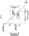
Fig. 5 is a graph showing a relationship between a sub-engine load and generator output characteristics of the present invention. -
Fig. 6 is a diagram showing a relationship between an engine rotation speed or the like and a cooling capacity of the present invention. -
Fig. 7 is a diagram showing a numerical example ofFig. 6 . -
Fig. 8 is a diagram showing a modification example ofFig. 1 . -
Fig. 9 is a diagram showing another modification example ofFig. 1 . - Hereinafter, embodiments according to the present invention will be described with reference to the drawings.
- Hereinafter, a first embodiment of the present invention will be described with reference to
Figs. 1 to 5 . - As shown in
Fig. 1 , arefrigeration unit 1 according to the present embodiment is a so-called flush mount type refrigeration unit mounted on a front end portion of a carrier of a transportation vehicle (vehicle) 2. - As shown in
Fig. 2 , therefrigeration unit 1 includes asub-engine 3, a one-stage transmission 4 which is connected to thesub-engine 3, a three-phase AC generator (generator) 5 which is connected to the one-stage transmission 4, an external power supply input device 6 which can receive power from the outside of thetransportation vehicle 2, and a three-phase induction motor (electric motor) 7 which is driven by three-phase AC power generated by the three-phase AC generator 5 and power from an external power supply. - As shown in
Figs. 3 and 4 , thesub-engine 3 includes anengine output shaft 11 which extends in a direction of the one-stage transmission 4 and transmits a driving force to the three-phase AC generator 5 or the like via theengine output shaft 11. In addition, thesub-engine 3 is covered with an engine room enclosure (not shown). Thesub-engine 3 of the present embodiment does not include a mechanism (solenoid) which adjust an engine rotation speed, and during a normal operation, continuously maintains a constant rotation speed (a rated rotation speed in the present embodiment). The rated rotation speed of thesub-engine 3 is a rotation speed corresponding to the maximum load of the three-phase AC generator 5. - The one-
stage transmission 4 includes agear portion 12 which shifts an input rotation speed, an input shaft (input shaft portion) 13 which extends in a direction of the sub-engine 3 from thegear portion 12, and an output shaft (output shaft portion) 14 which is connected to the three-phase AC generator 5. Thegear portion 12 includes aninput gear 15 which is connected to theinput shaft 13 and anoutput gear 16 which is connected to theoutput shaft 14. Theinput gear 15 and theoutput gear 16 are disposed so as to engage with each other. An engagement aspect between theinput gear 15 and theoutput gear 16 is performed such that theoutput gear 16 is positioned above theinput gear 15. Accordingly, a positional relationship between theoutput shaft 14 and theinput shaft 13 which are respectively connected to theoutput gear 16 and theinput gear 15 is satisfied such that theoutput shaft 14 is positioned above theinput shaft 13. - The
engine output shaft 11 of thesub-engine 3 and theinput shaft 13 of the one-stage transmission 4 are connected to each other via an anti-vibration coupling (anti-vibration portion) 17. Theanti-vibration coupling 17 is hermetically covered with aseal coupling box 18. In addition, the one-stage transmission 4 is hermetically covered with a sealed gearbox (sealed box) 19. Inside of the sealedgearbox 19 is oily by lubricant for a smooth operation of thegear portion 12. - The three-phase AC generator 5 is connected to the one-
stage transmission 4 by theoutput shaft 14 of the one-stage transmission 4, and driven by a predetermined generator input rotation speed (predetermined generator rotation speed) shifted by the one-stage transmission 4, and thus, converts the driving force ofsub-engine 3 into three-phase AC power consisting of a U phase, a V phase, a W phase. In this case, a frequency of the converted three-phase AC power is the same as a frequency of the external power supply described later. The three-phase AC power output from the three-phase AC generator 5 is fed to the three-phase induction motor 7 via anelectric circuit 20. At this case, the power of the U phase, the V phase, and the W phase flows through correspondingelectric circuits - A
battery 21 which is a power supply for starting thesub-engine 3 is disposed below the three-phase AC generator 5. Thesub-engine 3 and thebattery 21 are connected to each other by a battery cable (not shown). When the sub-engine 3 starts, the power is fed from thebattery 21 tosub-engine 3 via the battery cable, and a start operation of thesub-engine 3 is started. - The external power supply input device 6 can input the power from an external power supply (in the present embodiment, a commercial power supply in a use area) of the
transportation vehicle 2 to thetransportation vehicle 2. Accordingly, for example, in a case where the commercial power supply is in an environment where the commercial power supply can be used, by connecting the commercial power supply and the external power supply input device 6 to each other, the power from the commercial power supply is input to thetransportation vehicle 2 via the external power supply input device, and the power from the commercial power supply can be used in therefrigeration unit 1. - The three-phase induction motor 7 can be driven by both the power generated by the three-phase AC generator 5 and the power from the outside of the transportation vehicle inputted via the external power supply input device 6, and by switching between a generator-
side switch 22 and an external power supply-side switch 23 according to a usage situation of the transportation vehicle, the three-phase AC generator 5 and the external power supply can be selectively used. In addition, the power generated by the three-phase AC generator 5 and the power input from external power supply can also be fed to electronic equipment other than the three-phase induction motor 7 configuring therefrigeration unit 1. - Action and effect exerted by the
refrigeration unit 1 of the above-described present embodiment will be described. - In the present embodiment, the engine rotation speed of the
sub-engine 3 can be converted into a predetermined generator input rotation speed by the one-stage transmission 4, and thus, the rotation speed of the three-phase AC generator 5 can be a desired generator input rotation speed without depending on the engine rotation speed of thesub-engine 3. Therefore, the frequency of the power generated by the three-phase AC generator 5 is determined by the generator input rotation speed of the three-phase AC generator 5, and thus, the frequency of the power supply of the three-phase AC generator 5 can be a desired frequency without depending on the engine rotation speed. - Moreover, by the one-
stage transmission 4, the engine rotation speed of thesub-engine 3 is converted into the generator input rotation speed of the three-phase AC generator 5 by which the frequency of the power supply of the three-phase AC generator 5 and the frequency of the external power supply (the commercial power supply of the use area) of thetransportation vehicle 2 are the same as each other. Accordingly, the frequency of the generator power supply is the same as the frequency of the external power supply. Therefore, when power is supplied to the electronic equipment such as the three-phase induction motor 7 included in therefrigeration unit 1, even in a case where the generator power supply is used or in a case where the external power supply is used, the power supply having the same frequency can be used, and thus, it is possible to share design of the electronic equipment such as the three-phase induction motor 7. - Moreover, as the transmission mechanism which converts the engine rotation speed into a predetermined generator input rotation speed, the one-
stage transmission 4 is applied. Therefore, compared to a case where a multistage transmission or a continuously variable transmission is applied, it is possible to reduce a size of the transmission mechanism. Accordingly, the transmission mechanism can be appropriately installed in thetransportation vehicle 2 which is required to secure a passenger compartment space or a transport space. - Moreover, the one-
stage transmission 4 is applied and the size of the transmission mechanism can be reduced, and accordingly, it is possible to reduce a size of an engine room enclosure in which thesub-engine 3, the one-stage transmission 4, and the three-phase AC generator 5 are accommodated. The size of the engine room enclosure is reduced, and thus, it is possible to improve sealability and shielding performance of the engine room enclosure. Accordingly, noise caused by the driving of thesub-engine 3 is hardly radiated to the outside, and the noise can be reduced. - In addition, the one-
stage transmission 4 is applied, and thus, the transmission mechanism can be made simpler than the multistage transmission or the continuously variable transmission, and maintainability can be enhanced. Moreover, in the present embodiment, a mechanism (the solenoid or the like) which adjusts the engine rotation speed is not provided in thesub-engine 3, and thus, it is possible to reduce the size of thesub-engine 3, the number of parts decrease, and it is possible to decrease a cost. - Moreover, in the above-described configuration, the engine rotation speed of the
sub-engine 3 is set to the rated rotation speed corresponding to the maximum generated load. Therefore, it is possible to appropriately maintain the operation at the engine rotation speed which is the maximum generated load of the three-phase AC generator 5 while maintaining the generator rotation speed having a predetermined effect. - In the above-described configuration, as the transmission mechanism, the one-
stage transmission 4 having a relatively small size is applied, and thus, the size of the sealedgearbox 19 which seals the one-stage transmission 4 and the size of theseal coupling box 18 which seals a portion of the one-stage transmission 4 can be reduced, and it is possible to simply the seal the one-stage transmission 4. Accordingly, it is possible to easily suppress the noise of the one-stage transmission 4. In addition, in a case where oil is sealed inside the sealedgearbox 19, it is possible to easily increase lubricity of the one-stage transmission 4. - In the above-described configuration, the
anti-vibration coupling 17 is provided in the connection portion between theengine output shaft 11 and theinput shaft 13, and thus, theanti-vibration coupling 17 absorbs torque fluctuations caused by the drive of thesub-engine 3, and it is possible to suppress vibrations of the one-stage transmission 4 connected to thesub-engine 3. Accordingly, it is possible to decrease the noise caused by the vibrations of the one-stage transmission 4. - In the above-described configuration, the axis of the
output shaft 14 is positioned above the axis of theinput shaft 13, and thus, a space is formed below theoutput shaft 14. In the above-described configuration, thebattery 21 for starting thesub-engine 3 is provided in the space, and thus, a distance between thesub-engine 3 and thebattery 21 can be set to a relatively short distance only via the one-stage transmission 4. Accordingly, it is possible to shorten the battery cable which connects thesub-engine 3 and thebattery 21 to each other, and thus, a starter voltage drop is suppressed, and it is possible to improve startability of thesub-engine 3. In addition, when thesub-engine 3 is started, a large current flows to the battery cable which connects thesub-engine 3 and thebattery 21 to each other. However, the battery cable can be shortened, and thus, it is possible to minimize the voltage drop when the engine is started, and it is possible to improve stability. - Moreover, in the present embodiment, the example is described in which the rated rotation speed (the rotation speed corresponding to the frequency of the commercial power supply of the use area) of the
sub-engine 3 is the rotation speed corresponding to the maximum load of the three-phase AC generator 5. However, the rated rotation speed of thesub-engine 3 may be a rotation speed corresponding to an intermediate load (hereinafter, referred to as an "intermediate load") between the maximum load and the minimum load which is a load lower than an operating point (ATP refrigerating condition operating point) adopted by a general transport refrigerator as shown inFig. 5 . In a case where the rated rotation speed is in the intermediate load, even if there are some variations in the engine rotation speed due to a usage circumstance or the like, a generated power output of the three-phase AC generator 5 can be a voltage and a frequency within a usable range (within a range from -10% to +10% of the voltage of the commercial power supply in the use area and -3% to +3% of the frequency of the commercial power supply of the use area) of general electronic equipment and the three-phase induction motor 7. Therefore, the use range of the present equipment can be included in the usable range of a general electronic equipment or the like. - Next, a second embodiment of the present invention will be described with reference to
Figs. 6 and7 . - Compared to the first embodiment, in the present embodiment, setting of the engine rotation speed of the
sub-engine 3 is partially different. Other matters are similar to those of the first embodiment, and thus, descriptions thereof are omitted. - The engine rotation speed of the
sub-engine 3 of the present embodiment is set to a rotation speed corresponding to a desired cooling capacity of the refrigerator, and a gear reduction ratio of the one-stage transmission 4 is set to a ratio by which the engine rotation speed is shifted to a predetermined generator input rotation speed. - As shown in
Fig. 6 , in a case where it is desired to obtain a large cooling capacity in the refrigerator, the engine rotation speed is high and the gear reduction ratio increases in order to shift the high engine rotation speed to a predetermined generator input rotation speed. Meanwhile, in a case where it is desired to obtain a low cooling capacity in the refrigerator, the engine rotation speed is low and the gear reduction ratio decreases. If a specific numerical example is shown, as shown inFig. 7 , for example, in the case where it is desired to obtain the large cooling capacity, the engine rotation speed is set to 1875 rpm, the gear reduction ratio is set to 1.25/1, and thus, the generator input rotation speed becomes 1500 rpm. In the case where it is desired to obtain the low cooling capacity, the engine rotation speed is set to 1200 rpm, the gear reduction ratio is set to 1/1.25, and thus, the generator input rotation speed becomes 1500 rpm. In this way, the generator input rotation speed of the three-phase AC generator 5 can be made constant without being influenced by the engine rotation speed of thesub-engine 3. - As described above, even if the engine rotation speed is changed according to the cooling capacity, the generator input rotation speed can be set to a constant rotation speed simply by changing the gear reduction ratio, and thus, a desired cooling capacity can be obtained while the predetermined generator rotation speed is maintained. In addition, the generator input rotation speed can be set to a constant rotation speed, and thus, the generator output of the three-phase AC generator 5 can be set to a constant voltage and a constant frequency (in the present embodiment, the voltage and the frequency of the commercial power supply in the use area). Accordingly, the general electronic equipment or the three-phase induction motor 7 manufactured for driving the commercial power supply can be used, and the same electronic equipment and three-phase induction motor 7 can be used for all models. That is, by changing only the gear reduction ratio of the one-
stage transmission 4, it is possible to configure therefrigeration unit 1 of various cooling capacity bands, and it is possible to facilitate arrangement according to merchantability. - In addition, in the present embodiment, the engine rotation speed of the
sub-engine 3 is set according to the cooling capacity. However, the setting of the engine rotation speed is not limited to this. For example, the engine rotation speed may be set according to a cost, and the engine rotation speed may be set according a noise level. - Moreover, in the first and second embodiments, the flush mount type refrigeration unit in which the
refrigeration unit 1 is mounted on a front end portion of the carrier of thetransportation vehicle 2 is described. However, the disposition of therefrigeration unit 1 is not limited to this. For example, as shown inFig. 8 , an under mounttype refrigeration unit 30 in which therefrigeration unit 30 is mounted below the carrier may be adopted, or as shown inFig. 9 , a nose mount type refrigeration unit in which therefrigeration unit 40 is mounted to extend forward from an upper portion of a front surface of the carrier may be adopted. -
- 1:
- refrigeration unit
- 3:
- sub-engine
- 4:
- one-stage transmission
- 5:
- three-phase AC generator (generator)
- 6:
- external power supply input device
- 7:
- three-phase induction motor (electric motor)
- 12:
- gear portion
- 13:
- input shaft (input shaft portion)
- 14:
- output shaft (output shaft portion)
- 15:
- input gear
- 16:
- output gear
- 17:
- anti-vibration coupling (anti-vibration portion)
- 19:
- sealed gearbox (sealed box)
- 21:
- battery
Claims (6)
- A refrigeration unit which is mounted on a vehicle and is capable of using a power supply of a generator which generates electricity by a driving force of a sub-engine and an external power supply of the vehicle, the refrigeration unit comprising:an one-stage transmission which connects the sub-engine and the generator to each other and converts an engine rotation speed of the sub-engine into a predetermined generator rotation speed,wherein the predetermined generator rotation speed is set by the one-stage transmission such that a voltage and a frequency of the power supply of the generator are the same as a voltage and a frequency of the external power supply of the vehicle.
- The refrigeration unit according to claim 1,
wherein the engine rotation speed is set to be a rated rotation speed according to a maximum generated load. - The refrigeration unit according to claim 1,
wherein the engine rotation speed is set to a rotation speed corresponding to a desired cooling capacity of a refrigerator. - The refrigeration unit according to any one of claims 1 to 3, further comprising:
a sealed box which seals the one-stage transmission inside the sealed box. - The refrigeration unit according to any one of claims 1 to 4,
wherein an anti-vibration portion is provided in a connection portion between the sub-engine and the one-stage transmission. - The refrigeration unit according to any one of claims 1 to 5,
wherein the one-stage transmission includes an input shaft portion which is connected to the sub-engine and an output shaft portion which is connected to the generator,
wherein an axis of the output shaft portion is positioned above an axis of the input shaft portion, and
wherein a battery which starts the sub-engine is provided below the output shaft portion.
Applications Claiming Priority (2)
| Application Number | Priority Date | Filing Date | Title |
|---|---|---|---|
| JP2016090856A JP6755702B2 (en) | 2016-04-28 | 2016-04-28 | Refrigerator unit |
| PCT/JP2017/016226 WO2017188187A1 (en) | 2016-04-28 | 2017-04-24 | Refrigerator unit |
Publications (2)
| Publication Number | Publication Date |
|---|---|
| EP3422560A1 true EP3422560A1 (en) | 2019-01-02 |
| EP3422560A4 EP3422560A4 (en) | 2019-04-03 |
Family
ID=60161556
Family Applications (1)
| Application Number | Title | Priority Date | Filing Date |
|---|---|---|---|
| EP17789469.8A Withdrawn EP3422560A4 (en) | 2016-04-28 | 2017-04-24 | REFRIGERATOR UNIT |
Country Status (3)
| Country | Link |
|---|---|
| EP (1) | EP3422560A4 (en) |
| JP (1) | JP6755702B2 (en) |
| WO (1) | WO2017188187A1 (en) |
Family Cites Families (11)
| Publication number | Priority date | Publication date | Assignee | Title |
|---|---|---|---|---|
| GB859932A (en) * | 1957-10-18 | 1961-01-25 | Fichtel & Sachs Ag | Improvements in and relating to electric control systems for mobile refrigerating installations |
| JPS5150248U (en) * | 1974-10-12 | 1976-04-16 | ||
| JPS53152324U (en) * | 1977-05-07 | 1978-11-30 | ||
| JPH08105666A (en) * | 1994-08-08 | 1996-04-23 | Mitsubishi Heavy Ind Ltd | Refrigerator for transportation |
| CA2146394A1 (en) * | 1995-04-05 | 1996-10-06 | Kazutoshi Furukawa | Power supply apparatus installed under a carrier of a vehicle |
| JPH08300937A (en) * | 1995-05-08 | 1996-11-19 | Mitsubishi Heavy Ind Ltd | Refrigerating and air conditioning device for vehicle |
| NL1009520C2 (en) * | 1998-06-30 | 2000-01-04 | Klaas Schimmel | Closed loop air conditioning system installed in land, sea or air vehicle is powered by vehicle's own D.C. electrical supply augmented by solar panels |
| JP2000283623A (en) * | 1999-03-29 | 2000-10-13 | Toshiba Corp | Refrigeration equipment for refrigerator cars |
| JP4426737B2 (en) * | 2000-06-28 | 2010-03-03 | 東芝キヤリア株式会社 | Refrigeration equipment for vehicles |
| KR200338908Y1 (en) * | 2003-10-14 | 2004-01-16 | 주식회사 캄코 | Cooling fan motor assembly for an automobile |
| FR2993505B1 (en) * | 2012-07-19 | 2015-06-26 | Leroy Somer Moteurs | ASSEMBLY COMPRISING A GENERATOR AND ELECTRIC MOTORS FOR AN AIR CONDITIONING OR REFRIGERATION SYSTEM FOR A VEHICLE. |
-
2016
- 2016-04-28 JP JP2016090856A patent/JP6755702B2/en active Active
-
2017
- 2017-04-24 EP EP17789469.8A patent/EP3422560A4/en not_active Withdrawn
- 2017-04-24 WO PCT/JP2017/016226 patent/WO2017188187A1/en not_active Ceased
Also Published As
| Publication number | Publication date |
|---|---|
| JP2017200373A (en) | 2017-11-02 |
| WO2017188187A1 (en) | 2017-11-02 |
| JP6755702B2 (en) | 2020-09-16 |
| EP3422560A4 (en) | 2019-04-03 |
Similar Documents
| Publication | Publication Date | Title |
|---|---|---|
| US10899192B2 (en) | Tractor trailer refrigeration unit | |
| CN101391581B (en) | Powertrain with torque converter-mounted generator for multiple voltage electrical power and method for assembling same | |
| US7250688B2 (en) | Narrow range variable frequency starter/generator system | |
| US7977830B2 (en) | Structure for mounting vehicle driving apparatus | |
| EP2450217A2 (en) | Cooling system | |
| EP0806315A1 (en) | Hybrid power system using an electric coupling for the differential drive of distributed loads | |
| US20170267092A1 (en) | Electric Drive Unit, Hybrid Drive Device, And Vehicle | |
| EP2174078A1 (en) | Transport refrigeration series hybrid power supply | |
| KR101716456B1 (en) | Power feed system for refrigerator truck | |
| EP2372880A2 (en) | Low profile starter-generator | |
| EP1992840A1 (en) | Drive pulleys | |
| US12145424B2 (en) | Vehicle temperature control system | |
| US20190001802A1 (en) | Device for driving vehicle | |
| KR101532834B1 (en) | Second Stage Driving Apparatus For Reducing Speed Of Hybrid And Electricity Car | |
| KR102465093B1 (en) | automotive gearbox | |
| US20230420977A1 (en) | Architecture and control system for electrically-powered accessories of a non-hybrid vehicle | |
| KR20180054781A (en) | Feeding device for feeding oil | |
| JP7187454B2 (en) | Method and apparatus for operating a power pack | |
| US20080087480A1 (en) | Device for Generating Electrical Energy for an Agricultural or Industrial Utility Vehicle | |
| US11180017B2 (en) | Device for driving vehicle | |
| KR101573093B1 (en) | A vehicle drive system and use of an electromechanical converter | |
| JP6755702B2 (en) | Refrigerator unit | |
| JP2011508698A (en) | Auxiliary drive system and use of electromechanical converter | |
| EP3240184B1 (en) | Method for implementing a pmg varaible speed constant frequency generating system and a control processor | |
| US12404836B2 (en) | Wind power generator |
Legal Events
| Date | Code | Title | Description |
|---|---|---|---|
| STAA | Information on the status of an ep patent application or granted ep patent |
Free format text: STATUS: THE INTERNATIONAL PUBLICATION HAS BEEN MADE |
|
| PUAI | Public reference made under article 153(3) epc to a published international application that has entered the european phase |
Free format text: ORIGINAL CODE: 0009012 |
|
| STAA | Information on the status of an ep patent application or granted ep patent |
Free format text: STATUS: REQUEST FOR EXAMINATION WAS MADE |
|
| 17P | Request for examination filed |
Effective date: 20180927 |
|
| AK | Designated contracting states |
Kind code of ref document: A1 Designated state(s): AL AT BE BG CH CY CZ DE DK EE ES FI FR GB GR HR HU IE IS IT LI LT LU LV MC MK MT NL NO PL PT RO RS SE SI SK SM TR |
|
| AX | Request for extension of the european patent |
Extension state: BA ME |
|
| RIC1 | Information provided on ipc code assigned before grant |
Ipc: H02P 9/06 20060101AFI20190221BHEP Ipc: B60P 3/20 20060101ALI20190221BHEP Ipc: H02K 7/116 20060101ALI20190221BHEP Ipc: H02K 7/18 20060101ALI20190221BHEP Ipc: B60H 1/00 20060101ALI20190221BHEP Ipc: B60H 1/32 20060101ALI20190221BHEP Ipc: B60R 16/03 20060101ALI20190221BHEP |
|
| A4 | Supplementary search report drawn up and despatched |
Effective date: 20190228 |
|
| DAV | Request for validation of the european patent (deleted) | ||
| DAX | Request for extension of the european patent (deleted) | ||
| STAA | Information on the status of an ep patent application or granted ep patent |
Free format text: STATUS: EXAMINATION IS IN PROGRESS |
|
| 17Q | First examination report despatched |
Effective date: 20191128 |
|
| STAA | Information on the status of an ep patent application or granted ep patent |
Free format text: STATUS: THE APPLICATION IS DEEMED TO BE WITHDRAWN |
|
| 18D | Application deemed to be withdrawn |
Effective date: 20201006 |