EP3422465A1 - Hybrid circuit, power supply circuit, antenna device, and power supply method - Google Patents
Hybrid circuit, power supply circuit, antenna device, and power supply method Download PDFInfo
- Publication number
- EP3422465A1 EP3422465A1 EP17756406.9A EP17756406A EP3422465A1 EP 3422465 A1 EP3422465 A1 EP 3422465A1 EP 17756406 A EP17756406 A EP 17756406A EP 3422465 A1 EP3422465 A1 EP 3422465A1
- Authority
- EP
- European Patent Office
- Prior art keywords
- power supply
- line
- input
- output
- branch
- Prior art date
- Legal status (The legal status is an assumption and is not a legal conclusion. Google has not performed a legal analysis and makes no representation as to the accuracy of the status listed.)
- Granted
Links
- 238000000034 method Methods 0.000 title claims description 21
- 239000000758 substrate Substances 0.000 claims description 46
- 239000004020 conductor Substances 0.000 description 9
- 230000002093 peripheral effect Effects 0.000 description 8
- 230000005855 radiation Effects 0.000 description 8
- 238000002955 isolation Methods 0.000 description 7
- 238000003786 synthesis reaction Methods 0.000 description 5
- 230000003111 delayed effect Effects 0.000 description 4
- 238000010586 diagram Methods 0.000 description 4
- 238000005388 cross polarization Methods 0.000 description 3
- 230000010363 phase shift Effects 0.000 description 3
- 230000010287 polarization Effects 0.000 description 3
- 230000005540 biological transmission Effects 0.000 description 2
- 238000004891 communication Methods 0.000 description 2
- 230000000694 effects Effects 0.000 description 2
- QNRATNLHPGXHMA-XZHTYLCXSA-N (r)-(6-ethoxyquinolin-4-yl)-[(2s,4s,5r)-5-ethyl-1-azabicyclo[2.2.2]octan-2-yl]methanol;hydrochloride Chemical compound Cl.C([C@H]([C@H](C1)CC)C2)CN1[C@@H]2[C@H](O)C1=CC=NC2=CC=C(OCC)C=C21 QNRATNLHPGXHMA-XZHTYLCXSA-N 0.000 description 1
- 238000006243 chemical reaction Methods 0.000 description 1
- 230000008878 coupling Effects 0.000 description 1
- 238000010168 coupling process Methods 0.000 description 1
- 238000005859 coupling reaction Methods 0.000 description 1
- 230000005684 electric field Effects 0.000 description 1
- 238000012986 modification Methods 0.000 description 1
- 230000004048 modification Effects 0.000 description 1
Images


Classifications
-
- H—ELECTRICITY
- H01—ELECTRIC ELEMENTS
- H01P—WAVEGUIDES; RESONATORS, LINES, OR OTHER DEVICES OF THE WAVEGUIDE TYPE
- H01P5/00—Coupling devices of the waveguide type
- H01P5/12—Coupling devices having more than two ports
- H01P5/16—Conjugate devices, i.e. devices having at least one port decoupled from one other port
- H01P5/19—Conjugate devices, i.e. devices having at least one port decoupled from one other port of the junction type
- H01P5/22—Hybrid ring junctions
- H01P5/227—90° branch line couplers
-
- H—ELECTRICITY
- H01—ELECTRIC ELEMENTS
- H01Q—ANTENNAS, i.e. RADIO AERIALS
- H01Q21/00—Antenna arrays or systems
- H01Q21/24—Combinations of antenna units polarised in different directions for transmitting or receiving circularly and elliptically polarised waves or waves linearly polarised in any direction
-
- H—ELECTRICITY
- H01—ELECTRIC ELEMENTS
- H01Q—ANTENNAS, i.e. RADIO AERIALS
- H01Q9/00—Electrically-short antennas having dimensions not more than twice the operating wavelength and consisting of conductive active radiating elements
- H01Q9/04—Resonant antennas
- H01Q9/0407—Substantially flat resonant element parallel to ground plane, e.g. patch antenna
- H01Q9/0414—Substantially flat resonant element parallel to ground plane, e.g. patch antenna in a stacked or folded configuration
-
- H—ELECTRICITY
- H01—ELECTRIC ELEMENTS
- H01Q—ANTENNAS, i.e. RADIO AERIALS
- H01Q9/00—Electrically-short antennas having dimensions not more than twice the operating wavelength and consisting of conductive active radiating elements
- H01Q9/04—Resonant antennas
- H01Q9/0407—Substantially flat resonant element parallel to ground plane, e.g. patch antenna
- H01Q9/0428—Substantially flat resonant element parallel to ground plane, e.g. patch antenna radiating a circular polarised wave
- H01Q9/0435—Substantially flat resonant element parallel to ground plane, e.g. patch antenna radiating a circular polarised wave using two feed points
Definitions
- the present invention relates to a power supply circuit, and particularly relates to a power supply circuit used in a microstrip antenna (also abbreviated to "MSA”, hereinafter), for supplying electric power to an antenna element, and a hybrid circuit used therein.
- MSA microstrip antenna
- a microstrip array antenna is used as an antenna for a communication satellite, an antenna for a scientific satellite, an antenna for a synthetic aperture radar, or an antenna for data transmission.
- the microstrip array antenna includes a plurality of antenna elements arranged at an appropriate interval, and a power supply circuit for exciting the antenna elements.
- Each antenna element includes a microstrip antenna (MSA) element.
- MSA element includes a radiating element.
- PTL 1 discloses a "circularly polarized microstrip type antenna device" using a ring type hybrid circuit as a power supply circuit.
- PTL 1 discloses an MSA of a two-point power supply method.
- a radiator pattern (radiating element) and a hybrid circuit are opposite to each other in a state of being integrated with respective surfaces of first and second dielectric substrates that sandwich an earth plate therebetween.
- Two power supply points of the radiator pattern and two output terminals of the hybrid circuit are aligned to each other at the same positions and connected to each other by two pins passing through the first and second dielectric substrates and the earth plate.
- the hybrid circuit eventually halves supplied high frequency current, causes the phases to differ from each other by 90 degrees, and outputs the current to two pairs of output terminals thereof. Thereby, a circularly polarized wave is radiated from the radiating element. Thus, each MSA radiates only one polarized wave.
- At least one of an input line and an output line of the ring type hybrid circuit is arranged inside the ring-shaped pattern.
- PTL 2 discloses a "microstrip antenna" that does not use a hybrid circuit as a power supply circuit, but is able to switch a polarized wave to be used among four types of a vertically polarized wave, a horizontally polarized wave, a left hand circularly polarized wave, and a right hand circularly polarized wave.
- the microstrip antenna disclosed in PTL 2 includes a radiation system (radiating element) including a first power supply point and a second power supply point that generate polarized waves orthogonal to each other, and a polarization-switching power-supply system switching polarization of a synthesized radio wave by controlling a phase difference between high-frequency output signals at the two power supply points.
- the radiation system and the polarization-switching power-supply system are formed on a printed substrate including a plurality of layers.
- the polarization-switching power-supply system includes a polarization switching means that performs control by which a phase difference occurring, at the two power supply points, between two divided high-frequency output signals having an equal amplitude and an equal phase is caused to be 0 degree, 90 degrees, 180 degrees, or 270 degrees.
- the microstrip antenna when the phase difference is 0 degree or 180 degrees, a vertically polarized wave or a horizontally polarized wave is generated from the radiation system, and when the phase difference is 90 degrees or 270 degrees, a left hand circularly polarized wave or a right hand circularly polarized wave is generated.
- the polarization switching means includes an equal power distributor that divides an input high-frequency signal into two signals having an equal amplitude and an equal phase, a first variable phase shifter located between a first distribution output terminal of the equal power distributor and the first power supply point, a second variable phase shifter located between a second distribution output terminal of the equal power distributor and the second power supply point, and a phase shifter control circuit that controls switching of phase shift amounts in the first and second variable phase shifters.
- PTL 3 discloses a "circularly polarized wave switching type antenna" improving cross polarization discrimination (XPD).
- the circularly polarized wave switching type antenna disclosed in PTL 3 includes: a radiating element including two power supply points and radiating two linearly polarized waves orthogonal to each other; first and second phase shifters that are connected to the respective power supply points of the radiating element and of which phase shift amounts are 180 degrees; a 90-degree hybrid circuit that divides an input signal into two signals at a phase difference of 90 degrees, that is connected to the first and second phase shifters, and that includes another terminated end; and a control means that performs control in such a way as to switch phase shift amounts of the first and second phase shifters to 0 degree or 180 degrees and cause a right hand or left hand circularly polarized wave to be radiated from the radiating element.
- PTL 4 discloses a small-sized integrated "multi-frequency plane antenna" for transmitting and receiving polarized waves of a plurality of frequency bands including a circularly polarized wave.
- the multi-frequency plane antenna disclosed in PTL 4 includes an antenna element including a dielectric substrate, and includes a wiring substrate on which the antenna element is mounted.
- the antenna element includes a first square radiation electrode and a second loop-shaped radiation electrode that are formed on a front surface of the dielectric substrate, an earth electrode formed on a back surface of the dielectric substrate, and four through holes formed at positions of two power supply points of each of the first radiation electrode and the second radiation electrode.
- the wiring substrate is provided with two concentric 90-degree hybrids of one-wavelength loop-shaped conductor patterns of which thicknesses vary every 1/4 wavelength. In each of the 90-degree hybrids, two ports are formed. Two leading ends of each of the ports are connected to two power supply points of each of the radiation electrodes via the through holes.
- PTL 5 discloses a "high-frequency power distribution-synthesis device" suitable for implementation as a monolithic microwave integrated circuit. According to PTL 5, in order to configure the power distribution-synthesis device, a series distribution of halving an impedance of a line and a parallel distribution of doubling an impedance of the line are alternately and repeatedly connected, and thus, the power distribution-synthesis device is configured without using ⁇ /4 lines at all.
- PTL 5 discloses, as one example embodiment, the power distribution-synthesis device that includes a parallel flat-plate balanced line of a characteristic impedance Z 0 , first and second microstrip lines of a characteristic impedance Z 0 /2, and a parallel-flat-plate-balanced-line series distribution unit and a parallel-flat-plate-balanced-line-to-microstop-line conversion unit that are arranged between the parallel flat-plate balanced line and the first and second microstrip lines.
- the circularly polarized microstrip type antenna device disclosed in PTL 1 is capable of radiating (transmitting and receiving) only one polarized wave.
- the power supply circuit supplies electric power at two points (one point for each of two orthogonal directions). For this reason, there is a problem that a configuration becomes complicated and cross polarization discrimination is not improved.
- the power supply circuit also supplies electric power at two points (one point for each of two orthogonal directions).
- the power supply circuit is constituted of the first phase shifter, the second phase shifter, and the 90-degree hybrid circuit. As a result, there is a problem that a configuration of the power supply circuit becomes complicated.
- the power supply circuit supplies electric power at four points (two points for each of two orthogonal directions). For this reason, a sufficient space cannot be secured, and thus, there is a problem that it is difficult to derive sufficient characteristics. Further, since the power supply circuit is constituted of two 90-degree hybrids, there is also a problem that a configuration becomes complicated. Furthermore, the strip line is forcibly bent to form each 90-degree hybrid. For this reason, there is also a problem that a voltage standing wave ratio (VSWR) is low, and a narrow space between the lines results in unimprovement of mutual coupling degree.
- VSWR voltage standing wave ratio
- PTL 5 merely discloses the high-frequency power distribution-synthesis device suitable for implementation as a monolithic microwave integrated circuit.
- An object of the present invention is to provide a hybrid circuit, a power supply circuit, an antenna device, and a power supply method that solve the above-described problems.
- a hybrid circuit includes: a loop-shaped line that includes four partial lines having mutually equal electrical lengths and characteristic impedances; first and second input lines that branch respectively from first and second branch points adjacent to each other via a first partial line of the loop-shaped line; first and second output lines that branch respectively from third and fourth branch points adjacent to each other via a second partial line opposite to the first partial line of the loop-shaped line; and third and fourth output lines that branch respectively from the first and second branch points, wherein an input impedance of each of the first and second input lines is equal to a quarter of a characteristic impedance of the partial line, and an output impedance of each of the first to fourth output lines is equal to half of the characteristic impedance of the partial line.
- a power supply circuit is a power supply circuit using the above-described hybrid circuit, for supplying electric power to an antenna element, wherein the loop-shaped line and the first and second input lines are formed on a surface of a dielectric substrate, the first to fourth output lines include first to fourth through holes respectively formed in another dielectric substrate different from the dielectric substrate, electric power is supplied, at four points, to the antenna element from leading ends of the first to fourth through holes, and a characteristic impedance of the hybrid circuit is equal to half of an impedance of the antenna element.
- An antenna device is an antenna device using the above-described power supply circuit, wherein the power supply circuit includes first and second input ports respectively connected to the first and second input lines, and the antenna element includes: a lower patch that includes first to fourth power supply points respectively connected to leading ends of the first to fourth through holes; and an upper patch that is electromagnetically connected to the lower patch.
- a power supply method is a method for supplying electric power to the above-described antenna device, the power supply method including: supplying a first input signal to the first input port, and thereby supplying first and second output signals to the third and second power supply points, respectively, via the power supply circuit; and supplying a second input signal to the second input port, and thereby supplying third and third output signals to the fourth and first power supply points, respectively, via the power supply circuit.
- a power supply circuit of a small size can be provided.
- Fig. 1 is a circuit diagram illustrating a 90-degree hybrid circuit 10 used as the related power supply circuit.
- the illustrated 90-degree hybrid circuit 10 is also referred to as a branch line coupler.
- the 90-degree hybrid circuit 10 includes a combination of first and second partial lines 11 and 12 of a characteristic impedance Z 0 and third and fourth partial lines 13 and 14 of a characteristic impedance Z 0 / ⁇ 2.
- An electrical length L of each of the partial lines 11 to 14 is equal to ⁇ /4.
- Input-output impedances of four ports P1 to P4 of the 90-degree hybrid circuit 10 are Z 0 .
- the four ports P1 to P4 are also referred to as first to fourth ports, respectively.
- the first port P1 is also referred to as a first input port
- the second port P2 is also referred to as a second input port
- the third port P3 is also referred to as a first output port
- the fourth port P4 is also referred to as a second output port.
- first to fourth partial lines 11 to 14 constitute a loop-shaped line.
- the first partial line 11 and the second partial line 12 are opposite to each other, and are also referred to as short-circuit arms.
- the third partial line 13 and the fourth partial line 14 are opposite to each other, and are also referred to as series arms.
- first partial line 11 is connected, at a first branch point 21, to one end of the third partial line 13.
- the other end of the first partial line 11 is connected, at a second branch point 22, to one end of the fourth partial line 14. Accordingly, the first partial line 11 is arranged between the first branch point 21 and the second branch point 22.
- One end of the second partial line 12 is connected, at a third branch point 23, to the other end of the third partial line 13.
- the other end of the second partial line 12 is connected, at a fourth branch point 24, to the other end of the fourth partial line 14. Accordingly, the second partial line 12 is arranged between the third branch point 23 and the third branch point 24.
- the 90-degree hybrid circuit 10 includes first to fourth branch lines 31 to 34 branching outward from the loop-shaped line (11 to 14), at the first to fourth branch points 21 to 24, respectively.
- the first port (first input port) P1 is connected to the first branch point 21 via the first branch line 31.
- the second port (second input port) P2 is connected to the second branch point 22 via the second branch line 32.
- the first branch line 31 is also referred to as a first input line, and the second branch line 32 is also referred to as a second input line.
- the third port (first output port) P3 is connected to the third branch point 23 via the third branch line 33.
- the fourth port (second output port) P4 is connected to the fourth branch point 34 via the fourth branch line 34.
- the third branch line 33 is also referred to as a first output line
- the fourth branch line 34 is also referred to as a second output line.
- FIG. 1 (A) illustrates the case where an input signal is input from the first input port P1, and (B) illustrates the case where an input signal is input from the second input port P2.
- An input signal supplied from the first input port P1 branches to the first output port P3 and the second output port P4, and is output as a first output signal and a second output signal, respectively.
- Output electric power of each of the first and second output signals is half of the input electric power of the input signal. Phases of the first and second output signals are delayed by 90 degrees at the first output port P3 and delayed by 180 degrees at the second output port P4, from that of the input signal. No signal is output to the second input port P2, and isolation from a peripheral circuit is maintained. In other words, the second input port P2 is disconnected from the peripheral circuit.
- An input signal supplied from the second input port P2 branches to the first output port P3 and the second output port P4, and is output as a first output signal and a second output signal, respectively.
- Output electric power of each of the first and second output signals is half of the input electric power of the input signal.
- the first output signal is output with a phase delayed by 180 degrees from that of the input signal.
- the second output signal is output with a phase delayed by 90 degrees from that of the input signal. No signal is output to the first input port P1, and isolation from the peripheral circuit is maintained. In other words, the first input port P1 is disconnected from the peripheral circuit.
- the 90-degree hybrid circuit 10 causes the input signal to branch to the two output ports P3 and P4. Phases of the two output signals are shifted from each other by 90 degrees.
- a microstrip antenna (MSA) using such a 90-degree hybrid circuit 10 as a power supply circuit is an MSA of a two-point power supply method.
- MSA is capable of radiating (transmitting and receiving) only one polarized wave (in the present example, a circularly polarized wave).
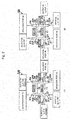
- Fig. 2 is a circuit diagram illustrating a hybrid circuit 10A used as a power supply circuit according to one example embodiment of the present invention.
- the illustrated hybrid circuit 10A is configured and operates similarly to the related 90-degree hybrid circuit 10 illustrated in Fig. 1 , except that a configuration of a loop-shaped line is different and two output lines and two output ports are additionally provided as described later. For this reason, hereinafter, the same reference symbols are given to elements having the functions similar to those of the elements illustrated in Fig. 1 , and the differences are described in detail.
- the illustrated hybrid circuit 10A includes, as a loop-shaped circuit, a first partial line 11, a second partial line 12, a third partial line 13A, and a fourth partial line 14A.
- the third partial line 13A differs from the third partial line 13, and has a characteristic impedance Z 0 .
- the fourth partial line 14A also differs from the fourth partial line 14, and has a characteristic impedance Z 0 .
- Input impedances of first and second ports (first and second input ports) P1 and P2 are equal to Z 0 /4.
- the first port (first input port) P1 is connected to a first branch point 21 via a first branch line (first input line) 31A.
- the second port (second input port) P2 is connected to a second branch point 22 via a second branch line (second input line) 32A.
- Output impedances of third and fourth ports (first and second output ports) P3 and P4 are equal to Z 0 /2.
- the third port (first output port) P3 is connected to a third branch point 23 via a third branch line (first output line) 33A.
- the fourth port (second output port) P4 is connected to a fourth branch point 24 via a fourth branch line (second output line) 34A.
- the illustrated hybrid circuit 10A further includes fifth and sixth ports P5 and P6.
- the fifth port P5 is also referred to as a third output port
- the sixth port P6 is also referred to as a fourth output port.
- Output impedance of each of the fifth and sixth ports (third and fourth output ports) P5 and P6 is equal to Z 0 /2.
- the fifth port (third output port) P5 is connected to the first branch point 21 via a fifth branch line 35.
- the sixth port (fourth output port) P6 is connected to the second branch point 22 via a sixth branch line 36.
- the fifth branch line 35 is also referred to as a third output line
- the sixth branch line 36 is also referred to as a fourth output line.
- FIG. 2 (A) illustrates the case where a first input signal is input from the first input port P1, and (B) illustrates the case where a second input signal is input from the second input port P2.
- the first input signal supplied from the first input port P1 is supplied to the first branch point 21 via the first branch line (first input line) 31A.
- a part of the first input signal at the first branch point 21 is output as a first output signal from the third output port P5 via the fifth branch line (third output line) 35.
- the remaining part of the first input signal at the first branch point 21 passes without change because of being a clockwise signal and a counterclockwise signal the phases of which become opposite to each other at the second branch point 22 and at the third branch point 23, and is output as a second output signal from the second output port P4 by passing through the fourth branch line (second output line) 34A at the fourth branch point 24. Phases of the first output signal and the second output signal are shifted from each other by 180 degrees.
- the second input signal supplied from the second input port P2 is supplied to the second branch point 22 via the second branch line (second input line) 32A.
- a part of the second input signal at the second branch point 22 is output as a third output signal from the fourth output port P6 via the sixth branch line (fourth output line) 36.
- the remaining part of the second input signal at the second branch point 22 passes without change because of being a clockwise signal and a counterclockwise signal the phases of which become opposite to each other at the first branch point 21 and at the fourth branch point 24, and is output as a fourth output signal from the first output port P3 via the third branch line (first output line) 33A at the third branch point 23.
- Phases of the third output signal and the fourth output signal are shifted from each other by 180 degrees. No signal is output to the first input port P1, the third output port P5, and the second output port P4, and isolation from the peripheral circuit is maintained. In other words, the first input port P1, the third output port P5, and the second output port P4 are disconnected from the peripheral circuit.
- the hybrid circuit 10A causes the input signals to branch to the four output ports P3 to P6. Accordingly, by connecting the four output ports P3 to P6 of the hybrid circuit 10A (e.g., via through holes) to four power supply points of an un-illustrated antenna element (radiating element), two linearly polarized waves orthogonal to each other is able to be radiated from the antenna element (radiating element) at the same time.
- a microstrip antenna (MSA) using such a hybrid circuit 10A as a power supply circuit is an MSA of a four-point power supply method.
- Such an MSA is capable of radiating (transmitting and receiving) two polarized waves (in the present example, linearly polarized waves).
- output signals are output only from the output ports (P3, P4) connected to the branch points (23, 24) distant from the branch points (21, 22) to which input signals are supplied.
- output signals are output both from the output ports (P5, P6) connected to the branch points (21, 22) to which input signals are supplied and from the output ports (P3, P4) connected to the branch points (23, 24) distant from the branch ports (21, 22).
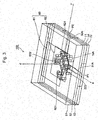
- microstrip antenna (MSA) 100 of a four-point power supply method using as a power supply circuit the hybrid circuit 10A illustrated in Fig. 2 is described with reference to Figs. 3 to 5 .
- Fig. 3 is a transparent perspective view illustrating the MSA 100 of the four-point power supply method.
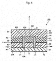
- Fig. 4 is a sectional view of Fig. 3 taken along the Z-X plane.
- Fig. 5 is a sectional view of Fig. 3 taken along the Z-Y plane.
- an orthogonal coordinate system (X,Y,Z) is used.
- the X-axis direction is the front-back direction (depth direction)
- the Y-axis direction is the left-right direction
- the Z-axis direction is the vertical direction (height direction).
- a center of an upper ground conductor 71 described later is set as the origin O of the orthogonal coordinate system (X,Y,Z).
- the illustrated MSA 100 of the four-point power supply method is substantially in the shape of a rectangular parallelepiped.
- the MSA 100 of the four-point power supply method includes first to fourth dielectric substrates 51, 52, 53, and 54. As illustrated in Fig. 3 , the first to fourth dielectric substrates 51 to 54 are stacked from the upper side to the lower side in this order.
- a rectangular upper patch 61 is formed on an upper surface of the first dielectric substrate 51.
- a substantially rectangular lower patch 62 is formed on a lower surface of the first dielectric substrate 51.
- the first dielectric substrate 51 is sandwiched between the upper patch 61 and the lower patch 62.
- the upper patch 61 and the lower patch 62 are electromagnetically coupled. Accordingly, a combination of the upper patch 61 and the lower patch 62 constitutes an MSA element (antenna element) 60.
- the lower patch 62 is sandwiched between the lower surface of the first dielectric substrate 51 and an upper surface of the second dielectric substrate 52.
- the MSA 100 of the four-point power supply method includes the rectangular upper ground conductor 71 and a rectangular lower ground conductor 72.
- the upper ground conductor 71 is sandwiched between a lower surface of the second dielectric substrate 52 and an upper surface of the third dielectric substrate 53.
- the lower ground conductor 72 is formed on a lower surface of the fourth dielectric substrate 54.
- the power supply circuit (hybrid circuit) 10A is formed in such a way as to be substantially sandwiched between a lower surface of the third dielectric substrate 53 and an upper surface of the fourth dielectric substrate 54.
- the first port (first input port) P1 is formed at a front end between the third dielectric substrate 53 and the fourth dielectric substrate 54.
- the second port (second input port) P2 is formed at a right end between the third dielectric substrate 53 and the fourth dielectric substrate 54.
- the first branch line (first input line) 31A extends in the front-back direction X from the first port (first input port) P1.
- the second branch line (second input line) 32A extends in the left-right direction Y from the second port (second input port) P2.
- the loop-shaped lines (11, 12, 13A, 14A) in the power supply circuit (hybrid circuit) 10A is formed, on the upper surface of the fourth dielectric substrate 54, in the shape of a loop around the vertical line Z passing through the origin O.
- the illustrated loop-shaped line (11, 12, 13A, 14A) has a rhombic shape.
- the first branch point 21 is formed on the front side, in the front-back direction X, of the vertical line Z passing through the origin O.
- the second branch point 22 is formed on the right side, in the left-right direction Y, of the vertical line Z passing through the origin O.
- the third branch point 23 is formed on the left side, in the left-right direction Y, of the vertical line Z passing through the origin O.
- the fourth branch point 24 is formed on the back side, in the front-back direction X, of the vertical line Z passing through the origin O.
- the third branch line (first output line) 33A is constituted of a first through hole that is formed in such a way as to extend from the third branch point 23 upward in the vertical direction Z and penetrate through the third dielectric substrate 53 and the second dielectric substrate 52.
- An upper end of the first through hole 33A forms the third port (first output port) P3.
- the third port (first output port) P3 is connected to a first power supply point 621 of the lower patch 62.
- the fourth branch line (second output line) 34A is constituted of a second through hole that is formed in such a way as to extend from the fourth branch point 24 upward in the vertical direction Z and penetrate through the third dielectric substrate 53 and the second dielectric substrate 52.
- An upper end of the second through hole 34A forms the fourth port (second output port) P4.
- the fourth port (second output port) P4 is connected to a second power supply point 622 of the lower patch 62.
- the fifth branch line (third output line) 35 is constituted of a third through hole that is formed in such a way as to extend from the first branch point 21 upward in the vertical direction Z and penetrate through the third dielectric substrate 53 and the second dielectric substrate 52.
- An upper end of the third through hole 35 forms the fifth port (third output port) P5.
- the fifth port (third output port) P5 is connected to a third power supply point 623 of the lower patch 62.
- the sixth branch line (fourth output line) 36 is constituted of a fourth through hole that is formed in such a way as to extend from the second branch point 22 upward in the vertical direction Z and penetrate through the third dielectric substrate 53 and the second dielectric substrate 52.
- An upper end of the fourth through hole 36 forms the sixth port (fourth output port) P6.
- the sixth port (fourth output port) P6 is connected to a fourth power supply point 624 of the lower patch 62.
- the first to fourth output lines 33A, 34A, 35, and 36 are constituted respectively of the first to fourth through holes that are formed in such a way as to penetrate through the third dielectric substrate 53 and the second dielectric substrate 52.
- the upper ground conductor 71 includes first to fourth openings 711, 712, 713, and 714 that are substantially concentric with the first to fourth through holes 33A, 34A, 35, and 36 and have diameters larger than diameters of the first to fourth through holes 33A, 34A, 35, and 36, respectively.
- the lower patch 62 includes first to fourth slits 626, 627, 628, and 629 provided around the first to fourth power supply points 621 to 624, respectively.
- the first to fourth slits 626 to 629 each have a shape of a semi-loop formed at a more inside toward the vertical line Z passing through the origin O than the first to fourth power supply points 621 to 624.
- a characteristic impedance of the power supply circuit (hybrid circuit) 10A is half of an impedance of the MSA element 60.
- the first input signal supplied to the first input port P1 reaches the first branch point 21 by passing through the first input line 31A.
- a part of the first input signal at the first branch point 21 is supplied as a first output signal to the third power supply point 623 of the lower patch 62 from the third output port P5 by passing through the third through hole 35.
- the remaining part of the first input signal that has reached the first branch point 21 passes through the third branch point 23 and the second branch point 22 of the power supply circuit 10A without change for the above-described reason, and is supplied as a second output signal to the second power supply point 622 of the lower patch 62 from the second output port P4 by passing through the second through hole 34A at the fourth branch point 24.
- Phases of the first output signal and the second output signal are shifted from each other by 180 degrees.
- the second input port P2, the fourth output port P6, and the first output port P3 are isolation ports.
- the second input signal supplied to the second input port P2 reaches the second branch point 22 by passing through the second input line 32A.
- a part of the second input signal at the second branch point 22 is supplied as a third output signal to the fourth power supply point 624 of the lower patch 62 from the fourth output port P6 by passing through the fourth through hole 36.
- the remaining part of the second input signal that has reached the second branch point 22 passes through the first branch point 21 and the fourth branch point 24 of the power supply circuit 10A without change for the above-described reason, and is supplied as a fourth output signal to the first power supply point 621 of the lower patch 62 from the first output port P3 by passing through the first through hole 33A at the third branch point 23.
- Phases of the third output signal and the fourth output signal are shifted from each other by 180 degrees.
- the first input port P1, the third output port P5, and the second output port P4 are isolation ports.
- independent electric fields orthogonal to each other can be generated between the third power supply point 623 and the second power supply point 622 of the lower patch 62 and between the fourth power supply point 624 and the first power supply point 621 of the lower patch 62.
- the hybrid circuit 10A is adopted as the power supply circuit of the MSA 100, isolation is improved, and even when electric power is supplied to four points (two points for each of two orthogonal directions), a sufficient space can be secured. For this reason, it is possible to derive sufficient characteristics as the MSA 100.
- the upper patch 61 and the lower patch 62 are electromagnetically connected, it is possible to contribute to widening a band.
- the power supply circuit 10A is arranged in such a way as to be directly connected to the back surface of the MSA element (antenna element) 60, it is possible to provide the small-sized MSA 100 of the four-point power supply method.
- the loop-shaped line is in the shape of a rhombus in the above-described example embodiment (example), but is not limited to this, and may be in the form of a circle (circular ring), and may be in any shape as long as the four partial lines have mutually equal electrical lengths and characteristic impedances.
- the power supply circuit (hybrid circuit) according to the present invention can be used as a power supply circuit for a microstrip array antenna such as an antenna for a communication satellite, an antenna for a scientific satellite, an antenna for a synthetic aperture radar, or an antenna for data transmission.
- a microstrip array antenna such as an antenna for a communication satellite, an antenna for a scientific satellite, an antenna for a synthetic aperture radar, or an antenna for data transmission.
Landscapes
- Variable-Direction Aerials And Aerial Arrays (AREA)
- Waveguide Aerials (AREA)
Abstract
Description
- The present invention relates to a power supply circuit, and particularly relates to a power supply circuit used in a microstrip antenna (also abbreviated to "MSA", hereinafter), for supplying electric power to an antenna element, and a hybrid circuit used therein.
- A microstrip array antenna is used as an antenna for a communication satellite, an antenna for a scientific satellite, an antenna for a synthetic aperture radar, or an antenna for data transmission. The microstrip array antenna includes a plurality of antenna elements arranged at an appropriate interval, and a power supply circuit for exciting the antenna elements. Each antenna element includes a microstrip antenna (MSA) element. Each MSA element includes a radiating element.
- There are various known MSAs using a hybrid circuit as a power supply circuit for supplying electric power to antenna elements (radiating elements).
- For example,
PTL 1 discloses a "circularly polarized microstrip type antenna device" using a ring type hybrid circuit as a power supply circuit.PTL 1 discloses an MSA of a two-point power supply method. In the MSA, a radiator pattern (radiating element) and a hybrid circuit are opposite to each other in a state of being integrated with respective surfaces of first and second dielectric substrates that sandwich an earth plate therebetween. Two power supply points of the radiator pattern and two output terminals of the hybrid circuit are aligned to each other at the same positions and connected to each other by two pins passing through the first and second dielectric substrates and the earth plate. The hybrid circuit eventually halves supplied high frequency current, causes the phases to differ from each other by 90 degrees, and outputs the current to two pairs of output terminals thereof. Thereby, a circularly polarized wave is radiated from the radiating element. Thus, each MSA radiates only one polarized wave. - According to this circularly polarized microstrip type antenna device disclosed in
PTL 1, at least one of an input line and an output line of the ring type hybrid circuit is arranged inside the ring-shaped pattern. - As described above, it is sufficient that an MSA so far uses only one polarized wave. However, the number of channels has increased recently, thus increasing demands for a "dual-polarization antenna" that simultaneously uses two polarized waves at a time for effectively using frequencies.
- Therefore, various dual-polarization antennas that include an MSA capable of radiating (transmitting and receiving) a plurality of polarized waves have been proposed as well.
- For example,
PTL 2 discloses a "microstrip antenna" that does not use a hybrid circuit as a power supply circuit, but is able to switch a polarized wave to be used among four types of a vertically polarized wave, a horizontally polarized wave, a left hand circularly polarized wave, and a right hand circularly polarized wave. The microstrip antenna disclosed inPTL 2 includes a radiation system (radiating element) including a first power supply point and a second power supply point that generate polarized waves orthogonal to each other, and a polarization-switching power-supply system switching polarization of a synthesized radio wave by controlling a phase difference between high-frequency output signals at the two power supply points. The radiation system and the polarization-switching power-supply system are formed on a printed substrate including a plurality of layers. The polarization-switching power-supply system includes a polarization switching means that performs control by which a phase difference occurring, at the two power supply points, between two divided high-frequency output signals having an equal amplitude and an equal phase is caused to be 0 degree, 90 degrees, 180 degrees, or 270 degrees. According to the microstrip antenna with such a configuration, when the phase difference is 0 degree or 180 degrees, a vertically polarized wave or a horizontally polarized wave is generated from the radiation system, and when the phase difference is 90 degrees or 270 degrees, a left hand circularly polarized wave or a right hand circularly polarized wave is generated. Specifically, the polarization switching means includes an equal power distributor that divides an input high-frequency signal into two signals having an equal amplitude and an equal phase, a first variable phase shifter located between a first distribution output terminal of the equal power distributor and the first power supply point, a second variable phase shifter located between a second distribution output terminal of the equal power distributor and the second power supply point, and a phase shifter control circuit that controls switching of phase shift amounts in the first and second variable phase shifters. - Further,
PTL 3 discloses a "circularly polarized wave switching type antenna" improving cross polarization discrimination (XPD). The circularly polarized wave switching type antenna disclosed inPTL 3 includes: a radiating element including two power supply points and radiating two linearly polarized waves orthogonal to each other; first and second phase shifters that are connected to the respective power supply points of the radiating element and of which phase shift amounts are 180 degrees; a 90-degree hybrid circuit that divides an input signal into two signals at a phase difference of 90 degrees, that is connected to the first and second phase shifters, and that includes another terminated end; and a control means that performs control in such a way as to switch phase shift amounts of the first and second phase shifters to 0 degree or 180 degrees and cause a right hand or left hand circularly polarized wave to be radiated from the radiating element. - Furthermore,
PTL 4 discloses a small-sized integrated "multi-frequency plane antenna" for transmitting and receiving polarized waves of a plurality of frequency bands including a circularly polarized wave. The multi-frequency plane antenna disclosed inPTL 4 includes an antenna element including a dielectric substrate, and includes a wiring substrate on which the antenna element is mounted. The antenna element includes a first square radiation electrode and a second loop-shaped radiation electrode that are formed on a front surface of the dielectric substrate, an earth electrode formed on a back surface of the dielectric substrate, and four through holes formed at positions of two power supply points of each of the first radiation electrode and the second radiation electrode. The wiring substrate is provided with two concentric 90-degree hybrids of one-wavelength loop-shaped conductor patterns of which thicknesses vary every 1/4 wavelength. In each of the 90-degree hybrids, two ports are formed. Two leading ends of each of the ports are connected to two power supply points of each of the radiation electrodes via the through holes. - Although not directly related to a "power supply circuit" according to the present invention,
PTL 5 discloses a "high-frequency power distribution-synthesis device" suitable for implementation as a monolithic microwave integrated circuit. According toPTL 5, in order to configure the power distribution-synthesis device, a series distribution of halving an impedance of a line and a parallel distribution of doubling an impedance of the line are alternately and repeatedly connected, and thus, the power distribution-synthesis device is configured without using λ/4 lines at all. For example,PTL 5 discloses, as one example embodiment, the power distribution-synthesis device that includes a parallel flat-plate balanced line of a characteristic impedance Z0, first and second microstrip lines of a characteristic impedance Z0/2, and a parallel-flat-plate-balanced-line series distribution unit and a parallel-flat-plate-balanced-line-to-microstop-line conversion unit that are arranged between the parallel flat-plate balanced line and the first and second microstrip lines. -
- [PTL 1] Japanese Patent No.
2709383 - [PTL 2] Japanese Unexamined Patent Application Publication No.
H9-284031 - [PTL 3] Japanese Unexamined Patent Application Publication No.
2000-223942 - [PTL 4] Japanese Unexamined Patent Application Publication No.
2003-152431 - [PTL 5] Japanese Unexamined Patent Application Publication No.
H9-246817 - Even when scanning a microstrip array antenna in which a plurality of such MSA elements are arranged, a still wider scanning range has been demanded. This has increased necessity of narrowing an interval between the antenna elements (MSA elements). As a result, it has become necessary to miniaturize a power supply circuit for supplying electric power to the MSA elements.
- However, the following problems exist in the above-described
PTLs 1 to 4, respectively. - The circularly polarized microstrip type antenna device disclosed in
PTL 1 is capable of radiating (transmitting and receiving) only one polarized wave. - According to the microstrip antenna (MSA) disclosed in
PTL 2, the power supply circuit supplies electric power at two points (one point for each of two orthogonal directions). For this reason, there is a problem that a configuration becomes complicated and cross polarization discrimination is not improved. - Further, according to the circularly polarized wave switching type antenna disclosed in
PTL 3, the power supply circuit also supplies electric power at two points (one point for each of two orthogonal directions). According toPTL 3, in order to improve cross polarization discrimination, the power supply circuit is constituted of the first phase shifter, the second phase shifter, and the 90-degree hybrid circuit. As a result, there is a problem that a configuration of the power supply circuit becomes complicated. - According to the multi-frequency plane antenna disclosed in
PTL 4, the power supply circuit supplies electric power at four points (two points for each of two orthogonal directions). For this reason, a sufficient space cannot be secured, and thus, there is a problem that it is difficult to derive sufficient characteristics. Further, since the power supply circuit is constituted of two 90-degree hybrids, there is also a problem that a configuration becomes complicated. Furthermore, the strip line is forcibly bent to form each 90-degree hybrid. For this reason, there is also a problem that a voltage standing wave ratio (VSWR) is low, and a narrow space between the lines results in unimprovement of mutual coupling degree. - Note that
PTL 5 merely discloses the high-frequency power distribution-synthesis device suitable for implementation as a monolithic microwave integrated circuit. - An object of the present invention is to provide a hybrid circuit, a power supply circuit, an antenna device, and a power supply method that solve the above-described problems.
- A hybrid circuit according to the present invention includes: a loop-shaped line that includes four partial lines having mutually equal electrical lengths and characteristic impedances; first and second input lines that branch respectively from first and second branch points adjacent to each other via a first partial line of the loop-shaped line; first and second output lines that branch respectively from third and fourth branch points adjacent to each other via a second partial line opposite to the first partial line of the loop-shaped line; and third and fourth output lines that branch respectively from the first and second branch points, wherein an input impedance of each of the first and second input lines is equal to a quarter of a characteristic impedance of the partial line, and an output impedance of each of the first to fourth output lines is equal to half of the characteristic impedance of the partial line.
- A power supply circuit according to the present invention is a power supply circuit using the above-described hybrid circuit, for supplying electric power to an antenna element, wherein the loop-shaped line and the first and second input lines are formed on a surface of a dielectric substrate, the first to fourth output lines include first to fourth through holes respectively formed in another dielectric substrate different from the dielectric substrate, electric power is supplied, at four points, to the antenna element from leading ends of the first to fourth through holes, and a characteristic impedance of the hybrid circuit is equal to half of an impedance of the antenna element.
- An antenna device according to the present invention is an antenna device using the above-described power supply circuit, wherein the power supply circuit includes first and second input ports respectively connected to the first and second input lines, and the antenna element includes: a lower patch that includes first to fourth power supply points respectively connected to leading ends of the first to fourth through holes; and an upper patch that is electromagnetically connected to the lower patch.
- A power supply method according to the present invention is a method for supplying electric power to the above-described antenna device, the power supply method including: supplying a first input signal to the first input port, and thereby supplying first and second output signals to the third and second power supply points, respectively, via the power supply circuit; and supplying a second input signal to the second input port, and thereby supplying third and third output signals to the fourth and first power supply points, respectively, via the power supply circuit.
- According to the present invention, a power supply circuit of a small size can be provided.
-
- [
Fig. 1] Fig. 1 is a circuit diagram illustrating a 90-degree hybrid circuit used as a related power supply circuit, (A) illustrates the case where an input signal is input from a first input port P1, and (B) illustrates the case where an input signal is input from a second input port P2. - [
Fig. 2] Fig. 2 is a circuit diagram illustrating a hybrid circuit used as a power supply circuit according to one example embodiment of the present invention, (A) illustrates the case where a first input signal is input from a first input port P1, and (B) illustrates the case where a second input signal is input from a second input port P2. - [
Fig. 3] Fig. 3 is a transparent perspective view illustrating a microstrip antenna (MSA) of the four-point power supply method, using as a power supply circuit the hybrid circuit illustrated inFig. 2 . - [
Fig. 4] Fig. 4 is a sectional view ofFig. 3 taken along the Z-X plane. - [
Fig. 5] Fig. 5 is a sectional view ofFig. 3 taken along the Z-Y plane. - In order to facilitate understanding of the present invention, a related power supply circuit used in
PTL 1 and the like is described. -
Fig. 1 is a circuit diagram illustrating a 90-degree hybrid circuit 10 used as the related power supply circuit. The illustrated 90-degree hybrid circuit 10 is also referred to as a branch line coupler. - The 90-
degree hybrid circuit 10 includes a combination of first and secondpartial lines partial lines partial lines 11 to 14 is equal to λ/4. Input-output impedances of four ports P1 to P4 of the 90-degree hybrid circuit 10 are Z0. The four ports P1 to P4 are also referred to as first to fourth ports, respectively. - Here, the first port P1 is also referred to as a first input port, the second port P2 is also referred to as a second input port, the third port P3 is also referred to as a first output port, and the fourth port P4 is also referred to as a second output port.
- Specifically, the first to fourth
partial lines 11 to 14 constitute a loop-shaped line. The firstpartial line 11 and the secondpartial line 12 are opposite to each other, and are also referred to as short-circuit arms. The thirdpartial line 13 and the fourthpartial line 14 are opposite to each other, and are also referred to as series arms. - One end of the first
partial line 11 is connected, at afirst branch point 21, to one end of the thirdpartial line 13. The other end of the firstpartial line 11 is connected, at asecond branch point 22, to one end of the fourthpartial line 14. Accordingly, the firstpartial line 11 is arranged between thefirst branch point 21 and thesecond branch point 22. One end of the secondpartial line 12 is connected, at athird branch point 23, to the other end of the thirdpartial line 13. The other end of the secondpartial line 12 is connected, at afourth branch point 24, to the other end of the fourthpartial line 14. Accordingly, the secondpartial line 12 is arranged between thethird branch point 23 and thethird branch point 24. - The 90-
degree hybrid circuit 10 includes first tofourth branch lines 31 to 34 branching outward from the loop-shaped line (11 to 14), at the first to fourth branch points 21 to 24, respectively. - The first port (first input port) P1 is connected to the
first branch point 21 via thefirst branch line 31. The second port (second input port) P2 is connected to thesecond branch point 22 via thesecond branch line 32. Thefirst branch line 31 is also referred to as a first input line, and thesecond branch line 32 is also referred to as a second input line. The third port (first output port) P3 is connected to thethird branch point 23 via thethird branch line 33. The fourth port (second output port) P4 is connected to thefourth branch point 34 via thefourth branch line 34. Thethird branch line 33 is also referred to as a first output line, and thefourth branch line 34 is also referred to as a second output line. - In
Fig. 1 , (A) illustrates the case where an input signal is input from the first input port P1, and (B) illustrates the case where an input signal is input from the second input port P2. - First, an operation when an input signal is input from the first input port P1 is described with reference to
Fig. 1(A) . - An input signal supplied from the first input port P1 branches to the first output port P3 and the second output port P4, and is output as a first output signal and a second output signal, respectively. Output electric power of each of the first and second output signals is half of the input electric power of the input signal. Phases of the first and second output signals are delayed by 90 degrees at the first output port P3 and delayed by 180 degrees at the second output port P4, from that of the input signal. No signal is output to the second input port P2, and isolation from a peripheral circuit is maintained. In other words, the second input port P2 is disconnected from the peripheral circuit.
- Next, an operation when an input signal is input from the second input port P2 is described with reference to
Fig. 1(B) . - An input signal supplied from the second input port P2 branches to the first output port P3 and the second output port P4, and is output as a first output signal and a second output signal, respectively. Output electric power of each of the first and second output signals is half of the input electric power of the input signal. To the first output port P3, the first output signal is output with a phase delayed by 180 degrees from that of the input signal. To the second output port P4, the second output signal is output with a phase delayed by 90 degrees from that of the input signal. No signal is output to the first input port P1, and isolation from the peripheral circuit is maintained. In other words, the first input port P1 is disconnected from the peripheral circuit.
- In this manner, the 90-
degree hybrid circuit 10 causes the input signal to branch to the two output ports P3 and P4. Phases of the two output signals are shifted from each other by 90 degrees. - Accordingly, by connecting the two output ports P3 and P4 of the 90-degree hybrid circuit 10 (e.g., via through holes) to two power supply points of an un-illustrated antenna element (radiating element), a circularly polarized wave is able to be radiated from the antenna element (radiating element).
- Thus, it can be understood that a microstrip antenna (MSA) using such a 90-
degree hybrid circuit 10 as a power supply circuit is an MSA of a two-point power supply method. However, such an MSA is capable of radiating (transmitting and receiving) only one polarized wave (in the present example, a circularly polarized wave). - Next, an example embodiment for implementing the invention is described in detail with reference to the drawings.
-
Fig. 2 is a circuit diagram illustrating ahybrid circuit 10A used as a power supply circuit according to one example embodiment of the present invention. - The illustrated
hybrid circuit 10A is configured and operates similarly to the related 90-degree hybrid circuit 10 illustrated inFig. 1 , except that a configuration of a loop-shaped line is different and two output lines and two output ports are additionally provided as described later. For this reason, hereinafter, the same reference symbols are given to elements having the functions similar to those of the elements illustrated inFig. 1 , and the differences are described in detail. - The illustrated
hybrid circuit 10A includes, as a loop-shaped circuit, a firstpartial line 11, a secondpartial line 12, a thirdpartial line 13A, and a fourthpartial line 14A. - The third
partial line 13A differs from the thirdpartial line 13, and has a characteristic impedance Z0. The fourthpartial line 14A also differs from the fourthpartial line 14, and has a characteristic impedance Z0. - Accordingly, each of the first to fourth
partial lines - Input impedances of first and second ports (first and second input ports) P1 and P2 are equal to Z0/4. The first port (first input port) P1 is connected to a
first branch point 21 via a first branch line (first input line) 31A. The second port (second input port) P2 is connected to asecond branch point 22 via a second branch line (second input line) 32A. - Output impedances of third and fourth ports (first and second output ports) P3 and P4 are equal to Z0/2. The third port (first output port) P3 is connected to a
third branch point 23 via a third branch line (first output line) 33A. The fourth port (second output port) P4 is connected to afourth branch point 24 via a fourth branch line (second output line) 34A. - The illustrated
hybrid circuit 10A further includes fifth and sixth ports P5 and P6. The fifth port P5 is also referred to as a third output port, and the sixth port P6 is also referred to as a fourth output port. Output impedance of each of the fifth and sixth ports (third and fourth output ports) P5 and P6 is equal to Z0/2. The fifth port (third output port) P5 is connected to thefirst branch point 21 via afifth branch line 35. The sixth port (fourth output port) P6 is connected to thesecond branch point 22 via asixth branch line 36. Thefifth branch line 35 is also referred to as a third output line, and thesixth branch line 36 is also referred to as a fourth output line. - In
Fig. 2 , (A) illustrates the case where a first input signal is input from the first input port P1, and (B) illustrates the case where a second input signal is input from the second input port P2. - First, an operation when a first input signal is input from the first input port P1 is described with reference to
Fig. 2(A) . - The first input signal supplied from the first input port P1 is supplied to the
first branch point 21 via the first branch line (first input line) 31A. A part of the first input signal at thefirst branch point 21 is output as a first output signal from the third output port P5 via the fifth branch line (third output line) 35. The remaining part of the first input signal at thefirst branch point 21 passes without change because of being a clockwise signal and a counterclockwise signal the phases of which become opposite to each other at thesecond branch point 22 and at thethird branch point 23, and is output as a second output signal from the second output port P4 by passing through the fourth branch line (second output line) 34A at thefourth branch point 24. Phases of the first output signal and the second output signal are shifted from each other by 180 degrees. No signal is output to the second input port P2, the fourth output port P6, and the first output port P3, and isolation from a peripheral circuit is maintained. In other words, the second input port P2, the fourth output port P6, and the first output port P3 are disconnected from the peripheral circuit. - Next, an operation when a second input signal is input from the second input port P2 is described with reference to
Fig. 2(B) . - The second input signal supplied from the second input port P2 is supplied to the
second branch point 22 via the second branch line (second input line) 32A. A part of the second input signal at thesecond branch point 22 is output as a third output signal from the fourth output port P6 via the sixth branch line (fourth output line) 36. The remaining part of the second input signal at thesecond branch point 22 passes without change because of being a clockwise signal and a counterclockwise signal the phases of which become opposite to each other at thefirst branch point 21 and at thefourth branch point 24, and is output as a fourth output signal from the first output port P3 via the third branch line (first output line) 33A at thethird branch point 23. Phases of the third output signal and the fourth output signal are shifted from each other by 180 degrees. No signal is output to the first input port P1, the third output port P5, and the second output port P4, and isolation from the peripheral circuit is maintained. In other words, the first input port P1, the third output port P5, and the second output port P4 are disconnected from the peripheral circuit. - In this manner, the
hybrid circuit 10A causes the input signals to branch to the four output ports P3 to P6. Accordingly, by connecting the four output ports P3 to P6 of thehybrid circuit 10A (e.g., via through holes) to four power supply points of an un-illustrated antenna element (radiating element), two linearly polarized waves orthogonal to each other is able to be radiated from the antenna element (radiating element) at the same time. - Thus, it can be understood that a microstrip antenna (MSA) using such a
hybrid circuit 10A as a power supply circuit is an MSA of a four-point power supply method. Such an MSA is capable of radiating (transmitting and receiving) two polarized waves (in the present example, linearly polarized waves). - Next, the description is made on a main difference between the related
power supply circuit 10 illustrated inFig. 1 and thepower supply circuit 10A according to the present example embodiment illustrated inFig. 2 . - According to the related
power supply circuit 10 illustrated inFig. 1 , output signals are output only from the output ports (P3, P4) connected to the branch points (23, 24) distant from the branch points (21, 22) to which input signals are supplied. - By comparison, according to the
power supply circuit 10A of the present example embodiment illustrated inFig. 2 , output signals are output both from the output ports (P5, P6) connected to the branch points (21, 22) to which input signals are supplied and from the output ports (P3, P4) connected to the branch points (23, 24) distant from the branch ports (21, 22). - Next, a microstrip antenna (MSA) 100 of a four-point power supply method using as a power supply circuit the
hybrid circuit 10A illustrated inFig. 2 is described with reference toFigs. 3 to 5 . -
Fig. 3 is a transparent perspective view illustrating theMSA 100 of the four-point power supply method.Fig. 4 is a sectional view ofFig. 3 taken along the Z-X plane.Fig. 5 is a sectional view ofFig. 3 taken along the Z-Y plane. - Here, as illustrated in
Figs. 3 to 5 , an orthogonal coordinate system (X,Y,Z) is used. In the state illustrated inFigs. 3 to 5 , in the orthogonal coordinate system (X,Y,Z), the X-axis direction is the front-back direction (depth direction), the Y-axis direction is the left-right direction, and the Z-axis direction is the vertical direction (height direction). In the present example, a center of anupper ground conductor 71 described later is set as the origin O of the orthogonal coordinate system (X,Y,Z). - The illustrated
MSA 100 of the four-point power supply method is substantially in the shape of a rectangular parallelepiped. TheMSA 100 of the four-point power supply method includes first to fourthdielectric substrates Fig. 3 , the first to fourthdielectric substrates 51 to 54 are stacked from the upper side to the lower side in this order. - On an upper surface of the first
dielectric substrate 51, a rectangularupper patch 61 is formed. On a lower surface of the firstdielectric substrate 51, a substantially rectangularlower patch 62 is formed. In other words, the firstdielectric substrate 51 is sandwiched between theupper patch 61 and thelower patch 62. Theupper patch 61 and thelower patch 62 are electromagnetically coupled. Accordingly, a combination of theupper patch 61 and thelower patch 62 constitutes an MSA element (antenna element) 60. - The
lower patch 62 is sandwiched between the lower surface of the firstdielectric substrate 51 and an upper surface of the seconddielectric substrate 52. - The
MSA 100 of the four-point power supply method includes the rectangularupper ground conductor 71 and a rectangularlower ground conductor 72. Theupper ground conductor 71 is sandwiched between a lower surface of the seconddielectric substrate 52 and an upper surface of the thirddielectric substrate 53. Thelower ground conductor 72 is formed on a lower surface of the fourthdielectric substrate 54. - The power supply circuit (hybrid circuit) 10A according to the example embodiment of the present invention is formed in such a way as to be substantially sandwiched between a lower surface of the third
dielectric substrate 53 and an upper surface of the fourthdielectric substrate 54. - In the illustrated example, the first port (first input port) P1 is formed at a front end between the third
dielectric substrate 53 and the fourthdielectric substrate 54. The second port (second input port) P2 is formed at a right end between the thirddielectric substrate 53 and the fourthdielectric substrate 54. The first branch line (first input line) 31A extends in the front-back direction X from the first port (first input port) P1. The second branch line (second input line) 32A extends in the left-right direction Y from the second port (second input port) P2. - The loop-shaped lines (11, 12, 13A, 14A) in the power supply circuit (hybrid circuit) 10A is formed, on the upper surface of the fourth
dielectric substrate 54, in the shape of a loop around the vertical line Z passing through the origin O. The illustrated loop-shaped line (11, 12, 13A, 14A) has a rhombic shape. - The
first branch point 21 is formed on the front side, in the front-back direction X, of the vertical line Z passing through the origin O. Thesecond branch point 22 is formed on the right side, in the left-right direction Y, of the vertical line Z passing through the origin O. Thethird branch point 23 is formed on the left side, in the left-right direction Y, of the vertical line Z passing through the origin O. Thefourth branch point 24 is formed on the back side, in the front-back direction X, of the vertical line Z passing through the origin O. - As illustrated in
Fig. 5 , the third branch line (first output line) 33A is constituted of a first through hole that is formed in such a way as to extend from thethird branch point 23 upward in the vertical direction Z and penetrate through the thirddielectric substrate 53 and the seconddielectric substrate 52. An upper end of the first throughhole 33A forms the third port (first output port) P3. The third port (first output port) P3 is connected to a firstpower supply point 621 of thelower patch 62. - As illustrated in
Fig. 4 , the fourth branch line (second output line) 34A is constituted of a second through hole that is formed in such a way as to extend from thefourth branch point 24 upward in the vertical direction Z and penetrate through the thirddielectric substrate 53 and the seconddielectric substrate 52. An upper end of the second throughhole 34A forms the fourth port (second output port) P4. The fourth port (second output port) P4 is connected to a secondpower supply point 622 of thelower patch 62. - As illustrated in
Fig. 4 , the fifth branch line (third output line) 35 is constituted of a third through hole that is formed in such a way as to extend from thefirst branch point 21 upward in the vertical direction Z and penetrate through the thirddielectric substrate 53 and the seconddielectric substrate 52. An upper end of the third throughhole 35 forms the fifth port (third output port) P5. The fifth port (third output port) P5 is connected to a thirdpower supply point 623 of thelower patch 62. - As illustrated in
Fig. 5 , the sixth branch line (fourth output line) 36 is constituted of a fourth through hole that is formed in such a way as to extend from thesecond branch point 22 upward in the vertical direction Z and penetrate through the thirddielectric substrate 53 and the seconddielectric substrate 52. An upper end of the fourth throughhole 36 forms the sixth port (fourth output port) P6. The sixth port (fourth output port) P6 is connected to a fourthpower supply point 624 of thelower patch 62. - As described above, in the present example, the first to
fourth output lines dielectric substrate 53 and the seconddielectric substrate 52. - The
upper ground conductor 71 includes first tofourth openings holes holes - The
lower patch 62 includes first tofourth slits fourth slits 626 to 629 each have a shape of a semi-loop formed at a more inside toward the vertical line Z passing through the origin O than the first to fourth power supply points 621 to 624. - A characteristic impedance of the power supply circuit (hybrid circuit) 10A is half of an impedance of the
MSA element 60. - Next, the description is made on an operation (power supply method) of the
MSA 100 of the four-point power supply method illustrated inFigs. 3 to 5 . - First, the description is made on the operation when a first input signal is supplied from the first input port P1.
- In this case, the first input signal supplied to the first input port P1 reaches the
first branch point 21 by passing through thefirst input line 31A. A part of the first input signal at thefirst branch point 21 is supplied as a first output signal to the thirdpower supply point 623 of thelower patch 62 from the third output port P5 by passing through the third throughhole 35. - Meanwhile, the remaining part of the first input signal that has reached the
first branch point 21 passes through thethird branch point 23 and thesecond branch point 22 of thepower supply circuit 10A without change for the above-described reason, and is supplied as a second output signal to the secondpower supply point 622 of thelower patch 62 from the second output port P4 by passing through the second throughhole 34A at thefourth branch point 24. - Phases of the first output signal and the second output signal are shifted from each other by 180 degrees.
- In this state, as described above, the second input port P2, the fourth output port P6, and the first output port P3 are isolation ports.
- Next, the description is made on the operation when a second input signal is supplied from the second input port P2.
- In this case, the second input signal supplied to the second input port P2 reaches the
second branch point 22 by passing through thesecond input line 32A. A part of the second input signal at thesecond branch point 22 is supplied as a third output signal to the fourthpower supply point 624 of thelower patch 62 from the fourth output port P6 by passing through the fourth throughhole 36. - Meanwhile, the remaining part of the second input signal that has reached the
second branch point 22 passes through thefirst branch point 21 and thefourth branch point 24 of thepower supply circuit 10A without change for the above-described reason, and is supplied as a fourth output signal to the firstpower supply point 621 of thelower patch 62 from the first output port P3 by passing through the first throughhole 33A at thethird branch point 23. - Phases of the third output signal and the fourth output signal are shifted from each other by 180 degrees.
- In this state, as described above, the first input port P1, the third output port P5, and the second output port P4 are isolation ports.
- Thus, according to the present example, independent electric fields orthogonal to each other can be generated between the third
power supply point 623 and the secondpower supply point 622 of thelower patch 62 and between the fourthpower supply point 624 and the firstpower supply point 621 of thelower patch 62. - Description will be made on advantageous effects of the microstrip antenna (MSA) 100 of the four-point power supply method using the
power supply circuit 10A illustrated inFigs. 3 to 5 . - Since the
hybrid circuit 10A is adopted as the power supply circuit of theMSA 100, isolation is improved, and even when electric power is supplied to four points (two points for each of two orthogonal directions), a sufficient space can be secured. For this reason, it is possible to derive sufficient characteristics as theMSA 100. - Further, since the
upper patch 61 and thelower patch 62 are electromagnetically connected, it is possible to contribute to widening a band. - Furthermore, since the
power supply circuit 10A is arranged in such a way as to be directly connected to the back surface of the MSA element (antenna element) 60, it is possible to provide the small-sized MSA 100 of the four-point power supply method. - Although the invention of the present application is described above with reference to the example embodiment (example), the invention of the present patent application is not limited to the above-described example embodiment (example). Various modifications that can be understood by those skilled in the art can be made on a configuration and details of the invention of the present patent application, within the scope of the invention of the present patent application.
- For example, the loop-shaped line is in the shape of a rhombus in the above-described example embodiment (example), but is not limited to this, and may be in the form of a circle (circular ring), and may be in any shape as long as the four partial lines have mutually equal electrical lengths and characteristic impedances.
- The power supply circuit (hybrid circuit) according to the present invention can be used as a power supply circuit for a microstrip array antenna such as an antenna for a communication satellite, an antenna for a scientific satellite, an antenna for a synthetic aperture radar, or an antenna for data transmission.
- The present application claims priority based on Japanese Patent Application No.
2016-032743 filed on February 24, 2016 -
- 10A
- Hybrid circuit (power supply circuit)
- 11
- First partial line
- 12
- Second partial line
- 13A
- Third partial line
- 14A
- Fourth partial line
- 21
- First branch point
- 22
- Second branch point
- 23
- Third branch point
- 24
- Fourth branch point
- 31A
- First branch line (first input line)
- 32A
- Second branch line (second input line)
- 33A
- Third branch line (first output line; first through hole)
- 34A
- Fourth branch line (second output line; second through hole)
- 35
- Fifth branch line (third output line; third through hole)
- 36
- Sixth branch line (fourth output line; fourth through hole)
- 51
- First dielectric substrate
- 52
- Second dielectric substrate
- 53
- Third dielectric substrate
- 54
- Fourth dielectric substrate
- 60
- MSA element (antenna element)
- 61
- Upper patch
- 62
- Lower patch
- 621
- First power supply point
- 622
- Second power supply point
- 623
- Third power supply point
- 624
- Fourth power supply point
- 626
- First slit
- 627
- Second slit
- 628
- Third slit
- 629
- Fourth slit
- 71
- Upper ground conductor
- 711
- First opening
- 712
- Second opening
- 713
- Third opening
- 714
- Fourth opening
- 72
- Lower ground conductor
- 100
- Microstrip antenna (MSA) of four-point power supply method
- P1
- First port (first input port)
- P2
- Second port (second input port)
- P3
- Third port (first output port)
- P4
- Fourth port (second output port)
- P5
- Fifth port (third output port)
- P6
- Sixth port (fourth output port)
- O
- Origin
Claims (6)
- A hybrid circuit comprising:a loop-shaped line that includes four partial lines having mutually equal electrical lengths and characteristic impedances;first and second input lines that branch respectively from first and second branch points adjacent to each other via a first partial line of the loop-shaped line;first and second output lines that branch respectively from third and fourth branch points adjacent to each other via a second partial line opposite to the first partial line of the loop-shaped line; andthird and fourth output lines that branch respectively from the first and second branch points, whereinan input impedance of each of the first and second input lines is equal to a quarter of the characteristic impedance of the partial line, andan output impedance of each of the first to fourth output lines is equal to half of the characteristic impedance of the partial line.
- A power supply circuit using the hybrid circuit according to claim 1, for supplying electric power to an antenna element, wherein
the loop-shaped line and the first and second input lines are formed on a surface of a dielectric substrate,
the first to fourth output lines include first to fourth through holes respectively formed in another dielectric substrate different from the dielectric substrate,
electric power is supplied, at four points, to the antenna element from leading ends of the first to fourth through holes, and
a characteristic impedance of the hybrid circuit is equal to half of an impedance of the antenna element. - The power supply circuit according to claim 2, wherein the first input line and the second input line extend in directions orthogonal to each other.
- An antenna device using the power supply circuit according to claim 2 or 3, wherein
the power supply circuit includes first and second input ports respectively connected to the first and second input lines, and
the antenna element includes
a lower patch that includes first to fourth power supply points respectively connected to leading ends of the first to fourth through holes, and
an upper patch that is electromagnetically connected to the lower patch. - The antenna device according to claim 4, wherein the lower patch and the upper patch are opposite to each other via still another dielectric substrate.
- A method for supplying electric power to the antenna device according to claim 4 or 5, the method comprising:supplying a first input signal to the first input port, and thereby supplying first and second output signals to the third and second power supply points, respectively, via the power supply circuit; andsupplying a second input signal to the second input port, and thereby supplying third and third output signals to the fourth and first power supply points, respectively, via the power supply circuit.
Applications Claiming Priority (2)
| Application Number | Priority Date | Filing Date | Title |
|---|---|---|---|
| JP2016032743 | 2016-02-24 | ||
| PCT/JP2017/006061 WO2017145968A1 (en) | 2016-02-24 | 2017-02-20 | Hybrid circuit, power supply circuit, antenna device, and power supply method |
Publications (3)
| Publication Number | Publication Date |
|---|---|
| EP3422465A1 true EP3422465A1 (en) | 2019-01-02 |
| EP3422465A4 EP3422465A4 (en) | 2019-10-23 |
| EP3422465B1 EP3422465B1 (en) | 2020-12-23 |
Family
ID=59685243
Family Applications (1)
| Application Number | Title | Priority Date | Filing Date |
|---|---|---|---|
| EP17756406.9A Active EP3422465B1 (en) | 2016-02-24 | 2017-02-20 | Hybrid circuit, power supply circuit, antenna device, and power supply method |
Country Status (3)
| Country | Link |
|---|---|
| EP (1) | EP3422465B1 (en) |
| JP (1) | JP6577655B2 (en) |
| WO (1) | WO2017145968A1 (en) |
Cited By (1)
| Publication number | Priority date | Publication date | Assignee | Title |
|---|---|---|---|---|
| WO2022161873A1 (en) * | 2021-01-27 | 2022-08-04 | Analog Devices International Unlimited Company | Circularly-polarized antennas with wide scanning ranges |
Families Citing this family (1)
| Publication number | Priority date | Publication date | Assignee | Title |
|---|---|---|---|---|
| US10923815B2 (en) * | 2017-11-17 | 2021-02-16 | University Of New Hampshire | Compact switched line phase shifter for a microstrip phased array antenna |
Family Cites Families (6)
| Publication number | Priority date | Publication date | Assignee | Title |
|---|---|---|---|---|
| JP3136058B2 (en) * | 1994-10-26 | 2001-02-19 | アルプス電気株式会社 | Balance-unbalance conversion circuit |
| US5880694A (en) * | 1997-06-18 | 1999-03-09 | Hughes Electronics Corporation | Planar low profile, wideband, wide-scan phased array antenna using a stacked-disc radiator |
| JP3472204B2 (en) * | 1999-07-21 | 2003-12-02 | レイセオン・カンパニー | Low-profile integrated radiator tiles for broadband dual linear and circularly polarized phased arrays |
| KR20130032506A (en) * | 2011-09-23 | 2013-04-02 | 한국전자통신연구원 | Antenna device generating reconfigurable high-order mode conical beam |
| US20130201066A1 (en) * | 2012-02-02 | 2013-08-08 | Harris Corporation | Wireless communications device having loop antenna with four spaced apart coupling points and reflector and associated methods |
| FR2989843B1 (en) * | 2012-04-20 | 2015-02-27 | Thales Sa | LOW-DIMENSIONAL ANTENNA BEAM FORMATION NETWORK FOR CIRCULAR OR TRUNCONIC ANTENNA ARRAY |
-
2017
- 2017-02-20 JP JP2018501658A patent/JP6577655B2/en active Active
- 2017-02-20 EP EP17756406.9A patent/EP3422465B1/en active Active
- 2017-02-20 WO PCT/JP2017/006061 patent/WO2017145968A1/en active Application Filing
Cited By (1)
| Publication number | Priority date | Publication date | Assignee | Title |
|---|---|---|---|---|
| WO2022161873A1 (en) * | 2021-01-27 | 2022-08-04 | Analog Devices International Unlimited Company | Circularly-polarized antennas with wide scanning ranges |
Also Published As
| Publication number | Publication date |
|---|---|
| WO2017145968A1 (en) | 2017-08-31 |
| JPWO2017145968A1 (en) | 2018-12-06 |
| EP3422465B1 (en) | 2020-12-23 |
| EP3422465A4 (en) | 2019-10-23 |
| JP6577655B2 (en) | 2019-09-18 |
Similar Documents
| Publication | Publication Date | Title |
|---|---|---|
| CN109802239B (en) | Dual-frequency patch antenna | |
| CN112514164B (en) | Antenna element, antenna module, and communication device | |
| JP2021506201A (en) | Dually polarized antenna and the dually polarized antenna assembly including it | |
| JP4118835B2 (en) | Functional planar array antenna | |
| KR101115157B1 (en) | A triple polarized patch antenna | |
| US10003117B2 (en) | Two-port triplate-line/waveguide converter having two probes with tips extending in different directions | |
| CN113555677B (en) | Feed system, antenna system and base station | |
| US10361485B2 (en) | Tripole current loop radiating element with integrated circularly polarized feed | |
| WO2014083948A1 (en) | Antenna device | |
| JP5639217B2 (en) | Transmit / receive separation antenna device | |
| US10511102B2 (en) | Feeder circuit | |
| US7659860B2 (en) | Triple polarized slot antenna | |
| EP3422465B1 (en) | Hybrid circuit, power supply circuit, antenna device, and power supply method | |
| KR20200132618A (en) | Dual Polarization Antenna Using Shift Series Feed | |
| US11916298B2 (en) | Patch antenna | |
| CN107546486B (en) | Antenna feed element with constant reverse phase | |
| JP3553032B2 (en) | Omnidirectional antenna | |
| KR20190015419A (en) | Circuit board assembly for supplying signals to radiators | |
| Srivastava et al. | Triple-band dual-polarized SIW cavity-backed differential slot antenna | |
| JP2022532392A (en) | Dual polarization antenna with shift series feeding | |
| US20230155303A1 (en) | Dual-band dual-polarized antenna radiation device | |
| CN113169454B (en) | Antenna, substrate and communication device | |
| Klemes et al. | Minimal-hardware 2-D steering of arbitrarily large circular arrays (combining axial patterns of phase-modes) | |
| Haydhah et al. | A Slot Based Pattern Reconfigurable Antenna | |
| Le et al. | Gain and Frequency-Selectivity Enhancement of Dual-Polarized Filtering IBFD Antenna Using PRS |
Legal Events
| Date | Code | Title | Description |
|---|---|---|---|
| STAA | Information on the status of an ep patent application or granted ep patent |
Free format text: STATUS: THE INTERNATIONAL PUBLICATION HAS BEEN MADE |
|
| PUAI | Public reference made under article 153(3) epc to a published international application that has entered the european phase |
Free format text: ORIGINAL CODE: 0009012 |
|
| STAA | Information on the status of an ep patent application or granted ep patent |
Free format text: STATUS: REQUEST FOR EXAMINATION WAS MADE |
|
| 17P | Request for examination filed |
Effective date: 20180824 |
|
| AK | Designated contracting states |
Kind code of ref document: A1 Designated state(s): AL AT BE BG CH CY CZ DE DK EE ES FI FR GB GR HR HU IE IS IT LI LT LU LV MC MK MT NL NO PL PT RO RS SE SI SK SM TR |
|
| AX | Request for extension of the european patent |
Extension state: BA ME |
|
| DAV | Request for validation of the european patent (deleted) | ||
| DAX | Request for extension of the european patent (deleted) | ||
| A4 | Supplementary search report drawn up and despatched |
Effective date: 20190924 |
|
| RIC1 | Information provided on ipc code assigned before grant |
Ipc: H01P 5/22 20060101AFI20190918BHEP Ipc: H01Q 21/24 20060101ALI20190918BHEP Ipc: H01Q 9/04 20060101ALI20190918BHEP |
|
| GRAP | Despatch of communication of intention to grant a patent |
Free format text: ORIGINAL CODE: EPIDOSNIGR1 |
|
| STAA | Information on the status of an ep patent application or granted ep patent |
Free format text: STATUS: GRANT OF PATENT IS INTENDED |
|
| INTG | Intention to grant announced |
Effective date: 20200528 |
|
| GRAJ | Information related to disapproval of communication of intention to grant by the applicant or resumption of examination proceedings by the epo deleted |
Free format text: ORIGINAL CODE: EPIDOSDIGR1 |
|
| GRAL | Information related to payment of fee for publishing/printing deleted |
Free format text: ORIGINAL CODE: EPIDOSDIGR3 |
|
| GRAS | Grant fee paid |
Free format text: ORIGINAL CODE: EPIDOSNIGR3 |
|
| STAA | Information on the status of an ep patent application or granted ep patent |
Free format text: STATUS: REQUEST FOR EXAMINATION WAS MADE |
|
| GRAR | Information related to intention to grant a patent recorded |
Free format text: ORIGINAL CODE: EPIDOSNIGR71 |
|
| STAA | Information on the status of an ep patent application or granted ep patent |
Free format text: STATUS: GRANT OF PATENT IS INTENDED |
|
| INTC | Intention to grant announced (deleted) | ||
| GRAA | (expected) grant |
Free format text: ORIGINAL CODE: 0009210 |
|
| STAA | Information on the status of an ep patent application or granted ep patent |
Free format text: STATUS: THE PATENT HAS BEEN GRANTED |
|
| INTG | Intention to grant announced |
Effective date: 20201111 |
|
| AK | Designated contracting states |
Kind code of ref document: B1 Designated state(s): AL AT BE BG CH CY CZ DE DK EE ES FI FR GB GR HR HU IE IS IT LI LT LU LV MC MK MT NL NO PL PT RO RS SE SI SK SM TR |
|
| REG | Reference to a national code |
Ref country code: GB Ref legal event code: FG4D |
|
| REG | Reference to a national code |
Ref country code: DE Ref legal event code: R096 Ref document number: 602017030057 Country of ref document: DE |
|
| REG | Reference to a national code |
Ref country code: AT Ref legal event code: REF Ref document number: 1348613 Country of ref document: AT Kind code of ref document: T Effective date: 20210115 |
|
| REG | Reference to a national code |
Ref country code: IE Ref legal event code: FG4D |
|
| PG25 | Lapsed in a contracting state [announced via postgrant information from national office to epo] |
Ref country code: GR Free format text: LAPSE BECAUSE OF FAILURE TO SUBMIT A TRANSLATION OF THE DESCRIPTION OR TO PAY THE FEE WITHIN THE PRESCRIBED TIME-LIMIT Effective date: 20210324 Ref country code: FI Free format text: LAPSE BECAUSE OF FAILURE TO SUBMIT A TRANSLATION OF THE DESCRIPTION OR TO PAY THE FEE WITHIN THE PRESCRIBED TIME-LIMIT Effective date: 20201223 Ref country code: RS Free format text: LAPSE BECAUSE OF FAILURE TO SUBMIT A TRANSLATION OF THE DESCRIPTION OR TO PAY THE FEE WITHIN THE PRESCRIBED TIME-LIMIT Effective date: 20201223 Ref country code: NO Free format text: LAPSE BECAUSE OF FAILURE TO SUBMIT A TRANSLATION OF THE DESCRIPTION OR TO PAY THE FEE WITHIN THE PRESCRIBED TIME-LIMIT Effective date: 20210323 |
|
| REG | Reference to a national code |
Ref country code: AT Ref legal event code: MK05 Ref document number: 1348613 Country of ref document: AT Kind code of ref document: T Effective date: 20201223 |
|
| REG | Reference to a national code |
Ref country code: NL Ref legal event code: MP Effective date: 20201223 |
|
| PG25 | Lapsed in a contracting state [announced via postgrant information from national office to epo] |
Ref country code: BG Free format text: LAPSE BECAUSE OF FAILURE TO SUBMIT A TRANSLATION OF THE DESCRIPTION OR TO PAY THE FEE WITHIN THE PRESCRIBED TIME-LIMIT Effective date: 20210323 Ref country code: SE Free format text: LAPSE BECAUSE OF FAILURE TO SUBMIT A TRANSLATION OF THE DESCRIPTION OR TO PAY THE FEE WITHIN THE PRESCRIBED TIME-LIMIT Effective date: 20201223 Ref country code: LV Free format text: LAPSE BECAUSE OF FAILURE TO SUBMIT A TRANSLATION OF THE DESCRIPTION OR TO PAY THE FEE WITHIN THE PRESCRIBED TIME-LIMIT Effective date: 20201223 |
|
| PG25 | Lapsed in a contracting state [announced via postgrant information from national office to epo] |
Ref country code: NL Free format text: LAPSE BECAUSE OF FAILURE TO SUBMIT A TRANSLATION OF THE DESCRIPTION OR TO PAY THE FEE WITHIN THE PRESCRIBED TIME-LIMIT Effective date: 20201223 Ref country code: HR Free format text: LAPSE BECAUSE OF FAILURE TO SUBMIT A TRANSLATION OF THE DESCRIPTION OR TO PAY THE FEE WITHIN THE PRESCRIBED TIME-LIMIT Effective date: 20201223 |
|
| REG | Reference to a national code |
Ref country code: LT Ref legal event code: MG9D |
|
| PG25 | Lapsed in a contracting state [announced via postgrant information from national office to epo] |
Ref country code: SM Free format text: LAPSE BECAUSE OF FAILURE TO SUBMIT A TRANSLATION OF THE DESCRIPTION OR TO PAY THE FEE WITHIN THE PRESCRIBED TIME-LIMIT Effective date: 20201223 Ref country code: LT Free format text: LAPSE BECAUSE OF FAILURE TO SUBMIT A TRANSLATION OF THE DESCRIPTION OR TO PAY THE FEE WITHIN THE PRESCRIBED TIME-LIMIT Effective date: 20201223 Ref country code: EE Free format text: LAPSE BECAUSE OF FAILURE TO SUBMIT A TRANSLATION OF THE DESCRIPTION OR TO PAY THE FEE WITHIN THE PRESCRIBED TIME-LIMIT Effective date: 20201223 Ref country code: CZ Free format text: LAPSE BECAUSE OF FAILURE TO SUBMIT A TRANSLATION OF THE DESCRIPTION OR TO PAY THE FEE WITHIN THE PRESCRIBED TIME-LIMIT Effective date: 20201223 Ref country code: PT Free format text: LAPSE BECAUSE OF FAILURE TO SUBMIT A TRANSLATION OF THE DESCRIPTION OR TO PAY THE FEE WITHIN THE PRESCRIBED TIME-LIMIT Effective date: 20210423 Ref country code: SK Free format text: LAPSE BECAUSE OF FAILURE TO SUBMIT A TRANSLATION OF THE DESCRIPTION OR TO PAY THE FEE WITHIN THE PRESCRIBED TIME-LIMIT Effective date: 20201223 Ref country code: RO Free format text: LAPSE BECAUSE OF FAILURE TO SUBMIT A TRANSLATION OF THE DESCRIPTION OR TO PAY THE FEE WITHIN THE PRESCRIBED TIME-LIMIT Effective date: 20201223 |
|
| REG | Reference to a national code |
Ref country code: DE Ref legal event code: R081 Ref document number: 602017030057 Country of ref document: DE Owner name: NEC CORPORATION, JP Free format text: FORMER OWNER: NEC SPACE TECHNOLOGIES, LTD., FUCHU-SHI, TOKIO/TOKYO, JP |
|
| PG25 | Lapsed in a contracting state [announced via postgrant information from national office to epo] |
Ref country code: PL Free format text: LAPSE BECAUSE OF FAILURE TO SUBMIT A TRANSLATION OF THE DESCRIPTION OR TO PAY THE FEE WITHIN THE PRESCRIBED TIME-LIMIT Effective date: 20201223 Ref country code: AT Free format text: LAPSE BECAUSE OF FAILURE TO SUBMIT A TRANSLATION OF THE DESCRIPTION OR TO PAY THE FEE WITHIN THE PRESCRIBED TIME-LIMIT Effective date: 20201223 |
|
| REG | Reference to a national code |
Ref country code: DE Ref legal event code: R097 Ref document number: 602017030057 Country of ref document: DE |
|
| PG25 | Lapsed in a contracting state [announced via postgrant information from national office to epo] |
Ref country code: IS Free format text: LAPSE BECAUSE OF FAILURE TO SUBMIT A TRANSLATION OF THE DESCRIPTION OR TO PAY THE FEE WITHIN THE PRESCRIBED TIME-LIMIT Effective date: 20210423 Ref country code: MC Free format text: LAPSE BECAUSE OF FAILURE TO SUBMIT A TRANSLATION OF THE DESCRIPTION OR TO PAY THE FEE WITHIN THE PRESCRIBED TIME-LIMIT Effective date: 20201223 |
|
| REG | Reference to a national code |
Ref country code: BE Ref legal event code: MM Effective date: 20210228 |
|
| PG25 | Lapsed in a contracting state [announced via postgrant information from national office to epo] |
Ref country code: AL Free format text: LAPSE BECAUSE OF FAILURE TO SUBMIT A TRANSLATION OF THE DESCRIPTION OR TO PAY THE FEE WITHIN THE PRESCRIBED TIME-LIMIT Effective date: 20201223 Ref country code: CH Free format text: LAPSE BECAUSE OF NON-PAYMENT OF DUE FEES Effective date: 20210228 Ref country code: LI Free format text: LAPSE BECAUSE OF NON-PAYMENT OF DUE FEES Effective date: 20210228 Ref country code: IT Free format text: LAPSE BECAUSE OF FAILURE TO SUBMIT A TRANSLATION OF THE DESCRIPTION OR TO PAY THE FEE WITHIN THE PRESCRIBED TIME-LIMIT Effective date: 20201223 Ref country code: LU Free format text: LAPSE BECAUSE OF NON-PAYMENT OF DUE FEES Effective date: 20210220 |
|
| PLBE | No opposition filed within time limit |
Free format text: ORIGINAL CODE: 0009261 |
|
| STAA | Information on the status of an ep patent application or granted ep patent |
Free format text: STATUS: NO OPPOSITION FILED WITHIN TIME LIMIT |
|
| GBPC | Gb: european patent ceased through non-payment of renewal fee |
Effective date: 20210323 |
|
| PG25 | Lapsed in a contracting state [announced via postgrant information from national office to epo] |
Ref country code: DK Free format text: LAPSE BECAUSE OF FAILURE TO SUBMIT A TRANSLATION OF THE DESCRIPTION OR TO PAY THE FEE WITHIN THE PRESCRIBED TIME-LIMIT Effective date: 20201223 |
|
| 26N | No opposition filed |
Effective date: 20210924 |
|
| PG25 | Lapsed in a contracting state [announced via postgrant information from national office to epo] |
Ref country code: ES Free format text: LAPSE BECAUSE OF FAILURE TO SUBMIT A TRANSLATION OF THE DESCRIPTION OR TO PAY THE FEE WITHIN THE PRESCRIBED TIME-LIMIT Effective date: 20201223 Ref country code: GB Free format text: LAPSE BECAUSE OF NON-PAYMENT OF DUE FEES Effective date: 20210323 Ref country code: IE Free format text: LAPSE BECAUSE OF NON-PAYMENT OF DUE FEES Effective date: 20210220 |
|
| PG25 | Lapsed in a contracting state [announced via postgrant information from national office to epo] |
Ref country code: SI Free format text: LAPSE BECAUSE OF FAILURE TO SUBMIT A TRANSLATION OF THE DESCRIPTION OR TO PAY THE FEE WITHIN THE PRESCRIBED TIME-LIMIT Effective date: 20201223 |
|
| PG25 | Lapsed in a contracting state [announced via postgrant information from national office to epo] |
Ref country code: IS Free format text: LAPSE BECAUSE OF FAILURE TO SUBMIT A TRANSLATION OF THE DESCRIPTION OR TO PAY THE FEE WITHIN THE PRESCRIBED TIME-LIMIT Effective date: 20210423 |
|
| PG25 | Lapsed in a contracting state [announced via postgrant information from national office to epo] |
Ref country code: BE Free format text: LAPSE BECAUSE OF NON-PAYMENT OF DUE FEES Effective date: 20210228 |
|
| PGFP | Annual fee paid to national office [announced via postgrant information from national office to epo] |
Ref country code: FR Payment date: 20230221 Year of fee payment: 7 |
|
| PG25 | Lapsed in a contracting state [announced via postgrant information from national office to epo] |
Ref country code: CY Free format text: LAPSE BECAUSE OF FAILURE TO SUBMIT A TRANSLATION OF THE DESCRIPTION OR TO PAY THE FEE WITHIN THE PRESCRIBED TIME-LIMIT Effective date: 20201223 |
|
| PG25 | Lapsed in a contracting state [announced via postgrant information from national office to epo] |
Ref country code: HU Free format text: LAPSE BECAUSE OF FAILURE TO SUBMIT A TRANSLATION OF THE DESCRIPTION OR TO PAY THE FEE WITHIN THE PRESCRIBED TIME-LIMIT; INVALID AB INITIO Effective date: 20170220 |
|
| PG25 | Lapsed in a contracting state [announced via postgrant information from national office to epo] |
Ref country code: MK Free format text: LAPSE BECAUSE OF FAILURE TO SUBMIT A TRANSLATION OF THE DESCRIPTION OR TO PAY THE FEE WITHIN THE PRESCRIBED TIME-LIMIT Effective date: 20201223 |
|
| PGFP | Annual fee paid to national office [announced via postgrant information from national office to epo] |
Ref country code: DE Payment date: 20240219 Year of fee payment: 8 |