EP3422429A1 - Microactuator based on bimagnetic core/shell microwire having asymmetric shell and displacement methods - Google Patents
Microactuator based on bimagnetic core/shell microwire having asymmetric shell and displacement methods Download PDFInfo
- Publication number
- EP3422429A1 EP3422429A1 EP17382418.6A EP17382418A EP3422429A1 EP 3422429 A1 EP3422429 A1 EP 3422429A1 EP 17382418 A EP17382418 A EP 17382418A EP 3422429 A1 EP3422429 A1 EP 3422429A1
- Authority
- EP
- European Patent Office
- Prior art keywords
- shell
- core
- microactuator
- microwires
- metallic
- Prior art date
- Legal status (The legal status is an assumption and is not a legal conclusion. Google has not performed a legal analysis and makes no representation as to the accuracy of the status listed.)
- Granted
Links
- 238000011549 displacement method Methods 0.000 title 1
- 239000002131 composite material Substances 0.000 claims abstract description 9
- 239000000463 material Substances 0.000 claims abstract description 9
- 230000005291 magnetic effect Effects 0.000 claims description 89
- 239000011248 coating agent Substances 0.000 claims description 40
- 238000000576 coating method Methods 0.000 claims description 40
- 239000000956 alloy Substances 0.000 claims description 24
- 229910045601 alloy Inorganic materials 0.000 claims description 23
- 239000011521 glass Substances 0.000 claims description 20
- 238000005452 bending Methods 0.000 claims description 19
- 230000005294 ferromagnetic effect Effects 0.000 claims description 18
- 239000002052 molecular layer Substances 0.000 claims description 10
- 238000006073 displacement reaction Methods 0.000 claims description 7
- 229910052742 iron Inorganic materials 0.000 claims description 4
- 229910052759 nickel Inorganic materials 0.000 claims description 4
- 229910003321 CoFe Inorganic materials 0.000 claims description 3
- 229910000510 noble metal Inorganic materials 0.000 claims description 3
- 229910052782 aluminium Inorganic materials 0.000 claims description 2
- 229910052804 chromium Inorganic materials 0.000 claims description 2
- 229910052802 copper Inorganic materials 0.000 claims description 2
- 229910052748 manganese Inorganic materials 0.000 claims description 2
- 229910001092 metal group alloy Inorganic materials 0.000 claims description 2
- 229910052752 metalloid Inorganic materials 0.000 claims description 2
- 229910052750 molybdenum Inorganic materials 0.000 claims description 2
- 229910052758 niobium Inorganic materials 0.000 claims description 2
- 238000000034 method Methods 0.000 description 15
- 239000012071 phase Substances 0.000 description 15
- 229910002555 FeNi Inorganic materials 0.000 description 9
- 238000004519 manufacturing process Methods 0.000 description 9
- 238000004544 sputter deposition Methods 0.000 description 9
- 230000008569 process Effects 0.000 description 8
- 238000004070 electrodeposition Methods 0.000 description 7
- 239000000203 mixture Substances 0.000 description 6
- 230000000694 effects Effects 0.000 description 5
- 238000004630 atomic force microscopy Methods 0.000 description 4
- 230000006399 behavior Effects 0.000 description 4
- 238000013461 design Methods 0.000 description 4
- 239000010931 gold Substances 0.000 description 4
- 230000033001 locomotion Effects 0.000 description 4
- 239000000696 magnetic material Substances 0.000 description 4
- 230000004044 response Effects 0.000 description 4
- 238000007711 solidification Methods 0.000 description 4
- 230000008023 solidification Effects 0.000 description 4
- 229910002441 CoNi Inorganic materials 0.000 description 3
- PCHJSUWPFVWCPO-UHFFFAOYSA-N gold Chemical compound [Au] PCHJSUWPFVWCPO-UHFFFAOYSA-N 0.000 description 3
- 229910052737 gold Inorganic materials 0.000 description 3
- 239000010410 layer Substances 0.000 description 3
- 238000012576 optical tweezer Methods 0.000 description 3
- 239000002245 particle Substances 0.000 description 3
- 238000002360 preparation method Methods 0.000 description 3
- RZVAJINKPMORJF-UHFFFAOYSA-N Acetaminophen Chemical compound CC(=O)NC1=CC=C(O)C=C1 RZVAJINKPMORJF-UHFFFAOYSA-N 0.000 description 2
- LFQSCWFLJHTTHZ-UHFFFAOYSA-N Ethanol Chemical compound CCO LFQSCWFLJHTTHZ-UHFFFAOYSA-N 0.000 description 2
- 230000009471 action Effects 0.000 description 2
- 238000013459 approach Methods 0.000 description 2
- 230000008901 benefit Effects 0.000 description 2
- 239000003795 chemical substances by application Substances 0.000 description 2
- 238000009713 electroplating Methods 0.000 description 2
- 230000003993 interaction Effects 0.000 description 2
- 239000007788 liquid Substances 0.000 description 2
- 239000006249 magnetic particle Substances 0.000 description 2
- 230000005389 magnetism Effects 0.000 description 2
- 230000005415 magnetization Effects 0.000 description 2
- 238000001755 magnetron sputter deposition Methods 0.000 description 2
- 229910052751 metal Inorganic materials 0.000 description 2
- 239000002184 metal Substances 0.000 description 2
- 230000003287 optical effect Effects 0.000 description 2
- 230000035699 permeability Effects 0.000 description 2
- 239000011241 protective layer Substances 0.000 description 2
- 239000005297 pyrex Substances 0.000 description 2
- 230000035945 sensitivity Effects 0.000 description 2
- 229910019233 CoFeNi Inorganic materials 0.000 description 1
- 229910019230 CoFeSiB Inorganic materials 0.000 description 1
- 229910002546 FeCo Inorganic materials 0.000 description 1
- 229910002545 FeCoNi Inorganic materials 0.000 description 1
- 230000004913 activation Effects 0.000 description 1
- 239000012072 active phase Substances 0.000 description 1
- 230000002730 additional effect Effects 0.000 description 1
- 238000004458 analytical method Methods 0.000 description 1
- 230000008485 antagonism Effects 0.000 description 1
- 230000015572 biosynthetic process Effects 0.000 description 1
- 238000000151 deposition Methods 0.000 description 1
- 230000008021 deposition Effects 0.000 description 1
- 238000011161 development Methods 0.000 description 1
- 239000002659 electrodeposit Substances 0.000 description 1
- 238000005516 engineering process Methods 0.000 description 1
- 239000003302 ferromagnetic material Substances 0.000 description 1
- 238000001298 force spectroscopy Methods 0.000 description 1
- 238000010438 heat treatment Methods 0.000 description 1
- 229910052500 inorganic mineral Inorganic materials 0.000 description 1
- 238000000651 laser trapping Methods 0.000 description 1
- 239000002122 magnetic nanoparticle Substances 0.000 description 1
- 230000003446 memory effect Effects 0.000 description 1
- 150000002739 metals Chemical class 0.000 description 1
- 239000011707 mineral Substances 0.000 description 1
- 238000009828 non-uniform distribution Methods 0.000 description 1
- 230000000704 physical effect Effects 0.000 description 1
- 238000012545 processing Methods 0.000 description 1
- 238000010791 quenching Methods 0.000 description 1
- 230000000171 quenching effect Effects 0.000 description 1
- 238000012552 review Methods 0.000 description 1
- 238000001878 scanning electron micrograph Methods 0.000 description 1
- 229910001285 shape-memory alloy Inorganic materials 0.000 description 1
- 230000007704 transition Effects 0.000 description 1
- 238000012800 visualization Methods 0.000 description 1
Images
Classifications
-
- B—PERFORMING OPERATIONS; TRANSPORTING
- B81—MICROSTRUCTURAL TECHNOLOGY
- B81B—MICROSTRUCTURAL DEVICES OR SYSTEMS, e.g. MICROMECHANICAL DEVICES
- B81B3/00—Devices comprising flexible or deformable elements, e.g. comprising elastic tongues or membranes
- B81B3/0018—Structures acting upon the moving or flexible element for transforming energy into mechanical movement or vice versa, i.e. actuators, sensors, generators
- B81B3/0032—Structures for transforming energy not provided for in groups B81B3/0021 - B81B3/0029
-
- B—PERFORMING OPERATIONS; TRANSPORTING
- B82—NANOTECHNOLOGY
- B82Y—SPECIFIC USES OR APPLICATIONS OF NANOSTRUCTURES; MEASUREMENT OR ANALYSIS OF NANOSTRUCTURES; MANUFACTURE OR TREATMENT OF NANOSTRUCTURES
- B82Y15/00—Nanotechnology for interacting, sensing or actuating, e.g. quantum dots as markers in protein assays or molecular motors
-
- H—ELECTRICITY
- H10—SEMICONDUCTOR DEVICES; ELECTRIC SOLID-STATE DEVICES NOT OTHERWISE PROVIDED FOR
- H10N—ELECTRIC SOLID-STATE DEVICES NOT OTHERWISE PROVIDED FOR
- H10N35/00—Magnetostrictive devices
-
- B—PERFORMING OPERATIONS; TRANSPORTING
- B81—MICROSTRUCTURAL TECHNOLOGY
- B81B—MICROSTRUCTURAL DEVICES OR SYSTEMS, e.g. MICROMECHANICAL DEVICES
- B81B2201/00—Specific applications of microelectromechanical systems
- B81B2201/03—Microengines and actuators
- B81B2201/032—Bimorph and unimorph actuators, e.g. piezo and thermo
Definitions
- the overall objective of the invention is a microactuator based, or making use, of a hybrid or composite sensing element.
- a particular feature is the asymmetric character of the composite sensing element of the microactuator. It takes advantage of the particular response to an applied magnetic field of a sensing element formed by a multilayer bimagnetic coated core/shell microwire where each magnetic phase exhibits different magnetostrictive character.
- the active phases are: i) an internal metallic magnetostrictive core, and ii) an external coating metallic magnetostrictive shell.
- the external shell is asymmetric in the sense that it covers only partly the internal core.
- the microactuator based on the bimagnetic coated core/shell microwires with asymmetric external shell can be used to control the positioning and manipulation of nano to micro magnetic and nonmagnetic objects in two modes namely, contact and non-contact modes. Its application covers areas as physics, chemistry and nanotechnology, but also in biochemistry, biology and pharmaceutics where the physical touch are often harmful to living cultures.
- Distinctive features of the microacuator based on the bimagnetic coated core/shell microwires with asymmetric external shell from similar devices, such as magnetic tweezers, are:
- AFM allows one to manipulate objects of atomic size and image them up to a few microns.
- the forces that could be applied to the objects range from 10 to 1000 pN [ D. Dulin, J. Lipfert, M. Ch. Moolman, N. H. Dekker, "Studying genomic processes at the single-molecule level: introducing the tools and applications", Nature Review Genetics, Vol. 14, 1, (2013) 9-22 ].
- the optical trap can capture the objects ranging in size from 0.25 to 10 ⁇ m [ K. Svoboda, S. Block, "Optical trapping of metallic Raleigh particles", Optic letters 19, (1994) 930-932 ] and act with force up to 100 pN [ R. Litvinov, H. Shuman, J. Benette, J. Weisel, "Binding strength and activation state of single fibrinogenintegrin pairs on living cells", Proceedings of the National Academy of Sciences 99 (2002), 7426-7431 ].
- optical tweezers can be used only for partially transparent particles in a liquid.
- Some types of mechanical microactuators use different physical effects such as electromagnetism, electrostatics, piezoelectric force and shape memory effect to generate the movement and control the gripping force.
- the microactuator based on piezoelectric effect, can achieve a force of 20 mN to grab and move the objects [ Geßner, T., "Recent Progress of Microactuators” in: Proc. 7th Int. Conf. New Actuators (Bremen, 19-21 June 2000) Bremen: ASCO-Druck 2000, pp 62-70 ].
- Shape memory alloy microactuators allow to manipulate objects up to 180 micron size with a maximum gripping force of 17 mN [ Just, E.
- Magnetic tweezers have several advantages as compared with other types of tweezers: no restrictions on transparency and the particle size, as in optical tweezers, and they allow the operation in various environments (gas, liquid, vacuum) [ J. Zlatanova, K. van Holde, "Single-Molecule Biology: What Is It and How Does It Work", Molecular Cell 24, 317-329, November 3 (2006), 317-329 ]. However, in some cases the presence of residual field does not allow to stop the influence on the magnetic particle immediately after current interruption.
- Microactuators are commonly designed in a planar configuration.
- One of such microactuators is a bilayer system consisting of magnetostrictive and non-magnetic counter layers. The operation principle is based on the magneto-elastic effect (e.g., the sensitivity of the permeability of the bilayer to bending and temperature). The sensitivity, determined as the ratio of the permeability to its initial value, reaches 70%.
- Such bilayer system can be used as a continuous non-disturbing monitoring of blood pressure changes [ H. Pfutzner, E. Kaniusas, J. Kosel, L. Mehnen, T. Meydan, M. Vazquez, M. Rhon, A.M. Merlo, and B. Marquardt, Sens. Actuators 129, 154 (2006 )].
- Amorphous magnetic microwires exhibit an outstanding magnetic behavior when submitted to longitudinal magnetic fields which is a consequence of their amorphous structure and the mechanical stresses quenched-in during their fabrication by ultrarapid solidification.
- Microwires made of high positive magnetostriction alloy e.g., FeSiB
- FeSiB high positive magnetostriction alloy
- Those with negative magnetostriction e.g., CoSiB
- amorphous microwires with vanishing magnetostriction show very high susceptibility and giant magneto impedance effect.
- Description and analysis of the general properties of glass-coated microwires can be found elsewhere [ A. Zhukov and V. Zhukova, “Magnetic Properties and Applications of Ferromagnetic Microwires with Amorphous and Nanocrystalline Structure” (Hauppauge, NY: Nova Science Publishers, Inc., 2009), 162 ].
- bimagnetic multilayer microwires with additional properties arising from the presence of the two magnetic phases was recently introduced. They contain an internal magnetic nucleus and external magnetic shell. Eventually, an intermediate insulating glass layer is present (e.g., in the case of glass-coated based bimagnetic microwires).
- Such bimagnetic microwires are fabricated by combined ultrarapid solidification, sputtering and electrodeposition techniques [ K. Pirota, M. Hernandez-Velez, D. Navas, A. Zhukov and M. Vazquez, Adv. Funct. Mater. 14, 266 (2004 ); J. Torrejón, G. Infante, G. Badini-Confalonieri, K.R.
- Bimagnetic multilayer microwires have been proposed earlier where the external magnetic shell covers completely the internal nucleus [ WO2007/054602 ; WO2011/009971 ].
- a microactuator based on bimagnetic coated core/shell microwires with asymmetric external shell having at least one composite one-dimensional sensing element which comprises:
- the materials of the internal metallic magnetostrictive core and the external coating metallic magnetostrictive shell display either opposite magnetostriction sign or the same magnetostriction sign with different values of the respective magnetostriction coefficient.
- the characterizing feature of the microactuator is that the external coating metallic magnetostrictive shell covers asymmetricaly only partly the internal core.
- Cross-section asymmetry is the essential feature.
- the internal metallic magnetostrictive core and the external coating metallic magnetostrictive shell may be coaxial depending on the geometrical configuration of the sensing element.
- the internal metallic core will be also referred to as nucleus.
- the materials of the internal metallic magnetostrictive core and the external coating metallic magnetostrictive shell have the same magnetostriction sign with values of the respective magnetostriction coefficient which differ by at least a factor of 10, more preferably the materials of the internal metallic magnetostrictive core and the external coating metallic magnetostrictive shell have the same magnetostriction sign with magnetostriction coefficient values differing in a factor ranging from 10 to 1000.
- the at least one composite one-dimensional sensing element of the microactuator presents a geometrical configuration selected from cylindrical, spheroidal and ellipsoidal, preferably the at least one composite one-dimensional sensing element is cylindrical and the external coating metallic magnetostrictive shell covers concentrically and asymmetrically only partly the internal core.
- the relevant dimension may vary depending from the selected geometrical configuration: diameter in cylindrical configuration and major axis in ellipsoidal configuration.
- the internal metallic magnetostrictive core is coated by an insulating glass cover and the external coating metallic magnetostrictive shell covers only partly asymmetricaly the internal metallic magnetostrictive core with the insulating glass cover.
- its thickness ranges from 2 ⁇ m to 30 ⁇ m.
- metallic magnetostrictive shell in one preferred embodiment it is formed by a metallic ferromagnetic alloy and has a thickness ranging from 0.03 to 5 ⁇ m.
- the external coating metallic magnetostricitve shell covers the internal core in a range from 20% to 80% of its outer surface. In further preferred embodiments the coverage of the internal core by the external coating metallic magnetostricitve shell ranges from 30% to 70%, more preferably from 40% to 60% and even more preferably 50%.
- the metallic ferromagnetic alloy forming the external coating metallic magnetostrictive shell comprises magnetogen elements selected from Fe, Co and Ni and combinations thereof.
- the metallic ferromagnetic alloy of the external coating metallic magnetostrictive shell is a metallic alloy based on CoFe elements.
- a metallic nanolayer is located on the internal metallic magnetostrictive core, whereon the external coating metallic magnetostrictive shell is deposited.
- the metallic nanolayer is located on the insulating glass cover whereon the external coating metallic magnetostrictive shell is deposited.
- the metallic nanonolayer is made of a noble metal, more preferably the noble metal is gold.
- Another object of the invention is the use of the microactuator based on bimagnetic coated core/shell microwires with asymmetric external shell either with magnetic objects or with non magnetic objects.
- the interaction with magnetic objects includes:
- the interaction with non magnetic objects includes:
- the proposed invention is a microactuator based on bimagnetic coated core/shell microwires with asymmetric external shell as described above for the final manipulation of nano- and micro- objects.
- the external coating metallic magnetostictive shell covers only partly the internal magnetostrictive core, which is the basic concept of the new approach introduced in this patent application.
- the final objective searched by the partial coating is to introduce a particular asymmetry in the microwire with given geometry ( Fig. 1 a) .
- the main working element of the proposed microactuator are thus the bimagnetic coated core/shell microwires with asymmetric external shell.
- the ferromagnetic materials of the metallic core and external shell exhibit opposite sign or eventually different values of the magnetostriction coefficient (i.e., positive, or negative, irrespectively), which enhances significantly the magnetoelastic response of the bi-phase microwire. Consequently, under an applied longitudinal magnetic field, the internal core will elongate while the external shell will shrink, or vice versa. This leads to the bending of the microwire that is, to an effective shift of the microwire end as schematically shown in Fig. 1 b.
- a magnetic nano- or micro magnetic object in two dimensions can be also achieved making use of a tri-microwire design ( Fig. 3 ).
- the stray field generated at the end of each magnetized asymmetric microwire is tailored by the current of a surrounding tiny coil.
- the magnetized microwire actually acts as a small electromagnet, and the appropriate control of stray fields from each microwire determines the total stray field in the region between microwires.
- the microactuator based on the bimagnetic coated core/shell microwires with asymmetric external shell can be used in two modes - non-contact and contact - that allows one to apply it not only in such areas as physics, chemistry and nanotechnologies, but also in biochemistry, biology and pharmaceutics where the physical touch are often harmful to living cultures.
- microacuator based on the bimagnetic coated core/shell microwires with asymmetric external shell, from its direct analogue (magnetic tweezers), is the possibility to achieve absence of any residual field, provided that specific composition and parameters of the biphase microwire are carefully selected. Residual magnetic field has an additional influence on the manipulated object and reduces the displacement accuracy. Additionally, residual fields require a larger size range of the manipulated objects (up to tens of microns) and larger spatial workspace.
- the first one is:
- the second one is:
- the composition of the internal core and external shell is designed to exhibit different magnetic behavior namely, different signs of magnetostriction constant or same magnetostriction sign but different values of magnetostriction coefficient. That promotes the required bending of the microwire when submitted to applied magnetic field as schematically shown in Fig. 1 b.
- a vanishing or negative magnetostriction core can be employed using the design in Fig. 3 where the magnetic state is controlled by the current in the tiny coils.
- the internal core consists of an amorphous ferromagnetic glass-coated microwire prepared by quenching and drawing technique (modified Taylor-Ulitovsky method).
- magnetostriction which is determined mainly by the alloy composition.
- three specific alloys with different magnetostriction constant are considered:
- the manufacturing of the external magnetic shell requires its asymmetric covering of the internal magnetic phase.
- the inventive feature of the manufacturing procedure is the suitable mask process to cover the external part of the nanolayer of gold that allows for the electroplating of asymmetrical external shell.
- Such Au nanolayer serves as an electrode for the subsequent electroplating growth of the external second magnetic phase.
- Magnetically soft FeNi alloys and magnetically hard Co or CoNi alloys saturation magnetostriction of the latter also has a variety of values) are selected for the electrodeposited ferromagnetic shell.
- electrodeposition it is possible to prepare both fully and partially covered microwire.
- the protective layer is applied, which covers 50% of the microwire external surface along the axis.
- This layer avoids the deposition on the covered part of microwire thereby allowing the formation of a partially applied shell.
- the protective layer can be removed after electrodeposition.
- the thickness of ferromagnetic shell is controlled by electrodeposition time and current density and ranges from 0.1 to 5 ⁇ m.
- the second alternative process to grow the asymmetric external shell consists of the straightforward sputtering of the metallic shell once the glass-coated microwire was produced.
- the sputtering process has been performed using a magnetron sputtering.
- To prepare bimagnetic coated core/shell microwires with asymmetric external shell using magnetron sputtering first the ends of the amorphous ferromagnetic single phase microwires, previously cleaned in alcohol, are fixed on a holder which is subsequently put in the sputtering chamber. The fixed ends help to have a good contact between microwire and holder, so that only 50% of the microwire external surface is sputtered. Then using the targets of suitable magnetostrictive materials sputtering is performed to grow a 30 to 2000 nm thick film on the surface of the microwire.
- a bimagnetic coated core/shell microwire with asymmetric external shell is selected with the following characteristics:
- Shell FeNi (magnetically ultrasoft with near zero magnetostriction coefficient), and Co and CoNi (magnetically harder with negative magnetostriction coefficient) shell with thickness from 0.03 to 5 ⁇ m coaxially and asymmetrically covering partially the nucleus.
- the total diameter of bimagnetic wire is from 5 to 70 ⁇ m.
- microwires - single-phase, and biphase partially covered by FeNi, Co or CoNi asymmetric external shells have been submitted to applied field along the longitudinal direction, that is, parallel to the microwire axis.
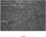
- Fig. 5 depicts the bending effect under variable applied fields up to 500 Oe for a particular composition of metallic core of single phase microwire and two compositions of the shell (Co and FeNi).
- the Fe 77.5 B 15 Si 7.5 alloy was considered for the metallic nucleus of single phase microwire with diameter of 10.2 ⁇ m, and 25 ⁇ m for the total diameter.
- the thickness of partially covering external shell is the same for Co and FeNi, that is, 300 nm.
- the length of microwires was 2 cm.
- the left positions correspond to the situation without applied magnetic field.
- the white arrows to the right indicate the position of microwire at maximum magnetic field of 500 Oe applied along the microwire axis. All the positions of microwires between black dashed and white arrows are related to the intermediate values of the magnetic fiend ranging from 0 to 500 Oe. As schematically indicated in Figure 1b the microwires undergo a bending deformation which is proportional to the amplitude of the DC axial magnetic field.
- the magnetostriction coefficients for FeNi and Co are different: nearly zero for FeNi and negative for Co.
- the bending deformation amplitude, 209.2 ⁇ m is larger than the one, 186.4 ⁇ m, observed for the biphase microwire with FeNi shell. This fact allows one to conclude that the enhanced deflection effect is originated by the combination of the positive magnetostriction of the metallic nucleus and the negative magnetostriction of the external shell.
- microactuator based on bimagnetic coated core/shell microwires with asymmetric external shell has the following original aspects.
- the use of soft magnetic materials gives the possibility to avoid or at least significantly reduce in a controlled manner the otherwise strong residual stray field generated by hard magnetic materials at remanence which has an additional influence on the manipulated object and reduces the displacement accuracy.
- the microwire is magnetically bistable, that means that only two magnetic states are stable corresponding to the two axial directions along the microwire axis.
- the value of the magnetic field required for switching of magnetic state is very small (e.g., down to 20 A/m).
- the metallic core of the microwire is made of an alloy material with nearly zero magnetostriction (CoFe, or CoFeNi-based alloys) or negative magnetostriction (Co-based alloys)
- the reversal magnetization process has a nearly non-hysteretic behavior. This fact allows one to avoid the appearance of any strong residual field, which appears in the case of magnetic tweezers using permanent magnets, and enhance the precision of the microactuator based on bimagnetic coated core/shell microwires with asymmetric external shell.
- microactuator based on bimagnetic coated core/shell microwires with asymmetric external shell can be used in two operating modes.
- This mode can be used for the control of biological objects through attached specially functionalized magnetic particles, when the direct mechanical contact can be harmful to living cultures.
Landscapes
- Chemical & Material Sciences (AREA)
- Engineering & Computer Science (AREA)
- Nanotechnology (AREA)
- Health & Medical Sciences (AREA)
- Life Sciences & Earth Sciences (AREA)
- General Health & Medical Sciences (AREA)
- Molecular Biology (AREA)
- Crystallography & Structural Chemistry (AREA)
- Analytical Chemistry (AREA)
- Computer Hardware Design (AREA)
- Microelectronics & Electronic Packaging (AREA)
- Soft Magnetic Materials (AREA)
Abstract

Description
- The overall objective of the invention is a microactuator based, or making use, of a hybrid or composite sensing element.
- A particular feature is the asymmetric character of the composite sensing element of the microactuator. It takes advantage of the particular response to an applied magnetic field of a sensing element formed by a multilayer bimagnetic coated core/shell microwire where each magnetic phase exhibits different magnetostrictive character. The active phases are: i) an internal metallic magnetostrictive core, and ii) an external coating metallic magnetostrictive shell.
- A relevant concept is that the external shell is asymmetric in the sense that it covers only partly the internal core.
- The microactuator based on the bimagnetic coated core/shell microwires with asymmetric external shell can be used to control the positioning and manipulation of nano to micro magnetic and nonmagnetic objects in two modes namely, contact and non-contact modes. Its application covers areas as physics, chemistry and nanotechnology, but also in biochemistry, biology and pharmaceutics where the physical touch are often harmful to living cultures.
- Distinctive features of the microacuator based on the bimagnetic coated core/shell microwires with asymmetric external shell from similar devices, such as magnetic tweezers, are:
- i) the possibility to reach absence of any residual or remanent field for microwires with selected alloy composition, which has an additional influence on the manipulated object and reduces the displacement accuracy; and
- ii) a larger size range of the manipulated objects (up to tens of microns) and larger spatial workspace.
- The accurate manipulation of miniaturized objects is essential for the development of novel advanced technologies at the nano and microscales.
- Nowadays, advanced devices for such manipulation make use of different instruments including optical and magnetic tweezers, piezoelectrics, computer disk drive heads or atomic force microscopy (AFM) [K.C. Neurman, A. Nagy, "Single-molecule force spectroscopy: optical tweezers, magnetic tweezers and atomic force microscopy", Nature Methods, Vol. 5, 6, (2008) 491-505].
- Each of these systems provides the unique opportunities for control and study of nano- and micro- objects. For example, AFM allows one to manipulate objects of atomic size and image them up to a few microns. The forces that could be applied to the objects range from 10 to 1000 pN [D. Dulin, J. Lipfert, M. Ch. Moolman, N. H. Dekker, "Studying genomic processes at the single-molecule level: introducing the tools and applications", Nature Review Genetics, Vol. 14, 1, (2013) 9-22].
- The optical trap can capture the objects ranging in size from 0.25 to 10 µm [K. Svoboda, S. Block, "Optical trapping of metallic Raleigh particles", Optic letters 19, (1994) 930-932] and act with force up to 100 pN [R. Litvinov, H. Shuman, J. Benette, J. Weisel, "Binding strength and activation state of single fibrinogenintegrin pairs on living cells", Proceedings of the National Academy of Sciences 99 (2002), 7426-7431].
- However, optical tweezers can be used only for partially transparent particles in a liquid. Some types of mechanical microactuators use different physical effects such as electromagnetism, electrostatics, piezoelectric force and shape memory effect to generate the movement and control the gripping force. The microactuator, based on piezoelectric effect, can achieve a force of 20 mN to grab and move the objects [Geßner, T., "Recent Progress of Microactuators" in: Proc. 7th Int. Conf. New Actuators (Bremen, 19-21 June 2000) Bremen: ASCO-Druck 2000, pp 62-70]. Shape memory alloy microactuators allow to manipulate objects up to 180 micron size with a maximum gripping force of 17 mN [Just, E. et al, "SMA Microgripper with Integrated Antagonism", in: Proc. Transducers '99, 10th Int. Conf. Solid-State Sensors and Actuators (Sendai, Japan, June 7-10 1999) S. 1768-1771]. Its state can be controlled by electrical heating above the phase transition temperature.
- Magnetic tweezers have several advantages as compared with other types of tweezers: no restrictions on transparency and the particle size, as in optical tweezers, and they allow the operation in various environments (gas, liquid, vacuum) [J. Zlatanova, K. van Holde, "Single-Molecule Biology: What Is It and How Does It Work", Molecular Cell 24, 317-329, November 3 (2006), 317-329]. However, in some cases the presence of residual field does not allow to stop the influence on the magnetic particle immediately after current interruption.
- A different family of devices makes use of hybrid elements composed of units with specific different response to given agent (e.g. magnetic field). Microactuators are commonly designed in a planar configuration. One of such microactuators is a bilayer system consisting of magnetostrictive and non-magnetic counter layers. The operation principle is based on the magneto-elastic effect (e.g., the sensitivity of the permeability of the bilayer to bending and temperature). The sensitivity, determined as the ratio of the permeability to its initial value, reaches 70%. Such bilayer system can be used as a continuous non-disturbing monitoring of blood pressure changes [H. Pfutzner, E. Kaniusas, J. Kosel, L. Mehnen, T. Meydan, M. Vazquez, M. Rhon, A.M. Merlo, and B. Marquardt, Sens. Actuators 129, 154 (2006)].
- Alternative actuators make use of cylindrical symmetry and profit of the uniaxial directional anisotropy. Current magnetic tweezers based on non-magnetic microwires systems allow for the capture of nano- and micro- objects via the magnetic field generated by the electric currents flowing through these wires. The position of the manipulated objects is thus controlled by changing in a controlled way the value of the current. Applied force to the manipulated objects reaches 3 pN [V. Bessalova, N. Perov, V. Rodionova, New approaches in the design of magnetic tweezers-current magnetic tweezers, Journal of Magnetism and Magnetic Materials (2016); doi:10.1016/j.jmmm.2016.03.038].
- Amorphous magnetic microwires exhibit an outstanding magnetic behavior when submitted to longitudinal magnetic fields which is a consequence of their amorphous structure and the mechanical stresses quenched-in during their fabrication by ultrarapid solidification. Microwires made of high positive magnetostriction alloy (e.g., FeSiB) are relevant because of their bistable magnetic behavior characterized by a giant Barkhausen jump originating in the propagation of a single domain wall. Those with negative magnetostriction (e.g., CoSiB) exhibit nearly constant susceptibility until reaching magnetic saturation and reduced coercivity and remanence. In turn, amorphous microwires with vanishing magnetostriction (e.g., CoFeSiB and CoFeNiSiB) show very high susceptibility and giant magneto impedance effect. Description and analysis of the general properties of glass-coated microwires can be found elsewhere [A. Zhukov and V. Zhukova, "Magnetic Properties and Applications of Ferromagnetic Microwires with Amorphous and Nanocrystalline Structure" (Hauppauge, NY: Nova Science Publishers, Inc., 2009), 162].
- A novel family of bimagnetic multilayer microwires with additional properties arising from the presence of the two magnetic phases was recently introduced. They contain an internal magnetic nucleus and external magnetic shell. Eventually, an intermediate insulating glass layer is present (e.g., in the case of glass-coated based bimagnetic microwires). Such bimagnetic microwires are fabricated by combined ultrarapid solidification, sputtering and electrodeposition techniques [K. Pirota, M. Hernandez-Velez, D. Navas, A. Zhukov and M. Vazquez, Adv. Funct. Mater. 14, 266 (2004); J. Torrejón, G. Infante, G. Badini-Confalonieri, K.R. Pirota and M. Vázquez, "Electroplated Bimagnetic Microwires: From Processing to Magnetic Properties and Sensor Devices", The Journal of The Minerals, Metals & Materials Society (TMS), (2013) DOI: 10.1007/s11837-013-0614-3].
- Bimagnetic multilayer microwires have been proposed earlier where the external magnetic shell covers completely the internal nucleus [
WO2007/054602 ;WO2011/009971 ]. - It is a first object of the present invention a microactuator based on bimagnetic coated core/shell microwires with asymmetric external shell having at least one composite one-dimensional sensing element which comprises:
- an internal metallic magnetostrictive core;
- an external coating metallic magnetostrictive shell.
- The materials of the internal metallic magnetostrictive core and the external coating metallic magnetostrictive shell display either opposite magnetostriction sign or the same magnetostriction sign with different values of the respective magnetostriction coefficient.
- The characterizing feature of the microactuator is that the external coating metallic magnetostrictive shell covers asymmetricaly only partly the internal core.
- Cross-section asymmetry is the essential feature.
- The internal metallic magnetostrictive core and the external coating metallic magnetostrictive shell may be coaxial depending on the geometrical configuration of the sensing element.
- Through the present description, the internal metallic core will be also referred to as nucleus.
- In a preferred embodiment, the materials of the internal metallic magnetostrictive core and the external coating metallic magnetostrictive shell have the same magnetostriction sign with values of the respective magnetostriction coefficient which differ by at least a factor of 10, more preferably the materials of the internal metallic magnetostrictive core and the external coating metallic magnetostrictive shell have the same magnetostriction sign with magnetostriction coefficient values differing in a factor ranging from 10 to 1000.
- The at least one composite one-dimensional sensing element of the microactuator presents a geometrical configuration selected from cylindrical, spheroidal and ellipsoidal, preferably the at least one composite one-dimensional sensing element is cylindrical and the external coating metallic magnetostrictive shell covers concentrically and asymmetrically only partly the internal core.
- The relevant dimension may vary depending from the selected geometrical configuration: diameter in cylindrical configuration and major axis in ellipsoidal configuration.
- In another preferred embodiment, the internal metallic magnetostrictive core is coated by an insulating glass cover and the external coating metallic magnetostrictive shell covers only partly asymmetricaly the internal metallic magnetostrictive core with the insulating glass cover.
- In further preferred embodiments:
- the internal metallic magnetostrictive core is formed by a metallic ferromagnetic alloy and has a relevant dimension ranging from 0.6 to 30 µm
- the metallic ferromagnetic alloy forming the internal metallic magnetostrictive core has amorphous structure and comprises:
- 65% to 85% in atomic percentage of magnetogen elements selected from Fe, Co and Ni and combinations thereof.
- 15% to 35% in atomic percentage of metalloid elements selected from Si, B and C.
- the metallic ferromagnetic alloy forming the internal metallic magnetostrictive core additionally comprises other non-magnetic elements selected from Al, Cu, Nb, Mn, Cr, Mo and combinations thereof in an amount less than 5% in atomic percentage to keep the amorphous structure of the alloy.
- In embodiments including an insulating glass cover, its thickness ranges from 2 µm to 30 µm.
- Regarding the external coating metallic magnetostrictive shell, in one preferred embodiment it is formed by a metallic ferromagnetic alloy and has a thickness ranging from 0.03 to 5 µm.
- In reference to the characterizing feature, the external coating metallic magnetostricitve shell covers the internal core in a range from 20% to 80% of its outer surface. In further preferred embodiments the coverage of the internal core by the external coating metallic magnetostricitve shell ranges from 30% to 70%, more preferably from 40% to 60% and even more preferably 50%.
- The metallic ferromagnetic alloy forming the external coating metallic magnetostrictive shell comprises magnetogen elements selected from Fe, Co and Ni and combinations thereof. Preferably, the metallic ferromagnetic alloy of the external coating metallic magnetostrictive shell is a metallic alloy based on CoFe elements.
- In another further preferred embodiment, a metallic nanolayer is located on the internal metallic magnetostrictive core, whereon the external coating metallic magnetostrictive shell is deposited. Alternatively, the metallic nanolayer is located on the insulating glass cover whereon the external coating metallic magnetostrictive shell is deposited.
- Preferably, the metallic nanonolayer is made of a noble metal, more preferably the noble metal is gold.
- Another object of the invention is the use of the microactuator based on bimagnetic coated core/shell microwires with asymmetric external shell either with magnetic objects or with non magnetic objects.
- The interaction with magnetic objects includes:
- approaching the microactuator to the magnetic object
- applying an external magnetic field to the sensing element of the microactuator
- capture of the stay field generated at the end of the sensing element of the microactuator by the magnetic object
- bending of the sensing element of the microactuator
- displacement in two or three dimensions of the magnetic object captured by the stray field at the end of the sensing element.
- The interaction with non magnetic objects includes:
- contacting the microactuator with the non magnetic object
- applying an external magnetic field to the sensing element of the microactuator
- bending of the sensing element of the microactuator
- mechanical displacement in two or three dimensions of the non magnetic object
-
-
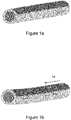
Figure 1 : Scheme of the bimagnetic microwire with asymmetric external shell (a), and its bending under the action of magnetic field, H (b). Arrows in the microwire denote the magnetostrictive bending stress. -
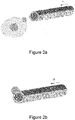
Figure 2 : Scheme of the bimagnetic microwire, which bends under the action of magnetic field, H, generating (a) a magnetic force on a magnetic nanoparticle (non-contact mode), (b) a mechanical force on a non-magnetic object (contact mode) -
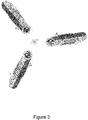
Figure 3 : Scheme of the microactuator with tri-microwire design to control the position of the manipulated object in two dimensions. -
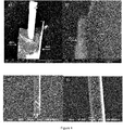
Figure 4 : SEM-images of FeSiB glass-coated microwire coated asymmetrically by a sputtered shell (a) with detail of the shell's thickness (b) (using Ultra-high resolution low-vacuum FEI Nova NanoSEM 230 microscope); visualization of the core/shell microwires with asymmetric external shell (c) and (d): the glass is the illuminated brighter side and the shell is dark side of the image (using SEM JEOL). -
Figure 5 : Composed image showing the bending of different microwires under increasing applied magnetic field up to a maximum of 500 Oe: single-phase FeSiB glass-coated microwire (left), and biphase microwires with Co (middle) and FeNi (right) external shells. - The proposed invention is a microactuator based on bimagnetic coated core/shell microwires with asymmetric external shell as described above for the final manipulation of nano- and micro- objects.
- Their main characteristics involve:
- i) Biphase character,
- ii) different magnetostriction sign or different magnetostriction coefficient
- iii) It profits of the different response of each phase to a given external agent, such as a magnetic field
- iv) The asymmetric partial coating of the external shell confers the microactuator specific differential characteristics.
- Particularly, the external coating metallic magnetostictive shell covers only partly the internal magnetostrictive core, which is the basic concept of the new approach introduced in this patent application. The final objective searched by the partial coating is to introduce a particular asymmetry in the microwire with given geometry (
Fig. 1 a) . - The main working element of the proposed microactuator are thus the bimagnetic coated core/shell microwires with asymmetric external shell. The ferromagnetic materials of the metallic core and external shell exhibit opposite sign or eventually different values of the magnetostriction coefficient (i.e., positive, or negative, irrespectively), which enhances significantly the magnetoelastic response of the bi-phase microwire. Consequently, under an applied longitudinal magnetic field, the internal core will elongate while the external shell will shrink, or vice versa. This leads to the bending of the microwire that is, to an effective shift of the microwire end as schematically shown in
Fig. 1 b. - It is possible to manipulate the positioning of the microwire end by controlling the applied magnetic field. There are two different modes of manipulation depending on the magnetic nature of the objects:
- I) To capture the magnetic nano- and micro- objects by the stray fields created at the end of microwire and move the objects for the required distance (
Fig. 2a , non-contact mode); - II) To manipulate the position of non-magnetic objects by direct mechanical motion of the microwire end (
Fig. 2b , contact mode). - The manipulation of a magnetic nano- or micro magnetic object in two dimensions (X and Y axis) can be also achieved making use of a tri-microwire design (
Fig. 3 ). Here, the stray field generated at the end of each magnetized asymmetric microwire is tailored by the current of a surrounding tiny coil. The magnetized microwire actually acts as a small electromagnet, and the appropriate control of stray fields from each microwire determines the total stray field in the region between microwires. - Thus, the microactuator based on the bimagnetic coated core/shell microwires with asymmetric external shell can be used in two modes - non-contact and contact - that allows one to apply it not only in such areas as physics, chemistry and nanotechnologies, but also in biochemistry, biology and pharmaceutics where the physical touch are often harmful to living cultures.
- One distinctive feature of the microacuator based on the bimagnetic coated core/shell microwires with asymmetric external shell, from its direct analogue (magnetic tweezers), is the possibility to achieve absence of any residual field, provided that specific composition and parameters of the biphase microwire are carefully selected. Residual magnetic field has an additional influence on the manipulated object and reduces the displacement accuracy. Additionally, residual fields require a larger size range of the manipulated objects (up to tens of microns) and larger spatial workspace.
- The preparation of one of the embodiments of the microactuator is carried out by two alternative processes.
- The first one is:
- a1) Ultrarapid solidification process of fabrication of the internal magnetic core coated by insulating glass-cover (modified Taylor-Ulitovsky method) (e.g. Pyrex).
- a2) Sputtering of a metallic nanolayer onto the mentioned glassy cover
- a3) Electrodeposition of a metallic ferromagnetic external shell coaxial with the core. This external shell or concentric microtube has been developed previously to cover symmetrically and completely the internal core. The invention consists here to electrodeposit the external shell covering only partially the core, having a nearly axial shape as indicated schematically in
Fig. 1a . In order to achieve the partial coating of the internal core, a mask is employed which determines the shape of the external shell. This first alternative allows the growth of a micrometric thick external shell. A challenge is the proper coating of the mask. - The second one is:
- b1) Ultrarapid solidification process of fabrication of the internal magnetic core coated by insulating glass-cover (modified Taylor-Ulitovsky method) (e.g. Pyrex).
- b2) Sputtering of the external magnetic metallic shell directly onto the mentioned glassy cover. The invention consists here to sputter the external shell covering only partially the core, having a nearly axial shape as indicated schematically in
Fig. 1a . To achieve that goal the ends of the single phase microwire, carefully cleaned in alcohol, are fixed to the holder inside the chamber allowing only the sputtering on the partial lateral side of the microwire. This second alternative allows for the growth of hundreds of nanometer thick external shell. A challenge here is the limited thickness of the external shell. - In both cases, the composition of the internal core and external shell is designed to exhibit different magnetic behavior namely, different signs of magnetostriction constant or same magnetostriction sign but different values of magnetostriction coefficient. That promotes the required bending of the microwire when submitted to applied magnetic field as schematically shown in
Fig. 1 b. - To avoid remanent stray fields, only a vanishing or negative magnetostriction core can be employed using the design in
Fig. 3 where the magnetic state is controlled by the current in the tiny coils. - In the following examples the preparation of the microactuator with specific details is described. First, the preparation of the bimagnetic coated core/shell microwires with asymmetric external shell is described.
- As previously indicated, for the two alternatives the internal core consists of an amorphous ferromagnetic glass-coated microwire prepared by quenching and drawing technique (modified Taylor-Ulitovsky method).
- For the final purpose of the invention, one important magnitude is the magnetostriction which is determined mainly by the alloy composition. In these embodiments, three specific alloys with different magnetostriction constant are considered:
- a) Fe75Si15B10 (with elevated and positive magnetostriction, λs ≈ +30x10-6)
- b) (Co0.94Fe0.06)75Si15B10 (with vanishing magnetostriction, λs ≈ ±0.1x10⁻⁶), and
- c) C075Si15B10 (with moderate negative magnetostriction, λs ≈ -1x10⁻⁶).
- The manufacturing of the external magnetic shell requires its asymmetric covering of the internal magnetic phase. There are two alternative ways:
- The first one comprises first the sputtering of a metallic nanolayer of gold (20 to 50 nm thick) followed by the electrodeposition of the external shell. The general procedure of fabrication of the external magnetic shell is explained in detail for example in M. Vazquez, "Advanced Magnetic Microwires" in: Handbook of Magnetism and Advanced Magnetic Materials, vol. 4 Wiley, Chichester, UK, (2007) pp. 2193. Importantly for the purpose of the invention is the magnetostrictive character of the external shell which microstructure is typically polycrystalline. Two kinds of external shells with different magnetic character are used for these embodiments:
- Fe19Ni81 (with ultrasoft magnetic character and vanishing magnetostriction, λ ≈ ±0.1x10⁻⁶), and Co or Co90Ni10 (with magnetically harder character and negative magnetostriction coefficient λ ≈ -30x10-6).
- The inventive feature of the manufacturing procedure is the suitable mask process to cover the external part of the nanolayer of gold that allows for the electroplating of asymmetrical external shell. Such Au nanolayer serves as an electrode for the subsequent electroplating growth of the external second magnetic phase. Magnetically soft FeNi alloys and magnetically hard Co or CoNi alloys (saturation magnetostriction of the latter also has a variety of values) are selected for the electrodeposited ferromagnetic shell. Using electrodeposition it is possible to prepare both fully and partially covered microwire. For manufacturing of bimagnetic coated core/shell microwires with asymmetric external shell by electrodeposition, the protective layer is applied, which covers 50% of the microwire external surface along the axis. This layer avoids the deposition on the covered part of microwire thereby allowing the formation of a partially applied shell. The protective layer can be removed after electrodeposition. The thickness of ferromagnetic shell is controlled by electrodeposition time and current density and ranges from 0.1 to 5 µm.
- The second alternative process to grow the asymmetric external shell consists of the straightforward sputtering of the metallic shell once the glass-coated microwire was produced. The sputtering process has been performed using a magnetron sputtering. To prepare bimagnetic coated core/shell microwires with asymmetric external shell using magnetron sputtering, first the ends of the amorphous ferromagnetic single phase microwires, previously cleaned in alcohol, are fixed on a holder which is subsequently put in the sputtering chamber. The fixed ends help to have a good contact between microwire and holder, so that only 50% of the microwire external surface is sputtered. Then using the targets of suitable magnetostrictive materials sputtering is performed to grow a 30 to 2000 nm thick film on the surface of the microwire.
- In
figures 4 a glass-coated microwire partially covered by a Fe19Ni81 sputtered shell 260 nm thick can be observed. - A bimagnetic coated core/shell microwire with asymmetric external shell is selected with the following characteristics:
- Nucleus: FeSiB (soft character and positive magnetostriction coefficient) and FeCo-based or FeCoNi-based (ultrasoft character and vanishing magnetostriction coefficient) glass-coated microwires with diameters of the metallic nucleus ranging from 1 to 30 µm and total diameter of the glass-coated microwire from 5 to 60 µm.
- Shell: FeNi (magnetically ultrasoft with near zero magnetostriction coefficient), and Co and CoNi (magnetically harder with negative magnetostriction coefficient) shell with thickness from 0.03 to 5 µm coaxially and asymmetrically covering partially the nucleus.
- So, the total diameter of bimagnetic wire is from 5 to 70 µm.
- The microwires - single-phase, and biphase partially covered by FeNi, Co or CoNi asymmetric external shells have been submitted to applied field along the longitudinal direction, that is, parallel to the microwire axis. As an example,
Fig. 5 depicts the bending effect under variable applied fields up to 500 Oe for a particular composition of metallic core of single phase microwire and two compositions of the shell (Co and FeNi). The Fe77.5B15Si7.5 alloy was considered for the metallic nucleus of single phase microwire with diameter of 10.2 µm, and 25 µm for the total diameter. The thickness of partially covering external shell is the same for Co and FeNi, that is, 300 nm. The length of microwires was 2 cm. - The left positions (see
Figure 5 ), indicated by the black dashed arrows, correspond to the situation without applied magnetic field. The white arrows to the right indicate the position of microwire at maximum magnetic field of 500 Oe applied along the microwire axis. All the positions of microwires between black dashed and white arrows are related to the intermediate values of the magnetic fiend ranging from 0 to 500 Oe. As schematically indicated inFigure 1b the microwires undergo a bending deformation which is proportional to the amplitude of the DC axial magnetic field. - From
Figure 5 it can be concluded that all the microwires (single and biphase) are bent by applying a magnetic field. The bending properties of the single phase microwire are associated with non-uniform distribution of the internal stresses that arise during the manufacturing procedure and due to the different values of the thermal expansion coefficients for glass and metal. These non-uniform distributed stresses cause that the microwire undergoes different deformations at local positions of the microwire. The amplitude of bending in the case of single phase microwire is 47.3 µm at maximum applied magnetic field of 500 Oe. The presence of the external shell, the magnetostriction coefficient of which is different, leads to the additional bending force, and hence, to larger bending deformation. - The magnetostriction coefficients for FeNi and Co are different: nearly zero for FeNi and negative for Co. As observed in
Figure 5 in case of Co external shell, the bending deformation amplitude, 209.2 µm, is larger than the one, 186.4 µm, observed for the biphase microwire with FeNi shell. This fact allows one to conclude that the enhanced deflection effect is originated by the combination of the positive magnetostriction of the metallic nucleus and the negative magnetostriction of the external shell. - The microactuator based on bimagnetic coated core/shell microwires with asymmetric external shell has the following original aspects.
- The use of soft magnetic materials gives the possibility to avoid or at least significantly reduce in a controlled manner the otherwise strong residual stray field generated by hard magnetic materials at remanence which has an additional influence on the manipulated object and reduces the displacement accuracy. In the case of amorphous ferromagnetic alloy, based on Fe, with positive magnetostriction coefficient, the microwire is magnetically bistable, that means that only two magnetic states are stable corresponding to the two axial directions along the microwire axis. The value of the magnetic field required for switching of magnetic state (reversal magnetization occurs by a single giant Barkhausen jump) is very small (e.g., down to 20 A/m).
- In turn, when the metallic core of the microwire is made of an alloy material with nearly zero magnetostriction (CoFe, or CoFeNi-based alloys) or negative magnetostriction (Co-based alloys), the reversal magnetization process has a nearly non-hysteretic behavior. This fact allows one to avoid the appearance of any strong residual field, which appears in the case of magnetic tweezers using permanent magnets, and enhance the precision of the microactuator based on bimagnetic coated core/shell microwires with asymmetric external shell.
- The microactuator based on bimagnetic coated core/shell microwires with asymmetric external shell can be used in two operating modes.
- a) Non-contact mode: Magnetic objects can be captured by the stray fields generated at the end of the microwire when it is magnetized. Then, the captured magnetic objects, sticking at the end or located within a certain distance from the microwire can be displaced following the end of the microwire while bending. The magnitude of bending is controlled by the value of the external magnetic field applied along the microwire axis.
- This mode can be used for the control of biological objects through attached specially functionalized magnetic particles, when the direct mechanical contact can be harmful to living cultures.
- b) Contact mode: The microactuator based on bimagnetic coated core/shell microwires with asymmetric external shell also allows manipulating non-magnetic objects. In this case, the object can be displaced mechanically when the movement of the microwire end directly causes the motion of the manipulated object.
Claims (19)
- Microactuator based on bimagnetic coated core/shell microwires with asymmetric external shell having at least one composite one-dimensional sensing element which comprises:- an internal metallic magnetostrictive core- an external coating metallic magnetostrictive shellthe materials of said internal metallic mangnetostrictive core and said external coating metallic magnetostrictive shell displaying either opposite magnetostriction sign or the same magnetostriction sign with different values of the respective magnetostriction coefficient,
characterized in that the external coating metallic magnetostrictive shell covers asymmetrically only partly the internal core. - Microactuator based on coated core/shell microwires with asymmetric external shell according to claim 1, wherein the materials of the internal metallic magnetostrictive core and the external coating metallic magnetostrictive shell have the same magnetostriction sign with values of the respective magnetostriction coefficient which differ by at least a factor of 10.
- Microactuator based on coated core/shell microwires with asymmetric external shell according to claim 2, wherein the materials of the internal metallic magnetostrictive core and the external coating metallic magnetostrictive shell have the same magnetostriction sign with magnetostriction coefficient values differing in a factor ranging from 10 to 1000.
- Microactuator based on coated core/shell microwires with asymmetric external shell according to anyone of claims 1 and 3, wherein the at least one composite one-dimensional sensing element presents a geometrical configuration selected from cylindrical, spheroidal and ellipsoidal.
- Microactuator based on coated core/shell microwires with asymmetric external shell according to claim 4, wherein the at least one composite one-dimensional sensing element is cylindrical and the external coating metallic magnetostrictive shell covers concentrically and asymmetrically only partly the internal core.
- Microactuator based on bimagnetic coated core/shell microwires with asymmetric external shell according to anyone of claims 1 to 5 wherein the internal metallic magnetostrictive core is coated by an insulating glass cover and the external coating metallic magnetostrictive shell covers only partly asymmetrically the internal metallic magnetostrictive core with the insulating glass cover.
- Microactuator based on bimagnetic coated core/shell microwires with asymmetric external shell according to anyone of claims 1 to 6, wherein the internal metallic magnetostrictive core is formed by a metallic ferromagnetic alloy and has a relevant dimension ranging from 0.6 to 30 µm.
- Microactuator based on bimagnetic coated core/shell microwires with asymmetric external shell according to claim 7, wherein the metallic ferromagnetic alloy has amorphous structure and comprises:- 65% to 85% in atomic percentage of magnetogen elements selected from Fe, Co and Ni and combinations thereof,- 15% to 35% in atomic percentage of metalloid elements selected from Si, B and C.
- Microactuator based on bimagnetic coated core/shell microwires with asymmetric external shell according to claim 8, wherein the metallic ferromagnetic alloy additionally comprises other non-magnetic elements selected from Al, Cu, Nb, Mn, Cr, Mo and combinations thereof in an amount less than 5% in atomic percentage to keep the amorphous structure of the alloy.
- Microactuator based on bimagnetic coated core/shell microwires with asymmetric external shell according to anyone of claims 6 to 9, wherein the insulating glass cover has a thickness ranging from 2 µm to 30 µm.
- Microactuator based on bimagnetic coated core/shell microwires with asymmetric external shell according to anyone of claims 1 to 10, wherein the external coating metallic magnetostrictive shell is formed by a metallic ferromagnetic alloy and has a thickness ranging from 0.03 to 5 µm.
- Microactuator based on bimagnetic coating core/shell microwires with asymmetric external shell according to claim 11 wherein the external coating metallic magnetostrictive shell covers the internal core in a range from 20% to 80% of its outer surface.
- Microactuator based on bimagnetic coating core/shell microwires with asymmetric external shell according to claims 11 and 12, wherein the metallic ferromagnetic alloy of the external coating metallic magnetostrictive shell comprises magnetogen elements selected from Fe, Co and Ni and combinations thereof.
- Microactuator based on bimagnetic coating core/shell microwires with asymmetric external shell according to claim 13, wherein the external coating metallic magnetostrictive shell is a metallic alloy based on CoFe elements.
- Microactuator based on bimagnetic coating core/shell microwires with asymmetric external shell according to anyone of claims 1 to 5, wherein a metallic nanolayer is located on the internal metallic magnetostrictive core, whereon the external coating metallic magnetostrictive shell is deposited.
- Microactuator based on bimagnetic coating core/shell microwires with asymmetric external shell according to anyone of claims 6 to 14, wherein a metallic nanolayer is located on the insulating glass cover whereon the external coating metallic magnetostrictive shell is deposited.
- Microactuator based on bimagnetic coating core/shell microwires with asymmetric external shell according to claims 15 or 16, wherein the metallic nanolayer is a noble metal nanolayer.
- Use of a microactuator based on bimagnetic coated core/shell microwires with asymmetric external shell as defined in claims 1 to 17 with magnetic objects which includes:- approaching the microactuator to the magnetic object- applying an external magnetic field to the sensing element of the microactuator- capture of the stray field generated at the end of the sensing element of the microactuator by the magnetic object- bending of the sensing element of the microactuator- displacement in two or three dimensions of the magnetic objects captured by the stray field at the end of the sensing element of the microactuator.
- Use of a microactuator based on bimagnetic coated core/shell microwires with asymmetric external shell as defined in claims 1 to 17 with non magnetic objects which includes:- contacting the microactuator with the non magnetic object- applying an external magnetic field to the sensing element of the microactuator- bending of the sensing element of the microactuator- mechanical displacement in two or three dimensions of the non magnetic object.
Priority Applications (3)
| Application Number | Priority Date | Filing Date | Title |
|---|---|---|---|
| EP17382418.6A EP3422429B1 (en) | 2017-06-30 | 2017-06-30 | Microactuator based on bimagnetic core/shell microwire having asymmetric shell and displacement methods |
| LTEP17382418.6T LT3422429T (en) | 2017-06-30 | 2017-06-30 | Microactuator based on bimagnetic core/shell microwire having asymmetric shell and displacement methods |
| ES17382418T ES2844948T3 (en) | 2017-06-30 | 2017-06-30 | Micro-actuator based on core / shell microthreads with bimagnetic cladding and asymmetric outer sheath and the use thereof |
Applications Claiming Priority (1)
| Application Number | Priority Date | Filing Date | Title |
|---|---|---|---|
| EP17382418.6A EP3422429B1 (en) | 2017-06-30 | 2017-06-30 | Microactuator based on bimagnetic core/shell microwire having asymmetric shell and displacement methods |
Publications (2)
| Publication Number | Publication Date |
|---|---|
| EP3422429A1 true EP3422429A1 (en) | 2019-01-02 |
| EP3422429B1 EP3422429B1 (en) | 2020-10-21 |
Family
ID=59381224
Family Applications (1)
| Application Number | Title | Priority Date | Filing Date |
|---|---|---|---|
| EP17382418.6A Not-in-force EP3422429B1 (en) | 2017-06-30 | 2017-06-30 | Microactuator based on bimagnetic core/shell microwire having asymmetric shell and displacement methods |
Country Status (3)
| Country | Link |
|---|---|
| EP (1) | EP3422429B1 (en) |
| ES (1) | ES2844948T3 (en) |
| LT (1) | LT3422429T (en) |
Citations (3)
| Publication number | Priority date | Publication date | Assignee | Title |
|---|---|---|---|---|
| DE19510250C1 (en) * | 1995-03-21 | 1996-05-02 | Siemens Ag | Magnetostrictive thin film actuator as drive for miniaturised valve, bending element, or pump |
| WO2007054602A1 (en) | 2005-11-11 | 2007-05-18 | Consejo Superior De Investigaciones Científicas | Multifunctional sensor based on multilayer magnetic microwires with magnetoelastic coupling |
| WO2011009971A1 (en) | 2009-07-20 | 2011-01-27 | Consejo Superior De Investigaciones Científicas (Csic) | Bimetallic magnetic wires with helical anisotropy, method for manufacturing same, and uses thereof |
-
2017
- 2017-06-30 ES ES17382418T patent/ES2844948T3/en active Active
- 2017-06-30 LT LTEP17382418.6T patent/LT3422429T/en unknown
- 2017-06-30 EP EP17382418.6A patent/EP3422429B1/en not_active Not-in-force
Patent Citations (3)
| Publication number | Priority date | Publication date | Assignee | Title |
|---|---|---|---|---|
| DE19510250C1 (en) * | 1995-03-21 | 1996-05-02 | Siemens Ag | Magnetostrictive thin film actuator as drive for miniaturised valve, bending element, or pump |
| WO2007054602A1 (en) | 2005-11-11 | 2007-05-18 | Consejo Superior De Investigaciones Científicas | Multifunctional sensor based on multilayer magnetic microwires with magnetoelastic coupling |
| WO2011009971A1 (en) | 2009-07-20 | 2011-01-27 | Consejo Superior De Investigaciones Científicas (Csic) | Bimetallic magnetic wires with helical anisotropy, method for manufacturing same, and uses thereof |
Non-Patent Citations (16)
| Title |
|---|
| A. ZHUKOV; V. ZHUKOVA: "Magnetic Properties and Applications of Ferromagnetic Microwires with Amorphous and Nanocrystalline Structure", 2009, NOVA SCIENCE PUBLISHERS, INC., pages: 162 |
| D. DULIN; J. LIPFERT; M. CH. MOOLMAN; N. H. DEKKER: "Studying genomic processes at the single-molecule level: introducing the tools and applications", NATURE REVIEW GENETICS, vol. 14, no. 1, 2013, pages 9 - 22 |
| GEFLNER, T.: "Proc. 7th Int. Conf. New Actuators", 19 June 2000, ASCO-DRUCK, article "Recent Progress of Microactuators", pages: 62 - 70 |
| H. PFUTZNER; E. KANIUSAS; J. KOSEL; L. MEHNEN; T. MEYDAN; M. VAZQUEZ; M. RHON; A.M. MERLO; B. MARQUARDT, SENS. ACTUATORS, vol. 129, 2006, pages 154 |
| HONDA T ET AL: "Fabrication of magnetostrictive actuators using rare-earth (Tb,Sm)-Fe thin films", JOURNAL OF APPLIED PHYSICS, vol. 76, no. 10, 15 November 1994 (1994-11-15), pages 6994 - 6999, XP000508876, ISSN: 0021-8979, DOI: 10.1063/1.358067 * |
| IKUNO T ET AL: "Thermally driven nanomechanical deflection of hybrid nanowires", APPLIED PHYSICS LETTERS, vol. 87, no. 21, 213104, 14 November 2005 (2005-11-14), XP012076580, ISSN: 0003-6951, DOI: 10.1063/1.2133919 * |
| J. TORREJON; G. INFANTE; G. BADINI-CONFALONIERI; K.R. PIROTA; M. VAZQUEZ: "Electroplated Bimagnetic Microwires: From Processing to Magnetic Properties and Sensor Devices", THE JOURNAL OF THE MINERALS, METALS & MATERIALS SOCIETY (TMS, 2013 |
| J. ZLATANOVA; K. VAN HOLDE: "Single-Molecule Biology: What Is It and How Does It Work", MOLECULAR CELL, vol. 24, 3 November 2006 (2006-11-03), pages 317 - 329 |
| JUST, E. ET AL.: "Proc. Transducers '99, 10th Int. Conf. Solid-State Sensors and Actuators", 7 June 1999, article "SMA Microgripper with Integrated Antagonism", pages: 1768 - 1771 |
| K. PIROTA; M. HERNANDEZ-VELEZ; D. NAVAS; A. ZHUKOV; M. VAZQUEZ, ADV. FUNCT. MATER., vol. 14, 2004, pages 266 |
| K. SVOBODA; S. BLOCK: "Optical trapping of metallic Raleigh particles", OPTIC LETTERS, vol. 19, 1994, pages 930 - 932 |
| K.C. NEURMAN; A. NAGY: "Single-molecule force spectroscopy: optical tweezers, magnetic tweezers and atomic force microscopy", NATURE METHODS, vol. 5, no. 6, 2008, pages 491 - 505, XP055144881, DOI: doi:10.1038/nmeth.1218 |
| M. VAZQUEZ: "Handbook of Magnetism and Advanced Magnetic Materials", vol. 4, 2007, WILEY, article "Advanced Magnetic Microwires", pages: 2193 |
| R. LITVINOV; H. SHUMAN; J. BENETTE; J. WEISEL: "Binding strength and activation state of single fibrinogenintegrin pairs on living cells", PROCEEDINGS OF THE NATIONAL ACADEMY OF SCIENCES, vol. 99, 2002, pages 7426 - 7431 |
| TORREJÓN J ET AL: "Electroplated Bimagnetic Microwires: From Processing to Magnetic Properties and Sensor Devices", JOURNAL OF THE MINERALS, METALS & MATERIALS SOCIETY, vol. 65, no. 7, 26 April 2013 (2013-04-26), pages 890 - 900, XP035350875, ISSN: 1047-4838, [retrieved on 20130426], DOI: 10.1007/S11837-013-0614-3 * |
| V. BESSALOVA; N. PEROV; V. RODIONOVA: "New approaches in the design of magnetic tweezers-current magnetic tweezers", JOURNAL OF MAGNETISM AND MAGNETIC MATERIALS, 2016 |
Also Published As
| Publication number | Publication date |
|---|---|
| ES2844948T3 (en) | 2021-07-23 |
| EP3422429B1 (en) | 2020-10-21 |
| LT3422429T (en) | 2021-04-12 |
Similar Documents
| Publication | Publication Date | Title |
|---|---|---|
| Gibbs et al. | Magnetic materials for MEMS applications | |
| CN103620435B (en) | Magnetostrictive layer system | |
| Pookat et al. | Evolution of structural and magnetic properties of Co–Fe based metallic glass thin films with thermal annealing | |
| Singh et al. | Magnetic Tb75Fe25 nanoglass for cryogenic permanent magnet undulator | |
| Judy | Magnetic materials for MEMS | |
| EP3422429B1 (en) | Microactuator based on bimagnetic core/shell microwire having asymmetric shell and displacement methods | |
| Flatau et al. | Magnetostrictive Fe-Ga Nanowires for actuation and sensing applications | |
| Ponomareva et al. | A quantitative study of magnetic interactions between a micro-magnet array and individual magnetic micro-particles by scanning particle force microscopy | |
| RU2658108C1 (en) | Micromanipulator based on bi-magnetic microwires with core covered with asymmetric external shell and methods of its use | |
| Mu et al. | High-sensitivity giant magneto-impedance microsensor with grooved grating patterned magnetic films | |
| Xing et al. | Fabrication of magnetic atom chips based on FePt | |
| Dvoretskaya et al. | Laser and thermal control over structure and magnetic properties of PrDy-FeCo-B microwires | |
| Wang et al. | Fabrication of symmetrical meandering NiFe/Cu/NiFe film sensors and study of the effects of field direction and film thickness on giant magnetoimpedance | |
| Choi et al. | Use of a GMR-SV Device Below a Single Coil and Channel to Detect the Deformation Properties of Red Blood Cell Membranes: Choi, Rhee, and Lee | |
| Lim et al. | Formation of induced anisotropy in amorphous Sm–Fe based thin films by field sputtering | |
| Wu et al. | Thermoplastic deformation of ferromagnetic CoFe-based bulk metallic glasses | |
| EP3171189A1 (en) | Procedure and apparatus for measuring a d.c. magnetic field based on magnetostrictive effect in magnetic wires | |
| Moritz et al. | Magnetophoresis Assisted Capillary Assembly of Cobalt Nanorods: A New Source of Permanent Magnets for MEMS | |
| Moritz et al. | Development Of Micro-Magnets For The Electromagnetic Transduction Of MEMS | |
| Gandomzadeh et al. | Magnetostrictive behavior of pure nickel core: A study on the effects of annealing and magnetization using VSM and optical microscopy techniques | |
| Eggers | Surface and Interface Effects of Magnetoimpedance Materials at High Frequency | |
| RU2447527C1 (en) | Method and apparatus for generating magnetic field localised in nanosized region of space | |
| Li et al. | Magnetic Fibers | |
| Korznikova | Domain structures of ultrafine grained ferromagnets achieved by severe plastic deformation or melt quenching | |
| Senoy et al. | Fabrication of thin films and nano columnar structures of Fe-Ni amorphous alloys and modification of its surface properties by thermal annealing and swift heavy ion irradiation for tailoring the magnetic properties |
Legal Events
| Date | Code | Title | Description |
|---|---|---|---|
| PUAI | Public reference made under article 153(3) epc to a published international application that has entered the european phase |
Free format text: ORIGINAL CODE: 0009012 |
|
| STAA | Information on the status of an ep patent application or granted ep patent |
Free format text: STATUS: THE APPLICATION HAS BEEN PUBLISHED |
|
| AK | Designated contracting states |
Kind code of ref document: A1 Designated state(s): AL AT BE BG CH CY CZ DE DK EE ES FI FR GB GR HR HU IE IS IT LI LT LU LV MC MK MT NL NO PL PT RO RS SE SI SK SM TR |
|
| AX | Request for extension of the european patent |
Extension state: BA ME |
|
| STAA | Information on the status of an ep patent application or granted ep patent |
Free format text: STATUS: REQUEST FOR EXAMINATION WAS MADE |
|
| 17P | Request for examination filed |
Effective date: 20190621 |
|
| RBV | Designated contracting states (corrected) |
Designated state(s): AL AT BE BG CH CY CZ DE DK EE ES FI FR GB GR HR HU IE IS IT LI LT LU LV MC MK MT NL NO PL PT RO RS SE SI SK SM TR |
|
| GRAP | Despatch of communication of intention to grant a patent |
Free format text: ORIGINAL CODE: EPIDOSNIGR1 |
|
| STAA | Information on the status of an ep patent application or granted ep patent |
Free format text: STATUS: GRANT OF PATENT IS INTENDED |
|
| INTG | Intention to grant announced |
Effective date: 20200515 |
|
| GRAS | Grant fee paid |
Free format text: ORIGINAL CODE: EPIDOSNIGR3 |
|
| GRAA | (expected) grant |
Free format text: ORIGINAL CODE: 0009210 |
|
| STAA | Information on the status of an ep patent application or granted ep patent |
Free format text: STATUS: THE PATENT HAS BEEN GRANTED |
|
| AK | Designated contracting states |
Kind code of ref document: B1 Designated state(s): AL AT BE BG CH CY CZ DE DK EE ES FI FR GB GR HR HU IE IS IT LI LT LU LV MC MK MT NL NO PL PT RO RS SE SI SK SM TR |
|
| REG | Reference to a national code |
Ref country code: GB Ref legal event code: FG4D |
|
| REG | Reference to a national code |
Ref country code: CH Ref legal event code: EP |
|
| REG | Reference to a national code |
Ref country code: IE Ref legal event code: FG4D |
|
| REG | Reference to a national code |
Ref country code: AT Ref legal event code: REF Ref document number: 1326744 Country of ref document: AT Kind code of ref document: T Effective date: 20201115 |
|
| REG | Reference to a national code |
Ref country code: DE Ref legal event code: R096 Ref document number: 602017025796 Country of ref document: DE |
|
| REG | Reference to a national code |
Ref country code: DE Ref legal event code: R082 Ref document number: 602017025796 Country of ref document: DE Representative=s name: WR SERVICES GMBH, DE |
|
| REG | Reference to a national code |
Ref country code: AT Ref legal event code: MK05 Ref document number: 1326744 Country of ref document: AT Kind code of ref document: T Effective date: 20201021 |
|
| REG | Reference to a national code |
Ref country code: NL Ref legal event code: MP Effective date: 20201021 |
|
| PG25 | Lapsed in a contracting state [announced via postgrant information from national office to epo] |
Ref country code: FI Free format text: LAPSE BECAUSE OF FAILURE TO SUBMIT A TRANSLATION OF THE DESCRIPTION OR TO PAY THE FEE WITHIN THE PRESCRIBED TIME-LIMIT Effective date: 20201021 Ref country code: GR Free format text: LAPSE BECAUSE OF FAILURE TO SUBMIT A TRANSLATION OF THE DESCRIPTION OR TO PAY THE FEE WITHIN THE PRESCRIBED TIME-LIMIT Effective date: 20210122 Ref country code: NO Free format text: LAPSE BECAUSE OF FAILURE TO SUBMIT A TRANSLATION OF THE DESCRIPTION OR TO PAY THE FEE WITHIN THE PRESCRIBED TIME-LIMIT Effective date: 20210121 Ref country code: RS Free format text: LAPSE BECAUSE OF FAILURE TO SUBMIT A TRANSLATION OF THE DESCRIPTION OR TO PAY THE FEE WITHIN THE PRESCRIBED TIME-LIMIT Effective date: 20201021 Ref country code: PT Free format text: LAPSE BECAUSE OF FAILURE TO SUBMIT A TRANSLATION OF THE DESCRIPTION OR TO PAY THE FEE WITHIN THE PRESCRIBED TIME-LIMIT Effective date: 20210222 |
|
| PG25 | Lapsed in a contracting state [announced via postgrant information from national office to epo] |
Ref country code: AT Free format text: LAPSE BECAUSE OF FAILURE TO SUBMIT A TRANSLATION OF THE DESCRIPTION OR TO PAY THE FEE WITHIN THE PRESCRIBED TIME-LIMIT Effective date: 20201021 Ref country code: BG Free format text: LAPSE BECAUSE OF FAILURE TO SUBMIT A TRANSLATION OF THE DESCRIPTION OR TO PAY THE FEE WITHIN THE PRESCRIBED TIME-LIMIT Effective date: 20210121 Ref country code: LV Free format text: LAPSE BECAUSE OF FAILURE TO SUBMIT A TRANSLATION OF THE DESCRIPTION OR TO PAY THE FEE WITHIN THE PRESCRIBED TIME-LIMIT Effective date: 20201021 Ref country code: PL Free format text: LAPSE BECAUSE OF FAILURE TO SUBMIT A TRANSLATION OF THE DESCRIPTION OR TO PAY THE FEE WITHIN THE PRESCRIBED TIME-LIMIT Effective date: 20201021 Ref country code: IS Free format text: LAPSE BECAUSE OF FAILURE TO SUBMIT A TRANSLATION OF THE DESCRIPTION OR TO PAY THE FEE WITHIN THE PRESCRIBED TIME-LIMIT Effective date: 20210221 Ref country code: SE Free format text: LAPSE BECAUSE OF FAILURE TO SUBMIT A TRANSLATION OF THE DESCRIPTION OR TO PAY THE FEE WITHIN THE PRESCRIBED TIME-LIMIT Effective date: 20201021 |
|
| PG25 | Lapsed in a contracting state [announced via postgrant information from national office to epo] |
Ref country code: NL Free format text: LAPSE BECAUSE OF FAILURE TO SUBMIT A TRANSLATION OF THE DESCRIPTION OR TO PAY THE FEE WITHIN THE PRESCRIBED TIME-LIMIT Effective date: 20201021 Ref country code: HR Free format text: LAPSE BECAUSE OF FAILURE TO SUBMIT A TRANSLATION OF THE DESCRIPTION OR TO PAY THE FEE WITHIN THE PRESCRIBED TIME-LIMIT Effective date: 20201021 |
|
| REG | Reference to a national code |
Ref country code: DE Ref legal event code: R097 Ref document number: 602017025796 Country of ref document: DE |
|
| REG | Reference to a national code |
Ref country code: ES Ref legal event code: FG2A Ref document number: 2844948 Country of ref document: ES Kind code of ref document: T3 Effective date: 20210723 |
|
| PG25 | Lapsed in a contracting state [announced via postgrant information from national office to epo] |
Ref country code: CZ Free format text: LAPSE BECAUSE OF FAILURE TO SUBMIT A TRANSLATION OF THE DESCRIPTION OR TO PAY THE FEE WITHIN THE PRESCRIBED TIME-LIMIT Effective date: 20201021 Ref country code: EE Free format text: LAPSE BECAUSE OF FAILURE TO SUBMIT A TRANSLATION OF THE DESCRIPTION OR TO PAY THE FEE WITHIN THE PRESCRIBED TIME-LIMIT Effective date: 20201021 Ref country code: SM Free format text: LAPSE BECAUSE OF FAILURE TO SUBMIT A TRANSLATION OF THE DESCRIPTION OR TO PAY THE FEE WITHIN THE PRESCRIBED TIME-LIMIT Effective date: 20201021 Ref country code: RO Free format text: LAPSE BECAUSE OF FAILURE TO SUBMIT A TRANSLATION OF THE DESCRIPTION OR TO PAY THE FEE WITHIN THE PRESCRIBED TIME-LIMIT Effective date: 20201021 Ref country code: SK Free format text: LAPSE BECAUSE OF FAILURE TO SUBMIT A TRANSLATION OF THE DESCRIPTION OR TO PAY THE FEE WITHIN THE PRESCRIBED TIME-LIMIT Effective date: 20201021 |
|
| PLBE | No opposition filed within time limit |
Free format text: ORIGINAL CODE: 0009261 |
|
| STAA | Information on the status of an ep patent application or granted ep patent |
Free format text: STATUS: NO OPPOSITION FILED WITHIN TIME LIMIT |
|
| PG25 | Lapsed in a contracting state [announced via postgrant information from national office to epo] |
Ref country code: DK Free format text: LAPSE BECAUSE OF FAILURE TO SUBMIT A TRANSLATION OF THE DESCRIPTION OR TO PAY THE FEE WITHIN THE PRESCRIBED TIME-LIMIT Effective date: 20201021 |
|
| 26N | No opposition filed |
Effective date: 20210722 |
|
| PG25 | Lapsed in a contracting state [announced via postgrant information from national office to epo] |
Ref country code: IT Free format text: LAPSE BECAUSE OF FAILURE TO SUBMIT A TRANSLATION OF THE DESCRIPTION OR TO PAY THE FEE WITHIN THE PRESCRIBED TIME-LIMIT Effective date: 20201021 Ref country code: AL Free format text: LAPSE BECAUSE OF FAILURE TO SUBMIT A TRANSLATION OF THE DESCRIPTION OR TO PAY THE FEE WITHIN THE PRESCRIBED TIME-LIMIT Effective date: 20201021 |
|
| PG25 | Lapsed in a contracting state [announced via postgrant information from national office to epo] |
Ref country code: SI Free format text: LAPSE BECAUSE OF FAILURE TO SUBMIT A TRANSLATION OF THE DESCRIPTION OR TO PAY THE FEE WITHIN THE PRESCRIBED TIME-LIMIT Effective date: 20201021 |
|
| PG25 | Lapsed in a contracting state [announced via postgrant information from national office to epo] |
Ref country code: MC Free format text: LAPSE BECAUSE OF FAILURE TO SUBMIT A TRANSLATION OF THE DESCRIPTION OR TO PAY THE FEE WITHIN THE PRESCRIBED TIME-LIMIT Effective date: 20201021 |
|
| REG | Reference to a national code |
Ref country code: CH Ref legal event code: PL |
|
| REG | Reference to a national code |
Ref country code: BE Ref legal event code: MM Effective date: 20210630 |
|
| PG25 | Lapsed in a contracting state [announced via postgrant information from national office to epo] |
Ref country code: LU Free format text: LAPSE BECAUSE OF NON-PAYMENT OF DUE FEES Effective date: 20210630 |
|
| PG25 | Lapsed in a contracting state [announced via postgrant information from national office to epo] |
Ref country code: LI Free format text: LAPSE BECAUSE OF NON-PAYMENT OF DUE FEES Effective date: 20210630 Ref country code: IE Free format text: LAPSE BECAUSE OF NON-PAYMENT OF DUE FEES Effective date: 20210630 Ref country code: CH Free format text: LAPSE BECAUSE OF NON-PAYMENT OF DUE FEES Effective date: 20210630 |
|
| PG25 | Lapsed in a contracting state [announced via postgrant information from national office to epo] |
Ref country code: IS Free format text: LAPSE BECAUSE OF FAILURE TO SUBMIT A TRANSLATION OF THE DESCRIPTION OR TO PAY THE FEE WITHIN THE PRESCRIBED TIME-LIMIT Effective date: 20210221 Ref country code: FR Free format text: LAPSE BECAUSE OF NON-PAYMENT OF DUE FEES Effective date: 20210630 |
|
| PG25 | Lapsed in a contracting state [announced via postgrant information from national office to epo] |
Ref country code: BE Free format text: LAPSE BECAUSE OF NON-PAYMENT OF DUE FEES Effective date: 20210630 |
|
| PGFP | Annual fee paid to national office [announced via postgrant information from national office to epo] |
Ref country code: LT Payment date: 20220802 Year of fee payment: 6 Ref country code: GB Payment date: 20220829 Year of fee payment: 6 Ref country code: ES Payment date: 20220817 Year of fee payment: 6 Ref country code: DE Payment date: 20220829 Year of fee payment: 6 |
|
| REG | Reference to a national code |
Ref country code: DE Ref legal event code: R079 Ref document number: 602017025796 Country of ref document: DE Free format text: PREVIOUS MAIN CLASS: H01L0041120000 Ipc: H10N0035000000 |
|
| PG25 | Lapsed in a contracting state [announced via postgrant information from national office to epo] |
Ref country code: CY Free format text: LAPSE BECAUSE OF FAILURE TO SUBMIT A TRANSLATION OF THE DESCRIPTION OR TO PAY THE FEE WITHIN THE PRESCRIBED TIME-LIMIT Effective date: 20201021 |
|
| PG25 | Lapsed in a contracting state [announced via postgrant information from national office to epo] |
Ref country code: HU Free format text: LAPSE BECAUSE OF FAILURE TO SUBMIT A TRANSLATION OF THE DESCRIPTION OR TO PAY THE FEE WITHIN THE PRESCRIBED TIME-LIMIT; INVALID AB INITIO Effective date: 20170630 |
|
| REG | Reference to a national code |
Ref country code: DE Ref legal event code: R119 Ref document number: 602017025796 Country of ref document: DE |
|
| REG | Reference to a national code |
Ref country code: LT Ref legal event code: MM4D Effective date: 20230630 |
|
| GBPC | Gb: european patent ceased through non-payment of renewal fee |
Effective date: 20230630 |
|
| PG25 | Lapsed in a contracting state [announced via postgrant information from national office to epo] |
Ref country code: LT Free format text: LAPSE BECAUSE OF NON-PAYMENT OF DUE FEES Effective date: 20230630 |
|
| PG25 | Lapsed in a contracting state [announced via postgrant information from national office to epo] |
Ref country code: MK Free format text: LAPSE BECAUSE OF FAILURE TO SUBMIT A TRANSLATION OF THE DESCRIPTION OR TO PAY THE FEE WITHIN THE PRESCRIBED TIME-LIMIT Effective date: 20201021 Ref country code: DE Free format text: LAPSE BECAUSE OF NON-PAYMENT OF DUE FEES Effective date: 20240103 Ref country code: LT Free format text: LAPSE BECAUSE OF NON-PAYMENT OF DUE FEES Effective date: 20230630 Ref country code: GB Free format text: LAPSE BECAUSE OF NON-PAYMENT OF DUE FEES Effective date: 20230630 |
|
| PG25 | Lapsed in a contracting state [announced via postgrant information from national office to epo] |
Ref country code: TR Free format text: LAPSE BECAUSE OF FAILURE TO SUBMIT A TRANSLATION OF THE DESCRIPTION OR TO PAY THE FEE WITHIN THE PRESCRIBED TIME-LIMIT Effective date: 20201021 |
|
| REG | Reference to a national code |
Ref country code: ES Ref legal event code: FD2A Effective date: 20240801 |
|
| PG25 | Lapsed in a contracting state [announced via postgrant information from national office to epo] |
Ref country code: MT Free format text: LAPSE BECAUSE OF FAILURE TO SUBMIT A TRANSLATION OF THE DESCRIPTION OR TO PAY THE FEE WITHIN THE PRESCRIBED TIME-LIMIT Effective date: 20201021 |
|
| PG25 | Lapsed in a contracting state [announced via postgrant information from national office to epo] |
Ref country code: ES Free format text: LAPSE BECAUSE OF NON-PAYMENT OF DUE FEES Effective date: 20230701 |
|
| PG25 | Lapsed in a contracting state [announced via postgrant information from national office to epo] |
Ref country code: ES Free format text: LAPSE BECAUSE OF NON-PAYMENT OF DUE FEES Effective date: 20230701 |