EP3422402A1 - Composite pipe and refrigerating apparatus - Google Patents
Composite pipe and refrigerating apparatus Download PDFInfo
- Publication number
- EP3422402A1 EP3422402A1 EP18180529.2A EP18180529A EP3422402A1 EP 3422402 A1 EP3422402 A1 EP 3422402A1 EP 18180529 A EP18180529 A EP 18180529A EP 3422402 A1 EP3422402 A1 EP 3422402A1
- Authority
- EP
- European Patent Office
- Prior art keywords
- plate
- shaped
- refrigerant pipe
- sheet
- shaped member
- Prior art date
- Legal status (The legal status is an assumption and is not a legal conclusion. Google has not performed a legal analysis and makes no representation as to the accuracy of the status listed.)
- Granted
Links
Images



Classifications
-
- H—ELECTRICITY
- H10—SEMICONDUCTOR DEVICES; ELECTRIC SOLID-STATE DEVICES NOT OTHERWISE PROVIDED FOR
- H10W—GENERIC PACKAGES, INTERCONNECTIONS, CONNECTORS OR OTHER CONSTRUCTIONAL DETAILS OF DEVICES COVERED BY CLASS H10
- H10W40/00—Arrangements for thermal protection or thermal control
- H10W40/40—Arrangements for thermal protection or thermal control involving heat exchange by flowing fluids
- H10W40/47—Arrangements for thermal protection or thermal control involving heat exchange by flowing fluids by flowing liquids, e.g. forced water cooling
-
- F—MECHANICAL ENGINEERING; LIGHTING; HEATING; WEAPONS; BLASTING
- F24—HEATING; RANGES; VENTILATING
- F24F—AIR-CONDITIONING; AIR-HUMIDIFICATION; VENTILATION; USE OF AIR CURRENTS FOR SCREENING
- F24F1/00—Room units for air-conditioning, e.g. separate or self-contained units or units receiving primary air from a central station
- F24F1/06—Separate outdoor units, e.g. outdoor unit to be linked to a separate room comprising a compressor and a heat exchanger
- F24F1/20—Electric components for separate outdoor units
- F24F1/24—Cooling of electric components
-
- F—MECHANICAL ENGINEERING; LIGHTING; HEATING; WEAPONS; BLASTING
- F28—HEAT EXCHANGE IN GENERAL
- F28F—DETAILS OF HEAT-EXCHANGE AND HEAT-TRANSFER APPARATUS, OF GENERAL APPLICATION
- F28F1/00—Tubular elements; Assemblies of tubular elements
- F28F1/10—Tubular elements and assemblies thereof with means for increasing heat-transfer area, e.g. with fins, with projections, with recesses
- F28F1/12—Tubular elements and assemblies thereof with means for increasing heat-transfer area, e.g. with fins, with projections, with recesses the means being only outside the tubular element
- F28F1/14—Tubular elements and assemblies thereof with means for increasing heat-transfer area, e.g. with fins, with projections, with recesses the means being only outside the tubular element and extending longitudinally
- F28F1/22—Tubular elements and assemblies thereof with means for increasing heat-transfer area, e.g. with fins, with projections, with recesses the means being only outside the tubular element and extending longitudinally the means having portions engaging further tubular elements
-
- H—ELECTRICITY
- H10—SEMICONDUCTOR DEVICES; ELECTRIC SOLID-STATE DEVICES NOT OTHERWISE PROVIDED FOR
- H10W—GENERIC PACKAGES, INTERCONNECTIONS, CONNECTORS OR OTHER CONSTRUCTIONAL DETAILS OF DEVICES COVERED BY CLASS H10
- H10W40/00—Arrangements for thermal protection or thermal control
- H10W40/60—Securing means for detachable heating or cooling arrangements, e.g. clamps
- H10W40/611—Bolts or screws
-
- F—MECHANICAL ENGINEERING; LIGHTING; HEATING; WEAPONS; BLASTING
- F25—REFRIGERATION OR COOLING; COMBINED HEATING AND REFRIGERATION SYSTEMS; HEAT PUMP SYSTEMS; MANUFACTURE OR STORAGE OF ICE; LIQUEFACTION SOLIDIFICATION OF GASES
- F25B—REFRIGERATION MACHINES, PLANTS OR SYSTEMS; COMBINED HEATING AND REFRIGERATION SYSTEMS; HEAT PUMP SYSTEMS
- F25B31/00—Compressor arrangements
- F25B31/006—Cooling of compressor or motor
-
- F—MECHANICAL ENGINEERING; LIGHTING; HEATING; WEAPONS; BLASTING
- F28—HEAT EXCHANGE IN GENERAL
- F28D—HEAT-EXCHANGE APPARATUS, NOT PROVIDED FOR IN ANOTHER SUBCLASS, IN WHICH THE HEAT-EXCHANGE MEDIA DO NOT COME INTO DIRECT CONTACT
- F28D21/00—Heat-exchange apparatus not covered by any of the groups F28D1/00 - F28D20/00
- F28D2021/0019—Other heat exchangers for particular applications; Heat exchange systems not otherwise provided for
- F28D2021/0028—Other heat exchangers for particular applications; Heat exchange systems not otherwise provided for for cooling heat generating elements, e.g. for cooling electronic components or electric devices
- F28D2021/0029—Heat sinks
Definitions
- the present invention relates to a composite pipe and a refrigerating apparatus.
- a refrigerating apparatus cooling of heat generating parts of a board unit by mounting a cooling jacket that supports a copper pipe through which a refrigerant is allowed to flow on the heat generating parts is known.
- reduction of thermal resistance between the cooling jacket and a pipe is performed by interposing a heat transfer sheet between the cooling jacket and the pipe (for example, see Japanese Unexamined Patent Application, First Publication No. 2015-233074 ).
- JP Publication No. 2015-233074 discloses a refrigerating apparatus including a cooling pipe, a cooling jacket having a curved section configured to accommodate half of the cooling pipe, and a heat transfer sheet installed between an outer circumferential surface of the cooling pipe and a curved surface of the curved section.
- a metal that is a material of the cooling pipe may be a different kind of metal from a metal that is a material of the cooling jacket.
- the cooling pipe and the cooling jacket may come in direct contact with each other.
- the present invention is directed to providing a composite pipe and a refrigerating apparatus that are capable of suppressing interface corrosion due to contact between dissimilar metals.
- a composite pipe includes: a refrigerant pipe formed of a metal and through which a refrigerant is allowed to flow; a plate-shaped member formed of the same metal of the refrigerant pipe and having a first side plane in contact with an outer circumferential surface of the refrigerant pipe and a second side plane opposite to the first side plane; a bonding section installed between the first side plane of the plate-shaped member and the outer circumferential surface of the refrigerant pipe so as to join the refrigerant pipe with the plate-shaped member; a cooling member configured to cool heat generating parts via the plate-shaped member by the refrigerant flowing through the refrigerant pipe, which is formed of a different metal from the refrigerant pipe and the plate-shaped member, and has a first surface facing the second side plane of the plate-shaped member and a second surface opposite to the first surface and in contact with the heat generating parts; and a sheet-shaped heat transfer member installed between the plate-shaped
- the plate-shaped member and the sheet-shaped heat transfer member are interposed between the cooling member and the refrigerant pipe formed of the different metal from the refrigerant pipe, direct contact between the cooling member and the refrigerant pipe can be minimized. Accordingly, interface corrosion due to contact between the cooling member and the refrigerant pipe that are formed of dissimilar metals can be minimized.
- the sheet-shaped heat transfer member is interposed between the plate-shaped member and the cooling member that are formed of the same metal as the refrigerant pipe, direct contact between the plate-shaped member and the cooling member that are formed of dissimilar metals can be minimized. Accordingly, interface corrosion on an interface between the plate-shaped member and the cooling member can be minimized.
- a surface of the plate-shaped member adhered to the sheet-shaped heat transfer member (the other plane) and a surface of the cooling member (the one plane) are planes, adhesiveness between the other plane of the plate-shaped member, the plane of the cooling member and the sheet-shaped heat transfer member can be improved. Accordingly, since direct contact between the cooling member and the refrigerant pipe can be further minimized, interface corrosion due to contact between the cooling member and the refrigerant pipe can be further minimized.
- the sheet-shaped heat transfer member may be a heat conductive sheet or a heat conductive phase change sheet.
- the heat conductive sheet or the heat conductive phase change sheet can be used as the sheet-shaped heat transfer member.
- the heat conductive phase change sheet is softened by heat, heat conductivity between the plate-shaped member and the cooling member can be increased.
- the composite pipe may be such that an outline of one of the second side plane of the plate-shaped member and the first surface of the cooling member is smaller than that of the other, and the sheet-shaped heat transfer member is in contact with the one of the second side plane of the plate-shaped member and the first surface of the cooling member such that a circumferential edge of the sheet-shaped heat transfer member extends beyond the outline of the one.
- a refrigerating apparatus may include: the above mentioned composite pipe; and a circuit board provided with a circuit board main body whose circuit pattern is formed on one surface of the circuit main body and the heat generating parts being mounted on the circuit pattern, wherein the heat generating parts are in contact with the second surface of the cooling member.
- the heat generating parts can be sufficiently cooled while minimizing interface corrosion due to contact between the cooling member and the refrigerant pipe.
- interface corrosion due to contact between dissimilar metals can be minimized.
- FIGS. 1 to 3 a refrigerating apparatus 1 of an embodiment will be described.
- an air conditioner is exemplarily shown as an example of the refrigerating apparatus 1.
- the same reference numerals designate the same components.
- the refrigerating apparatus (the air conditioner) 1 has a refrigerating cycle 11, a controller 12, a board accommodating section 14 and a housing 23.
- the refrigerating cycle 11 has a compressor 2, a four-way switching valve 3, an outdoor fan 4, an outdoor heat exchanger 5, an electronic expansion valve (EEV) 6, an indoor fan 7, an indoor heat exchanger 8, an accumulator 9 and a refrigerant pipe 10.
- EAV electronic expansion valve
- the refrigerating cycle 11 constitutes a closed cycle by connecting the compressor 2, the four-way switching valve 3, the outdoor fan 4, the outdoor heat exchanger 5, the electronic expansion valve 6, the indoor fan 7, the indoor heat exchanger 8 and the accumulator 9 using the refrigerant pipe 10.
- the compressor 2, the four-way switching valve 3, the outdoor fan 4, the outdoor heat exchanger 5, the electronic expansion valve 6 and the accumulator 9 are accommodated in the housing 23 of outdoor equipment.
- the indoor fan 7 and the indoor heat exchanger 8 are accommodated in a housing (not shown) of indoor equipment.
- the compressor 2 compresses a refrigerant flowing through the refrigerant pipe 10.
- the four-way switching valve 3 switches a circulating direction of the refrigerant.
- the outdoor heat exchanger 5 exchanges heat between the refrigerant flowing through the refrigerant pipe 10 and external air from the outdoor fan 4.
- the electronic expansion valve 6 adiabatically expands the refrigerant flowing through the refrigerant pipe 10.
- the indoor heat exchanger 8 exchanges heat between the refrigerant flowing through the refrigerant pipe 10 and indoor air from the indoor fan 7.
- the accumulator 9 separates a liquid phase of the refrigerant that cannot be evaporated by an evaporator, and suppresses the liquid phase from flowing into the compressor 2.
- the board accommodating section 14 is accommodated in the housing 23.
- the controller 12 is attached to the board accommodating section 14.
- the board accommodating section 14 is disposed in the housing 23 of the outdoor equipment at an interval with an inner surface of a near side and an inner surface of a back side of the housing 23.
- the near side is referred to as a front surface side when the outdoor equipment is installed
- the back side is referred to as a rear surface side when the outdoor equipment is installed.
- the controller 12 controls an operation of the refrigerating apparatus 1 on the basis of an operation order from an operation unit such as a remote controller or the like.
- the controller 12 is accommodated in the housing 23 of the outdoor equipment.
- the controller 12 switches the four-way switching valve 3 according to the operation mode and further controls rotational speeds of the outdoor fan 4 and the indoor fan 7, an opening angle of the electronic expansion valve 6, and so on, while mounting an inverter configured to control a rotational speed of the compressor 2.
- the controller 12 has a circuit board 21 attached to the board accommodating section 14, and various electronic parts including heat generating parts 25A and 25B.
- the circuit board 21 has a plate-shaped circuit board main body formed of an insulating material, and circuit patterns formed on one surface and the other surface of the circuit board main body.
- the circuit board 21 has a front surface 21a (a surface of the circuit board main body disposed on the side of the other surface), and a rear surface 21b (a surface of the circuit board main body disposed on the side of the one surface).
- the circuit board 21 may have an attachment/detachment through-hole 27 configured to attach and detach a block attachment/detachment screw 31 to/from a portion opposite to a block attachment/detachment screw 31, which will be described below.
- the front surface 21a of the circuit board 21 is disposed toward the near side, and the rear surface 21b of the circuit board 21 is disposed toward the back side.
- an active converter for example, an active converter, a diode module, a power transistor, and so on, which constitute an inverter, may be exemplified as the various electronic parts.
- Some of the various electronic parts are mounted in a circuit pattern (the front surface 21a of the circuit board 21) formed on the other surface of the circuit board main body.
- the heat generating part 25A comes in contact with a plane 26d2 of a second block 26b, which will be described below.
- the heat generating part 25B comes in contact with a plane 26d1 of the second block 26b, which will be described below.
- the heat generating parts 25A and 25B each include lead frames.
- the lead frames of the heat generating parts 25A and 25B are electrically connected to the circuit pattern (the rear surface 21b of the circuit board 21) formed on the other surface of the circuit board main body.
- the heat generating parts 25A and 25B are electrically connected to the circuit board 21.
- power devices may be exemplified as the heat generating parts 25A and 25B.
- FIGS. 2 to 4 the refrigerant pipe 10 will be described.
- the same components as in the structures shown in FIGS. 2 and 3 are designated by the same reference numerals.
- the refrigerant pipe 10 has an area 10A formed between the electronic expansion valve 6 and the indoor heat exchanger 8.
- the area 10A is disposed at the rear surface 21b side of the circuit board 21 on the back side of the board accommodating section 14 in the housing 23.
- a pair of tubular sections 10B are formed from the refrigerant pipe 10 formed in a U shape. Accordingly, the refrigerant pipe 10 has the pair of tubular sections 10B.
- the pair of tubular sections 10B are disposed parallel to an inclined direction with respect to a backward direction of the housing 23 (a direction from the near side toward the back side). More specifically, with respect to one of the tubular sections 10B, the other of the tubular sections 10B is disposed on the back side in the housing 23, and disposed on a side of a side surface 24 that is an end surface of the housing 23 in the widthwise direction.
- the refrigerant pipe 10 configured as described above is formed of a metal (a metal material) different from a metal (a metal material) of a cooling member 26 (to be described below).
- a metal material having good heat conductivity may be used as the metal material of the refrigerant pipe 10.
- Cu, a Cu alloy, or the like may be used as the metal material of the refrigerant pipe 10.
- the refrigerating apparatus (the air conditioner) 1 further has a composite pipe 22.
- FIG. 5 the same components as in the structures shown in FIGS. 2 to 4 are designated by the same reference numerals.
- FIG. 6 the same components as in the structure shown in FIG. 5 are designated by the same reference numerals.
- the composite pipe 22 has the tubular sections 10B that are a part of the refrigerant pipe 10, a plate-shaped member 28, bonding sections 34, the cooling member 26 and a sheet-shaped heat transfer member 33.
- the tubular section 10B is sandwiched between an inclined surface of a bracket 29 disposed below the plate-shaped member 28, protruding from the board accommodating section 14 toward the back face and substantially triangular when seen in a plan view and a clipping piece 30 facing the inclined surface at a predetermined position and in a predetermined direction.
- the plate-shaped member 28 is formed of the same metal of the tubular section 10B.
- the plate-shaped member 28 has a first side plane 28a in contact with an outer circumferential surface of the tubular section 10B (the refrigerant pipe 10), and a second side plane 28b disposed opposite to the first side plane 28a.
- the second side plane 28b is in contact with the sheet-shaped heat transfer member 33.
- the plate-shaped member 28 is inclined diagonally corresponding to the tubular sections 10B in a direction in which the pair of tubular sections 10B are arranged.
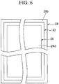
- An outline of the plate-shaped member 28 is configured to be larger than an outline of the cooling member 26 (see FIG. 6 ).
- a thickness of the plate-shaped member 28 is not particularly limited, for example, the thickness may be appropriately set within a range of 0.5 mm or more and 10 mm or less.
- the bonding sections 34 are installed between the first side plane 28a of the plate-shaped member 28 and the outer circumferential surface of the tubular sections 10B.
- the bonding sections 34 are provided on both left and right sides perpendicular to an axial direction in a state in which the refrigerant pipe 10 is disposed along the plate-shaped member 28.
- the bonding sections 34 are continuously formed substantially throughout the length of facing portions of the refrigerant pipe 10 (the tubular section 10B) and the plate-shaped member 28.
- the bonding section 34 is a member configured to join the plate-shaped member 28 to the tubular sections 10B.
- an alloy a brazing material having a lower melting point than the welding section formed when a welding method is used, or the plate-shaped member 28 and the tubular sections 10B, may be used as the bonding sections 34.
- the plate-shaped member 28 and the tubular sections 10B are preferably bonded using, for example, an alloy formed of a Cu alloy as the bonding sections 34.
- the cooling member 26 has a first block 26a, the second block 26b, the block attachment/detachment screw 31 and a pipe attachment/detachment screw 32.
- the first block 26a is formed diagonally with respect to the rear surface 21b of the circuit board 21 in the inclined direction of the plate-shaped member 28.
- the first block 26a has a plane 26c that is one plane of the cooling member 26, and a surface 26e disposed opposite to the plane 26c.
- the plane 26c is a plane in contact with the sheet-shaped heat transfer member 33.
- the surface 26e is a curved surface protruding from the plate-shaped member 28 toward the rear surface 21b of the circuit board 21.
- a protrusion 26g protruding in the widthwise direction of the housing 23 is formed on the surface 26e.
- the protrusion 26g is formed at a position close to an end portion of the surface 26e separated from the circuit board 21.
- the surface 26e may be, for example, a plane, or may be a stepped shape when seen from above.
- the second block 26b is installed on the first block 26a while coming in contact with the surface 26e.
- the second block 26b has a surface 26f in contact with the surface 26e, and a surface 26d disposed opposite to the surface 26f.
- the surface 26f is a curved surface recessed to correspond to the curved shape of the surface 26e. Accordingly, the surface 26f comes in surface contact with the surface 26e. In addition, in a state in which the surface 26f and the surface 26e come in surface contact with each other, in end portions of the second block 26b, an end portion of a side separated from the circuit board 21 abuts the protrusion 26g.
- the surface 26d is constituted by the two planes 26d1 and 26d2 that cross each other.
- the plane 26d1 faces the rear surface 21b of the circuit board 21.
- the plane 26d2 faces the housing 23 in the widthwise direction. Accordingly, the planes 26d1 and 26d2 are disposed in a direction along the circuit board 21 and a direction standing upward from the circuit board 21.
- the block attachment/detachment screw 31 is threadedly engaged with the second block 26b and the first block 26a such that a shaft section (not shown) reaches the first block 26a from the plane 26d1 side facing the attachment/detachment through-hole 27 formed in the circuit board 21.
- a head section 31a of the block attachment/detachment screw 31 faces the attachment/detachment through-hole 27 to be exposed from the plane 26d1.
- the head section 31a of the block attachment/detachment screw 31 is configured to be smaller than the attachment/detachment through-hole 27 such that the head section 31a can pass through the attachment/detachment through-hole 27. Accordingly, the block attachment/detachment screw 31 can be operated from the front surface 21a side of the circuit board 21.
- the cooling member 26 configured as described above cools the heat generating parts 25A and 25B using the cold of the refrigerant transmitted through the plate-shaped member 28.
- An opening section 14a is installed on the board accommodating section 14.
- the heat generating parts 25A and 25B mounted on the rear surface 21b of the circuit board 21 protrude toward the back side of the board accommodating section 14 via the opening section 14a.
- the heat generating parts 25A and 25B are fixed to the surfaces 26d (specifically, the planes 26d1 and 26d2) by attachment screws or the like (not shown), respectively.
- the sheet-shaped heat transfer member 33 is installed to be adhered to the second side plane 28b of the plate-shaped member 28 and the plane 26c of the cooling member 26 between the plate-shaped member 28 and the cooling member 26.
- the sheet-shaped heat transfer member 33 transmits the cold of the refrigerant flowing through the tubular sections 10B to the cooling member 26 while suppressing a direct contact between the plate-shaped member 28 and the cooling member 26 formed of dissimilar metals.
- the sheet-shaped heat transfer member 33 is adhered to the two planes (the plane 26c and the second side plane 28b), adhesiveness between the plate-shaped member 28, the cooling member 26 and the sheet-shaped heat transfer member 33 can be improved. Accordingly, interface corrosion due to the contact between the cooling member 26 and the refrigerant pipe 10 can be further suppressed.
- a heat conductive sheet such as a heat conductive viscous sheet, a heat conductive adhesive sheet, a heat conductive rubber, or the like, a heat conductive phase change sheet, and so on may be used as the sheet-shaped heat transfer member 33.
- the heat conductive silicone rubber may be used as the heat conductive rubber, or a rubber other than the heat conductive silicone rubber may be used as the heat conductive rubber.
- the heat conductive sheet or the heat conductive phase change sheet is preferably used as the sheet-shaped heat transfer member 33.
- the heat conductive phase change sheet is softened by heat, heat conductivity between the plate-shaped member 28 and the cooling member 26 can be increased.
- the sheet-shaped heat transfer member 33 is preferably formed such that a circumferential edge of the sheet-shaped heat transfer member 33 extends beyond the outline of the plane 26c of the cooling member 26.
- the sheet-shaped heat transfer member 33 is formed such that a circumferential edge of the sheet-shaped heat transfer member 33 extends beyond the outline of the plane 26c of the cooling member 26, direct contact between the cooling member 26 and the refrigerant pipe 10 can be minimized.
- the composite pipe 22 of the embodiment since direct contact between the cooling member 26 and the refrigerant pipe 10 can be minimized by interposing the plate-shaped member 28 and the sheet-shaped heat transfer member 33 between the cooling member 26 and the refrigerant pipe 10 that are formed of a different metal from the refrigerant pipe 10 (the tubular section 10B), interface corrosion that occurs due to the contact between the cooling member 26 and the refrigerant pipe 10 that are formed of dissimilar metals can be minimized.
- the sheet-shaped heat transfer member 33 is interposed between the plate-shaped member 28 and the cooling member 26 that are formed of the same metal as the refrigerant pipe 10, interface corrosion on the interface between the plate-shaped member 28 and the cooling member 26 can be minimized.
- the cooling member 26 and the sheet-shaped heat transfer member can be improved by attaching the two planes (the plane 26c and the second side plane 28b) to the sheet-shaped heat transfer member 33, interface corrosion due to the contact between the cooling member 26 and the refrigerant pipe 10 can be further minimized.
- the heat generating parts 25A and 25B can be sufficiently cooled while minimizing interface corrosion due to the contact between the cooling member 26 and the refrigerant pipe 10.
- FIGS. 7 and 8 a composite pipe 40 according to a variant of the embodiment will be described with reference to FIGS. 7 and 8 .
- FIG. 7 the same components as in the structure shown in FIG. 5 are designated by the same reference numerals.
- FIG. 8 the same components as in the structure shown in FIG. 7 are designated by the same reference numerals.
- the composite pipe 40 is configured similarly to the composite pipe 22 as described above except that the outline of the second side plane 28b of the plate-shaped member 28 is smaller than the outline of the plane 26c of the cooling member 26, and the sheet-shaped heat transfer member 33 is formed such that a circumferential edge of the sheet-shaped heat transfer member 33 extends beyond the outline of the second side plane 28b of the plate-shaped member 28.
- the composite pipe 40 having the above-mentioned configuration can obtain the same effect as the composite pipe 22 described as above.
- the area of the refrigerant pipe 10 disposed to come in contact with the cooling member 26 is not limited to the area 10A between the electronic expansion valve 6 and the indoor heat exchanger 8.
- the area of the refrigerant pipe 10 disposed to come in contact with the cooling member 26 may be, for example, another area of the refrigerant pipe 10 that can cool the heat generating parts 25A and 25B installed on the controller 12.
- the area may be an area between the electronic expansion valve 6 and the outdoor heat exchanger 5. That is, the composite pipe 22 can be applied to various areas in the refrigerating cycle 11.
- the configuration of the refrigerating apparatus 1 may be applied to another refrigerating apparatus including a refrigerating cycle.
Landscapes
- Engineering & Computer Science (AREA)
- Physics & Mathematics (AREA)
- Mechanical Engineering (AREA)
- General Engineering & Computer Science (AREA)
- Geometry (AREA)
- Thermal Sciences (AREA)
- Chemical & Material Sciences (AREA)
- Combustion & Propulsion (AREA)
- Cooling Or The Like Of Electrical Apparatus (AREA)
Abstract
Description
- The present invention relates to a composite pipe and a refrigerating apparatus.
- In a refrigerating apparatus, cooling of heat generating parts of a board unit by mounting a cooling jacket that supports a copper pipe through which a refrigerant is allowed to flow on the heat generating parts is known. In such a refrigerating apparatus, reduction of thermal resistance between the cooling jacket and a pipe is performed by interposing a heat transfer sheet between the cooling jacket and the pipe (for example, see Japanese Unexamined Patent Application, First Publication No.
2015-233074 -
JP Publication No. 2015-233074 - A metal that is a material of the cooling pipe may be a different kind of metal from a metal that is a material of the cooling jacket.
- However, in the refrigerating apparatus disclosed in
JP Publication No. 2015-233074 - In this way, if the adhesiveness of the heat transfer sheet to the cooling pipe and the curved section decreases, the cooling pipe and the cooling jacket may come in direct contact with each other.
- Then, when the material of the cooling pipe and the material of the cooling jacket are dissimilar metals, since ionization tendencies of these metals are different, interface corrosion due to bonding of the dissimilar metals may occur.
- Here, the present invention is directed to providing a composite pipe and a refrigerating apparatus that are capable of suppressing interface corrosion due to contact between dissimilar metals.
- In order to solve the problems, a composite pipe according to an aspect of the present invention includes: a refrigerant pipe formed of a metal and through which a refrigerant is allowed to flow; a plate-shaped member formed of the same metal of the refrigerant pipe and having a first side plane in contact with an outer circumferential surface of the refrigerant pipe and a second side plane opposite to the first side plane; a bonding section installed between the first side plane of the plate-shaped member and the outer circumferential surface of the refrigerant pipe so as to join the refrigerant pipe with the plate-shaped member; a cooling member configured to cool heat generating parts via the plate-shaped member by the refrigerant flowing through the refrigerant pipe, which is formed of a different metal from the refrigerant pipe and the plate-shaped member, and has a first surface facing the second side plane of the plate-shaped member and a second surface opposite to the first surface and in contact with the heat generating parts; and a sheet-shaped heat transfer member installed between the plate-shaped member and the cooling member so as to be adhered to the second side plane of the plate-shaped member and the first surface of the cooling member.
- According to the present invention, since the plate-shaped member and the sheet-shaped heat transfer member are interposed between the cooling member and the refrigerant pipe formed of the different metal from the refrigerant pipe, direct contact between the cooling member and the refrigerant pipe can be minimized. Accordingly, interface corrosion due to contact between the cooling member and the refrigerant pipe that are formed of dissimilar metals can be minimized.
- Also, since the sheet-shaped heat transfer member is interposed between the plate-shaped member and the cooling member that are formed of the same metal as the refrigerant pipe, direct contact between the plate-shaped member and the cooling member that are formed of dissimilar metals can be minimized. Accordingly, interface corrosion on an interface between the plate-shaped member and the cooling member can be minimized.
- In addition, since a surface of the plate-shaped member adhered to the sheet-shaped heat transfer member (the other plane) and a surface of the cooling member (the one plane) are planes, adhesiveness between the other plane of the plate-shaped member, the plane of the cooling member and the sheet-shaped heat transfer member can be improved. Accordingly, since direct contact between the cooling member and the refrigerant pipe can be further minimized, interface corrosion due to contact between the cooling member and the refrigerant pipe can be further minimized.
- In the composite pipe according to an aspect of the present invention, the sheet-shaped heat transfer member may be a heat conductive sheet or a heat conductive phase change sheet.
- The heat conductive sheet or the heat conductive phase change sheet can be used as the sheet-shaped heat transfer member. In particular, since the heat conductive phase change sheet is softened by heat, heat conductivity between the plate-shaped member and the cooling member can be increased.
- In addition, since the heat conductive sheet or the heat conductive phase change sheet is used, occurrence of thickness non-uniformity that occurs when a silicone grease is used can be minimized.
- In the composite pipe according to an aspect of the present invention, it may be such that an outline of one of the second side plane of the plate-shaped member and the first surface of the cooling member is smaller than that of the other, and the sheet-shaped heat transfer member is in contact with the one of the second side plane of the plate-shaped member and the first surface of the cooling member such that a circumferential edge of the sheet-shaped heat transfer member extends beyond the outline of the one.
- As the above-mentioned configuration is provided, direct contact between the cooling member and the refrigerant pipe can be further minimized.
- A refrigerating apparatus according to an aspect of the present invention may include: the above mentioned composite pipe; and a circuit board provided with a circuit board main body whose circuit pattern is formed on one surface of the circuit main body and the heat generating parts being mounted on the circuit pattern, wherein the heat generating parts are in contact with the second surface of the cooling member.
- According to the refrigerating apparatus configured as described above, the heat generating parts can be sufficiently cooled while minimizing interface corrosion due to contact between the cooling member and the refrigerant pipe.
- According to the present invention, interface corrosion due to contact between dissimilar metals can be minimized.
-
-
FIG. 1 is a view schematically showing a schematic configuration of a refrigerating apparatus according to an embodiment of the present invention. -
FIG. 2 is an exploded perspective view showing a board accommodating section on which a controller shown inFIG. 1 is installed, and a refrigerant pipe. -
FIG. 3 is a cross-sectional view of a structure in an A1-A2 line direction shown inFIG. 2 . -
FIG. 4 is an enlarged cross-sectional view of a major part of the structure in a state in which the structure shown inFIG. 3 is assembled. -
FIG. 5 is a cross-sectional view in which a circuit board, heat generating parts and a composite pipe, shown inFIG. 4 , are simplified. -
FIG. 6 is a view showing a plate-shaped member, a sheet-shaped heat transfer member and a cooling member shown inFIG. 5 from an arrow B. -
FIG. 7 is a cross-sectional view for explaining a composite pipe according to a variant of the embodiment. -
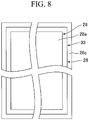
FIG. 8 is a view showing a plate-shaped member, a sheet-shaped heat transfer member and a cooling member shown inFIG. 7 from an arrow C. - Referring to
FIGS. 1 to 3 , a refrigerating apparatus 1 of an embodiment will be described. InFIG. 1 , an air conditioner is exemplarily shown as an example of the refrigerating apparatus 1. In the structures shown inFIGS. 1 to 3 , the same reference numerals designate the same components. - The refrigerating apparatus (the air conditioner) 1 has a refrigerating
cycle 11, acontroller 12, aboard accommodating section 14 and ahousing 23. - The refrigerating
cycle 11 has a compressor 2, a four-way switching valve 3, an outdoor fan 4, anoutdoor heat exchanger 5, an electronic expansion valve (EEV) 6, an indoor fan 7, anindoor heat exchanger 8, anaccumulator 9 and arefrigerant pipe 10. - The refrigerating
cycle 11 constitutes a closed cycle by connecting the compressor 2, the four-way switching valve 3, the outdoor fan 4, theoutdoor heat exchanger 5, theelectronic expansion valve 6, the indoor fan 7, theindoor heat exchanger 8 and theaccumulator 9 using therefrigerant pipe 10. - The compressor 2, the four-
way switching valve 3, the outdoor fan 4, theoutdoor heat exchanger 5, theelectronic expansion valve 6 and theaccumulator 9 are accommodated in thehousing 23 of outdoor equipment. The indoor fan 7 and theindoor heat exchanger 8 are accommodated in a housing (not shown) of indoor equipment. - The compressor 2 compresses a refrigerant flowing through the
refrigerant pipe 10. The four-way switching valve 3 switches a circulating direction of the refrigerant. - The outdoor heat exchanger 5 exchanges heat between the refrigerant flowing through the
refrigerant pipe 10 and external air from the outdoor fan 4. Theelectronic expansion valve 6 adiabatically expands the refrigerant flowing through therefrigerant pipe 10. - The
indoor heat exchanger 8 exchanges heat between the refrigerant flowing through therefrigerant pipe 10 and indoor air from the indoor fan 7. - The
accumulator 9 separates a liquid phase of the refrigerant that cannot be evaporated by an evaporator, and suppresses the liquid phase from flowing into the compressor 2. - The
board accommodating section 14 is accommodated in thehousing 23. Thecontroller 12 is attached to theboard accommodating section 14. - The
board accommodating section 14 is disposed in thehousing 23 of the outdoor equipment at an interval with an inner surface of a near side and an inner surface of a back side of thehousing 23. Here, "the near side" is referred to as a front surface side when the outdoor equipment is installed, and "the back side" is referred to as a rear surface side when the outdoor equipment is installed. - The
controller 12 controls an operation of the refrigerating apparatus 1 on the basis of an operation order from an operation unit such as a remote controller or the like. Thecontroller 12 is accommodated in thehousing 23 of the outdoor equipment. - For example, the
controller 12 switches the four-way switching valve 3 according to the operation mode and further controls rotational speeds of the outdoor fan 4 and the indoor fan 7, an opening angle of theelectronic expansion valve 6, and so on, while mounting an inverter configured to control a rotational speed of the compressor 2. - The
controller 12 has acircuit board 21 attached to theboard accommodating section 14, and various electronic parts includingheat generating parts - The
circuit board 21 has a plate-shaped circuit board main body formed of an insulating material, and circuit patterns formed on one surface and the other surface of the circuit board main body. - The
circuit board 21 has afront surface 21a (a surface of the circuit board main body disposed on the side of the other surface), and arear surface 21b (a surface of the circuit board main body disposed on the side of the one surface). - The
circuit board 21 may have an attachment/detachment through-hole 27 configured to attach and detach a block attachment/detachment screw 31 to/from a portion opposite to a block attachment/detachment screw 31, which will be described below. - Further, in the embodiment, the
front surface 21a of thecircuit board 21 is disposed toward the near side, and therear surface 21b of thecircuit board 21 is disposed toward the back side. - For example, an active converter, a diode module, a power transistor, and so on, which constitute an inverter, may be exemplified as the various electronic parts.
- Some of the various electronic parts are mounted in a circuit pattern (the
front surface 21a of the circuit board 21) formed on the other surface of the circuit board main body. - The
heat generating part 25A comes in contact with a plane 26d2 of asecond block 26b, which will be described below. Theheat generating part 25B comes in contact with a plane 26d1 of thesecond block 26b, which will be described below. - The
heat generating parts heat generating parts rear surface 21b of the circuit board 21) formed on the other surface of the circuit board main body. - Accordingly, the
heat generating parts circuit board 21. For example, power devices may be exemplified as theheat generating parts - Next, referring to
FIGS. 2 to 4 , therefrigerant pipe 10 will be described. InFIG. 4 , the same components as in the structures shown inFIGS. 2 and 3 are designated by the same reference numerals. - The
refrigerant pipe 10 has anarea 10A formed between theelectronic expansion valve 6 and theindoor heat exchanger 8. Thearea 10A is disposed at therear surface 21b side of thecircuit board 21 on the back side of theboard accommodating section 14 in thehousing 23. - In the
area 10A, a pair oftubular sections 10B are formed from therefrigerant pipe 10 formed in a U shape. Accordingly, therefrigerant pipe 10 has the pair oftubular sections 10B. - The pair of
tubular sections 10B are disposed parallel to an inclined direction with respect to a backward direction of the housing 23 (a direction from the near side toward the back side). More specifically, with respect to one of thetubular sections 10B, the other of thetubular sections 10B is disposed on the back side in thehousing 23, and disposed on a side of aside surface 24 that is an end surface of thehousing 23 in the widthwise direction. - The
refrigerant pipe 10 configured as described above is formed of a metal (a metal material) different from a metal (a metal material) of a cooling member 26 (to be described below). For example, a metal material having good heat conductivity may be used as the metal material of therefrigerant pipe 10. Specifically, for example, Cu, a Cu alloy, or the like may be used as the metal material of therefrigerant pipe 10. - The refrigerating apparatus (the air conditioner) 1 further has a
composite pipe 22. - Here, the
composite pipe 22 will be described with reference toFIGS. 2 to 6 . InFIG. 5 , the same components as in the structures shown inFIGS. 2 to 4 are designated by the same reference numerals. InFIG. 6 , the same components as in the structure shown inFIG. 5 are designated by the same reference numerals. - The
composite pipe 22 has thetubular sections 10B that are a part of therefrigerant pipe 10, a plate-shapedmember 28,bonding sections 34, the coolingmember 26 and a sheet-shapedheat transfer member 33. - The
tubular section 10B is sandwiched between an inclined surface of abracket 29 disposed below the plate-shapedmember 28, protruding from theboard accommodating section 14 toward the back face and substantially triangular when seen in a plan view and aclipping piece 30 facing the inclined surface at a predetermined position and in a predetermined direction. - The plate-shaped
member 28 is formed of the same metal of thetubular section 10B. The plate-shapedmember 28 has afirst side plane 28a in contact with an outer circumferential surface of thetubular section 10B (the refrigerant pipe 10), and asecond side plane 28b disposed opposite to thefirst side plane 28a. Thesecond side plane 28b is in contact with the sheet-shapedheat transfer member 33. - The plate-shaped
member 28 is inclined diagonally corresponding to thetubular sections 10B in a direction in which the pair oftubular sections 10B are arranged. - An outline of the plate-shaped
member 28 is configured to be larger than an outline of the cooling member 26 (seeFIG. 6 ). - In addition, while a thickness of the plate-shaped
member 28 is not particularly limited, for example, the thickness may be appropriately set within a range of 0.5 mm or more and 10 mm or less. - The
bonding sections 34 are installed between thefirst side plane 28a of the plate-shapedmember 28 and the outer circumferential surface of thetubular sections 10B. Thebonding sections 34 are provided on both left and right sides perpendicular to an axial direction in a state in which therefrigerant pipe 10 is disposed along the plate-shapedmember 28. In addition, thebonding sections 34 are continuously formed substantially throughout the length of facing portions of the refrigerant pipe 10 (thetubular section 10B) and the plate-shapedmember 28. - The
bonding section 34 is a member configured to join the plate-shapedmember 28 to thetubular sections 10B. For example, an alloy (a brazing material) having a lower melting point than the welding section formed when a welding method is used, or the plate-shapedmember 28 and thetubular sections 10B, may be used as thebonding sections 34. - Further, for example, when a Cu alloy is used as the metal material of the
refrigerant pipe 10 and the plate-shapedmember 28, the plate-shapedmember 28 and thetubular sections 10B are preferably bonded using, for example, an alloy formed of a Cu alloy as thebonding sections 34. - The cooling
member 26 has afirst block 26a, thesecond block 26b, the block attachment/detachment screw 31 and a pipe attachment/detachment screw 32. - The
first block 26a is formed diagonally with respect to therear surface 21b of thecircuit board 21 in the inclined direction of the plate-shapedmember 28. - The
first block 26a has aplane 26c that is one plane of the coolingmember 26, and asurface 26e disposed opposite to theplane 26c. - The
plane 26c is a plane in contact with the sheet-shapedheat transfer member 33. Thesurface 26e is a curved surface protruding from the plate-shapedmember 28 toward therear surface 21b of thecircuit board 21. - In addition, a
protrusion 26g protruding in the widthwise direction of thehousing 23 is formed on thesurface 26e. Theprotrusion 26g is formed at a position close to an end portion of thesurface 26e separated from thecircuit board 21. - Further, while the case in which the
surface 26e is the curved surface has been exemplarily described as an example inFIG. 4 , thesurface 26e may be, for example, a plane, or may be a stepped shape when seen from above. - The
second block 26b is installed on thefirst block 26a while coming in contact with thesurface 26e. Thesecond block 26b has asurface 26f in contact with thesurface 26e, and asurface 26d disposed opposite to thesurface 26f. - The
surface 26f is a curved surface recessed to correspond to the curved shape of thesurface 26e. Accordingly, thesurface 26f comes in surface contact with thesurface 26e. In addition, in a state in which thesurface 26f and thesurface 26e come in surface contact with each other, in end portions of thesecond block 26b, an end portion of a side separated from thecircuit board 21 abuts theprotrusion 26g. - The
surface 26d is constituted by the two planes 26d1 and 26d2 that cross each other. - The plane 26d1 faces the
rear surface 21b of thecircuit board 21. The plane 26d2 faces thehousing 23 in the widthwise direction. Accordingly, the planes 26d1 and 26d2 are disposed in a direction along thecircuit board 21 and a direction standing upward from thecircuit board 21. - The block attachment/
detachment screw 31 is threadedly engaged with thesecond block 26b and thefirst block 26a such that a shaft section (not shown) reaches thefirst block 26a from the plane 26d1 side facing the attachment/detachment through-hole 27 formed in thecircuit board 21. - A
head section 31a of the block attachment/detachment screw 31 faces the attachment/detachment through-hole 27 to be exposed from the plane 26d1. Thehead section 31a of the block attachment/detachment screw 31 is configured to be smaller than the attachment/detachment through-hole 27 such that thehead section 31a can pass through the attachment/detachment through-hole 27. Accordingly, the block attachment/detachment screw 31 can be operated from thefront surface 21a side of thecircuit board 21. - The cooling
member 26 configured as described above cools theheat generating parts member 28. - An
opening section 14a is installed on theboard accommodating section 14. Theheat generating parts rear surface 21b of thecircuit board 21 protrude toward the back side of theboard accommodating section 14 via theopening section 14a. Theheat generating parts surfaces 26d (specifically, the planes 26d1 and 26d2) by attachment screws or the like (not shown), respectively. - The sheet-shaped
heat transfer member 33 is installed to be adhered to thesecond side plane 28b of the plate-shapedmember 28 and theplane 26c of the coolingmember 26 between the plate-shapedmember 28 and the coolingmember 26. - The sheet-shaped
heat transfer member 33 transmits the cold of the refrigerant flowing through thetubular sections 10B to the coolingmember 26 while suppressing a direct contact between the plate-shapedmember 28 and the coolingmember 26 formed of dissimilar metals. - In this way, since direct contact between the cooling
member 26 and therefrigerant pipe 10 can be minimized by interposing the plate-shapedmember 28 and the sheet-shapedheat transfer member 33 between the coolingmember 26 and therefrigerant pipe 10 that are formed of a different metal from the refrigerant pipe 10 (thetubular section 10B), interface corrosion that occurs due to the contact between the coolingmember 26 and therefrigerant pipe 10 formed of the dissimilar metals can be minimized. - In addition, since the direct contact between the plate-shaped
member 28 and the coolingmember 26 formed of the dissimilar metals can be minimized by interposing the sheet-shapedheat transfer member 33 between the plate-shapedmember 28 and the coolingmember 26 formed of the same metal as therefrigerant pipe 10, interface corrosion on an interface between the plate-shapedmember 28 and the coolingmember 26 can be minimized. - In addition, since the sheet-shaped
heat transfer member 33 is adhered to the two planes (theplane 26c and thesecond side plane 28b), adhesiveness between the plate-shapedmember 28, the coolingmember 26 and the sheet-shapedheat transfer member 33 can be improved. Accordingly, interface corrosion due to the contact between the coolingmember 26 and therefrigerant pipe 10 can be further suppressed. - For example, a heat conductive sheet such as a heat conductive viscous sheet, a heat conductive adhesive sheet, a heat conductive rubber, or the like, a heat conductive phase change sheet, and so on may be used as the sheet-shaped
heat transfer member 33. For example, the heat conductive silicone rubber may be used as the heat conductive rubber, or a rubber other than the heat conductive silicone rubber may be used as the heat conductive rubber. - For example, the heat conductive sheet or the heat conductive phase change sheet is preferably used as the sheet-shaped
heat transfer member 33. In particular, since the heat conductive phase change sheet is softened by heat, heat conductivity between the plate-shapedmember 28 and the coolingmember 26 can be increased. - In addition, since the heat conductive sheet or the heat conductive phase change sheet is used, occurrence of thickness non-uniformity that occurs when a silicone grease is used can be minimized.
- As shown in
FIG. 6 , in a case where the outline of theplane 26c of the coolingmember 26 is smaller than the outline of thesecond side plane 28b of the plate-shapedmember 28, the sheet-shapedheat transfer member 33 is preferably formed such that a circumferential edge of the sheet-shapedheat transfer member 33 extends beyond the outline of theplane 26c of the coolingmember 26. - In this case, since the sheet-shaped
heat transfer member 33 is formed such that a circumferential edge of the sheet-shapedheat transfer member 33 extends beyond the outline of theplane 26c of the coolingmember 26, direct contact between the coolingmember 26 and therefrigerant pipe 10 can be minimized. - In addition, since the sheet-shaped
heat transfer member 33 is adhered to the planes (thesecond side plane 28b of the plate-shapedmember 28 and theplane 26c of the cooling member 26), an adhesive force between thesecond side plane 28b of the plate-shapedmember 28, theplane 26c of the coolingmember 26 and the sheet-shapedheat transfer member 33 can be sufficiently secured even when front surface roughness Ra of thesecond side plane 28b of the plate-shapedmember 28 and theplane 26c of the coolingmember 26 is high. - Accordingly, since high processing accuracy of front surfaces of the
second side plane 28b of the plate-shapedmember 28 and theplane 26c of the coolingmember 26 is not required when the front surfaces are processed, processing cost of thecomposite pipe 22 can be reduced. - According to the
composite pipe 22 of the embodiment, since direct contact between the coolingmember 26 and therefrigerant pipe 10 can be minimized by interposing the plate-shapedmember 28 and the sheet-shapedheat transfer member 33 between the coolingmember 26 and therefrigerant pipe 10 that are formed of a different metal from the refrigerant pipe 10 (thetubular section 10B), interface corrosion that occurs due to the contact between the coolingmember 26 and therefrigerant pipe 10 that are formed of dissimilar metals can be minimized. - In addition, since the sheet-shaped
heat transfer member 33 is interposed between the plate-shapedmember 28 and the coolingmember 26 that are formed of the same metal as therefrigerant pipe 10, interface corrosion on the interface between the plate-shapedmember 28 and the coolingmember 26 can be minimized. - In addition, since adhesiveness between the plate-shaped
member 28, the coolingmember 26 and the sheet-shaped heat transfer member can be improved by attaching the two planes (theplane 26c and thesecond side plane 28b) to the sheet-shapedheat transfer member 33, interface corrosion due to the contact between the coolingmember 26 and therefrigerant pipe 10 can be further minimized. - In addition, according to the refrigerating apparatus 1 including the
composite pipe 22, theheat generating parts member 26 and therefrigerant pipe 10. - Next, a
composite pipe 40 according to a variant of the embodiment will be described with reference toFIGS. 7 and8 . InFIG. 7 , the same components as in the structure shown inFIG. 5 are designated by the same reference numerals. InFIG. 8 , the same components as in the structure shown inFIG. 7 are designated by the same reference numerals. - The
composite pipe 40 is configured similarly to thecomposite pipe 22 as described above except that the outline of thesecond side plane 28b of the plate-shapedmember 28 is smaller than the outline of theplane 26c of the coolingmember 26, and the sheet-shapedheat transfer member 33 is formed such that a circumferential edge of the sheet-shapedheat transfer member 33 extends beyond the outline of thesecond side plane 28b of the plate-shapedmember 28. - The
composite pipe 40 having the above-mentioned configuration can obtain the same effect as thecomposite pipe 22 described as above. - While a preferred embodiment of the present invention has been described above in detail, the present invention is not limited to the specific embodiment and various modifications and changes may be made without departing from the spirit of the present invention disclosed in the scope of the following claims.
- For example, the area of the
refrigerant pipe 10 disposed to come in contact with the coolingmember 26 is not limited to thearea 10A between theelectronic expansion valve 6 and theindoor heat exchanger 8. - The area of the
refrigerant pipe 10 disposed to come in contact with the coolingmember 26 may be, for example, another area of therefrigerant pipe 10 that can cool theheat generating parts controller 12. Specifically, for example, the area may be an area between theelectronic expansion valve 6 and theoutdoor heat exchanger 5. That is, thecomposite pipe 22 can be applied to various areas in the refrigeratingcycle 11. - In addition, while the air conditioner has been exemplarily described as an example of the refrigerating apparatus 1 in the embodiment, the configuration of the refrigerating apparatus 1 may be applied to another refrigerating apparatus including a refrigerating cycle.
- While a preferred embodiment of the invention has been described and illustrated above, it should be understood that this is exemplary of the invention and is not to be considered as limiting. Additions, omissions, substitutions, and other modifications can be made without departing from the scope of the present invention. Accordingly, the invention is not to be considered as being limited by the foregoing description, and is only limited by the scope of the appended claims.
-
- 1 Refrigerating apparatus
- 2 Compressor
- 3 Four-way switching valve
- 4 Outdoor fan
- 5 Outdoor heat exchanger
- 6 Electronic expansion valve
- 7 Indoor fan
- 8 Indoor heat exchanger
- 9 Accumulator
- 10 Refrigerant pipe
- 21 Circuit board
- 22, 40 Composite pipe
- 25A, 25B Heat generating parts
- 26 Cooling member
- 28 Plate-shaped member
- 33 Sheet-shaped heat transfer member
- 34 Bonding section
Claims (4)
- A composite pipe (22;40) comprising:a refrigerant pipe (10) formed of a metal and through which a refrigerant is allowed to flow;a plate-shaped member (28) formed of the same metal of the refrigerant pipe (10) and having a first side plane (28a) in contact with an outer circumferential surface of the refrigerant pipe (10) and a second side plane (28b) opposite to the first side plane (28a);a bonding section (34) installed between the first side plane (28a) of the plate-shaped member (28) and the outer circumferential surface of the refrigerant pipe (10) so as to join the refrigerant pipe (10) with the plate-shaped member (28);a cooling member (26) configured to cool heat generating parts (25A,25B) via the plate-shaped member (28) by the refrigerant flowing through the refrigerant pipe (10), which is formed of a different metal from the refrigerant pipe (10) and the plate-shaped member (28), and has a first surface (26c) facing the second side plane (28b) of the plate-shaped member (28) and a second surface (26d) opposite to the first surface (26c) and in contact with the heat generating parts (25A,25B); anda sheet-shaped heat transfer member (33) installed between the plate-shaped member (28) and the cooling member (26) so as to be adhered to the second side plane (28b) of the plate-shaped member (28) and the first surface (26c) of the cooling member (26).
- The composite pipe (22;40) according to claim 1, wherein the sheet-shaped heat transfer member (33) is a heat conductive sheet or a heat conductive phase change sheet.
- The composite pipe (22;40) according to claim 1 or 2, wherein an outline of one of the second side plane (28b) of the plate-shaped member (28) and the first surface (26c) of the cooling member (26) is smaller than that of the other, and
the sheet-shaped heat transfer member (33) is in contact with the one of the second side plane (28b) of the plate-shaped member (28) and the first surface (26c) of the cooling member (26) such that a circumferential edge of the sheet-shaped heat transfer member (33) extends beyond the outline of the one. - A refrigerating apparatus (1) comprising:the composite pipe (22;40) according to any one of claims 1 to 3; anda circuit board (21) provided with a circuit board main body whose circuit pattern is formed on one surface of the circuit main body and the heat generating parts (25A,25B) being mounted on the circuit pattern, wherein the heat generating parts (25A,25B) are in contact with the second surface (26d) of the cooling member (26).
Applications Claiming Priority (1)
| Application Number | Priority Date | Filing Date | Title |
|---|---|---|---|
| JP2017129698A JP6963428B2 (en) | 2017-06-30 | 2017-06-30 | Refrigeration equipment |
Publications (2)
| Publication Number | Publication Date |
|---|---|
| EP3422402A1 true EP3422402A1 (en) | 2019-01-02 |
| EP3422402B1 EP3422402B1 (en) | 2021-01-27 |
Family
ID=62816441
Family Applications (1)
| Application Number | Title | Priority Date | Filing Date |
|---|---|---|---|
| EP18180529.2A Active EP3422402B1 (en) | 2017-06-30 | 2018-06-28 | Composite pipe and refrigerating apparatus |
Country Status (3)
| Country | Link |
|---|---|
| EP (1) | EP3422402B1 (en) |
| JP (1) | JP6963428B2 (en) |
| ES (1) | ES2862473T3 (en) |
Cited By (4)
| Publication number | Priority date | Publication date | Assignee | Title |
|---|---|---|---|---|
| US11846370B2 (en) | 2019-03-26 | 2023-12-19 | Titeflex Corporation | Multilayer composite pipe and pipe assemblies including reflective insulation |
| US12220894B2 (en) | 2020-07-31 | 2025-02-11 | Titeflex Corporation | Multilayer composite tube with flame-resistant layers |
| US12305792B2 (en) | 2019-03-26 | 2025-05-20 | Titeflex Corporation | Multilayer composite pipe and pipe assemblies including reflective insulation |
| US12320449B2 (en) | 2019-03-26 | 2025-06-03 | Titeflex Corporation | Multilayer composite pipe and pipe assemblies including reflective insulation |
Citations (5)
| Publication number | Priority date | Publication date | Assignee | Title |
|---|---|---|---|---|
| JP4973702B2 (en) * | 2009-02-02 | 2012-07-11 | ダイキン工業株式会社 | Electrical component module, cooling member coupling method, and air conditioner |
| CN202750393U (en) * | 2012-07-20 | 2013-02-20 | 深圳市飞荣达科技股份有限公司 | Heat conductive layer sheet |
| EP2848877A2 (en) * | 2013-09-16 | 2015-03-18 | Lg Electronics Inc. | Air conditioner |
| CN104650817A (en) * | 2015-02-12 | 2015-05-27 | 平湖阿莱德实业有限公司 | Heat conductive phase-change material and production method thereof |
| JP2015233074A (en) | 2014-06-10 | 2015-12-24 | ダイキン工業株式会社 | Parts cooling component |
Family Cites Families (11)
| Publication number | Priority date | Publication date | Assignee | Title |
|---|---|---|---|---|
| JP3183502B2 (en) * | 1997-09-11 | 2001-07-09 | 電気化学工業株式会社 | Heat radiation spacer |
| JP2005203735A (en) * | 2003-12-16 | 2005-07-28 | Fuji Polymer Industries Co Ltd | Thermally conductive composite sheet |
| JP4488093B2 (en) * | 2008-07-24 | 2010-06-23 | ダイキン工業株式会社 | Air conditioner |
| JP2010114121A (en) * | 2008-11-04 | 2010-05-20 | Daikin Ind Ltd | Heat radiator of electrical component |
| JP2011129644A (en) * | 2009-12-16 | 2011-06-30 | Tamagawa Engineering Kk | High frequency power source device |
| JP2011222579A (en) * | 2010-04-05 | 2011-11-04 | Kaneka Corp | Heat dissipation structure |
| JP2015002323A (en) * | 2013-06-18 | 2015-01-05 | 株式会社デンソー | Electronic device |
| JP2015218939A (en) * | 2014-05-16 | 2015-12-07 | パナソニックIpマネジメント株式会社 | Refrigeration cycle equipment |
| KR20160071708A (en) * | 2014-12-12 | 2016-06-22 | 엘지전자 주식회사 | An air conditioner |
| WO2016143070A1 (en) * | 2015-03-10 | 2016-09-15 | 三菱電機株式会社 | Power conversion device and refrigeration cycle device |
| JP2019011929A (en) * | 2017-06-30 | 2019-01-24 | 三菱重工サーマルシステムズ株式会社 | Composite tube, freezer, and manufacturing method of composite tube |
-
2017
- 2017-06-30 JP JP2017129698A patent/JP6963428B2/en active Active
-
2018
- 2018-06-28 ES ES18180529T patent/ES2862473T3/en active Active
- 2018-06-28 EP EP18180529.2A patent/EP3422402B1/en active Active
Patent Citations (5)
| Publication number | Priority date | Publication date | Assignee | Title |
|---|---|---|---|---|
| JP4973702B2 (en) * | 2009-02-02 | 2012-07-11 | ダイキン工業株式会社 | Electrical component module, cooling member coupling method, and air conditioner |
| CN202750393U (en) * | 2012-07-20 | 2013-02-20 | 深圳市飞荣达科技股份有限公司 | Heat conductive layer sheet |
| EP2848877A2 (en) * | 2013-09-16 | 2015-03-18 | Lg Electronics Inc. | Air conditioner |
| JP2015233074A (en) | 2014-06-10 | 2015-12-24 | ダイキン工業株式会社 | Parts cooling component |
| CN104650817A (en) * | 2015-02-12 | 2015-05-27 | 平湖阿莱德实业有限公司 | Heat conductive phase-change material and production method thereof |
Cited By (4)
| Publication number | Priority date | Publication date | Assignee | Title |
|---|---|---|---|---|
| US11846370B2 (en) | 2019-03-26 | 2023-12-19 | Titeflex Corporation | Multilayer composite pipe and pipe assemblies including reflective insulation |
| US12305792B2 (en) | 2019-03-26 | 2025-05-20 | Titeflex Corporation | Multilayer composite pipe and pipe assemblies including reflective insulation |
| US12320449B2 (en) | 2019-03-26 | 2025-06-03 | Titeflex Corporation | Multilayer composite pipe and pipe assemblies including reflective insulation |
| US12220894B2 (en) | 2020-07-31 | 2025-02-11 | Titeflex Corporation | Multilayer composite tube with flame-resistant layers |
Also Published As
| Publication number | Publication date |
|---|---|
| JP2019011930A (en) | 2019-01-24 |
| EP3422402B1 (en) | 2021-01-27 |
| JP6963428B2 (en) | 2021-11-10 |
| ES2862473T3 (en) | 2021-10-07 |
Similar Documents
| Publication | Publication Date | Title |
|---|---|---|
| EP3422402B1 (en) | Composite pipe and refrigerating apparatus | |
| EP3421905A1 (en) | Composite pipe, refrigerating apparatus, and method for manufacturing composite pipe | |
| US7813135B2 (en) | Semiconductor device | |
| US11557521B2 (en) | Heat sink and circuit device | |
| US9769955B2 (en) | Refrigerating apparatus | |
| CN104247011B (en) | Refrigerating plant | |
| US9949405B2 (en) | Electrical device | |
| US20190301753A1 (en) | Air-conditioning apparatus | |
| JP2010245174A (en) | Electronic control unit and manufacturing method thereof | |
| JP2010114121A (en) | Heat radiator of electrical component | |
| CN105723597A (en) | Electric compressor | |
| JP2013021348A (en) | Electronic control unit | |
| JP2019134669A (en) | Inverter | |
| JP2010145054A (en) | Refrigerating device | |
| US10356960B2 (en) | Device for radiating heat of capacitor of an inverter in an electric compressor | |
| CN105674643B (en) | refrigeration unit | |
| JP6410920B2 (en) | Power conversion device and refrigeration cycle device | |
| JP2006002755A5 (en) | ||
| JP2006002755A (en) | Inverter unit-integrated electric compressor and vehicle air conditioner using the same | |
| JP2018112371A (en) | Air conditioner | |
| JP6471417B2 (en) | Cooling jacket | |
| JP2013073949A (en) | Electric power conversion apparatus and freezer including the same | |
| JP7580654B2 (en) | Drive unit and air conditioning device | |
| CN220981611U (en) | Cold-hot side bonding assembled semiconductor refrigerating device | |
| JP7438434B1 (en) | Air conditioner circuit structure and air conditioner |
Legal Events
| Date | Code | Title | Description |
|---|---|---|---|
| PUAI | Public reference made under article 153(3) epc to a published international application that has entered the european phase |
Free format text: ORIGINAL CODE: 0009012 |
|
| STAA | Information on the status of an ep patent application or granted ep patent |
Free format text: STATUS: THE APPLICATION HAS BEEN PUBLISHED |
|
| AK | Designated contracting states |
Kind code of ref document: A1 Designated state(s): AL AT BE BG CH CY CZ DE DK EE ES FI FR GB GR HR HU IE IS IT LI LT LU LV MC MK MT NL NO PL PT RO RS SE SI SK SM TR |
|
| AX | Request for extension of the european patent |
Extension state: BA ME |
|
| STAA | Information on the status of an ep patent application or granted ep patent |
Free format text: STATUS: REQUEST FOR EXAMINATION WAS MADE |
|
| 17P | Request for examination filed |
Effective date: 20190701 |
|
| RBV | Designated contracting states (corrected) |
Designated state(s): AL AT BE BG CH CY CZ DE DK EE ES FI FR GB GR HR HU IE IS IT LI LT LU LV MC MK MT NL NO PL PT RO RS SE SI SK SM TR |
|
| STAA | Information on the status of an ep patent application or granted ep patent |
Free format text: STATUS: EXAMINATION IS IN PROGRESS |
|
| 17Q | First examination report despatched |
Effective date: 20190919 |
|
| GRAP | Despatch of communication of intention to grant a patent |
Free format text: ORIGINAL CODE: EPIDOSNIGR1 |
|
| STAA | Information on the status of an ep patent application or granted ep patent |
Free format text: STATUS: GRANT OF PATENT IS INTENDED |
|
| RIC1 | Information provided on ipc code assigned before grant |
Ipc: H01L 23/473 20060101ALI20200903BHEP Ipc: H01L 23/40 20060101AFI20200903BHEP Ipc: F28D 21/00 20060101ALI20200903BHEP Ipc: F25B 31/00 20060101ALI20200903BHEP Ipc: F28F 1/22 20060101ALI20200903BHEP Ipc: H05K 7/20 20060101ALI20200903BHEP Ipc: F24F 1/24 20110101ALI20200903BHEP |
|
| INTG | Intention to grant announced |
Effective date: 20200929 |
|
| GRAS | Grant fee paid |
Free format text: ORIGINAL CODE: EPIDOSNIGR3 |
|
| GRAA | (expected) grant |
Free format text: ORIGINAL CODE: 0009210 |
|
| STAA | Information on the status of an ep patent application or granted ep patent |
Free format text: STATUS: THE PATENT HAS BEEN GRANTED |
|
| AK | Designated contracting states |
Kind code of ref document: B1 Designated state(s): AL AT BE BG CH CY CZ DE DK EE ES FI FR GB GR HR HU IE IS IT LI LT LU LV MC MK MT NL NO PL PT RO RS SE SI SK SM TR |
|
| REG | Reference to a national code |
Ref country code: GB Ref legal event code: FG4D |
|
| REG | Reference to a national code |
Ref country code: CH Ref legal event code: EP |
|
| REG | Reference to a national code |
Ref country code: AT Ref legal event code: REF Ref document number: 1359128 Country of ref document: AT Kind code of ref document: T Effective date: 20210215 |
|
| REG | Reference to a national code |
Ref country code: IE Ref legal event code: FG4D |
|
| REG | Reference to a national code |
Ref country code: DE Ref legal event code: R096 Ref document number: 602018012195 Country of ref document: DE |
|
| REG | Reference to a national code |
Ref country code: NL Ref legal event code: MP Effective date: 20210127 |
|
| REG | Reference to a national code |
Ref country code: LT Ref legal event code: MG9D |
|
| REG | Reference to a national code |
Ref country code: AT Ref legal event code: MK05 Ref document number: 1359128 Country of ref document: AT Kind code of ref document: T Effective date: 20210127 |
|
| PG25 | Lapsed in a contracting state [announced via postgrant information from national office to epo] |
Ref country code: LT Free format text: LAPSE BECAUSE OF FAILURE TO SUBMIT A TRANSLATION OF THE DESCRIPTION OR TO PAY THE FEE WITHIN THE PRESCRIBED TIME-LIMIT Effective date: 20210127 Ref country code: PT Free format text: LAPSE BECAUSE OF FAILURE TO SUBMIT A TRANSLATION OF THE DESCRIPTION OR TO PAY THE FEE WITHIN THE PRESCRIBED TIME-LIMIT Effective date: 20210527 Ref country code: NO Free format text: LAPSE BECAUSE OF FAILURE TO SUBMIT A TRANSLATION OF THE DESCRIPTION OR TO PAY THE FEE WITHIN THE PRESCRIBED TIME-LIMIT Effective date: 20210427 Ref country code: FI Free format text: LAPSE BECAUSE OF FAILURE TO SUBMIT A TRANSLATION OF THE DESCRIPTION OR TO PAY THE FEE WITHIN THE PRESCRIBED TIME-LIMIT Effective date: 20210127 Ref country code: HR Free format text: LAPSE BECAUSE OF FAILURE TO SUBMIT A TRANSLATION OF THE DESCRIPTION OR TO PAY THE FEE WITHIN THE PRESCRIBED TIME-LIMIT Effective date: 20210127 Ref country code: GR Free format text: LAPSE BECAUSE OF FAILURE TO SUBMIT A TRANSLATION OF THE DESCRIPTION OR TO PAY THE FEE WITHIN THE PRESCRIBED TIME-LIMIT Effective date: 20210428 Ref country code: BG Free format text: LAPSE BECAUSE OF FAILURE TO SUBMIT A TRANSLATION OF THE DESCRIPTION OR TO PAY THE FEE WITHIN THE PRESCRIBED TIME-LIMIT Effective date: 20210427 |
|
| PG25 | Lapsed in a contracting state [announced via postgrant information from national office to epo] |
Ref country code: SE Free format text: LAPSE BECAUSE OF FAILURE TO SUBMIT A TRANSLATION OF THE DESCRIPTION OR TO PAY THE FEE WITHIN THE PRESCRIBED TIME-LIMIT Effective date: 20210127 Ref country code: AT Free format text: LAPSE BECAUSE OF FAILURE TO SUBMIT A TRANSLATION OF THE DESCRIPTION OR TO PAY THE FEE WITHIN THE PRESCRIBED TIME-LIMIT Effective date: 20210127 Ref country code: LV Free format text: LAPSE BECAUSE OF FAILURE TO SUBMIT A TRANSLATION OF THE DESCRIPTION OR TO PAY THE FEE WITHIN THE PRESCRIBED TIME-LIMIT Effective date: 20210127 Ref country code: RS Free format text: LAPSE BECAUSE OF FAILURE TO SUBMIT A TRANSLATION OF THE DESCRIPTION OR TO PAY THE FEE WITHIN THE PRESCRIBED TIME-LIMIT Effective date: 20210127 Ref country code: PL Free format text: LAPSE BECAUSE OF FAILURE TO SUBMIT A TRANSLATION OF THE DESCRIPTION OR TO PAY THE FEE WITHIN THE PRESCRIBED TIME-LIMIT Effective date: 20210127 |
|
| PG25 | Lapsed in a contracting state [announced via postgrant information from national office to epo] |
Ref country code: IS Free format text: LAPSE BECAUSE OF FAILURE TO SUBMIT A TRANSLATION OF THE DESCRIPTION OR TO PAY THE FEE WITHIN THE PRESCRIBED TIME-LIMIT Effective date: 20210527 |
|
| REG | Reference to a national code |
Ref country code: ES Ref legal event code: FG2A Ref document number: 2862473 Country of ref document: ES Kind code of ref document: T3 Effective date: 20211007 |
|
| REG | Reference to a national code |
Ref country code: DE Ref legal event code: R097 Ref document number: 602018012195 Country of ref document: DE |
|
| PG25 | Lapsed in a contracting state [announced via postgrant information from national office to epo] |
Ref country code: SM Free format text: LAPSE BECAUSE OF FAILURE TO SUBMIT A TRANSLATION OF THE DESCRIPTION OR TO PAY THE FEE WITHIN THE PRESCRIBED TIME-LIMIT Effective date: 20210127 Ref country code: EE Free format text: LAPSE BECAUSE OF FAILURE TO SUBMIT A TRANSLATION OF THE DESCRIPTION OR TO PAY THE FEE WITHIN THE PRESCRIBED TIME-LIMIT Effective date: 20210127 Ref country code: CZ Free format text: LAPSE BECAUSE OF FAILURE TO SUBMIT A TRANSLATION OF THE DESCRIPTION OR TO PAY THE FEE WITHIN THE PRESCRIBED TIME-LIMIT Effective date: 20210127 |
|
| PG25 | Lapsed in a contracting state [announced via postgrant information from national office to epo] |
Ref country code: RO Free format text: LAPSE BECAUSE OF FAILURE TO SUBMIT A TRANSLATION OF THE DESCRIPTION OR TO PAY THE FEE WITHIN THE PRESCRIBED TIME-LIMIT Effective date: 20210127 Ref country code: SK Free format text: LAPSE BECAUSE OF FAILURE TO SUBMIT A TRANSLATION OF THE DESCRIPTION OR TO PAY THE FEE WITHIN THE PRESCRIBED TIME-LIMIT Effective date: 20210127 Ref country code: DK Free format text: LAPSE BECAUSE OF FAILURE TO SUBMIT A TRANSLATION OF THE DESCRIPTION OR TO PAY THE FEE WITHIN THE PRESCRIBED TIME-LIMIT Effective date: 20210127 |
|
| PLBE | No opposition filed within time limit |
Free format text: ORIGINAL CODE: 0009261 |
|
| STAA | Information on the status of an ep patent application or granted ep patent |
Free format text: STATUS: NO OPPOSITION FILED WITHIN TIME LIMIT |
|
| 26N | No opposition filed |
Effective date: 20211028 |
|
| PG25 | Lapsed in a contracting state [announced via postgrant information from national office to epo] |
Ref country code: AL Free format text: LAPSE BECAUSE OF FAILURE TO SUBMIT A TRANSLATION OF THE DESCRIPTION OR TO PAY THE FEE WITHIN THE PRESCRIBED TIME-LIMIT Effective date: 20210127 Ref country code: MC Free format text: LAPSE BECAUSE OF FAILURE TO SUBMIT A TRANSLATION OF THE DESCRIPTION OR TO PAY THE FEE WITHIN THE PRESCRIBED TIME-LIMIT Effective date: 20210127 |
|
| REG | Reference to a national code |
Ref country code: CH Ref legal event code: PL |
|
| PG25 | Lapsed in a contracting state [announced via postgrant information from national office to epo] |
Ref country code: SI Free format text: LAPSE BECAUSE OF FAILURE TO SUBMIT A TRANSLATION OF THE DESCRIPTION OR TO PAY THE FEE WITHIN THE PRESCRIBED TIME-LIMIT Effective date: 20210127 |
|
| REG | Reference to a national code |
Ref country code: BE Ref legal event code: MM Effective date: 20210630 |
|
| PG25 | Lapsed in a contracting state [announced via postgrant information from national office to epo] |
Ref country code: LU Free format text: LAPSE BECAUSE OF NON-PAYMENT OF DUE FEES Effective date: 20210628 |
|
| PG25 | Lapsed in a contracting state [announced via postgrant information from national office to epo] |
Ref country code: LI Free format text: LAPSE BECAUSE OF NON-PAYMENT OF DUE FEES Effective date: 20210630 Ref country code: IT Free format text: LAPSE BECAUSE OF FAILURE TO SUBMIT A TRANSLATION OF THE DESCRIPTION OR TO PAY THE FEE WITHIN THE PRESCRIBED TIME-LIMIT Effective date: 20210127 Ref country code: IE Free format text: LAPSE BECAUSE OF NON-PAYMENT OF DUE FEES Effective date: 20210628 Ref country code: CH Free format text: LAPSE BECAUSE OF NON-PAYMENT OF DUE FEES Effective date: 20210630 |
|
| PG25 | Lapsed in a contracting state [announced via postgrant information from national office to epo] |
Ref country code: IS Free format text: LAPSE BECAUSE OF FAILURE TO SUBMIT A TRANSLATION OF THE DESCRIPTION OR TO PAY THE FEE WITHIN THE PRESCRIBED TIME-LIMIT Effective date: 20210527 |
|
| PG25 | Lapsed in a contracting state [announced via postgrant information from national office to epo] |
Ref country code: BE Free format text: LAPSE BECAUSE OF NON-PAYMENT OF DUE FEES Effective date: 20210630 |
|
| REG | Reference to a national code |
Ref country code: DE Ref legal event code: R082 Ref document number: 602018012195 Country of ref document: DE Representative=s name: CBDL PATENTANWAELTE GBR, DE Ref country code: DE Ref legal event code: R082 Ref document number: 602018012195 Country of ref document: DE Representative=s name: CBDL PATENTANWAELTE EGBR, DE |
|
| PG25 | Lapsed in a contracting state [announced via postgrant information from national office to epo] |
Ref country code: NL Free format text: LAPSE BECAUSE OF NON-PAYMENT OF DUE FEES Effective date: 20210127 Ref country code: CY Free format text: LAPSE BECAUSE OF FAILURE TO SUBMIT A TRANSLATION OF THE DESCRIPTION OR TO PAY THE FEE WITHIN THE PRESCRIBED TIME-LIMIT Effective date: 20210127 |
|
| PG25 | Lapsed in a contracting state [announced via postgrant information from national office to epo] |
Ref country code: HU Free format text: LAPSE BECAUSE OF FAILURE TO SUBMIT A TRANSLATION OF THE DESCRIPTION OR TO PAY THE FEE WITHIN THE PRESCRIBED TIME-LIMIT; INVALID AB INITIO Effective date: 20180628 |
|
| PG25 | Lapsed in a contracting state [announced via postgrant information from national office to epo] |
Ref country code: MK Free format text: LAPSE BECAUSE OF FAILURE TO SUBMIT A TRANSLATION OF THE DESCRIPTION OR TO PAY THE FEE WITHIN THE PRESCRIBED TIME-LIMIT Effective date: 20210127 |
|
| PG25 | Lapsed in a contracting state [announced via postgrant information from national office to epo] |
Ref country code: MT Free format text: LAPSE BECAUSE OF FAILURE TO SUBMIT A TRANSLATION OF THE DESCRIPTION OR TO PAY THE FEE WITHIN THE PRESCRIBED TIME-LIMIT Effective date: 20210127 |
|
| PGFP | Annual fee paid to national office [announced via postgrant information from national office to epo] |
Ref country code: DE Payment date: 20250507 Year of fee payment: 8 |
|
| PGFP | Annual fee paid to national office [announced via postgrant information from national office to epo] |
Ref country code: GB Payment date: 20250508 Year of fee payment: 8 |
|
| PGFP | Annual fee paid to national office [announced via postgrant information from national office to epo] |
Ref country code: FR Payment date: 20250508 Year of fee payment: 8 |
|
| PGFP | Annual fee paid to national office [announced via postgrant information from national office to epo] |
Ref country code: ES Payment date: 20250701 Year of fee payment: 8 |
|
| REG | Reference to a national code |
Ref country code: DE Ref legal event code: R079 Ref document number: 602018012195 Country of ref document: DE Free format text: PREVIOUS MAIN CLASS: H01L0023400000 Ipc: H10W0040600000 |
|
| PG25 | Lapsed in a contracting state [announced via postgrant information from national office to epo] |
Ref country code: TR Free format text: LAPSE BECAUSE OF FAILURE TO SUBMIT A TRANSLATION OF THE DESCRIPTION OR TO PAY THE FEE WITHIN THE PRESCRIBED TIME-LIMIT Effective date: 20210127 |