EP3422189B1 - Ereignisbasierte datenerfassung für intelligente sensoren auf einem master-slave-bus - Google Patents
Ereignisbasierte datenerfassung für intelligente sensoren auf einem master-slave-bus Download PDFInfo
- Publication number
- EP3422189B1 EP3422189B1 EP18177928.1A EP18177928A EP3422189B1 EP 3422189 B1 EP3422189 B1 EP 3422189B1 EP 18177928 A EP18177928 A EP 18177928A EP 3422189 B1 EP3422189 B1 EP 3422189B1
- Authority
- EP
- European Patent Office
- Prior art keywords
- event
- slave
- data
- sensing nodes
- master
- Prior art date
- Legal status (The legal status is an assumption and is not a legal conclusion. Google has not performed a legal analysis and makes no representation as to the accuracy of the status listed.)
- Active
Links
Images


Classifications
-
- G—PHYSICS
- G08—SIGNALLING
- G08B—SIGNALLING OR CALLING SYSTEMS; ORDER TELEGRAPHS; ALARM SYSTEMS
- G08B21/00—Alarms responsive to a single specified undesired or abnormal condition and not otherwise provided for
- G08B21/18—Status alarms
- G08B21/182—Level alarms, e.g. alarms responsive to variables exceeding a threshold
-
- H—ELECTRICITY
- H04—ELECTRIC COMMUNICATION TECHNIQUE
- H04L—TRANSMISSION OF DIGITAL INFORMATION, e.g. TELEGRAPHIC COMMUNICATION
- H04L12/00—Data switching networks
- H04L12/28—Data switching networks characterised by path configuration, e.g. LAN [Local Area Networks] or WAN [Wide Area Networks]
- H04L12/40—Bus networks
- H04L12/403—Bus networks with centralised control, e.g. polling
-
- G—PHYSICS
- G05—CONTROLLING; REGULATING
- G05B—CONTROL OR REGULATING SYSTEMS IN GENERAL; FUNCTIONAL ELEMENTS OF SUCH SYSTEMS; MONITORING OR TESTING ARRANGEMENTS FOR SUCH SYSTEMS OR ELEMENTS
- G05B19/00—Programme-control systems
- G05B19/02—Programme-control systems electric
- G05B19/04—Programme control other than numerical control, i.e. in sequence controllers or logic controllers
- G05B19/042—Programme control other than numerical control, i.e. in sequence controllers or logic controllers using digital processors
-
- G—PHYSICS
- G06—COMPUTING OR CALCULATING; COUNTING
- G06F—ELECTRIC DIGITAL DATA PROCESSING
- G06F11/00—Error detection; Error correction; Monitoring
- G06F11/30—Monitoring
- G06F11/3003—Monitoring arrangements specially adapted to the computing system or computing system component being monitored
- G06F11/3006—Monitoring arrangements specially adapted to the computing system or computing system component being monitored where the computing system is distributed, e.g. networked systems, clusters, multiprocessor systems
-
- G—PHYSICS
- G06—COMPUTING OR CALCULATING; COUNTING
- G06F—ELECTRIC DIGITAL DATA PROCESSING
- G06F11/00—Error detection; Error correction; Monitoring
- G06F11/30—Monitoring
- G06F11/3003—Monitoring arrangements specially adapted to the computing system or computing system component being monitored
- G06F11/3013—Monitoring arrangements specially adapted to the computing system or computing system component being monitored where the computing system is an embedded system, i.e. a combination of hardware and software dedicated to perform a certain function in mobile devices, printers, automotive or aircraft systems
-
- G—PHYSICS
- G06—COMPUTING OR CALCULATING; COUNTING
- G06F—ELECTRIC DIGITAL DATA PROCESSING
- G06F11/00—Error detection; Error correction; Monitoring
- G06F11/30—Monitoring
- G06F11/3003—Monitoring arrangements specially adapted to the computing system or computing system component being monitored
- G06F11/3027—Monitoring arrangements specially adapted to the computing system or computing system component being monitored where the computing system component is a bus
-
- G—PHYSICS
- G06—COMPUTING OR CALCULATING; COUNTING
- G06F—ELECTRIC DIGITAL DATA PROCESSING
- G06F11/00—Error detection; Error correction; Monitoring
- G06F11/30—Monitoring
- G06F11/3058—Monitoring arrangements for monitoring environmental properties or parameters of the computing system or of the computing system component, e.g. monitoring of power, currents, temperature, humidity, position, vibrations
-
- G—PHYSICS
- G06—COMPUTING OR CALCULATING; COUNTING
- G06F—ELECTRIC DIGITAL DATA PROCESSING
- G06F11/00—Error detection; Error correction; Monitoring
- G06F11/30—Monitoring
- G06F11/3065—Monitoring arrangements determined by the means or processing involved in reporting the monitored data
- G06F11/3072—Monitoring arrangements determined by the means or processing involved in reporting the monitored data where the reporting involves data filtering, e.g. pattern matching, time or event triggered, adaptive or policy-based reporting
-
- G—PHYSICS
- G06—COMPUTING OR CALCULATING; COUNTING
- G06F—ELECTRIC DIGITAL DATA PROCESSING
- G06F11/00—Error detection; Error correction; Monitoring
- G06F11/30—Monitoring
- G06F11/3089—Monitoring arrangements determined by the means or processing involved in sensing the monitored data, e.g. interfaces, connectors, sensors, probes, agents
-
- G—PHYSICS
- G07—CHECKING-DEVICES
- G07C—TIME OR ATTENDANCE REGISTERS; REGISTERING OR INDICATING THE WORKING OF MACHINES; GENERATING RANDOM NUMBERS; VOTING OR LOTTERY APPARATUS; ARRANGEMENTS, SYSTEMS OR APPARATUS FOR CHECKING NOT PROVIDED FOR ELSEWHERE
- G07C3/00—Registering or indicating the condition or the working of machines or other apparatus, other than vehicles
- G07C3/08—Registering or indicating the production of the machine either with or without registering working or idle time
- G07C3/10—Registering or indicating the production of the machine either with or without registering working or idle time using counting means
-
- G—PHYSICS
- G08—SIGNALLING
- G08B—SIGNALLING OR CALLING SYSTEMS; ORDER TELEGRAPHS; ALARM SYSTEMS
- G08B25/00—Alarm systems in which the location of the alarm condition is signalled to a central station, e.g. fire or police telegraphic systems
- G08B25/01—Alarm systems in which the location of the alarm condition is signalled to a central station, e.g. fire or police telegraphic systems characterised by the transmission medium
- G08B25/04—Alarm systems in which the location of the alarm condition is signalled to a central station, e.g. fire or police telegraphic systems characterised by the transmission medium using a single signalling line, e.g. in a closed loop
-
- G—PHYSICS
- G08—SIGNALLING
- G08B—SIGNALLING OR CALLING SYSTEMS; ORDER TELEGRAPHS; ALARM SYSTEMS
- G08B29/00—Checking or monitoring of signalling or alarm systems; Prevention or correction of operating errors, e.g. preventing unauthorised operation
- G08B29/02—Monitoring continuously signalling or alarm systems
- G08B29/04—Monitoring of the detection circuits
-
- G—PHYSICS
- G08—SIGNALLING
- G08B—SIGNALLING OR CALLING SYSTEMS; ORDER TELEGRAPHS; ALARM SYSTEMS
- G08B29/00—Checking or monitoring of signalling or alarm systems; Prevention or correction of operating errors, e.g. preventing unauthorised operation
- G08B29/18—Prevention or correction of operating errors
- G08B29/185—Signal analysis techniques for reducing or preventing false alarms or for enhancing the reliability of the system
- G08B29/188—Data fusion; cooperative systems, e.g. voting among different detectors
-
- G—PHYSICS
- G05—CONTROLLING; REGULATING
- G05B—CONTROL OR REGULATING SYSTEMS IN GENERAL; FUNCTIONAL ELEMENTS OF SUCH SYSTEMS; MONITORING OR TESTING ARRANGEMENTS FOR SUCH SYSTEMS OR ELEMENTS
- G05B2219/00—Program-control systems
- G05B2219/20—Pc systems
- G05B2219/22—Pc multi processor system
- G05B2219/2231—Master slave
-
- G—PHYSICS
- G06—COMPUTING OR CALCULATING; COUNTING
- G06F—ELECTRIC DIGITAL DATA PROCESSING
- G06F11/00—Error detection; Error correction; Monitoring
- G06F11/07—Responding to the occurrence of a fault, e.g. fault tolerance
- G06F11/0703—Error or fault processing not based on redundancy, i.e. by taking additional measures to deal with the error or fault not making use of redundancy in operation, in hardware, or in data representation
- G06F11/079—Root cause analysis, i.e. error or fault diagnosis
-
- G—PHYSICS
- G06—COMPUTING OR CALCULATING; COUNTING
- G06F—ELECTRIC DIGITAL DATA PROCESSING
- G06F11/00—Error detection; Error correction; Monitoring
- G06F11/30—Monitoring
- G06F11/34—Recording or statistical evaluation of computer activity, e.g. of down time, of input/output operation ; Recording or statistical evaluation of user activity, e.g. usability assessment
- G06F11/3466—Performance evaluation by tracing or monitoring
- G06F11/3476—Data logging
-
- G—PHYSICS
- G06—COMPUTING OR CALCULATING; COUNTING
- G06F—ELECTRIC DIGITAL DATA PROCESSING
- G06F2201/00—Indexing scheme relating to error detection, to error correction, and to monitoring
- G06F2201/81—Threshold
-
- G—PHYSICS
- G06—COMPUTING OR CALCULATING; COUNTING
- G06F—ELECTRIC DIGITAL DATA PROCESSING
- G06F2201/00—Indexing scheme relating to error detection, to error correction, and to monitoring
- G06F2201/86—Event-based monitoring
-
- G—PHYSICS
- G07—CHECKING-DEVICES
- G07C—TIME OR ATTENDANCE REGISTERS; REGISTERING OR INDICATING THE WORKING OF MACHINES; GENERATING RANDOM NUMBERS; VOTING OR LOTTERY APPARATUS; ARRANGEMENTS, SYSTEMS OR APPARATUS FOR CHECKING NOT PROVIDED FOR ELSEWHERE
- G07C3/00—Registering or indicating the condition or the working of machines or other apparatus, other than vehicles
Definitions
- the present disclosure relates generally to data collection, and in particular to data collection based upon event detection for smart sensors on a master/slave bus.
- Condition monitoring systems are often used to monitor parameters in machinery. These systems include temperature sensors, pressure sensors, vibration sensors, and many other types of sensors, utilized to detect the development of faults.
- the data collected may be digitized, transformed and algorithmically processed to extract features of the monitored system. A given feature can be generated from the input of one sensor or could be dependent on the interaction of multiple sensors. Features extracted may be compared against expected values to assess the relative health of that feature.
- Sensor data may be monitored and evaluated on a scheduled basis and/or on an event basis. Event based monitoring is typically used to diagnose the circumstances leading to the event, identify the event, and diagnose the potential impacts of the event. Because of this, it is desirable to have data from all relevant sensors collected prior to, during, and after the event detection. This is typically accomplished by buffering data from sensors of interest, retaining the buffered data when an event is detected, and recording the additional post-event data.
- Prior art condition monitoring systems included several analog sensors feeding into a central host for digitization and further processing. This implementation required individual cabling for each analog sensor which resulted in a heavy system that required a complicated installation. These issues can be mitigated by distributing digitization and processing of data out locally to the sensor. Local processing of data reduces the processing load on the host, allowing the host to perform other more complex functions, or decrease in size and complexity. Transmission of digital data allows multiple digital sensors to be connected on a single digital bus, reducing the wire weight associated with individual analog wire runs for each sensor.
- US2015/151960 discloses a sensor probe comprising one or more sensors in communication with a communication bus.
- US2007/174022 discloses a method and monitoring system for tracking operational parameters of a drive train comprising sensor units.
- WO2016/027022 discloses a motor vehicle computer comprising an integrated monitoring module comprising an acquisition unit, a triggering unit, and an extraction and backup unit.
- US5195046 discloses a system for monitoring a structure and detecting disturbances and faults comprising an actuation device for exciting the structure, a sensing device for transducing vibrations, and digital processing means for processing signals from the sensing device.
- a method of collecting data in a system that includes a master node and a plurality of slave sensing nodes connected via a master/slave data bus as claimed in claim 1.
- a system that includes a master/slave data bus, a plurality of sensing nodes, and a master node configured to communicate with the plurality of sensing nodes over the master/slave data bus as claimed in claim 9.
- a data collection system and method that performs event detection for nodes on a master/slave data bus.
- the system includes a host that acts as a master node for the master/slave data bus, and a plurality of slave sensing nodes, which may be digital sensors, for example.
- the master node commands the slave sensing nodes into an event monitoring mode, in which the slave sensing nodes enter a listening mode to continually digitize and retain an amount of data.
- the respective sensing node drives the master/slave bus with an "event trigger.”
- one or more of the remaining slave sensing nodes exit the listening mode and record an additional amount of event data.
- FIG. 1 is a block diagram illustrating system 10 that includes nodes 12a-12n connected on master/slave bus 14.
- System 10 includes sensing nodes 12a-12n, master/slave bus 14, host 16 and external systems 18.
- Each sensing node 12a-12n includes controller 20, timer/clock 22, memory 24 and sensing element 26.
- Master/Slave bus 14 includes bus termination 28.
- Host 16 includes controller 30, timer/clock 32 and memory 34.
- sensing nodes 12a-12n may act as slave nodes on master/slave bus 14 with host 16 acting as the master node.
- Sensing nodes 12a-12n may be any nodes capable of sensing characteristics of the environment and may be digital sensors, for example, or digital interfaces for analog sensors.
- nodes 12a-12n may be configured to sense temperature, vibration, speed, displacement, or any other characteristic.
- system 10 may be a health and usage monitoring system (HUMS) onboard an aircraft. In other embodiments, system 10 may be any ground-based or airborne system configured to monitor characteristics of the environment.
- HUMS health and usage monitoring system
- Sensing nodes 12a-12n are connected to communicate with host 16 over master/slave bus 14.
- Master/slave bus 14 may implement any master/slave communication protocol in which slave nodes respond to communication from a master node.
- it may be desirable to perform event based monitoring to diagnose the circumstances leading to an event, to identify the event, and to diagnose the potential impacts of the event.
- Host 16 may instruct one or more sensing nodes 12a-12n to enter an "event monitoring" mode.
- An event may be defined as any occurrence of one or more sensed values, and may be a single occurrence or a repeated occurrence.
- an event may be defined as a vibration or temperature exceeding a threshold.
- the event may be defined by the respective sensing node 12a-12n itself, or may be provided to the respective sensing node 12a-12n from host 16 at the beginning of the event monitoring mode.
- each respective sensing node 12a-12n may enter a listening mode.
- each respective sensing node 12a-12n may continually digitize and retain an amount of past data.
- the rate of collection, and amount of data retention may be any quantities based on the needs of system 10. For example, if node 12a is a temperature sensor, sensing node 12a may digitize the value from sensing element 26 every millisecond and store the digitized data in memory 24 for a five minute rolling interval.
- the amount of data to collect and retain may be known the respective sensing node 12a-12n, or may be provided by host 16 at the beginning of the event monitoring mode.
- sensing nodes 12a-12n While in listening mode, one or more of sensing nodes 12a-12n may be monitoring for the occurrence of an event. For example, while digitizing and recording an amount of past data, one or more sensing nodes 12a-12n may be monitoring the past data for the occurrence of an event. Once a sensing node 12a-12n detects the event, the respective sensing node 12a-12n may drive master/slave bus 14 with an "event trigger."
- the event trigger may be a known logic state or pattern. For example, node 12a may detect an event and pull a communication line of master/slave bus 14 to a low impedance to indicate an event has been detected.
- the respective sensing node 12a-12n that detected the second event may refrain from driving the event trigger, or may also drive the event trigger on master/slave bus 14. For example, if the event trigger is low impedance, multiple sensing nodes 12a-12n can drive the bus with the event trigger simultaneously without creating bus contention.
- Sensing nodes 12a-12n and host 16 monitor master/slave bus 14 for the event trigger.
- the sensing nodes 12a-12n that are currently in listening mode may exit the listening mode, retain some or all of the past recorded data in respective memory 24, and record a desired amount of additional data as event data.
- sensing node 12b may retain the previous five minutes of vibration data, and record an additional two minutes of vibration data as event data.
- the additional two minutes of data may be recorded at the same rate as the listening mode collection rate, or may be at any other desired rate of data collection.
- a respective sensing node 12a-12n may record that an event was detected in respective memory 24.
- the respective sensing node 12a-12n may also utilize timer/clock 22 to record a time of the detected event. This recorded time may be based upon a system time, for example, or a duration since entering the event monitoring mode. For example, sensing node 12a-12n may reset timer/clock 22 upon entering the event monitoring mode, and then record the count of timer/clock 22 upon detecting the event as the event time.
- Host 16 may also record a time in which an event trigger is seen on master/slave bus 14. Like sensing nodes 12a-12n, host 16 may record the event time based upon a system time, for example, or a duration since entering the event monitoring mode. For example, host 16 may reset timer/clock 32 upon commanding sensing nodes 12a-12n into the event monitoring mode, and then record the count of timer/clock 32 upon detecting the event trigger as the event time. Likewise, sensing nodes 12a-12n that did not detect the event may record the time in which the event trigger is seen on master/slave bus 14.
- Sensing nodes 12a-12n may send raw data back to host 16, or may perform local processing on the event data prior to sending the event data back to host 16. For example, if node 12a collects one thousand data points of event data, node 12a may filter the event data and provide only the one hundred most relevant data points to host 16. Because the event time may be recorded by each sensing node 12a-12n, and host 16, the data from all nodes 12a-12n may later be combined and correlated by host 16, or some other processing unit, based upon the event time. Additionally, the event time may be utilized by host 16, or some other processing unit, to extract individual features regarding the event from the data provided by sensing nodes 12a-12n. The individual features may be, for example, characteristics specific to the event. For example, a temperature or vibration profile may be extracted for a given detected event.
- Host 16 may determine which sensing node 12a-12n detected the event by analyzing the data provided by sensing nodes 12a-12n, or by inquiring to sensing nodes 12a-12n following detection of the event trigger. Host 16 may also determine which sensing nodes 12a-12n recorded event data to retain based upon correlation with the event type detected. For example, if the event is a vibration event indicative of a failure of an airfoil, all sensing nodes 12a-12n that collect data related to the airfoil may be determined by host 16. These respective sensing nodes 12a-12n may then be instructed by host 16 to retain data regarding the event.
- sensing nodes 12a-12n may return to the listening mode and record and retain further data if an event duration has not completed.
- host 16 may specify an event duration when instructing sensing nodes 12a-12n to enter the event monitoring mode.
- Sensing nodes 12a-12n may continue to listen for events until the event duration has completed.
- each sensing node 12a-12n may return to listening mode and monitor for the occurrence of an event.
- sensing node 12a-12n While described as a sensing node 12a-12n detecting an event, host 16 may also drive an event trigger on master/slave bus 14.
- external systems 18 may include avionics, additional sensing systems, and/or manual inputs from an operator. For example, a pilot of an aircraft may press a button in the cockpit to indicate an event has occurred. This indication may be received by host 16 and host 16 may then drive an event trigger on master/slave bus 14. Sensing nodes 12a-12n may see the event trigger on master/slave bus 14 and act in accordance with the event trigger.
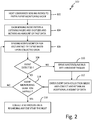
- FIG. 2 is a flowchart illustrating method 100 of collecting data for system 10.
- host 16 commands sensing nodes 12a-12n to enter an event monitoring mode.
- host 16 may specify details for the event monitoring. These details may include, among others, an event monitoring duration and an event type. For example, host 16 may command sensing nodes 12a-12n to monitor for a vibration that exceeds a threshold for a specified time period.
- each sensing node 12a-12n enters a listening mode.
- each sensing node 12a-12n may continuously digitize and retain an amount of past data.
- the rate at which each sensing node 12a-12n samples and retains data may be known by the respective node 12a-12n based upon the event type, or may be specified by host 16 when instructing sensing nodes 12a-12n to enter event monitoring mode, for example.
- the event is monitored for by at least one of sensing nodes 12a-12n. While all sensing nodes 12a-12n may be continually digitizing and retaining data during listening mode, not all sensing nodes 12a-12n may be capable of detecting the specified event. For example, if monitoring for a vibration exceeding a threshold, a temperature sensor may not be able to detect the event. However, temperature data may be desired in conjunction with the vibration data in relation to the event. Thus, all sensing nodes 12a-12n may digitize and retain data, while any number of sensing nodes 12a-12n may be monitoring for occurrence of the specified event.
- step 108 if a sensing node 12a-12n detects an event, or an event is indicated by external systems 18, method 100 proceeds to step 110 and the respective sensing node 12a-12n or host 16 drives master/slave bus 14 with an event trigger.
- the event trigger may be a specified logic state or pattern, for example.
- master/slave bus 14 By driving master/slave bus 14 with a known logic state or pattern, all other sensing nodes 12a-12n, and host 16, can see that an event has been detected by one of sensing nodes 12a-12n or external systems 18. Additionally, if more than one sensing node 12a-12n detects the event, multiple nodes 12a-12n may drive the bus with the event trigger, as the nodes 12a-12n will be driving the same event trigger pattern, which does not result in bus contention.
- sensing nodes 12a-12n enter an event data collection mode in which each sensing node 12a-12n records an amount of event data.
- the amount collected may be known by each of sensing nodes 12a-12n based upon the type of event, or may be specified by host 16 prior to the event detection. This may be any desirable amount of data based upon the detected event.
- step 114 it is determined if an event monitoring duration has expired. If the duration has not expired, method 100 returns to step 106, and each sensing node 12a-12n continues in the listening mode. If the duration has completed, method 100 proceeds to step 116.
- host 16 may obtain the data from sensing nodes 12a-12n regarding the detected event. This data may be preprocessed by one or more of sensing nodes 12a-12n, or may be provided as raw data to host 16. For example, host 16 may request the data one at a time from each individual sensing node 12a-12n over master/slave bus 14. Host 16 may then process the data from sensing nodes 12a-12n to extract individual features regarding the event, for example.
- FIG. 3 is a flowchart illustrating method 200 of collecting data using system 10 according to another embodiment.
- host 16 commands sensing nodes 12a-12n to enter an event monitoring mode.
- host 16 may specify details for the event monitoring. These details may include, among others, an event monitoring duration and an event type. For example, host 16 may command sensing nodes 12a-12n to monitor for a vibration that exceeds a threshold for a specified time period.
- each sensing node 12a-12n enters a listening mode.
- each sensing node 12a-12n may continuously digitize and retain an amount of past data.
- the rate at which each sensing node 12a-12n samples and retains data may be known by the respective node 12a-12n based upon the event type, or may be specified by host 16 when instructing sensing nodes 12a-12n to enter event monitoring mode, for example.
- the event is monitored for by at least one of sensing nodes 12a-12n. While all sensing nodes 12a-12n may be continually digitizing and retaining data during listening mode, not all sensing nodes 12a-12n may be capable of detecting the specified event. For example, if monitoring for a vibration exceeding a threshold, a temperature sensor would not be able to detect the event. However, temperature data may be desired in conjunction with the vibration data in relation to the event. Thus, all sensing nodes 12a-12n digitize and retain data, while any number of sensing nodes 12a-12n may be monitoring for occurrence of the specified event.
- step 208 if a sensing node 12a-12n detects an event, or an event is indicated by external systems 18, method 200 proceeds to step 210 and the respective sensing node 12a-12n or host 16 drives master/slave bus 14 with an event trigger.
- the event trigger may be a specified logic state or pattern, for example.
- master/slave bus 14 By driving master/slave bus 14 with a known logic state or pattern, all other sensing nodes 12a-12n, and host 16, can see that an event has been detected by one of sensing nodes 12a-12n or external systems 18. Additionally, if more than one sensing node 12a-12n detects the event, multiple nodes 12a-12n may drive the bus with the event trigger, as the nodes 12a-12n will be driving the same event trigger pattern, which does not result in bus contention.
- host 16 communicates with each sensing node 12a-12n to determine which respective sensing node 12a-12n detected the event. Host 16 may obtain an event detected status as well as an event time from the respective node 12a-12n. Additionally, host 16 may communicate with each individual sensing node 12a-12n to instruct the respective nodes 12a-12n on how much additional event data should be collected, digitized and retained. At step 214, sensing nodes 12a-12n collect event data based upon the instruction from host 16.
- step 216 it is determined if an event monitoring duration has expired. If the duration has not expired, method 200 returns to step 206, and each sensing node 12a-12n continues in the listening mode. If the duration has completed, method 200 proceeds to step 218.
- host 16 may obtain the data from sensing nodes 12a-12n regarding the detected event. This data may be preprocessed by one or more of sensing nodes 12a-12n, or may be provided as raw data to host 16. For example, host 16 may request the data one at a time from each individual sensing node 12a-12n over master/slave bus 14. Host 16 may then process the data from sensing nodes 12a-12n to extract individual features regarding the event, for example.
Landscapes
- Engineering & Computer Science (AREA)
- Physics & Mathematics (AREA)
- Theoretical Computer Science (AREA)
- General Physics & Mathematics (AREA)
- Computing Systems (AREA)
- General Engineering & Computer Science (AREA)
- Quality & Reliability (AREA)
- Mathematical Physics (AREA)
- Emergency Management (AREA)
- Business, Economics & Management (AREA)
- Computer Security & Cryptography (AREA)
- Signal Processing (AREA)
- Computer Networks & Wireless Communication (AREA)
- Automation & Control Theory (AREA)
- Computer Vision & Pattern Recognition (AREA)
- Arrangements For Transmission Of Measured Signals (AREA)
- Selective Calling Equipment (AREA)
Claims (13)
- Verfahren zur Erfassung von Daten in einem System, das einen Masterknoten (16) und eine Vielzahl von Slave-Abtastknoten (12a-12n) beinhaltet, die über einen Master-/Slave-Datenbus (14) angeschlossen sind, wobei das Verfahren Folgendes umfasst:Befehlen der Vielzahl von Slave-Abtastknoten (12a-12n) durch den Masterknoten (16), in einen Ereignisüberwachungsmodus einzutreten, wobei jeder der Vielzahl von Slave-Abtastknoten (12a-12n) in einen Hörmodus eintritt, wobei die Vielzahl von Slave-Abtastknoten (12a-12n) Eigenschaften einer Umgebung als erste abgetastete Daten während des Hörmodus digitalisiert und speichert;Erkennen eines erkannten Ereignis, das auf die Umgebung bezogen ist, durch einen ersten der Vielzahl von Slave-Abtastknoten unter Verwendung der ersten abgetasteten Daten;Ansteuern eines Ereignisauslösers auf dem Master-/Slave-Datenbus (14) durch den ersten der Vielzahl von Slave-Abtastknoten als Reaktion auf das erkannte Ereignis, wobei der Ereignisauslöser ein bekannter logischer Zustand oder ein bekanntes Logikmuster auf dem Master-/Slave-Datenbus (14) ist;Befehlen einer Vielzahl von Slave-Abtastknoten durch den Masterknoten (16), in einen Ereignisdatenerfassungsmodus einzutreten, nach einem Erkennen des Ereignisauslösers auf dem Master-/Slave-Datenbus;Aufzeichnen von Eigenschaften der Umgebung als zweite abgetastete Daten für eine Zeitdauer, die auf der Art des erkannten Ereignisses basiert, durch die Vielzahl von Slave-Abtastknoten; undSpeichern der zweiten abgetasteten Daten und eines Teils der ersten abgetasteten Daten als Ereignisdaten durch die Vielzahl von Slave-Abtastknoten (12a-12n).
- Verfahren nach Anspruch 1, das ferner Folgendes umfasst:Überwachen des Master-/Slave-Datenbus (14) für den Ereignisauslöser durch den Masterknoten (16); undAufzeichnen einer Ereigniszeit durch den Masterknoten (16), wobei die Ereigniszeit auf einer Systemzeit oder einer Dauer ab einem Beginn des Eintretens in den Ereignisüberwachungsmodus basiert.
- Verfahren nach Anspruch 1 oder 2, das ferner Folgendes umfasst:
Zurückkehren zum Hörmodus nach einem Aufzeichnen von Ereignisdaten durch den ersten der Vielzahl von Slave-Abtastknoten, es sei denn, dass eine Dauer, die mit dem Ereignisüberwachungsmodus verbunden ist, abgelaufen ist oder der Masterknoten (16) dem ersten der Vielzahl von Knoten befohlen hat, den Ereignisüberwachungsmodus zu verlassen. - Verfahren nach Anspruch 1, 2 oder 3, das ferner Folgendes umfasst:
Aufzeichnen des erkannten Ereignisses und einer Ereigniserkennungszeit durch den ersten der Vielzahl von Slave-Abtastknoten, die mit den Ereignisdaten verbunden ist, die auf einer Systemdefinition von Zeit oder einer Dauer ab einem Beginn des Ereignisüberwachungsmodus basieren. - Verfahren nach Anspruch 4, das ferner Folgendes umfasst:Bereitstellen der Ereignisdaten für den Masterknoten (16) durch die Vielzahl von Slave-Abtastknoten (12a-12n); undKorrelieren der Ereignisdaten von der Vielzahl von Slave-Abtastknoten (12a-12n) unter Verwendung der Ereigniserkennungszeit durch den Masterknoten (16).
- Verfahren nach einem der vorhergehenden Ansprüche, das ferner Folgendes umfasst:
Extrahieren individueller Merkmale bezüglich des erkannten Ereignisses unter Nutzung der Ereignisdaten von der Vielzahl von Slave-Abtastknoten (12a-12n) durch den Masterknoten (16). - Verfahren nach einem der vorhergehenden Ansprüche, das ferner Folgendes umfasst:Verarbeiten der Ereignisdaten durch die Vielzahl von Slave-Abtastknoten (12a-12n), um verarbeitete Daten zu erhalten; undBereitstellen der verarbeiteten Daten für den Masterknoten durch die Vielzahl von Slave-Abtastknoten (12a-12n).
- Verfahren nach Anspruch 5, das ferner Folgendes umfasst:
Bestimmen durch den Masterknoten (16), dass der erste der Vielzahl von Slave-Abtastknoten das erkannte Ereignis, das auf einer Ereignisart des erkannten Ereignisses basiert, erkannte. - System, das Folgendes umfasst:einen Master-/Slave-Datenbus;eine Vielzahl von Slave-Abtastknoten; undeinen Masterknoten, der dazu konfiguriert ist, mit der Vielzahl von Slave-Abtastknoten über den Master-/Slave-Datenbus (14) zu kommunizieren, wobei der Masterknoten (16) dazu konfiguriert ist, die Vielzahl von Abtastknoten (12a-12n) in einen Ereignisüberwachungsmodus über den Master-/Slave-Datenbus (14) zu befehlen;wobei die Vielzahl von Slave-Abtastknoten (12a-12n) dazu konfiguriert ist, Eigenschaften einer Umgebung als erste abgetastete Daten während eines Hörmodus des Ereignisüberwachungsmodus zu digitalisieren und speichern und wobei ein erster der Vielzahl von Slave-Abtastknoten unter Verwendung der ersten abgetasteten Daten ein Ereignis erkennt; undwobei der erste der Vielzahl von Slave-Abtastknoten (12a-12n) ferner dazu konfiguriert ist, einen Ereignisauslöser auf dem Master-/Slave-Datenbus (14) nach einem Erkennen des Ereignisses anzusteuern; und wobei der Ereignisauslöser ein bekannter logischer Zustand oder ein bekanntes Logikmuster auf dem Master-/Slave-Datenbus (14) ist; undwobei der Masterknoten (16) ferner dazu konfiguriert ist, einer Vielzahl von Slave-Abtastknoten zu befehlen, in einen Ereignisdatenerfassungsmodus einzutreten und Eigenschaften der Umgebung als zweite abgetastete Daten für eine Zeitdauer zu digitalisieren und speichern, die auf der Art des erkannten Ereignisses basiert, nach einem Erkennen des Ereignisauslösers, der durch einen ersten der Vielzahl von Slave-Abtastknoten auf dem Master-/Slave-Datenbus (14) angesteuert ist, wobei die zweiten abgetasteten Daten und ein Teil der ersten abgetasteten Daten als Ereignisdaten durch die Vielzahl von Slave-Abtastknoten (12a-12n) gespeichert sind.
- System nach Anspruch 9, wobei der Masterknoten (16) dazu konfiguriert ist, eine Ereigniszeit nach einem Erkennen des Ereignisauslösers auf dem Master-/Slave-Datenbus (14) aufzuzeichnen.
- System nach Anspruch 9 oder 10, wobei die Vielzahl von Abtastknoten (12a-12n) dazu konfiguriert sind, eine Ereigniszeit nach einem Erkennen des Ereignisses oder nach einem Erkennen des Ereignisauslösers auf dem Master-/Slave-Datenbus (14) aufzuzeichnen.
- System nach Anspruch 9, 10 oder 11, wobei der Masterknoten (16) dazu konfiguriert ist, die ersten und zweiten abgetasteten Daten von der Vielzahl von Abtastknoten (12a-12n) nach dem Ereignis zu erfassen.
- System nach einem der Ansprüche 9-12, wobei der Masterknoten (16) dazu konfiguriert ist, den Ereignisauslöser auf dem Master-/Slave-Datenbus (14) basierend auf externen Daten anzusteuern, die vom Masterknoten (16) erhalten sind.
Applications Claiming Priority (1)
| Application Number | Priority Date | Filing Date | Title |
|---|---|---|---|
| US15/623,574 US10078955B1 (en) | 2017-06-15 | 2017-06-15 | Event-based data collection for smart sensors on a master/slave bus |
Publications (2)
| Publication Number | Publication Date |
|---|---|
| EP3422189A1 EP3422189A1 (de) | 2019-01-02 |
| EP3422189B1 true EP3422189B1 (de) | 2020-11-18 |
Family
ID=62837558
Family Applications (1)
| Application Number | Title | Priority Date | Filing Date |
|---|---|---|---|
| EP18177928.1A Active EP3422189B1 (de) | 2017-06-15 | 2018-06-15 | Ereignisbasierte datenerfassung für intelligente sensoren auf einem master-slave-bus |
Country Status (2)
| Country | Link |
|---|---|
| US (1) | US10078955B1 (de) |
| EP (1) | EP3422189B1 (de) |
Families Citing this family (9)
| Publication number | Priority date | Publication date | Assignee | Title |
|---|---|---|---|---|
| KR102150068B1 (ko) * | 2017-12-21 | 2020-08-31 | 주식회사 엘지화학 | 통신 진단 장치 및 방법 |
| US10728633B2 (en) * | 2018-12-19 | 2020-07-28 | Simmonds Precision Products, Inc. | Configurable distributed smart sensor system |
| JP6956347B2 (ja) | 2019-01-31 | 2021-11-02 | 株式会社安川電機 | トレースデータ取得システム、トレースデータ取得方法、及びプログラム |
| US10938643B2 (en) | 2019-02-08 | 2021-03-02 | Simmonds Precision Products, Inc. | Distributed sensing systems and nodes therefor |
| US11243098B2 (en) | 2019-02-08 | 2022-02-08 | Simmonds Precision Products, Inc. | Configurable nodes for sensing systems |
| DE102019218574A1 (de) * | 2019-11-29 | 2021-06-02 | Airbus Operations Gmbh | Konfigurationsmanagement für avioniknetzwerk und verfahren zum überprüfen der konfiguration eines avioniknetzwerks |
| US11210920B2 (en) * | 2020-01-21 | 2021-12-28 | Simmonds Precision Products, Inc. | Configurable parent-child switch |
| US12413942B2 (en) * | 2020-03-21 | 2025-09-09 | Trackonomy Systems, Inc. | Distributed intelligent software for vibration and acoustic monitoring and systems and methods implementing the same |
| US20250181441A1 (en) * | 2023-11-30 | 2025-06-05 | Dell Products, L.P. | DIAGNOSING ACCIDENTS IN INFORMATION HANDLING SYSTEMS (IHSs) |
Family Cites Families (17)
| Publication number | Priority date | Publication date | Assignee | Title |
|---|---|---|---|---|
| US4928246A (en) * | 1988-10-21 | 1990-05-22 | Iowa State University Research Foundation, Inc. | Multiple channel data acquisition system |
| US5195046A (en) * | 1989-01-10 | 1993-03-16 | Gerardi Joseph J | Method and apparatus for structural integrity monitoring |
| IL117792A (en) * | 1995-05-08 | 2003-10-31 | Rafael Armament Dev Authority | Autonomous command and control unit for mobile platform |
| US7023913B1 (en) * | 2000-06-14 | 2006-04-04 | Monroe David A | Digital security multimedia sensor |
| US6545601B1 (en) * | 1999-02-25 | 2003-04-08 | David A. Monroe | Ground based security surveillance system for aircraft and other commercial vehicles |
| US8140658B1 (en) | 1999-10-06 | 2012-03-20 | Borgia/Cummins, Llc | Apparatus for internetworked wireless integrated network sensors (WINS) |
| US9729342B2 (en) * | 2010-12-20 | 2017-08-08 | Icontrol Networks, Inc. | Defining and implementing sensor triggered response rules |
| US7486495B1 (en) | 2005-05-25 | 2009-02-03 | Cameron International Corporation | Networked series of sensors having distributed measurement and control for use in a hazardous environment |
| US7398186B2 (en) * | 2005-08-17 | 2008-07-08 | Xtek, Inc. | Data acquisition system for system monitoring |
| US9325951B2 (en) * | 2008-03-03 | 2016-04-26 | Avigilon Patent Holding 2 Corporation | Content-aware computer networking devices with video analytics for reducing video storage and video communication bandwidth requirements of a video surveillance network camera system |
| US9235765B2 (en) * | 2010-08-26 | 2016-01-12 | Blast Motion Inc. | Video and motion event integration system |
| US20140210620A1 (en) * | 2013-01-25 | 2014-07-31 | Ultraclenz Llc | Wireless communication for dispenser beacons |
| US9133019B2 (en) | 2013-12-03 | 2015-09-15 | Barry John McCleland | Sensor probe and related systems and methods |
| EP2939532A1 (de) * | 2014-04-17 | 2015-11-04 | MILKLINE S.r.l. | Durch einen computer implementiertes verfahren für die steuerung von melkvorgängen in automatisierten systemen |
| US9734693B2 (en) * | 2014-07-09 | 2017-08-15 | Mckinley Equipment Corporation | Remote equipment monitoring and notification using a server system |
| FR3025035B1 (fr) * | 2014-08-22 | 2016-09-09 | Jtekt Europe Sas | Calculateur pour vehicule, tel qu’un calculateur de direction assistee, pourvu d’un enregistreur d’evenements integre |
| JP5866540B1 (ja) * | 2014-11-21 | 2016-02-17 | パナソニックIpマネジメント株式会社 | 監視システム及び監視システムにおける監視方法 |
-
2017
- 2017-06-15 US US15/623,574 patent/US10078955B1/en active Active
-
2018
- 2018-06-15 EP EP18177928.1A patent/EP3422189B1/de active Active
Non-Patent Citations (1)
| Title |
|---|
| None * |
Also Published As
| Publication number | Publication date |
|---|---|
| US10078955B1 (en) | 2018-09-18 |
| EP3422189A1 (de) | 2019-01-02 |
Similar Documents
| Publication | Publication Date | Title |
|---|---|---|
| EP3422189B1 (de) | Ereignisbasierte datenerfassung für intelligente sensoren auf einem master-slave-bus | |
| EP3447644B1 (de) | Ereignisbasierte datensammlung für intelligente sensoren auf einem arbitrierungsbus | |
| US11727732B2 (en) | Preserving vehicular raw vibration data for post-event analysis | |
| US10713866B2 (en) | Vehicle operation data collection apparatus, vehicle operation data collection system, and vehicle operation data collection method | |
| US10181976B2 (en) | System and method of adjusting data collection frequency | |
| CN107614215B (zh) | 故障诊断装置及故障诊断方法 | |
| US12097977B2 (en) | System for monitoring the health of a helicopter | |
| CN109396954A (zh) | 嵌入式主轴系统异常状态智能检测和信息推送装置 | |
| EP4057513A1 (de) | Sensordatenverarbeitung für zustandsüberwachungssysteme | |
| US20160246274A1 (en) | Control apparatus for giving notification of maintenance and inspection times of signal-controlled peripheral devices | |
| US10981675B2 (en) | Propeller balancing using inflight data | |
| CN108398926B (zh) | 监视装置以及监视系统 | |
| KR101969865B1 (ko) | 설비 관리용 센서 신호의 오류 검출 방법 및 그 방법이 적용된 설비 관리 시스템 | |
| JP6139149B2 (ja) | 解析方法および解析装置 | |
| EP2974925A1 (de) | Kraftbefehlsaktualisierungsratenerkennung | |
| US11601454B2 (en) | Work machine and method for monitoring a control system at a work machine | |
| JPH066866A (ja) | プラント監視システム | |
| CN112598816A (zh) | 一种车辆数据采集方法、装置及车辆诊断系统 | |
| CN112215981A (zh) | 一种数据记录设备及轨道车辆 | |
| EP4393782A1 (de) | Fehlerdiagnosesystem für ein flugzeugbremssystem | |
| CN113701872B (zh) | 一种用于振动保护的数据同步方法及系统 | |
| EP3871972B1 (de) | Propellerausgleich mittels flugdaten | |
| KR101318666B1 (ko) | 차량용 디지털 운행 기록계 및 그의 수집 방법 | |
| JP2932507B2 (ja) | 異常検出装置 | |
| JPS6325754B2 (de) |
Legal Events
| Date | Code | Title | Description |
|---|---|---|---|
| PUAI | Public reference made under article 153(3) epc to a published international application that has entered the european phase |
Free format text: ORIGINAL CODE: 0009012 |
|
| STAA | Information on the status of an ep patent application or granted ep patent |
Free format text: STATUS: THE APPLICATION HAS BEEN PUBLISHED |
|
| AK | Designated contracting states |
Kind code of ref document: A1 Designated state(s): AL AT BE BG CH CY CZ DE DK EE ES FI FR GB GR HR HU IE IS IT LI LT LU LV MC MK MT NL NO PL PT RO RS SE SI SK SM TR |
|
| AX | Request for extension of the european patent |
Extension state: BA ME |
|
| STAA | Information on the status of an ep patent application or granted ep patent |
Free format text: STATUS: REQUEST FOR EXAMINATION WAS MADE |
|
| 17P | Request for examination filed |
Effective date: 20190702 |
|
| RBV | Designated contracting states (corrected) |
Designated state(s): AL AT BE BG CH CY CZ DE DK EE ES FI FR GB GR HR HU IE IS IT LI LT LU LV MC MK MT NL NO PL PT RO RS SE SI SK SM TR |
|
| RIC1 | Information provided on ipc code assigned before grant |
Ipc: G08B 25/04 20060101ALI20200422BHEP Ipc: G06F 11/30 20060101AFI20200422BHEP Ipc: G05B 19/042 20060101ALI20200422BHEP Ipc: G07C 3/00 20060101ALN20200422BHEP Ipc: H04L 12/403 20060101ALI20200422BHEP Ipc: G06F 11/07 20060101ALN20200422BHEP Ipc: G06F 11/34 20060101ALN20200422BHEP |
|
| GRAP | Despatch of communication of intention to grant a patent |
Free format text: ORIGINAL CODE: EPIDOSNIGR1 |
|
| STAA | Information on the status of an ep patent application or granted ep patent |
Free format text: STATUS: GRANT OF PATENT IS INTENDED |
|
| RIC1 | Information provided on ipc code assigned before grant |
Ipc: G05B 19/042 20060101ALI20200528BHEP Ipc: G06F 11/30 20060101AFI20200528BHEP Ipc: G06F 11/07 20060101ALN20200528BHEP Ipc: G07C 3/00 20060101ALN20200528BHEP Ipc: G08B 25/04 20060101ALI20200528BHEP Ipc: G06F 11/34 20060101ALN20200528BHEP Ipc: H04L 12/403 20060101ALI20200528BHEP |
|
| INTG | Intention to grant announced |
Effective date: 20200623 |
|
| GRAS | Grant fee paid |
Free format text: ORIGINAL CODE: EPIDOSNIGR3 |
|
| GRAA | (expected) grant |
Free format text: ORIGINAL CODE: 0009210 |
|
| STAA | Information on the status of an ep patent application or granted ep patent |
Free format text: STATUS: THE PATENT HAS BEEN GRANTED |
|
| AK | Designated contracting states |
Kind code of ref document: B1 Designated state(s): AL AT BE BG CH CY CZ DE DK EE ES FI FR GB GR HR HU IE IS IT LI LT LU LV MC MK MT NL NO PL PT RO RS SE SI SK SM TR |
|
| REG | Reference to a national code |
Ref country code: GB Ref legal event code: FG4D |
|
| REG | Reference to a national code |
Ref country code: CH Ref legal event code: EP |
|
| REG | Reference to a national code |
Ref country code: IE Ref legal event code: FG4D |
|
| REG | Reference to a national code |
Ref country code: DE Ref legal event code: R096 Ref document number: 602018009762 Country of ref document: DE |
|
| REG | Reference to a national code |
Ref country code: AT Ref legal event code: REF Ref document number: 1336513 Country of ref document: AT Kind code of ref document: T Effective date: 20201215 |
|
| REG | Reference to a national code |
Ref country code: AT Ref legal event code: MK05 Ref document number: 1336513 Country of ref document: AT Kind code of ref document: T Effective date: 20201118 |
|
| REG | Reference to a national code |
Ref country code: NL Ref legal event code: MP Effective date: 20201118 |
|
| PG25 | Lapsed in a contracting state [announced via postgrant information from national office to epo] |
Ref country code: GR Free format text: LAPSE BECAUSE OF FAILURE TO SUBMIT A TRANSLATION OF THE DESCRIPTION OR TO PAY THE FEE WITHIN THE PRESCRIBED TIME-LIMIT Effective date: 20210219 Ref country code: NO Free format text: LAPSE BECAUSE OF FAILURE TO SUBMIT A TRANSLATION OF THE DESCRIPTION OR TO PAY THE FEE WITHIN THE PRESCRIBED TIME-LIMIT Effective date: 20210218 Ref country code: FI Free format text: LAPSE BECAUSE OF FAILURE TO SUBMIT A TRANSLATION OF THE DESCRIPTION OR TO PAY THE FEE WITHIN THE PRESCRIBED TIME-LIMIT Effective date: 20201118 Ref country code: RS Free format text: LAPSE BECAUSE OF FAILURE TO SUBMIT A TRANSLATION OF THE DESCRIPTION OR TO PAY THE FEE WITHIN THE PRESCRIBED TIME-LIMIT Effective date: 20201118 Ref country code: PT Free format text: LAPSE BECAUSE OF FAILURE TO SUBMIT A TRANSLATION OF THE DESCRIPTION OR TO PAY THE FEE WITHIN THE PRESCRIBED TIME-LIMIT Effective date: 20210318 |
|
| PG25 | Lapsed in a contracting state [announced via postgrant information from national office to epo] |
Ref country code: AT Free format text: LAPSE BECAUSE OF FAILURE TO SUBMIT A TRANSLATION OF THE DESCRIPTION OR TO PAY THE FEE WITHIN THE PRESCRIBED TIME-LIMIT Effective date: 20201118 Ref country code: SE Free format text: LAPSE BECAUSE OF FAILURE TO SUBMIT A TRANSLATION OF THE DESCRIPTION OR TO PAY THE FEE WITHIN THE PRESCRIBED TIME-LIMIT Effective date: 20201118 Ref country code: PL Free format text: LAPSE BECAUSE OF FAILURE TO SUBMIT A TRANSLATION OF THE DESCRIPTION OR TO PAY THE FEE WITHIN THE PRESCRIBED TIME-LIMIT Effective date: 20201118 Ref country code: LV Free format text: LAPSE BECAUSE OF FAILURE TO SUBMIT A TRANSLATION OF THE DESCRIPTION OR TO PAY THE FEE WITHIN THE PRESCRIBED TIME-LIMIT Effective date: 20201118 Ref country code: IS Free format text: LAPSE BECAUSE OF FAILURE TO SUBMIT A TRANSLATION OF THE DESCRIPTION OR TO PAY THE FEE WITHIN THE PRESCRIBED TIME-LIMIT Effective date: 20210318 Ref country code: BG Free format text: LAPSE BECAUSE OF FAILURE TO SUBMIT A TRANSLATION OF THE DESCRIPTION OR TO PAY THE FEE WITHIN THE PRESCRIBED TIME-LIMIT Effective date: 20210218 |
|
| REG | Reference to a national code |
Ref country code: LT Ref legal event code: MG9D |
|
| PG25 | Lapsed in a contracting state [announced via postgrant information from national office to epo] |
Ref country code: HR Free format text: LAPSE BECAUSE OF FAILURE TO SUBMIT A TRANSLATION OF THE DESCRIPTION OR TO PAY THE FEE WITHIN THE PRESCRIBED TIME-LIMIT Effective date: 20201118 |
|
| PG25 | Lapsed in a contracting state [announced via postgrant information from national office to epo] |
Ref country code: LT Free format text: LAPSE BECAUSE OF FAILURE TO SUBMIT A TRANSLATION OF THE DESCRIPTION OR TO PAY THE FEE WITHIN THE PRESCRIBED TIME-LIMIT Effective date: 20201118 Ref country code: RO Free format text: LAPSE BECAUSE OF FAILURE TO SUBMIT A TRANSLATION OF THE DESCRIPTION OR TO PAY THE FEE WITHIN THE PRESCRIBED TIME-LIMIT Effective date: 20201118 Ref country code: SK Free format text: LAPSE BECAUSE OF FAILURE TO SUBMIT A TRANSLATION OF THE DESCRIPTION OR TO PAY THE FEE WITHIN THE PRESCRIBED TIME-LIMIT Effective date: 20201118 Ref country code: SM Free format text: LAPSE BECAUSE OF FAILURE TO SUBMIT A TRANSLATION OF THE DESCRIPTION OR TO PAY THE FEE WITHIN THE PRESCRIBED TIME-LIMIT Effective date: 20201118 Ref country code: EE Free format text: LAPSE BECAUSE OF FAILURE TO SUBMIT A TRANSLATION OF THE DESCRIPTION OR TO PAY THE FEE WITHIN THE PRESCRIBED TIME-LIMIT Effective date: 20201118 Ref country code: CZ Free format text: LAPSE BECAUSE OF FAILURE TO SUBMIT A TRANSLATION OF THE DESCRIPTION OR TO PAY THE FEE WITHIN THE PRESCRIBED TIME-LIMIT Effective date: 20201118 |
|
| REG | Reference to a national code |
Ref country code: DE Ref legal event code: R097 Ref document number: 602018009762 Country of ref document: DE |
|
| PG25 | Lapsed in a contracting state [announced via postgrant information from national office to epo] |
Ref country code: DK Free format text: LAPSE BECAUSE OF FAILURE TO SUBMIT A TRANSLATION OF THE DESCRIPTION OR TO PAY THE FEE WITHIN THE PRESCRIBED TIME-LIMIT Effective date: 20201118 |
|
| PLBE | No opposition filed within time limit |
Free format text: ORIGINAL CODE: 0009261 |
|
| STAA | Information on the status of an ep patent application or granted ep patent |
Free format text: STATUS: NO OPPOSITION FILED WITHIN TIME LIMIT |
|
| 26N | No opposition filed |
Effective date: 20210819 |
|
| PG25 | Lapsed in a contracting state [announced via postgrant information from national office to epo] |
Ref country code: AL Free format text: LAPSE BECAUSE OF FAILURE TO SUBMIT A TRANSLATION OF THE DESCRIPTION OR TO PAY THE FEE WITHIN THE PRESCRIBED TIME-LIMIT Effective date: 20201118 Ref country code: NL Free format text: LAPSE BECAUSE OF FAILURE TO SUBMIT A TRANSLATION OF THE DESCRIPTION OR TO PAY THE FEE WITHIN THE PRESCRIBED TIME-LIMIT Effective date: 20201118 Ref country code: IT Free format text: LAPSE BECAUSE OF FAILURE TO SUBMIT A TRANSLATION OF THE DESCRIPTION OR TO PAY THE FEE WITHIN THE PRESCRIBED TIME-LIMIT Effective date: 20201118 |
|
| PG25 | Lapsed in a contracting state [announced via postgrant information from national office to epo] |
Ref country code: SI Free format text: LAPSE BECAUSE OF FAILURE TO SUBMIT A TRANSLATION OF THE DESCRIPTION OR TO PAY THE FEE WITHIN THE PRESCRIBED TIME-LIMIT Effective date: 20201118 |
|
| PG25 | Lapsed in a contracting state [announced via postgrant information from national office to epo] |
Ref country code: ES Free format text: LAPSE BECAUSE OF FAILURE TO SUBMIT A TRANSLATION OF THE DESCRIPTION OR TO PAY THE FEE WITHIN THE PRESCRIBED TIME-LIMIT Effective date: 20201118 Ref country code: MC Free format text: LAPSE BECAUSE OF FAILURE TO SUBMIT A TRANSLATION OF THE DESCRIPTION OR TO PAY THE FEE WITHIN THE PRESCRIBED TIME-LIMIT Effective date: 20201118 |
|
| REG | Reference to a national code |
Ref country code: CH Ref legal event code: PL |
|
| REG | Reference to a national code |
Ref country code: BE Ref legal event code: MM Effective date: 20210630 |
|
| PG25 | Lapsed in a contracting state [announced via postgrant information from national office to epo] |
Ref country code: LU Free format text: LAPSE BECAUSE OF NON-PAYMENT OF DUE FEES Effective date: 20210615 |
|
| PG25 | Lapsed in a contracting state [announced via postgrant information from national office to epo] |
Ref country code: LI Free format text: LAPSE BECAUSE OF NON-PAYMENT OF DUE FEES Effective date: 20210630 Ref country code: IE Free format text: LAPSE BECAUSE OF NON-PAYMENT OF DUE FEES Effective date: 20210615 Ref country code: CH Free format text: LAPSE BECAUSE OF NON-PAYMENT OF DUE FEES Effective date: 20210630 |
|
| PG25 | Lapsed in a contracting state [announced via postgrant information from national office to epo] |
Ref country code: IS Free format text: LAPSE BECAUSE OF FAILURE TO SUBMIT A TRANSLATION OF THE DESCRIPTION OR TO PAY THE FEE WITHIN THE PRESCRIBED TIME-LIMIT Effective date: 20210318 |
|
| PG25 | Lapsed in a contracting state [announced via postgrant information from national office to epo] |
Ref country code: BE Free format text: LAPSE BECAUSE OF NON-PAYMENT OF DUE FEES Effective date: 20210630 |
|
| PG25 | Lapsed in a contracting state [announced via postgrant information from national office to epo] |
Ref country code: CY Free format text: LAPSE BECAUSE OF FAILURE TO SUBMIT A TRANSLATION OF THE DESCRIPTION OR TO PAY THE FEE WITHIN THE PRESCRIBED TIME-LIMIT Effective date: 20201118 |
|
| PG25 | Lapsed in a contracting state [announced via postgrant information from national office to epo] |
Ref country code: HU Free format text: LAPSE BECAUSE OF FAILURE TO SUBMIT A TRANSLATION OF THE DESCRIPTION OR TO PAY THE FEE WITHIN THE PRESCRIBED TIME-LIMIT; INVALID AB INITIO Effective date: 20180615 |
|
| PG25 | Lapsed in a contracting state [announced via postgrant information from national office to epo] |
Ref country code: MK Free format text: LAPSE BECAUSE OF FAILURE TO SUBMIT A TRANSLATION OF THE DESCRIPTION OR TO PAY THE FEE WITHIN THE PRESCRIBED TIME-LIMIT Effective date: 20201118 |
|
| REG | Reference to a national code |
Ref country code: DE Ref legal event code: R081 Ref document number: 602018009762 Country of ref document: DE Owner name: ROCKWELL COLLINS, INC., CEDAR RAPIDS, US Free format text: FORMER OWNER: SIMMONDS PRECISION PRODUCTS, INC., VERGENNES, VT., US |
|
| REG | Reference to a national code |
Ref country code: GB Ref legal event code: 732E Free format text: REGISTERED BETWEEN 20240509 AND 20240515 |
|
| PG25 | Lapsed in a contracting state [announced via postgrant information from national office to epo] |
Ref country code: TR Free format text: LAPSE BECAUSE OF FAILURE TO SUBMIT A TRANSLATION OF THE DESCRIPTION OR TO PAY THE FEE WITHIN THE PRESCRIBED TIME-LIMIT Effective date: 20201118 |
|
| PG25 | Lapsed in a contracting state [announced via postgrant information from national office to epo] |
Ref country code: MT Free format text: LAPSE BECAUSE OF FAILURE TO SUBMIT A TRANSLATION OF THE DESCRIPTION OR TO PAY THE FEE WITHIN THE PRESCRIBED TIME-LIMIT Effective date: 20201118 |
|
| PGFP | Annual fee paid to national office [announced via postgrant information from national office to epo] |
Ref country code: DE Payment date: 20250520 Year of fee payment: 8 |
|
| PGFP | Annual fee paid to national office [announced via postgrant information from national office to epo] |
Ref country code: GB Payment date: 20250520 Year of fee payment: 8 |
|
| PGFP | Annual fee paid to national office [announced via postgrant information from national office to epo] |
Ref country code: FR Payment date: 20250520 Year of fee payment: 8 |