EP3422080A1 - Screen and head-up display device - Google Patents
Screen and head-up display device Download PDFInfo
- Publication number
- EP3422080A1 EP3422080A1 EP17756640.3A EP17756640A EP3422080A1 EP 3422080 A1 EP3422080 A1 EP 3422080A1 EP 17756640 A EP17756640 A EP 17756640A EP 3422080 A1 EP3422080 A1 EP 3422080A1
- Authority
- EP
- European Patent Office
- Prior art keywords
- thickness
- combiner
- regard
- main body
- body layer
- Prior art date
- Legal status (The legal status is an assumption and is not a legal conclusion. Google has not performed a legal analysis and makes no representation as to the accuracy of the status listed.)
- Granted
Links
Images





Classifications
-
- G—PHYSICS
- G02—OPTICS
- G02B—OPTICAL ELEMENTS, SYSTEMS OR APPARATUS
- G02B27/00—Optical systems or apparatus not provided for by any of the groups G02B1/00 - G02B26/00, G02B30/00
- G02B27/01—Head-up displays
- G02B27/0101—Head-up displays characterised by optical features
-
- B—PERFORMING OPERATIONS; TRANSPORTING
- B60—VEHICLES IN GENERAL
- B60K—ARRANGEMENT OR MOUNTING OF PROPULSION UNITS OR OF TRANSMISSIONS IN VEHICLES; ARRANGEMENT OR MOUNTING OF PLURAL DIVERSE PRIME-MOVERS IN VEHICLES; AUXILIARY DRIVES FOR VEHICLES; INSTRUMENTATION OR DASHBOARDS FOR VEHICLES; ARRANGEMENTS IN CONNECTION WITH COOLING, AIR INTAKE, GAS EXHAUST OR FUEL SUPPLY OF PROPULSION UNITS IN VEHICLES
- B60K35/00—Instruments specially adapted for vehicles; Arrangement of instruments in or on vehicles
- B60K35/20—Output arrangements, i.e. from vehicle to user, associated with vehicle functions or specially adapted therefor
- B60K35/21—Output arrangements, i.e. from vehicle to user, associated with vehicle functions or specially adapted therefor using visual output, e.g. blinking lights or matrix displays
- B60K35/23—Head-up displays [HUD]
- B60K35/231—Head-up displays [HUD] characterised by their arrangement or structure for integration into vehicles
-
- B—PERFORMING OPERATIONS; TRANSPORTING
- B60—VEHICLES IN GENERAL
- B60K—ARRANGEMENT OR MOUNTING OF PROPULSION UNITS OR OF TRANSMISSIONS IN VEHICLES; ARRANGEMENT OR MOUNTING OF PLURAL DIVERSE PRIME-MOVERS IN VEHICLES; AUXILIARY DRIVES FOR VEHICLES; INSTRUMENTATION OR DASHBOARDS FOR VEHICLES; ARRANGEMENTS IN CONNECTION WITH COOLING, AIR INTAKE, GAS EXHAUST OR FUEL SUPPLY OF PROPULSION UNITS IN VEHICLES
- B60K35/00—Instruments specially adapted for vehicles; Arrangement of instruments in or on vehicles
- B60K35/60—Instruments characterised by their location or relative disposition in or on vehicles
-
- G—PHYSICS
- G03—PHOTOGRAPHY; CINEMATOGRAPHY; ANALOGOUS TECHNIQUES USING WAVES OTHER THAN OPTICAL WAVES; ELECTROGRAPHY; HOLOGRAPHY
- G03B—APPARATUS OR ARRANGEMENTS FOR TAKING PHOTOGRAPHS OR FOR PROJECTING OR VIEWING THEM; APPARATUS OR ARRANGEMENTS EMPLOYING ANALOGOUS TECHNIQUES USING WAVES OTHER THAN OPTICAL WAVES; ACCESSORIES THEREFOR
- G03B21/00—Projectors or projection-type viewers; Accessories therefor
- G03B21/54—Accessories
- G03B21/56—Projection screens
-
- G—PHYSICS
- G03—PHOTOGRAPHY; CINEMATOGRAPHY; ANALOGOUS TECHNIQUES USING WAVES OTHER THAN OPTICAL WAVES; ELECTROGRAPHY; HOLOGRAPHY
- G03B—APPARATUS OR ARRANGEMENTS FOR TAKING PHOTOGRAPHS OR FOR PROJECTING OR VIEWING THEM; APPARATUS OR ARRANGEMENTS EMPLOYING ANALOGOUS TECHNIQUES USING WAVES OTHER THAN OPTICAL WAVES; ACCESSORIES THEREFOR
- G03B21/00—Projectors or projection-type viewers; Accessories therefor
- G03B21/54—Accessories
- G03B21/56—Projection screens
- G03B21/60—Projection screens characterised by the nature of the surface
-
- B—PERFORMING OPERATIONS; TRANSPORTING
- B60—VEHICLES IN GENERAL
- B60K—ARRANGEMENT OR MOUNTING OF PROPULSION UNITS OR OF TRANSMISSIONS IN VEHICLES; ARRANGEMENT OR MOUNTING OF PLURAL DIVERSE PRIME-MOVERS IN VEHICLES; AUXILIARY DRIVES FOR VEHICLES; INSTRUMENTATION OR DASHBOARDS FOR VEHICLES; ARRANGEMENTS IN CONNECTION WITH COOLING, AIR INTAKE, GAS EXHAUST OR FUEL SUPPLY OF PROPULSION UNITS IN VEHICLES
- B60K2360/00—Indexing scheme associated with groups B60K35/00 or B60K37/00 relating to details of instruments or dashboards
- B60K2360/20—Optical features of instruments
- B60K2360/23—Optical features of instruments using reflectors
-
- G—PHYSICS
- G02—OPTICS
- G02B—OPTICAL ELEMENTS, SYSTEMS OR APPARATUS
- G02B27/00—Optical systems or apparatus not provided for by any of the groups G02B1/00 - G02B26/00, G02B30/00
- G02B27/01—Head-up displays
- G02B27/0101—Head-up displays characterised by optical features
- G02B2027/0118—Head-up displays characterised by optical features comprising devices for improving the contrast of the display / brillance control visibility
- G02B2027/012—Head-up displays characterised by optical features comprising devices for improving the contrast of the display / brillance control visibility comprising devices for attenuating parasitic image effects
-
- G—PHYSICS
- G02—OPTICS
- G02B—OPTICAL ELEMENTS, SYSTEMS OR APPARATUS
- G02B27/00—Optical systems or apparatus not provided for by any of the groups G02B1/00 - G02B26/00, G02B30/00
- G02B27/01—Head-up displays
- G02B27/0101—Head-up displays characterised by optical features
- G02B2027/013—Head-up displays characterised by optical features comprising a combiner of particular shape, e.g. curvature
-
- G—PHYSICS
- G02—OPTICS
- G02B—OPTICAL ELEMENTS, SYSTEMS OR APPARATUS
- G02B27/00—Optical systems or apparatus not provided for by any of the groups G02B1/00 - G02B26/00, G02B30/00
- G02B27/01—Head-up displays
- G02B2027/0192—Supplementary details
- G02B2027/0194—Supplementary details with combiner of laminated type, for optical or mechanical aspects
Definitions
- the present invention relates to a screen for displaying an image at the end of the line of sight and a head-up display device having incorporated therein.
- a head-up display device is capable of displaying information in a manner overlapped with the background at the end of the line of sight. Incorporating such a head-up display device, for example, in an automobile allows for projecting, at the end of the line of sight such as a windshield, an image including information such as speed obtained by instruments in the vehicle while driving the automobile, which facilitates driving without changing the eyesight and may lead to accident prevention.
- the combiner according to Patent Literatures 1 and 2 has not sufficiently taken into consideration of the thickness of the lateral section and, even when the double image of the image in the vertical direction at the central part with regard to the lateral direction is dissolved, the double image in the periphery with regard to the lateral direction is not sufficiently dissolved, thereby resulting in degradation of the image quality as a whole. Particularly, significant degradation of the image quality occurs in the case with a wide viewing angle and a wide eye box.
- a screen for a head-up display device that reflects an aspect of the present invention has a main body layer sandwiched between a first concave optical surface located at an observation side and a second convex optical surface located at a side opposite to the observation side, wherein the thickness of the main body layer becomes thinner from the center toward the periphery with regard to a lateral direction which is perpendicular to a reference plane, and variation of the thickness of the main body layer with regard to a vertical direction parallel to the reference plane is different between the central part and the peripheral part with regard to the lateral direction.
- the reference plane is a plane including an optical axis, and becomes a vertical plane when display light is incident from an upward or downward direction.
- the thickness of the main body layer relates to the direction parallel to the normal direction of the first optical surface at the center.
- the lateral direction is not limited to the horizontal direction.
- the head-up display device reflecting an aspect of the present invention includes the aforementioned screen and a drawing unit that projects display light on the screen.
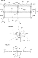
- Figs. 1A and 1B are a conceptual side cross-sectional view and a front view illustrating a head-up display device 100 of the present embodiment and its usage state.
- the head-up display device 100 which is intended to be mounted on in a vehicle body 2, includes a drawing unit 10 and a combiner 20.
- the drawing unit 10 which is provided so as to be embedded in a dashboard 4 of the vehicle body 2, emits display light HK corresponding to an image including driving-related information toward the combiner 20.
- the combiner 20, which is a screen that functions as a semi-transparent concave mirror and provided in an upright manner on the dashboard 4 in a manner supported by a lower part end, reflects the display light HK from the drawing unit 10 to the backward of the vehicle body 2.
- the combiner 20 turns out to be a stand-alone type provided separately from a windshield 8.
- the display light HK reflected by the combiner (screen) 20 is guided to an eye box corresponding to a pupil HT and its peripheral position of a driver UN.
- the driver UN is allowed to observe the display light HK reflected by the combiner 20, i.e., a display image IM as a virtual image located ahead of the vehicle body 2.
- the driver UN is allowed to observe outside light transmitted through the combiner 20, i.e., a real image such as a scenery ahead.
- the driver UN is allowed to observe the display image (virtual image) IM including driving-related information formed by reflection of the display light HK by the combiner 20, in a manner overlapped with an outside image behind the combiner 20.
- Fig. 2 is a cross-sectional view illustrating an enlarged view of the head-up display device 100.
- the drawing unit 10 has a drawing device 12 including liquid crystal display panel 11, a mirror 13, and a housing 14.
- the drawing device 12 has, besides the liquid crystal display panel 11, a display driving circuit that causes the liquid crystal display panel 11 to perform a display operation, a light source such as LED or the like that emits light for illuminating the liquid crystal display panel 11, and an optical equalization system or the like to that equalizes light from such a light source, although detailed description thereof being omitted.
- the mirror 13 may be convex, concave, or planar and, in the case of a curved surface, may be an aspheric surface, a free-form surface, or the like, without being limited to a spherical surface.
- the housing 14 has an aperture 14a that allows transmission of the display light HK therethrough, and the aperture 14a may have a film- or thin-sheet light transmission member 15 provided thereon.
- the combiner 20 which is a plate-like member, has a first optical surface 21 provided at the observing side or a seat 6 (see Fig. 1A ) side where the driver UN is sitting as the observer, and a second optical surface 22 provided at a side opposite to the observation side or at a side of the windshield 8.
- the first optical surface 21, being a concave curved surface turns out to be an aspheric surface or a free-form surface.
- the first optical surface 21 has been obtained by forming a half-mirror coating 20b having a reflectivity of 20 to 30%, for example, on a main body layer 20a, which is a base member, and allows for transmitting outside light GK therethrough to a desired degree while reflecting the display light HK as appropriate.
- the second optical surface 22 turns out to have the main body layer 20a exposed therefrom without forming anti-reflection film (or anti-reflection coating). In such a case, it is possible to suppress formation of a double image while reducing cost by omitting the anti-reflection coating.
- the second optical surface 22 may also have anti-reflection film formed thereon, or may be covered with protection coating.
- Figs. 3A to 3C are a front view of the combiner (screen) 20, a cross-sectional view seen from arrow AA, and a cross-sectional view seen from arrow BB.
- the combiner 20 is divided laterally into two parts by a virtual reference plane SH1 including an optical axis AX passing through a center C1, and a laterally symmetrical in shape.
- the intersecting surface SH2 is a surface perpendicular to the reference plane SH1 and passing through the center C1, and is also a surface parallel to the ⁇ - ⁇ surface.
- the optical axis AX is considered on the basis of the display light HK passing through the center C1 of the combiner 20 and guided to the center of an eye box SY (see Fig. 4C ).
- the combiner 20 in the drawing illustrates only an optically effective region, and may have a frame part 20z around the effective region.
- the center C1 of the combiner 20 is the optical center and does not necessarily coincide with the center of contour.
- a central vertically-crossing zone 20i which is a central part with regard to the lateral direction D2, is a part where the combiner 20 intersects with the reference plane SH1 or the vertical plane passing through the center C1.
- the central vertically-crossing zone 20i which is curved as a whole in the longitudinal direction, extends in a vertical direction D1 inclined against the vertical ⁇ -axis direction.
- a pair of peripheral parts 20j and 20k with regard to a lateral direction D2 are separated at both ends in the ⁇ axis directions, and extend generally parallel to the central vertically-crossing zone 20i, both being curved as a whole in the longitudinal direction.
- a central laterally-crossing zone 20p which is the central part with regard to the vertical direction D1 is a part where the combiner 20 intersects with the intersecting surface SH2, is curved as a whole in the longitudinal direction.
- a pair of upper and lower vertical ends 20q and 20r sandwiching the central laterally-crossing zone 20p extend in the lateral direction D2 in parallel to the central laterally-crossing zone 20p, both being curved as a whole in the longitudinal direction.
- the combiner 20 causes the subsidiary virtual image to overlap with the original virtual image in terms of size and position to prevent formation of a double image due to the subsidiary virtual image.
- the size and position of the virtual image formed on one hand by the display light HK reflected by the first optical surface 21 are caused to coincide with the size and position of the virtual image formed on the other hand by the display light HK2 transmitted through the first optical surface 21 and reflected by the second optical surface 22.
- the cross-sectional shape of the combiner 20 has the following characteristics.
- the thickness of the main body layer 20a in the combiner 20 turns out to become thinner from the center toward the periphery with regard to the lateral direction D2.
- the thickness of the main body layer 20a which is thickest at the center C1 gradually becomes thinner toward a lateral-end region SH21, and turns out to be thinnest at the lateral-end region SH21.
- the upper and lower vertical ends 20q and 20r which are thickest at a central lower part SH10 and a central upper part SH12, becomes gradually thinner toward a lateral-end lower region SH20 or a lateral-end upper region SH22 of the four corners, and turns out to be thinnest at the lateral-end lower region SH20 or the lateral-end upper region SH22.
- the thickness of the main body layer 20a is considered in a direction parallel to the normal NL direction (see Fig. 3B ) of the first optical surface 21 at the center C1.
- the thickness of main body layer 20a in the combiner 20 becomes thinner from one end at the lower side toward the other end at the upper side corresponding to the direction in which the display light HK is diagonally incident with regard to the vertical direction D1. Accordingly, it is possible to suppress formation of a double image in respective parts in the vertical direction D1. Specifically, in the central vertically-crossing zone 20i extending in the vertical direction D1 at the center of the lateral direction D2, for example, the thickness of the main body layer 20a, which is thickest at the central lower part SH10, gradually becomes thinner toward the center C1 and the central upper part SH12, and turns out to be thinnest at the central upper part SH12.
- peripheral parts 20j and 20k which are thickest at the lateral-end lower region SH20, gradually becomes thinner toward the lateral-end region SH21 and the lateral-end upper region SH22, and turns out to be thinnest at the lateral-end upper region SH22.
- variation of the thickness of the main body layer 20a with regard to the vertical direction D1 in the central vertically-crossing zone 20i is different from the variation of the thickness of the main body layer 20a with regard to the vertical direction D1 in the peripheral parts 20j and 20k.
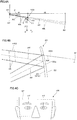
- Fig. 4A is a cross-sectional view illustrating an optical configuration of the head-up display device 100 and image formation by the device
- Fig. 4B is a cross-sectional view illustrating the display light HK reflected by the combiner 20.
- the display light HK reflected by the combiner 20 is guided to the pupil HT of the driver UN.
- a virtual image light beam KK which is an extension of the display light HK behind the combiner 20, forms a display image IM at a predetermined position ahead of the pupil HT of the driver UN.
- the distance d1 from the pupil HT to the combiner 20 is assumed to be in an extent of 0.5 to 1 m, for example, depending on the specification of the vehicle body 2, the distance d2 from the combiner 20 to the display image IM is assumed to be in an extent of 1 m or more, for example, and the angle of depression ⁇ looking down on the display image IM is assumed to be in an extent of 10° to 15°.
- the eye box SY illustrated in Fig. 4C is configured to cover the position of the pupil HT of the standard driver UN, with the size being 10 to 15 cm laterally and 5 to 8 cm longitudinally, for example.
- the first optical surface 21 provided at the pupil HT side of the combiner 20 projects, onto the pupil HT as the display image IM with little distortion, the image formed on the liquid crystal display panel 11 via the mirror 13. On this occasion, the first optical surface 21 is capable of forming the display image IM with no distortion due to its optical surface shape.
- the second optical surface 22 provided on the opposite side of the pupil HT of the combiner 20 partially reflects the display light HK transmitted through and diverted at the first optical surface 21.
- the display light reflected by the second optical surface 22 provided behind after divergence (referred to as secondary display light HK2 for convenience in the following) is transmitted through the first optical surface 21 to be incident on the pupil HT, and therefore may be possibly superimposed with the display image IM to form a double image.
- the secondary display light HK2 reflected by the second optical surface 22 travels as though having been emitted from a same point on the display image IM in relation with the original display light HK, the virtual image formed by the display light HK overlaps with the virtual image formed by the secondary display light HK2, whereby formation of a double image may be avoided.
- the curvature or inclination angle of the second optical surface 22 and the thickness of the main body layer 20a are adjusted on the basis of the first optical surface 21.
- the thickness of the main body layer 20a corresponding to the space between the second optical surface 22 and the first optical surface 21 becomes thinner from the center toward the periphery with regard to the lateral direction D2, as has been described referring to Figs.
- variation of the thickness of the main body layer 20a with regard to the vertical direction D1 turns out to be different between the central part and the peripheral part with regard to the lateral direction D2. Furthermore, the thickness of the main body layer 20a turns out to b thinner from the lower end toward the upper end in the vertical direction D1, at respective positions with regard to the lateral direction D2.
- the thickness of the main body layer 20a becomes thinner from the center toward the periphery with regard to the lateral direction D2 or the ⁇ direction, which is perpendicular to the reference plane SH1, and also the variation of the thickness of the main body layer 20a with regard to the vertical direction D1 or the ⁇ direction, which is parallel to the reference plane SH1, is different between the central part and the peripheral part with regard to the lateral direction D2, whereby it is possible to suppress formation of a double image more in respective parts of the center and the periphery, and to improve the image quality all over the eye box SY.
- the head-up display device 100 of the first embodiment includes the screen or the combiner 20 described above, whereby it is possible to suppress formation of a double image in respective parts of the center and the periphery, and to improve the image quality all over the eye box SY.
- the first and the second surfaces S1 and S2 following the 0-th surface S0 corresponding to the virtual image side are virtual surfaces, and the third side S3 corresponds to the pupil HT.
- each surface Si is specified by surface apex coordinates (x, y, z) and a rotation angle (ADE), respectively.
- the surface apex coordinates of each surface Si are expressed by coordinates (x, y, z) of the origin of a local Cartesian coordinate system (X, Y, Z) in a global Cartesian coordinate system (x, y, z), with the surface apex being the origin of the local Cartesian coordinate system (X, Y, Z) (unit in mm).
- the inclination of each surface Si is expressed by the ADE around the X-axis (X-rotation) or the rotation angle centered on the surface apex.
- the unit of rotation angle is assumed as "°" (degrees)
- the counterclockwise direction seen from the positive direction of an X-axis is assumed as the positive direction of the rotation angle of the X-rotation.
- the global Cartesian coordinate system (x, y, z) turns out to be an absolute coordinate system that coincides with the local Cartesian coordinate system (X, Y, Z) of the pupil HT or pupil surface (third surface S3).
- arrangement data of each surface Si is expressed by a global coordinate system with the pupil surface center being the origin.
- the direction from the pupil HT toward the combiner 20 is the +Z direction or the +z direction
- the upward direction relative to the pupil HT is the +Y direction or the +y direction
- the rightward direction relative to the pupil HT is the +X direction or the +x direction.
- the X-direction turns out to be parallel to the ⁇ direction illustrated in Fig. 4A
- the Y-direction turns out to be parallel to the ⁇ direction illustrated in Fig. 4A .
- the fourth surface S4 corresponding to the combiner 20 and the fifth surface S5 corresponding to the mirror 13 are free-form surfaces, and the free-form surface shape is expressed by the following "formula 1", with the apex of the surface being the origin, taking the Z axis in the optical axis direction, and X and Y denoting the heights in directions perpendicular to the optical axis:
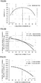
- Fig. 5A illustrates the thickness in the lateral cross section of the combiner 20 of the example 1
- Fig. 5B illustrates the thickness in the vertical cross section of the combiner 20 of the example 1.
- the combiner 20 of the example 1 has a relatively large curvature and a large enlargement rate.
- the lateral axis indicates the lateral coordinates and the vertical axis indicates the thickness of the combiner 20.
- the horizontal axis indicates vertical coordinates and the vertical axis indicates the relative thickness of the combiner 20.
- the curve illustrated as a dotted line indicates the variation of thickness in the vertical direction D1 at the periphery with regard to the lateral direction D2 of the combiner 20.
- the solid line indicates the variation of thickness in the central vertically-crossing zone 20i of the combiner 20 illustrated in Fig. 3A
- the dotted line indicates the variation of thickness in the peripheral parts 20j of the combiner 20 illustrated in Fig. 3A .
- the variation rate (absolute value) of the thickness in the vertical direction D1 is relatively larger in the +Y or the upper end 20r (see Fig. 3A ) corresponding to the other end than in the -Y or the lower end 20q (see Fig. 3A ) corresponding to one end.
- the difference between the variation rates of the thickness in the vertical direction D1 at both the upper and the lower ends is larger in the peripheral parts 20j and 20k indicated by the dotted line than in the central vertically-crossing zone 20i with regard to the lateral direction D2 indicated by the solid line.
- the thickness, at the lower end 20q corresponding to one end of the main body layer 20a based on the central laterally-crossing zone 20p passing through the center C1 of the vertical direction D1 and extending in the lateral direction D2, i.e., the amount of increase of thickness, is smaller by R1 in the peripheral part, i.e., the lateral-end lower region SH20 than in the central part with regard to the lateral direction D2, i.e., the central lower part SH10.
- the thickness in the vertical cross section of the combiner 20 of the comparative example 1 will be described.
- the variation of thickness (solid line) along the vertical direction D1 in the center with regard to the lateral direction D2 of the combiner 20 coincides with the variation of thickness (dotted line) along the vertical direction D1 in the periphery with regard to the lateral direction D2 of the combiner 20.
- Fig. 6A illustrates a lattice image displayed using the combiner 20 of the example 1 in a state being observed at the center of the eye box SY
- Fig. 6B illustrates a lattice image displayed using the combiner 20 of the example 1 in a state being observed at a diagonally upper part of the eye box SY.
- Fig. 6A it can be seen that formation of a double image is avoided in the image being observed at the center of the eye box SY, because the image formed by the dominant display light HK indicated by the solid line generally overlaps with the image formed by the secondary display light HK2 indicated by the dotted line.
- Fig. 6A illustrates a lattice image displayed using the combiner 20 of the example 1 in a state being observed at the center of the eye box SY
- Fig. 6B illustrates a lattice image displayed using the combiner 20 of the example 1 in a state being observed at a diagonally upper part of the eye box SY.
- Fig. 6C illustrates a lattice image displayed using the combiner 20 of the comparative example 1 in a state being observed at the center of the eye box SY
- Fig. 6D illustrates a lattice image displayed using the combiner 20 of the comparative example 1 in a state being observed a diagonally upper part of the eye box SY.
- Fig. 6C it can be seen that an outstanding double image has been formed in the image observed at the center of the eye box SY, because the image formed by the dominant display light HK indicated by the solid line is displaced as a whole in a blurred manner from the image formed by the secondary display light HK2 indicated by the dotted line.
- Fig. 6C illustrates a lattice image displayed using the combiner 20 of the comparative example 1 in a state being observed at the center of the eye box SY
- Fig. 6D illustrates a lattice image displayed using the combiner 20 of the comparative example 1 in a state being observed a diagonally upper part of the
- Fig. 7A illustrates the thickness in the lateral cross section of the combiner 20 of the example 2
- Fig. 7B illustrates the thickness in the vertical cross section of the combiner 20 of the example 2.
- the combiner 20 of the example 2 has a relatively small curvature and a small enlargement rate.
- the horizontal axis indicates the lateral coordinates and the vertical axis indicates the thickness of the combiner 20.
- Fig. 7B the horizontal axis indicates vertical coordinates and the vertical axis indicates the relative thickness of the combiner 20.
- the variation rate (absolute value) of the thickness in the vertical direction D1 is relatively larger in the +Y or the upper end 20r (see Fig. 3A ) corresponding to the other end than in the -Y or the lower end 20q (see Fig. 3A ) corresponding to one end.
- the difference between the variation rates of the thickness in the vertical direction D1 at the upper and the lower ends is larger in the peripheral parts 20j and 20k indicated by the dotted line than in the central vertically-crossing zone 20i with regard to the lateral direction D2 indicated by the solid line.
- the thickness at the lower end 20q corresponding to one end of the main body layer 20a based on the central laterally-crossing zone 20p passing through the center C1 and extending in the lateral direction D2, i.e., the amount of increase of thickness is smaller by R1 in the peripheral part, i.e., the lateral-end lower region SH20 than in the central part with regard to the lateral direction D2, i.e., the central lower part SH10.
- the thickness in the vertical cross section of the combiner 20 of the comparative example 2 will be described.
- the variation of thickness (solid line) along the vertical direction D1 in the center with regard to the lateral direction D2 of the combiner 20 coincides with the variation of thickness (dotted line) along the vertical direction D1 in the periphery with regard to the lateral direction D2 of the combiner 20.
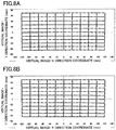
- Fig. 8A illustrates a lattice image displayed using the combiner 20 of the example 2 in a state being observed at the center of the eye box SY
- Fig. 8B illustrates a lattice image displayed using the combiner 20 of the example 2 in a state being observed at a diagonally upper part of the eye box SY.
- Fig. 8A it can be seen that formation of a double image is avoided in the image being observed at the center of the eye box SY, because the image formed by the dominant display light HK indicated by the solid line generally overlaps with the image formed by the secondary display light HK2 indicated by the dotted line.
- Fig. 8A illustrates a lattice image displayed using the combiner 20 of the example 2 in a state being observed at the center of the eye box SY
- Fig. 8B illustrates a lattice image displayed using the combiner 20 of the example 2 in a state being observed at a diagonally upper part of the eye box SY.
- a screen and a head-up display device having incorporated therein according to a second embodiment will be described.
- the screen or the like of the second embodiment is a modification of the screen or the like of the first embodiment and items which are not described in particular are similar to those of the first embodiment.
- the windshield 8 has a thin intermediate layer 120 embedded therein, and a rectangular reflection region 8d provided on the windshield 8 facing the driving seat functions as the screen.
- the screen of the present embodiment turns out to be the windshield 8 having provided thereon the reflection region 8d, which is the virtual image display region reflecting the display light HK.
- the thickness of the intermediate layer 120 increases toward the upper part in a wedge-like manner.
- the inner surface of the windshield 8 functions as the first optical surface 21, and the inner surface of the intermediate layer 120 functions as the second optical surface 22.
- the shape of the first optical surface 21 may be adjusted to a certain extent by fabricating or processing the inner surface of the windshield 8, the range of adjustment is narrow.
- the shape of the second optical surface 22 may be adjusted by adjusting the arrangement or thickness of the intermediate layer 120.
- adjusting the space or inclination of the second optical surface 22 relative to the first optical surface 21 as appropriate allows for forming a small angle against the virtual image light beam KK which is an extended line of the display light HK reflected by the first optical surface 21, as well as causing the secondary display light HK2 to extend along the extended line of another virtual image light beam KK2 emitted from the same virtual image point. Accordingly, it is possible to avoid formation of a double image due to overlapping with a slight displacement of the virtual image formed by the display light HK and the virtual image formed by the secondary display light HK2.
- the thickness of the main body layer 20a between the first optical surface 21 and the second optical surface 22 becomes thinner from the center toward the periphery with regard to the lateral direction D2.
- the thickness of the main body layer 20a becomes thinner from one end at the lower side toward the other end at the upper side corresponding to the direction in which the display light HK is diagonally incident with regard to the vertical direction D1.
- the variation of the thickness of the main body layer 20a with regard to the vertical direction D1 at the center of the lateral direction D2 is different from the variation of the thickness of the main body layer 20a with regard to the vertical direction D1 in the peripheral of the lateral direction D2.
- a screen and a head-up display device having incorporated therein according to a third embodiment will be described.
- the screen or the like of the third embodiment is a modification of the screen or the like of the first and the second embodiments and items which are not described in particular are similar to those of the first embodiment or the like.
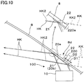
- the windshield 8 has a combiner part 220 adhered, as the screen, inside the rectangular reflection region 8d provided on the windshield 8 facing the driving seat.
- the screen of the present embodiment turns out to be the windshield 8 having provided thereon the reflection region 8d, which is the virtual image display region reflecting the display light HK.
- the inner surface of the combiner part 220 functions as the first optical surface 21
- the outer surface of the windshield 8 functions as the second optical surface 22.
- adjusting the space or inclination of the second optical surface 22 relative to the first optical surface 21 as appropriate allows for forming a small angle against the virtual image light beam KK which is an extension of the display light HK reflected by the first optical surface 21, as well as causing the secondary display light HK2 to extend along the extended line of another virtual image light beam KK2 emitted from the same virtual image point. Accordingly, it is possible to avoid formation of a double image due to overlapping with a slight displacement of the virtual image formed by the display light HK and the virtual image formed by the secondary display light HK2.
- the thickness of the composite main body layer 220a between the first optical surface 21 and the second optical surface 22 becomes thinner from the center toward the periphery with regard to the lateral direction D2.
- the thickness of the main body layer 220a becomes thinner from one end at the lower side toward the other end at the upper side corresponding to the direction in which the display light HK is diagonally incident with regard to the vertical direction D1.
- the variation of the thickness of the main body layer 220a with regard to the vertical direction D1 at the center of the lateral direction D2 is different from the variation of the thickness of the main body layer 220a with regard to the vertical direction D1 in the peripheral of the lateral direction D2.
- the screen or the like according to embodiments has been described above, the screen or the like according to the present invention is not limited thereto.
- the arrangement of the head-up display device 100 may be turned upside down so that the combiner 20 may be provided on the upper part of the windshield 8 or at the sun visor position, in which case the combiner 20 is provided diagonally downward ahead of the drawing unit 10.
- the outline of the combiner 20 and the outline of the reflection region 8d is not limited to be rectangular, and may have various shapes.
- the drawing unit 10 illustrated in Fig. 2 is merely exemplary, in which the mirror 13 may be omitted, or the liquid crystal display panel 11 may be replaced by other types of display elements.
Landscapes
- Engineering & Computer Science (AREA)
- Physics & Mathematics (AREA)
- General Physics & Mathematics (AREA)
- Chemical & Material Sciences (AREA)
- Combustion & Propulsion (AREA)
- Transportation (AREA)
- Mechanical Engineering (AREA)
- Optics & Photonics (AREA)
- Instrument Panels (AREA)
- Fittings On The Vehicle Exterior For Carrying Loads, And Devices For Holding Or Mounting Articles (AREA)
Abstract
Description
- The present invention relates to a screen for displaying an image at the end of the line of sight and a head-up display device having incorporated therein.
- A head-up display device is capable of displaying information in a manner overlapped with the background at the end of the line of sight. Incorporating such a head-up display device, for example, in an automobile allows for projecting, at the end of the line of sight such as a windshield, an image including information such as speed obtained by instruments in the vehicle while driving the automobile, which facilitates driving without changing the eyesight and may lead to accident prevention.
- There is known a type of head-up display device including, for example, a combiner adhered inside a windshield, with the vertical cross section of the combiner being wedge-shaped and made relatively thinner at the lower part where a visual display device is located so as to prevent formation of a double image (Patent Literature 1).
- There is known a type of head-up display device including, for example, a combiner provided in an upright manner on the inside of a windshield in a manner separated from the windshield, with the radius of curvature being smaller at the observer's side (Patent Literature2).
- However, the combiner according to
Patent Literatures 1 and 2, has not sufficiently taken into consideration of the thickness of the lateral section and, even when the double image of the image in the vertical direction at the central part with regard to the lateral direction is dissolved, the double image in the periphery with regard to the lateral direction is not sufficiently dissolved, thereby resulting in degradation of the image quality as a whole. Particularly, significant degradation of the image quality occurs in the case with a wide viewing angle and a wide eye box. -
- Patent Literature1: Japanese Patent Laid-Open No.
2012-58688 - Patent Literature2: Japanese Patent Laid-Open No.
2014-115417 - It is an object of the present invention, which has been made in view of the aforementioned background, to provide a screen capable of preventing generation of a double image also a lateral direction, and improving the image quality as a whole, and a head-up display device having incorporated therein.
- To solve the aforementioned problem, a screen for a head-up display device that reflects an aspect of the present invention has a main body layer sandwiched between a first concave optical surface located at an observation side and a second convex optical surface located at a side opposite to the observation side, wherein the thickness of the main body layer becomes thinner from the center toward the periphery with regard to a lateral direction which is perpendicular to a reference plane, and variation of the thickness of the main body layer with regard to a vertical direction parallel to the reference plane is different between the central part and the peripheral part with regard to the lateral direction. Note that the reference plane is a plane including an optical axis, and becomes a vertical plane when display light is incident from an upward or downward direction. In addition, the thickness of the main body layer relates to the direction parallel to the normal direction of the first optical surface at the center. Furthermore, the lateral direction is not limited to the horizontal direction.
- To solve the aforementioned problem, the head-up display device reflecting an aspect of the present invention includes the aforementioned screen and a drawing unit that projects display light on the screen.
-
-
Fig. 1A is a side cross-sectional view illustrating a combiner, which is a screen of a first embodiment, and a head-up display device having incorporated therein, in a state being mounted on a vehicle body, andFig. 1B is a front view illustrating the combiner or the like seen from the inside of the car; -
Fig. 2 is an enlarged side cross-sectional view illustrating the head-up display device inFig. 1A ; -
Fig. 3A is a front view of the combiner,Fig. 3B is a cross-sectional view seen from arrow AA of the combiner illustrated inFig. 3A, and Fig. 3C is a cross-sectional view seen from arrow BB of the combiner illustrated inFig. 3A ; -
Fig. 4A is a cross-sectional view illustrating image formation by the head-up display device,Fig. 4B is an enlarged view illustrating display light reflected by the combiner, andFig. 4C is a diagram illustrating an eye box capable of observing a virtual image; -
Fig. 5A is a chart illustrating the thickness distribution in the lateral direction along a central lateral cross section of the combiner in a first example,Fig. 5B is a chart illustrating the thickness distribution in the vertical direction of the combiner of the first example, andFig. 5C is a chart illustrating the thickness distribution in the vertical direction of the combiner of a first comparative example; -
Fig. 6A illustrates a lattice image displayed using the combiner of the first example in a state being observed at the center of the eye box,Fig. 6B illustrates the lattice image displayed using the combiner of the first example in a state being observed at a diagonally upper part of the eye box,Fig. 6C illustrates the lattice image of the first comparative example in a state being observed at the center of the eye box, andFig. 6D illustrates the lattice image of the first comparative example in a state being observed at a diagonally upper part of the eye box; -
Fig. 7A is a chart illustrating the thickness distribution in the lateral direction along the central lateral cross section of a combiner in a second example,Fig. 7B is a chart illustrating the thickness distribution in the vertical direction of the combiner of the second example, andFig. 7C is a chart illustrating the thickness distribution in the vertical direction of the combiner of the second comparative example; -
Fig. 8A illustrates a lattice image of the second example in a state being observed at the center of the eye box, andFig. 8B illustrates a lattice image of the second example in a state being observed at a diagonally upper part of the eye box; -
Fig. 9A is a front view seen from the inside of the car and illustrating a windshields or the like, which is a screen of a second embodiment, andFig. 9B is a side cross-sectional view illustrating the head-up display device; and -
Fig. 10 is a side cross-sectional view illustrating a windshield or the like, which is a screen of a third embodiment. - In the following, a screen and a head-up display device having incorporated therein according to a first embodiment of the present invention will be described.
-
Figs. 1A and 1B are a conceptual side cross-sectional view and a front view illustrating a head-updisplay device 100 of the present embodiment and its usage state. The head-updisplay device 100, which is intended to be mounted on in avehicle body 2, includes adrawing unit 10 and acombiner 20. - The
drawing unit 10, which is provided so as to be embedded in adashboard 4 of thevehicle body 2, emits display light HK corresponding to an image including driving-related information toward thecombiner 20. Thecombiner 20, which is a screen that functions as a semi-transparent concave mirror and provided in an upright manner on thedashboard 4 in a manner supported by a lower part end, reflects the display light HK from thedrawing unit 10 to the backward of thevehicle body 2. In other words, thecombiner 20 turns out to be a stand-alone type provided separately from awindshield 8. The display light HK reflected by the combiner (screen) 20 is guided to an eye box corresponding to a pupil HT and its peripheral position of a driver UN. The driver UN is allowed to observe the display light HK reflected by thecombiner 20, i.e., a display image IM as a virtual image located ahead of thevehicle body 2. On the other hand, the driver UN is allowed to observe outside light transmitted through thecombiner 20, i.e., a real image such as a scenery ahead. As a result, the driver UN is allowed to observe the display image (virtual image) IM including driving-related information formed by reflection of the display light HK by thecombiner 20, in a manner overlapped with an outside image behind thecombiner 20. -
Fig. 2 is a cross-sectional view illustrating an enlarged view of the head-updisplay device 100. Of the components included in the head-updisplay device 100, thedrawing unit 10 has adrawing device 12 including liquidcrystal display panel 11, amirror 13, and ahousing 14. Thedrawing device 12 has, besides the liquidcrystal display panel 11, a display driving circuit that causes the liquidcrystal display panel 11 to perform a display operation, a light source such as LED or the like that emits light for illuminating the liquidcrystal display panel 11, and an optical equalization system or the like to that equalizes light from such a light source, although detailed description thereof being omitted. Themirror 13 may be convex, concave, or planar and, in the case of a curved surface, may be an aspheric surface, a free-form surface, or the like, without being limited to a spherical surface. Thehousing 14 has anaperture 14a that allows transmission of the display light HK therethrough, and theaperture 14a may have a film- or thin-sheetlight transmission member 15 provided thereon. - The
combiner 20, which is a plate-like member, has a firstoptical surface 21 provided at the observing side or a seat 6 (seeFig. 1A ) side where the driver UN is sitting as the observer, and a secondoptical surface 22 provided at a side opposite to the observation side or at a side of thewindshield 8. The firstoptical surface 21, being a concave curved surface, turns out to be an aspheric surface or a free-form surface. The secondoptical surface 22, being a convex curved surface (a concave curved surface when seen from the observer side), turns out to be an aspheric surface or a free-form surface. The firstoptical surface 21 has been obtained by forming a half-mirror coating 20b having a reflectivity of 20 to 30%, for example, on amain body layer 20a, which is a base member, and allows for transmitting outside light GK therethrough to a desired degree while reflecting the display light HK as appropriate. The secondoptical surface 22 turns out to have themain body layer 20a exposed therefrom without forming anti-reflection film (or anti-reflection coating). In such a case, it is possible to suppress formation of a double image while reducing cost by omitting the anti-reflection coating. However, the secondoptical surface 22 may also have anti-reflection film formed thereon, or may be covered with protection coating. -
Figs. 3A to 3C are a front view of the combiner (screen) 20, a cross-sectional view seen from arrow AA, and a cross-sectional view seen from arrow BB. Thecombiner 20 is divided laterally into two parts by a virtual reference plane SH1 including an optical axis AX passing through a center C1, and a laterally symmetrical in shape. Thecombiner 20, although divided vertically into two parts by a virtual intersecting surface SH2 passing through the center C1 and extending horizontally, is not vertically symmetrical in shape. Here, the intersecting surface SH2 is a surface perpendicular to the reference plane SH1 and passing through the center C1, and is also a surface parallel to the α - γ surface. Note that, in the present specification, the optical axis AX is considered on the basis of the display light HK passing through the center C1 of thecombiner 20 and guided to the center of an eye box SY (seeFig. 4C ). In addition, thecombiner 20 in the drawing illustrates only an optically effective region, and may have aframe part 20z around the effective region. In other words, the center C1 of thecombiner 20 is the optical center and does not necessarily coincide with the center of contour. - Of the components included in the
combiner 20, a central vertically-crossing zone 20i, which is a central part with regard to the lateral direction D2, is a part where thecombiner 20 intersects with the reference plane SH1 or the vertical plane passing through the center C1. The central vertically-crossing zone 20i, which is curved as a whole in the longitudinal direction, extends in a vertical direction D1 inclined against the vertical β-axis direction. In addition, a pair ofperipheral parts - Of the components of the
combiner 20, a central laterally-crossing zone 20p, which is the central part with regard to the vertical direction D1, is a part where thecombiner 20 intersects with the intersecting surface SH2, is curved as a whole in the longitudinal direction. A pair of upper and lowervertical ends crossing zone 20p extend in the lateral direction D2 in parallel to the central laterally-crossing zone 20p, both being curved as a whole in the longitudinal direction. - Although a virtual image is displayed by reflection on the first
optical surface 21, a secondary virtual image is also formed by reflection on the secondoptical surface 22, and therefore thecombiner 20 causes the subsidiary virtual image to overlap with the original virtual image in terms of size and position to prevent formation of a double image due to the subsidiary virtual image. In other words, the size and position of the virtual image formed on one hand by the display light HK reflected by the firstoptical surface 21 are caused to coincide with the size and position of the virtual image formed on the other hand by the display light HK2 transmitted through the firstoptical surface 21 and reflected by the secondoptical surface 22. In other words, it turns out that the display light HK emitted from the same display point and reflected by the firstoptical surface 21, and the display light HK2 transmitted through the firstoptical surface 21 and reflected by the secondoptical surface 22 are guided to the eye box SY side as though having been emitted from a same virtual image point corresponding to the display point. That is, the display lights HK and HK2 emitted from thedrawing unit 10 toward different directions are guided as though having been emitted from the same virtual image point. As a result, the cross-sectional shape of thecombiner 20 has the following characteristics. - First, the thickness of the
main body layer 20a in thecombiner 20 turns out to become thinner from the center toward the periphery with regard to the lateral direction D2. Specifically, in the central laterally-crossing zone 20p extending in the lateral direction D2 at the center of the vertical direction D1, for example, the thickness of themain body layer 20a, which is thickest at the center C1, gradually becomes thinner toward a lateral-end region SH21, and turns out to be thinnest at the lateral-end region SH21. Similarly to the central laterally-crossing zone 20p, the upper and lowervertical ends main body layer 20a is considered in a direction parallel to the normal NL direction (seeFig. 3B ) of the firstoptical surface 21 at the center C1. - In addition, the thickness of
main body layer 20a in thecombiner 20 becomes thinner from one end at the lower side toward the other end at the upper side corresponding to the direction in which the display light HK is diagonally incident with regard to the vertical direction D1. Accordingly, it is possible to suppress formation of a double image in respective parts in the vertical direction D1. Specifically, in the central vertically-crossing zone 20i extending in the vertical direction D1 at the center of the lateral direction D2, for example, the thickness of themain body layer 20a, which is thickest at the central lower part SH10, gradually becomes thinner toward the center C1 and the central upper part SH12, and turns out to be thinnest at the central upper part SH12. Similarly to the central vertically-crossing zone 20i, theperipheral parts - Furthermore, variation of the thickness of the
main body layer 20a with regard to the vertical direction D1 in the central vertically-crossing zone 20i is different from the variation of the thickness of themain body layer 20a with regard to the vertical direction D1 in theperipheral parts -
Fig. 4A is a cross-sectional view illustrating an optical configuration of the head-updisplay device 100 and image formation by the device, andFig. 4B is a cross-sectional view illustrating the display light HK reflected by thecombiner 20. As illustrated in the drawings, the display light HK reflected by thecombiner 20 is guided to the pupil HT of the driver UN. Here, a virtual image light beam KK, which is an extension of the display light HK behind thecombiner 20, forms a display image IM at a predetermined position ahead of the pupil HT of the driver UN. Note that the distance d1 from the pupil HT to thecombiner 20 is assumed to be in an extent of 0.5 to 1 m, for example, depending on the specification of thevehicle body 2, the distance d2 from thecombiner 20 to the display image IM is assumed to be in an extent of 1 m or more, for example, and the angle of depression θ looking down on the display image IM is assumed to be in an extent of 10° to 15°. In addition, the eye box SY illustrated inFig. 4C is configured to cover the position of the pupil HT of the standard driver UN, with the size being 10 to 15 cm laterally and 5 to 8 cm longitudinally, for example. - The first
optical surface 21 provided at the pupil HT side of thecombiner 20 projects, onto the pupil HT as the display image IM with little distortion, the image formed on the liquidcrystal display panel 11 via themirror 13. On this occasion, the firstoptical surface 21 is capable of forming the display image IM with no distortion due to its optical surface shape. On the other hand, the secondoptical surface 22 provided on the opposite side of the pupil HT of thecombiner 20 partially reflects the display light HK transmitted through and diverted at the firstoptical surface 21. The display light reflected by the secondoptical surface 22 provided behind after divergence (referred to as secondary display light HK2 for convenience in the following) is transmitted through the firstoptical surface 21 to be incident on the pupil HT, and therefore may be possibly superimposed with the display image IM to form a double image. However, when the secondary display light HK2 reflected by the secondoptical surface 22 travels as though having been emitted from a same point on the display image IM in relation with the original display light HK, the virtual image formed by the display light HK overlaps with the virtual image formed by the secondary display light HK2, whereby formation of a double image may be avoided. In other words, as conceptually illustrated inFig. 4B , it suffices to cause the display light HK to extend along the extended line of the original virtual image light beam KK, and cause the secondary display light HK2 to extend along the extended line of the other virtual image light beam KK2 forming a small angle against the original virtual image light beam KK. On this occasion, it suffices to consider the relation between the display light HK and the secondary display light HK2 in such a range that both are simultaneously incident on the pupil HT of the driver UN. To control the direction of travel of the secondary display light HK2 in the aforementioned manner, the curvature or inclination angle of the secondoptical surface 22 and the thickness of themain body layer 20a are adjusted on the basis of the firstoptical surface 21. As a result, the thickness of themain body layer 20a corresponding to the space between the secondoptical surface 22 and the firstoptical surface 21 becomes thinner from the center toward the periphery with regard to the lateral direction D2, as has been described referring toFigs. 3A to 3C , and variation of the thickness of themain body layer 20a with regard to the vertical direction D1 turns out to be different between the central part and the peripheral part with regard to the lateral direction D2. Furthermore, the thickness of themain body layer 20a turns out to b thinner from the lower end toward the upper end in the vertical direction D1, at respective positions with regard to the lateral direction D2. - According to the screen or the combiner of the
first embodiment 20 described above, the thickness of themain body layer 20a becomes thinner from the center toward the periphery with regard to the lateral direction D2 or the α direction, which is perpendicular to the reference plane SH1, and also the variation of the thickness of themain body layer 20a with regard to the vertical direction D1 or the β direction, which is parallel to the reference plane SH1, is different between the central part and the peripheral part with regard to the lateral direction D2, whereby it is possible to suppress formation of a double image more in respective parts of the center and the periphery, and to improve the image quality all over the eye box SY. - In addition, the head-up
display device 100 of the first embodiment includes the screen or thecombiner 20 described above, whereby it is possible to suppress formation of a double image in respective parts of the center and the periphery, and to improve the image quality all over the eye box SY. - In the following, specific examples of the head-up display device according to the present invention will be described.
- In the data of the example described below, Si (i=0, 1, 2, 3, ...) indicates the i-th surface counted from the virtual image side forming the display image IM (the virtual image side of the display image IM being the 0-th surface). The first and the second surfaces S1 and S2 following the 0-th surface S0 corresponding to the virtual image side are virtual surfaces, and the third side S3 corresponds to the pupil HT.
- The arrangement of each surface Si is specified by surface apex coordinates (x, y, z) and a rotation angle (ADE), respectively. The surface apex coordinates of each surface Si are expressed by coordinates (x, y, z) of the origin of a local Cartesian coordinate system (X, Y, Z) in a global Cartesian coordinate system (x, y, z), with the surface apex being the origin of the local Cartesian coordinate system (X, Y, Z) (unit in mm). In addition, the inclination of each surface Si is expressed by the ADE around the X-axis (X-rotation) or the rotation angle centered on the surface apex. Note that the unit of rotation angle is assumed as "°" (degrees), and the counterclockwise direction seen from the positive direction of an X-axis is assumed as the positive direction of the rotation angle of the X-rotation. In addition, the global Cartesian coordinate system (x, y, z) turns out to be an absolute coordinate system that coincides with the local Cartesian coordinate system (X, Y, Z) of the pupil HT or pupil surface (third surface S3). In other words, arrangement data of each surface Si is expressed by a global coordinate system with the pupil surface center being the origin. Note that, in the pupil surface (third surface S3), the direction from the pupil HT toward the
combiner 20 is the +Z direction or the +z direction, the upward direction relative to the pupil HT is the +Y direction or the +y direction, and the rightward direction relative to the pupil HT is the +X direction or the +x direction. In other words, the X-direction turns out to be parallel to the α direction illustrated inFig. 4A , and the Y-direction turns out to be parallel to the β direction illustrated inFig. 4A . - In respective examples, the fourth surface S4 corresponding to the
combiner 20 and the fifth surface S5 corresponding to themirror 13 are free-form surfaces, and the free-form surface shape is expressed by the following "formula 1", with the apex of the surface being the origin, taking the Z axis in the optical axis direction, and X and Y denoting the heights in directions perpendicular to the optical axis:
- c: apex curvature (c =1/R)
- k: conic constant
- Cj: coefficient of XmYn
- R: Y radius of curvature
- In the following, specific examples of the head-up display device of the present invention will be described.
- Basic specifications of the head-up display device of an example 1 are listed in the following table 1.
[Table 1] reference wavelength 520nm eye box size X direction:-50mm∼+50mm×Y direction : -14mm ∼+11mm LCD size X direction: 39.8mm × Y direction: 22.4mm - Data of the optical surface or the like of the example 1 are listed in the following table 2.
[Table 2] surface number corresponding item radius of cuevature space between surfaces arrangement and coordinates of surface x y z ADE cartesian coordinate system reference surface number S0 (object) virtual image ∞ -2538.567 local S1 ∞ 0 10.000 local S2 ∞ 0 0.000 0.000 0.000 0.000 local S3 diaphragm surface (φ 5mm) ∞ 0 0.000 0.000 0.000 -10.000 global S2 S4 combiner (first optical surface) see table below 0.000 -141.060 800.000 10.000 global S2 S5 mirror see table below 0.000 -230.000 646.255 0.002 global S2 S6 (image surface) LCD ∞ 0.000 -287.304 745.690 0.000 global S2 - Surface data of the combiner part of the example 1 are listed in the following table 3. The "*" in the table expresses the product, and the "^" expresses the exponential (the same goes for the following examples). Note that the space between a pair of surfaces forming the combiner is 3.0 mm, the material of the combiner is polycarbonate (nd =1.5869, vd =30.0), and the optical surface size is 148 mm in the X-direction, and 68 mm in the Y-direction.
[Table 3] Cj first surface (concave surface) second surface (convex surface) Y radius of cuevature R -4.099274E+02 -4.115342E+02 conic constant C1 -1.800271E-01 -5.858534E-01 X C2 0.000000E+00 0.000000E+00 Y C3 0.000000E+00 5.936875E-04 X^2 C4 4.868318E-04 4.855998E-04 X*Y C5 0.000000E+00 0.000000E+00 Y^2 C6 6.279177E-04 6.272233E-04 X^3 C7 0.000000E+00 0.000000E+00 X^2*Y C8 6.070492E-07 6.432424E-07 X*Y^2 C9 0.000000E+00 0.000000E+00 Y^3 C10 1.001214E-06 1.059070E-06 X^4 C11 1.817088E-09 1.817088E-09 X^3*Y C12 0.000000E+00 0.000000E+00 X^2*Y^2 C13 4.272311E-09 4.272311 E-09 X*Y^3 C14 0.000000E+00 0.000000E+00 Y^4 C15 3.863658E-09 3.863658E-09 X^5 C16 0.000000E+00 0.000000E+00 X^4*Y C17 -8.761324E-12 -8.761324E-12 X^3*Y^2 C18 0.000000E+00 0.000000E+00 X^2*Y^3 C19 2.004210E-11 2.004210E-11 X*Y^4 C20 0.000000E+00 0.000000E+00 Y^5 C21 6.310483E-12 6.310483E-12 - The surface data of the mirror part of the example 1 are listed in the following table 4.
[Table 4] Cj reflection surface Y radius of cuevature R 9.500313E+02 conic constant C1 -3.205652E+01 X C2 0.000000E+00 Y C3 0.000000E+00 X^2 C4 -4.110722E-04 X*Y C5 0.000000E+00 Y^2 C6 -1.072301E-04 X^3 C7 0.000000E+00 X^2*Y C8 3.191371E-06 X*Y^2 C9 0.000000E+00 Y^3 C10 4.406605E-06 X^4 C11 1.308794E-08 X^3*Y C12 0.000000E+00 X^2*Y^2 C13 8.932960E-10 X*Y^3 C14 0.000000E+00 Y^4 C15 -6.389405E-09 X^5 C16 0.000000E+00 X^4*Y C17 -2.825664E-10 X^3*Y^2 C18 0.000000E+00 X^2*Y^3 C19 1.226848E-10 X*Y^4 C20 0.000000E+00 Y^5 C21 -9.147205E-11 -
Fig. 5A illustrates the thickness in the lateral cross section of thecombiner 20 of the example 1 andFig. 5B illustrates the thickness in the vertical cross section of thecombiner 20 of the example 1. Thecombiner 20 of the example 1 has a relatively large curvature and a large enlargement rate. In the chart ofFig. 5A , the lateral axis indicates the lateral coordinates and the vertical axis indicates the thickness of thecombiner 20. Additionally, inFig. 5B , the horizontal axis indicates vertical coordinates and the vertical axis indicates the relative thickness of thecombiner 20. The curve illustrated as a solid line inFig. 5B indicates the variation of thickness in the vertical direction D1 at the center with regard to the lateral direction D2 of thecombiner 20, and the curve illustrated as a dotted line indicates the variation of thickness in the vertical direction D1 at the periphery with regard to the lateral direction D2 of thecombiner 20. Specifically, the solid line indicates the variation of thickness in the central vertically-crossing zone 20i of thecombiner 20 illustrated inFig. 3A , and the dotted line indicates the variation of thickness in theperipheral parts 20j of thecombiner 20 illustrated inFig. 3A . As can be clearly seen inFig. 5B , with regard to the thickness of themain body layer 20a of thecombiner 20, the variation rate (absolute value) of the thickness in the vertical direction D1 is relatively larger in the +Y or theupper end 20r (seeFig. 3A ) corresponding to the other end than in the -Y or thelower end 20q (seeFig. 3A ) corresponding to one end. In addition, with regard to the thickness in the vertical direction D1 of themain body layer 20a of thecombiner 20, the difference between the variation rates of the thickness in the vertical direction D1 at both the upper and the lower ends is larger in theperipheral parts lower end 20q corresponding to one end of themain body layer 20a based on the central laterally-crossing zone 20p passing through the center C1 of the vertical direction D1 and extending in the lateral direction D2, i.e., the amount of increase of thickness, is smaller by R1 in the peripheral part, i.e., the lateral-end lower region SH20 than in the central part with regard to the lateral direction D2, i.e., the central lower part SH10. - Referring to
Fig. 5C , the thickness in the vertical cross section of thecombiner 20 of the comparative example 1 will be described. In such a case, the variation of thickness (solid line) along the vertical direction D1 in the center with regard to the lateral direction D2 of thecombiner 20 coincides with the variation of thickness (dotted line) along the vertical direction D1 in the periphery with regard to the lateral direction D2 of thecombiner 20. -
Fig. 6A illustrates a lattice image displayed using thecombiner 20 of the example 1 in a state being observed at the center of the eye box SY, andFig. 6B illustrates a lattice image displayed using thecombiner 20 of the example 1 in a state being observed at a diagonally upper part of the eye box SY. As illustrated inFig. 6A , it can be seen that formation of a double image is avoided in the image being observed at the center of the eye box SY, because the image formed by the dominant display light HK indicated by the solid line generally overlaps with the image formed by the secondary display light HK2 indicated by the dotted line. In addition, as illustrated inFig. 6B , it can also be seen that formation of a double image is avoided in the image being observed at a corner of the eye box SY, because the image formed by the dominant display light HK indicated by the solid line generally overlaps with the image formed by the secondary display light HK2 indicated by the dotted line. -
Fig. 6C illustrates a lattice image displayed using thecombiner 20 of the comparative example 1 in a state being observed at the center of the eye box SY, andFig. 6D illustrates a lattice image displayed using thecombiner 20 of the comparative example 1 in a state being observed a diagonally upper part of the eye box SY. As illustrated inFig. 6C , it can be seen that an outstanding double image has been formed in the image observed at the center of the eye box SY, because the image formed by the dominant display light HK indicated by the solid line is displaced as a whole in a blurred manner from the image formed by the secondary display light HK2 indicated by the dotted line. In addition, as illustrated inFig. 6D , it can also be seen that an outstanding double image has been formed in the image observed at a corner of the eye box SY, because the image formed by the dominant display light HK indicated by the solid lines displaced as a whole in a blurred manner from the image formed by the secondary display light HK2 indicated by the dotted line. - Basic specifications of the head-up display device of an example 2 are listed in the following table 5.
[Table 5] reference wavelength 520nm eye box size X direction:-50mm∼+50mm× Y direction:-15mm∼+15mm LCD size X direction:39.8mm× Y direction: 22.4mm - Data of the optical surface or the like of the example 2 are listed in the following table 6.
[Table 6] surface number corresponding item radius of cuevature space between surfaces arrangement and coordinates of surface x y z ADE cartesian coordinate system reference surface number S0 (object) virtual image ∞ -2538.567 local S1 ∞ 0 10.000 local S2 ∞ 0 0.000 0.000 0.000 0.000 local S3 diaphragm surface (φ 5mm) ∞ 0 0.000 0.000 0.000 -10.000 global S2 S4 combiner (first optical surface) see table below 0.000 -141.060 800.000 10.000 global S2 S5 mirror see table below 0.000 -206.400 690.000 3.120 global S2 S6 (image surface) LCD ∞ 0.000 -252.000 795.411 0.000 global S2 - Surface data of the combiner part of the example 2 are listed in the following table 7. Note that the space between a pair of surfaces forming the combiner is 3.0 mm, the material of the combiner is polycarbonate (nd =1.5869, vd =30.0), and the optical surface size is 148 mm in the X-direction, and 73 mm in the Y-direction.
[Table 7] Cj first surface (concave surface) second surface (convex surface) Yradius of cuevature R ∞ ∞ conic constant C1 0.000000E+00 0.000000E+00 X C2 0.000000E+00 0.000000E+00 Y C3 0.000000E+00 9.217458E-04 X^2 C4 -1.084093E-03 -1.075852E-03 X*Y C5 0.000000E+00 0.000000E+00 Y^2 C6 -9.007398E-04 -8.967213E-04 X^3 C7 0.000000E+00 0.000000E+00 X^2*Y C8 7.552202E-07 7.417251 E-07 X*Y^2 C9 0.000000E+00 0.000000E+00 Y^3 C10 1.514743E-06 1.482545E-06 X^4 C11 -2.394723E-10 -2.394723E-10 X^3*Y C12 0.000000E+00 0.000000E+00 X^2*Y^2 C13 -4.628489E-10 -4.628489E-10 X*Y^3 C14 0.000000E+00 0.000000E+00 Y^4 C15 -1.767370E-11 -1.767370E-11 X^5 C16 0.000000E+00 0.000000E+00 X^4*Y C17 -1.761966E-11 -1.761966E-11 X^3*Y^2 C18 0.000000E+00 0.000000E+00 X^2*Y^3 C19 4.162014E-11 4.162014E-11 X*Y^4 C20 0.000000E+00 0.000000E+00 Y^5 C21 -1.432843E-12 -1.432843E-12 - The surface data of the mirror part of the example 2 are listed in the following table 8.
[Table 8] Cj reflection surface Y radius of cuevature R 2.200309E+03 conic constant C1 4.820375E+01 X C2 0.000000E+00 Y C3 0.000000E+00 X^2 C4 -1.032779E-03 X*Y C5 0.000000E+00 Y^2 C6 -5.767935E-04 X^3 C7 0.000000E+00 X^2*Y C8 4.181558E-06 X*Y^2 C9 0.000000E+00 Y^3 C10 9.424649E-06 X^4 C11 1.534243E-08 X^3*Y C12 0.000000E+00 X^2*Y^2 C13 -1.059661E-08 X*Y^3 C14 0.000000E+00 Y^4 C15 -4.522601 E-08 X^5 C16 0.000000E+00 X^4*Y C17 -6.555304E-10 X^3*Y^2 C18 0.000000E+00 X^2*Y^3 C19 8.533320E-10 X*Y^4 C20 0.000000E+00 Y^5 C21 -1.774170E-10 -
Fig. 7A illustrates the thickness in the lateral cross section of thecombiner 20 of the example 2 andFig. 7B illustrates the thickness in the vertical cross section of thecombiner 20 of the example 2. Thecombiner 20 of the example 2 has a relatively small curvature and a small enlargement rate. In the chart ofFig. 7A , the horizontal axis indicates the lateral coordinates and the vertical axis indicates the thickness of thecombiner 20. Additionally, inFig. 7B , the horizontal axis indicates vertical coordinates and the vertical axis indicates the relative thickness of thecombiner 20. The curve illustrated as a solid line inFig. 7B indicates the variation of thickness in the vertical direction D1 at the center with regard to the lateral direction D2 of thecombiner 20, and the curve illustrated as a dotted line indicates the variation of thickness in the vertical direction D1 at the periphery with regard to the lateral direction D2 of thecombiner 20. As can be clearly seen inFig. 7B , with regard to the thickness of themain body layer 20a of thecombiner 20, the variation rate (absolute value) of the thickness in the vertical direction D1 is relatively larger in the +Y or theupper end 20r (seeFig. 3A ) corresponding to the other end than in the -Y or thelower end 20q (seeFig. 3A ) corresponding to one end. In addition, with regard to the thickness in the vertical direction D1 of themain body layer 20a of thecombiner 20, the difference between the variation rates of the thickness in the vertical direction D1 at the upper and the lower ends is larger in theperipheral parts lower end 20q corresponding to one end of themain body layer 20a based on the central laterally-crossing zone 20p passing through the center C1 and extending in the lateral direction D2, i.e., the amount of increase of thickness is smaller by R1 in the peripheral part, i.e., the lateral-end lower region SH20 than in the central part with regard to the lateral direction D2, i.e., the central lower part SH10. - Referring to
Fig. 7C , the thickness in the vertical cross section of thecombiner 20 of the comparative example 2 will be described. In such a case, the variation of thickness (solid line) along the vertical direction D1 in the center with regard to the lateral direction D2 of thecombiner 20 coincides with the variation of thickness (dotted line) along the vertical direction D1 in the periphery with regard to the lateral direction D2 of thecombiner 20. -
Fig. 8A illustrates a lattice image displayed using thecombiner 20 of the example 2 in a state being observed at the center of the eye box SY, andFig. 8B illustrates a lattice image displayed using thecombiner 20 of the example 2 in a state being observed at a diagonally upper part of the eye box SY. As illustrated inFig. 8A , it can be seen that formation of a double image is avoided in the image being observed at the center of the eye box SY, because the image formed by the dominant display light HK indicated by the solid line generally overlaps with the image formed by the secondary display light HK2 indicated by the dotted line. In addition, as illustrated inFig. 8B , it can also be seen that formation of a double image is avoided in the image being observed at a corner of the eye box SY, because the image formed by the dominant display light HK indicated by the solid line generally overlaps with the image formed by the secondary display light HK2 indicated by the dotted line. - In the following, a screen and a head-up display device having incorporated therein according to a second embodiment will be described. Note that the screen or the like of the second embodiment is a modification of the screen or the like of the first embodiment and items which are not described in particular are similar to those of the first embodiment.
- As illustrated in
Figs. 9A and 9B , in the case of the head-updisplay device 100 having incorporated therein the screen according to the second embodiment, thewindshield 8 has a thinintermediate layer 120 embedded therein, and arectangular reflection region 8d provided on thewindshield 8 facing the driving seat functions as the screen. In other words, the screen of the present embodiment turns out to be thewindshield 8 having provided thereon thereflection region 8d, which is the virtual image display region reflecting the display light HK. - The thickness of the
intermediate layer 120 increases toward the upper part in a wedge-like manner. In the illustrated example, the inner surface of thewindshield 8 functions as the firstoptical surface 21, and the inner surface of theintermediate layer 120 functions as the secondoptical surface 22. In such a case, although the shape of the firstoptical surface 21 may be adjusted to a certain extent by fabricating or processing the inner surface of thewindshield 8, the range of adjustment is narrow. The shape of the secondoptical surface 22 may be adjusted by adjusting the arrangement or thickness of theintermediate layer 120. - In the second embodiment, adjusting the space or inclination of the second
optical surface 22 relative to the firstoptical surface 21 as appropriate allows for forming a small angle against the virtual image light beam KK which is an extended line of the display light HK reflected by the firstoptical surface 21, as well as causing the secondary display light HK2 to extend along the extended line of another virtual image light beam KK2 emitted from the same virtual image point. Accordingly, it is possible to avoid formation of a double image due to overlapping with a slight displacement of the virtual image formed by the display light HK and the virtual image formed by the secondary display light HK2. - Also in the case of the second embodiment, the thickness of the
main body layer 20a between the firstoptical surface 21 and the secondoptical surface 22 becomes thinner from the center toward the periphery with regard to the lateral direction D2. In addition, the thickness of themain body layer 20a becomes thinner from one end at the lower side toward the other end at the upper side corresponding to the direction in which the display light HK is diagonally incident with regard to the vertical direction D1. Furthermore, the variation of the thickness of themain body layer 20a with regard to the vertical direction D1 at the center of the lateral direction D2 is different from the variation of the thickness of themain body layer 20a with regard to the vertical direction D1 in the peripheral of the lateral direction D2. - In the following, a screen and a head-up display device having incorporated therein according to a third embodiment will be described. Note that the screen or the like of the third embodiment is a modification of the screen or the like of the first and the second embodiments and items which are not described in particular are similar to those of the first embodiment or the like.
- As illustrated in
Fig. 10 , in the case of the head-updisplay device 100 having incorporated therein the screen according to the third embodiment, thewindshield 8 has acombiner part 220 adhered, as the screen, inside therectangular reflection region 8d provided on thewindshield 8 facing the driving seat. In other words, the screen of the present embodiment turns out to be thewindshield 8 having provided thereon thereflection region 8d, which is the virtual image display region reflecting the display light HK. - In the illustrated example, the inner surface of the
combiner part 220 functions as the firstoptical surface 21, and the outer surface of thewindshield 8 functions as the secondoptical surface 22. - In the third embodiment, adjusting the space or inclination of the second
optical surface 22 relative to the firstoptical surface 21 as appropriate allows for forming a small angle against the virtual image light beam KK which is an extension of the display light HK reflected by the firstoptical surface 21, as well as causing the secondary display light HK2 to extend along the extended line of another virtual image light beam KK2 emitted from the same virtual image point. Accordingly, it is possible to avoid formation of a double image due to overlapping with a slight displacement of the virtual image formed by the display light HK and the virtual image formed by the secondary display light HK2. - Also in the case of the third embodiment, the thickness of the composite
main body layer 220a between the firstoptical surface 21 and the secondoptical surface 22 becomes thinner from the center toward the periphery with regard to the lateral direction D2. In addition, the thickness of themain body layer 220a becomes thinner from one end at the lower side toward the other end at the upper side corresponding to the direction in which the display light HK is diagonally incident with regard to the vertical direction D1. Furthermore, the variation of the thickness of themain body layer 220a with regard to the vertical direction D1 at the center of the lateral direction D2 is different from the variation of the thickness of themain body layer 220a with regard to the vertical direction D1 in the peripheral of the lateral direction D2. - Although the screen or the like according to embodiments has been described above, the screen or the like according to the present invention is not limited thereto. For example, in the first embodiment, the arrangement of the head-up
display device 100 may be turned upside down so that thecombiner 20 may be provided on the upper part of thewindshield 8 or at the sun visor position, in which case thecombiner 20 is provided diagonally downward ahead of thedrawing unit 10. - The outline of the
combiner 20 and the outline of thereflection region 8d is not limited to be rectangular, and may have various shapes. - The
drawing unit 10 illustrated inFig. 2 is merely exemplary, in which themirror 13 may be omitted, or the liquidcrystal display panel 11 may be replaced by other types of display elements.
Claims (12)
- A screen for a head-up display device comprising:a main body layer sandwiched between a first concave optical surface located at an observation side and a second convex optical surface located at a side opposite to the observation side, whereinthickness of the main body layer becomes thinner from center toward periphery with regard to a lateral direction which is perpendicular to a reference plane, and variation of the thickness of the main body layer with regard to a vertical direction parallel to the reference plane is different between the central part and the peripheral part with regard to the lateral direction.
- The screen according to claim 1, wherein the thickness of the main body layer becomes thinner from one end to the other end in the vertical direction.
- The screen according to claim 2, wherein variation rate of the thickness of the main body layer in the vertical direction is larger at the other end than at the one end.
- The screen according to claim 3, wherein difference between variation rates of the thickness of the main body layer at both ends with regard to the vertical direction is larger in a peripheral part than in a central part with regard to the lateral direction.
- The screen according to claim 4, wherein amount of increase of thickness at the one end of the main body layer based on a central laterally-crossing zone passing through center of the vertical direction and extending in the lateral direction is smaller in the peripheral part than in the central part with regard to the lateral direction.
- The screen according to one of claims 2 to 5, wherein the one end in the vertical direction corresponds to a direction of diagonal incidence of display light, and the other end in the vertical direction corresponds to a direction opposite to the direction of diagonal incidence of display light.
- The screen according to one of claims 1 to 6, which guides display light emitted from a drawing unit toward different directions as though having been emitted from a same virtual image point.
- The screen according to one of claims 1 to 7, which is a stand-alone combiner which is independently provided and reflects display light.
- The screen according to claim 8, wherein the second optical surface does not have anti-reflection coating applied thereon.
- The screen according to one of claims 1 to 7, which is a windshield having provided thereon a virtual image display region that reflects display light.
- A head-up display device comprising:the screen according to one of claims 1 to 10; anda drawing unit that projects display light on the screen.
- The head-up display device according to claim 11, wherein a virtual image formed by display light reflected by the first optical surface is caused to coincide in terms of size and position with a virtual image formed by display light transmitted through the first optical surface and reflected by the second optical surface.
Applications Claiming Priority (2)
| Application Number | Priority Date | Filing Date | Title |
|---|---|---|---|
| JP2016034266 | 2016-02-25 | ||
| PCT/JP2017/007086 WO2017146206A1 (en) | 2016-02-25 | 2017-02-24 | Screen and head-up display device |
Publications (3)
| Publication Number | Publication Date |
|---|---|
| EP3422080A1 true EP3422080A1 (en) | 2019-01-02 |
| EP3422080A4 EP3422080A4 (en) | 2019-02-06 |
| EP3422080B1 EP3422080B1 (en) | 2020-03-25 |
Family
ID=59686183
Family Applications (1)
| Application Number | Title | Priority Date | Filing Date |
|---|---|---|---|
| EP17756640.3A Active EP3422080B1 (en) | 2016-02-25 | 2017-02-24 | Screen and head-up display device |
Country Status (5)
| Country | Link |
|---|---|
| US (1) | US10732409B2 (en) |
| EP (1) | EP3422080B1 (en) |
| JP (1) | JP6648818B2 (en) |
| CN (1) | CN109073888A (en) |
| WO (1) | WO2017146206A1 (en) |
Families Citing this family (6)
| Publication number | Priority date | Publication date | Assignee | Title |
|---|---|---|---|---|
| CN111752046B (en) * | 2015-10-15 | 2023-06-02 | 麦克赛尔株式会社 | HUD |
| WO2018109902A1 (en) * | 2016-12-15 | 2018-06-21 | アルプス電気株式会社 | Image display device |
| JP2019082601A (en) * | 2017-10-31 | 2019-05-30 | パナソニックIpマネジメント株式会社 | Display system and mobile object |
| US10703277B1 (en) * | 2019-05-16 | 2020-07-07 | Cnh Industrial America Llc | Heads-up display for an agricultural combine |
| CN111679431A (en) * | 2020-05-28 | 2020-09-18 | 广东好翼未来科技有限公司 | Head-up display system based on automobile sun shield |
| US20230096336A1 (en) * | 2021-09-29 | 2023-03-30 | Wayray Ag | Optical system of augmented reality head-up display |
Family Cites Families (11)
| Publication number | Priority date | Publication date | Assignee | Title |
|---|---|---|---|---|
| JP3188616B2 (en) * | 1995-11-14 | 2001-07-16 | アルプス電気株式会社 | Component mounting device |
| JP2007223883A (en) * | 2005-12-26 | 2007-09-06 | Asahi Glass Co Ltd | Laminated glass for vehicles |
| JP2011207645A (en) * | 2010-03-29 | 2011-10-20 | Nippon Sheet Glass Co Ltd | Laminated glass for vehicle |
| JP5802002B2 (en) | 2010-09-13 | 2015-10-28 | 矢崎総業株式会社 | Head-up display |
| FR2970576B1 (en) * | 2011-01-19 | 2013-02-08 | Matchic Labs | METHOD FOR DETERMINING THE DIRECTION OF THE LOOK AND DEVICE FOR IMPLEMENTING IT |
| JP5742263B2 (en) * | 2011-02-04 | 2015-07-01 | セイコーエプソン株式会社 | Virtual image display device |
| JP5831434B2 (en) * | 2012-12-07 | 2015-12-09 | 株式会社デンソー | Head-up display device |
| JP6205595B2 (en) * | 2013-04-23 | 2017-10-04 | カルソニックカンセイ株式会社 | Vehicle display device |
| US20150131158A1 (en) * | 2013-11-13 | 2015-05-14 | E-Lead Electronic Co., Ltd. | Vehicle head-up display device for preventing ghost images |
| CA2988210C (en) * | 2015-06-11 | 2020-09-15 | Saint-Gobain Glass France | Projection arrangement for a head-up display (hud) |
| JP6561323B2 (en) * | 2015-08-31 | 2019-08-21 | パナソニックIpマネジメント株式会社 | Head-up display |
-
2017
- 2017-02-24 JP JP2018501792A patent/JP6648818B2/en not_active Expired - Fee Related
- 2017-02-24 WO PCT/JP2017/007086 patent/WO2017146206A1/en not_active Ceased
- 2017-02-24 EP EP17756640.3A patent/EP3422080B1/en active Active
- 2017-02-24 CN CN201780013309.6A patent/CN109073888A/en active Pending
- 2017-02-24 US US16/078,608 patent/US10732409B2/en not_active Expired - Fee Related
Also Published As
| Publication number | Publication date |
|---|---|
| WO2017146206A1 (en) | 2017-08-31 |
| EP3422080A4 (en) | 2019-02-06 |
| JP6648818B2 (en) | 2020-02-14 |
| US20190049726A1 (en) | 2019-02-14 |
| JPWO2017146206A1 (en) | 2018-12-20 |
| US10732409B2 (en) | 2020-08-04 |
| CN109073888A (en) | 2018-12-21 |
| EP3422080B1 (en) | 2020-03-25 |
Similar Documents
| Publication | Publication Date | Title |
|---|---|---|
| EP3422080B1 (en) | Screen and head-up display device | |
| JP6521537B2 (en) | Display device using ordinary windshield, and head-up display system of the automobile | |
| US10061126B2 (en) | Optical device | |
| US8319762B2 (en) | Scanning image display apparatus, goggle-shaped head-mounted display, and automobile | |
| US6262848B1 (en) | Head-up display | |
| CN106997096B (en) | Head-up display device | |
| US11194156B2 (en) | Head-up display device | |
| US11789260B2 (en) | Head-up display and mobile body equipped with head-up display and projection optical system | |
| US10634915B2 (en) | Image display device | |
| WO2016038767A1 (en) | Head up display and moving body | |
| JP2014115417A (en) | Head-up display device | |
| US20040119664A1 (en) | Image display apparatus and image display system | |
| WO2017038043A1 (en) | Head-up display | |
| EP4318077A1 (en) | Virtual image optical system, virtual image display device provided therewith, and vehicle-mounted system | |
| US20180231775A1 (en) | Head-up display device | |
| US10884242B2 (en) | Display apparatus and display method | |
| JP7600020B2 (en) | Image Projection Device | |
| US20190072764A1 (en) | Optical reflection module of head up display | |
| TW201723585A (en) | Head-up display | |
| JP7059986B2 (en) | Windshield display device | |
| US20190056575A1 (en) | Head-up display system and moving body equipped with head-up display system | |
| WO2018110336A1 (en) | Head-up display device | |
| WO2018199244A1 (en) | Display system | |
| US7671822B2 (en) | Optical unit for a head-up display | |
| TWM558366U (en) | Head-up display and transportation |
Legal Events
| Date | Code | Title | Description |
|---|---|---|---|
| STAA | Information on the status of an ep patent application or granted ep patent |
Free format text: STATUS: THE INTERNATIONAL PUBLICATION HAS BEEN MADE |
|
| PUAI | Public reference made under article 153(3) epc to a published international application that has entered the european phase |
Free format text: ORIGINAL CODE: 0009012 |
|
| STAA | Information on the status of an ep patent application or granted ep patent |
Free format text: STATUS: REQUEST FOR EXAMINATION WAS MADE |
|
| 17P | Request for examination filed |
Effective date: 20180817 |
|
| AK | Designated contracting states |
Kind code of ref document: A1 Designated state(s): AL AT BE BG CH CY CZ DE DK EE ES FI FR GB GR HR HU IE IS IT LI LT LU LV MC MK MT NL NO PL PT RO RS SE SI SK SM TR |
|
| AX | Request for extension of the european patent |
Extension state: BA ME |
|
| A4 | Supplementary search report drawn up and despatched |
Effective date: 20190109 |
|
| RIC1 | Information provided on ipc code assigned before grant |
Ipc: H04N 5/74 20060101ALI20190103BHEP Ipc: B60K 35/00 20060101ALI20190103BHEP Ipc: G02B 27/01 20060101AFI20190103BHEP |
|
| DAV | Request for validation of the european patent (deleted) | ||
| DAX | Request for extension of the european patent (deleted) | ||
| GRAP | Despatch of communication of intention to grant a patent |
Free format text: ORIGINAL CODE: EPIDOSNIGR1 |
|
| STAA | Information on the status of an ep patent application or granted ep patent |
Free format text: STATUS: GRANT OF PATENT IS INTENDED |
|
| INTG | Intention to grant announced |
Effective date: 20191204 |
|
| GRAS | Grant fee paid |
Free format text: ORIGINAL CODE: EPIDOSNIGR3 |
|
| GRAA | (expected) grant |
Free format text: ORIGINAL CODE: 0009210 |
|
| STAA | Information on the status of an ep patent application or granted ep patent |
Free format text: STATUS: THE PATENT HAS BEEN GRANTED |
|
| AK | Designated contracting states |
Kind code of ref document: B1 Designated state(s): AL AT BE BG CH CY CZ DE DK EE ES FI FR GB GR HR HU IE IS IT LI LT LU LV MC MK MT NL NO PL PT RO RS SE SI SK SM TR |
|
| REG | Reference to a national code |
Ref country code: GB Ref legal event code: FG4D |
|
| REG | Reference to a national code |
Ref country code: DE Ref legal event code: R096 Ref document number: 602017013724 Country of ref document: DE |
|
| REG | Reference to a national code |
Ref country code: AT Ref legal event code: REF Ref document number: 1249220 Country of ref document: AT Kind code of ref document: T Effective date: 20200415 Ref country code: IE Ref legal event code: FG4D |
|
| PG25 | Lapsed in a contracting state [announced via postgrant information from national office to epo] |
Ref country code: RS Free format text: LAPSE BECAUSE OF FAILURE TO SUBMIT A TRANSLATION OF THE DESCRIPTION OR TO PAY THE FEE WITHIN THE PRESCRIBED TIME-LIMIT Effective date: 20200325 Ref country code: NO Free format text: LAPSE BECAUSE OF FAILURE TO SUBMIT A TRANSLATION OF THE DESCRIPTION OR TO PAY THE FEE WITHIN THE PRESCRIBED TIME-LIMIT Effective date: 20200625 Ref country code: FI Free format text: LAPSE BECAUSE OF FAILURE TO SUBMIT A TRANSLATION OF THE DESCRIPTION OR TO PAY THE FEE WITHIN THE PRESCRIBED TIME-LIMIT Effective date: 20200325 |
|
| PG25 | Lapsed in a contracting state [announced via postgrant information from national office to epo] |
Ref country code: SE Free format text: LAPSE BECAUSE OF FAILURE TO SUBMIT A TRANSLATION OF THE DESCRIPTION OR TO PAY THE FEE WITHIN THE PRESCRIBED TIME-LIMIT Effective date: 20200325 Ref country code: LV Free format text: LAPSE BECAUSE OF FAILURE TO SUBMIT A TRANSLATION OF THE DESCRIPTION OR TO PAY THE FEE WITHIN THE PRESCRIBED TIME-LIMIT Effective date: 20200325 Ref country code: GR Free format text: LAPSE BECAUSE OF FAILURE TO SUBMIT A TRANSLATION OF THE DESCRIPTION OR TO PAY THE FEE WITHIN THE PRESCRIBED TIME-LIMIT Effective date: 20200626 Ref country code: HR Free format text: LAPSE BECAUSE OF FAILURE TO SUBMIT A TRANSLATION OF THE DESCRIPTION OR TO PAY THE FEE WITHIN THE PRESCRIBED TIME-LIMIT Effective date: 20200325 Ref country code: BG Free format text: LAPSE BECAUSE OF FAILURE TO SUBMIT A TRANSLATION OF THE DESCRIPTION OR TO PAY THE FEE WITHIN THE PRESCRIBED TIME-LIMIT Effective date: 20200625 |
|
| REG | Reference to a national code |
Ref country code: NL Ref legal event code: MP Effective date: 20200325 |
|
| REG | Reference to a national code |
Ref country code: LT Ref legal event code: MG4D |
|
| PG25 | Lapsed in a contracting state [announced via postgrant information from national office to epo] |
Ref country code: NL Free format text: LAPSE BECAUSE OF FAILURE TO SUBMIT A TRANSLATION OF THE DESCRIPTION OR TO PAY THE FEE WITHIN THE PRESCRIBED TIME-LIMIT Effective date: 20200325 |
|
| PG25 | Lapsed in a contracting state [announced via postgrant information from national office to epo] |
Ref country code: IS Free format text: LAPSE BECAUSE OF FAILURE TO SUBMIT A TRANSLATION OF THE DESCRIPTION OR TO PAY THE FEE WITHIN THE PRESCRIBED TIME-LIMIT Effective date: 20200725 Ref country code: SK Free format text: LAPSE BECAUSE OF FAILURE TO SUBMIT A TRANSLATION OF THE DESCRIPTION OR TO PAY THE FEE WITHIN THE PRESCRIBED TIME-LIMIT Effective date: 20200325 Ref country code: EE Free format text: LAPSE BECAUSE OF FAILURE TO SUBMIT A TRANSLATION OF THE DESCRIPTION OR TO PAY THE FEE WITHIN THE PRESCRIBED TIME-LIMIT Effective date: 20200325 Ref country code: SM Free format text: LAPSE BECAUSE OF FAILURE TO SUBMIT A TRANSLATION OF THE DESCRIPTION OR TO PAY THE FEE WITHIN THE PRESCRIBED TIME-LIMIT Effective date: 20200325 Ref country code: LT Free format text: LAPSE BECAUSE OF FAILURE TO SUBMIT A TRANSLATION OF THE DESCRIPTION OR TO PAY THE FEE WITHIN THE PRESCRIBED TIME-LIMIT Effective date: 20200325 Ref country code: PT Free format text: LAPSE BECAUSE OF FAILURE TO SUBMIT A TRANSLATION OF THE DESCRIPTION OR TO PAY THE FEE WITHIN THE PRESCRIBED TIME-LIMIT Effective date: 20200818 Ref country code: RO Free format text: LAPSE BECAUSE OF FAILURE TO SUBMIT A TRANSLATION OF THE DESCRIPTION OR TO PAY THE FEE WITHIN THE PRESCRIBED TIME-LIMIT Effective date: 20200325 Ref country code: CZ Free format text: LAPSE BECAUSE OF FAILURE TO SUBMIT A TRANSLATION OF THE DESCRIPTION OR TO PAY THE FEE WITHIN THE PRESCRIBED TIME-LIMIT Effective date: 20200325 |
|
| REG | Reference to a national code |
Ref country code: AT Ref legal event code: MK05 Ref document number: 1249220 Country of ref document: AT Kind code of ref document: T Effective date: 20200325 |
|
| REG | Reference to a national code |
Ref country code: DE Ref legal event code: R097 Ref document number: 602017013724 Country of ref document: DE |
|
| PG25 | Lapsed in a contracting state [announced via postgrant information from national office to epo] |
Ref country code: AT Free format text: LAPSE BECAUSE OF FAILURE TO SUBMIT A TRANSLATION OF THE DESCRIPTION OR TO PAY THE FEE WITHIN THE PRESCRIBED TIME-LIMIT Effective date: 20200325 Ref country code: IT Free format text: LAPSE BECAUSE OF FAILURE TO SUBMIT A TRANSLATION OF THE DESCRIPTION OR TO PAY THE FEE WITHIN THE PRESCRIBED TIME-LIMIT Effective date: 20200325 Ref country code: DK Free format text: LAPSE BECAUSE OF FAILURE TO SUBMIT A TRANSLATION OF THE DESCRIPTION OR TO PAY THE FEE WITHIN THE PRESCRIBED TIME-LIMIT Effective date: 20200325 Ref country code: ES Free format text: LAPSE BECAUSE OF FAILURE TO SUBMIT A TRANSLATION OF THE DESCRIPTION OR TO PAY THE FEE WITHIN THE PRESCRIBED TIME-LIMIT Effective date: 20200325 |
|
| PLBE | No opposition filed within time limit |
Free format text: ORIGINAL CODE: 0009261 |
|
| STAA | Information on the status of an ep patent application or granted ep patent |
Free format text: STATUS: NO OPPOSITION FILED WITHIN TIME LIMIT |
|
| PG25 | Lapsed in a contracting state [announced via postgrant information from national office to epo] |
Ref country code: PL Free format text: LAPSE BECAUSE OF FAILURE TO SUBMIT A TRANSLATION OF THE DESCRIPTION OR TO PAY THE FEE WITHIN THE PRESCRIBED TIME-LIMIT Effective date: 20200325 |
|
| 26N | No opposition filed |
Effective date: 20210112 |
|
| PG25 | Lapsed in a contracting state [announced via postgrant information from national office to epo] |
Ref country code: SI Free format text: LAPSE BECAUSE OF FAILURE TO SUBMIT A TRANSLATION OF THE DESCRIPTION OR TO PAY THE FEE WITHIN THE PRESCRIBED TIME-LIMIT Effective date: 20200325 |
|
| REG | Reference to a national code |
Ref country code: DE Ref legal event code: R119 Ref document number: 602017013724 Country of ref document: DE |
|
| PG25 | Lapsed in a contracting state [announced via postgrant information from national office to epo] |
Ref country code: MC Free format text: LAPSE BECAUSE OF FAILURE TO SUBMIT A TRANSLATION OF THE DESCRIPTION OR TO PAY THE FEE WITHIN THE PRESCRIBED TIME-LIMIT Effective date: 20200325 |
|
| GBPC | Gb: european patent ceased through non-payment of renewal fee |
Effective date: 20210224 |
|
| REG | Reference to a national code |
Ref country code: BE Ref legal event code: MM Effective date: 20210228 |
|
| PG25 | Lapsed in a contracting state [announced via postgrant information from national office to epo] |
Ref country code: CH Free format text: LAPSE BECAUSE OF NON-PAYMENT OF DUE FEES Effective date: 20210228 Ref country code: LU Free format text: LAPSE BECAUSE OF NON-PAYMENT OF DUE FEES Effective date: 20210224 Ref country code: LI Free format text: LAPSE BECAUSE OF NON-PAYMENT OF DUE FEES Effective date: 20210228 |
|
| PG25 | Lapsed in a contracting state [announced via postgrant information from national office to epo] |
Ref country code: IE Free format text: LAPSE BECAUSE OF NON-PAYMENT OF DUE FEES Effective date: 20210224 Ref country code: FR Free format text: LAPSE BECAUSE OF NON-PAYMENT OF DUE FEES Effective date: 20210228 Ref country code: GB Free format text: LAPSE BECAUSE OF NON-PAYMENT OF DUE FEES Effective date: 20210224 Ref country code: DE Free format text: LAPSE BECAUSE OF NON-PAYMENT OF DUE FEES Effective date: 20210901 |
|
| PG25 | Lapsed in a contracting state [announced via postgrant information from national office to epo] |
Ref country code: BE Free format text: LAPSE BECAUSE OF NON-PAYMENT OF DUE FEES Effective date: 20210228 |
|
| PG25 | Lapsed in a contracting state [announced via postgrant information from national office to epo] |
Ref country code: CY Free format text: LAPSE BECAUSE OF FAILURE TO SUBMIT A TRANSLATION OF THE DESCRIPTION OR TO PAY THE FEE WITHIN THE PRESCRIBED TIME-LIMIT Effective date: 20200325 |
|
| PG25 | Lapsed in a contracting state [announced via postgrant information from national office to epo] |
Ref country code: HU Free format text: LAPSE BECAUSE OF FAILURE TO SUBMIT A TRANSLATION OF THE DESCRIPTION OR TO PAY THE FEE WITHIN THE PRESCRIBED TIME-LIMIT; INVALID AB INITIO Effective date: 20170224 |
|
| PG25 | Lapsed in a contracting state [announced via postgrant information from national office to epo] |
Ref country code: MK Free format text: LAPSE BECAUSE OF FAILURE TO SUBMIT A TRANSLATION OF THE DESCRIPTION OR TO PAY THE FEE WITHIN THE PRESCRIBED TIME-LIMIT Effective date: 20200325 |
|
| PG25 | Lapsed in a contracting state [announced via postgrant information from national office to epo] |
Ref country code: TR Free format text: LAPSE BECAUSE OF FAILURE TO SUBMIT A TRANSLATION OF THE DESCRIPTION OR TO PAY THE FEE WITHIN THE PRESCRIBED TIME-LIMIT Effective date: 20200325 |
|
| PG25 | Lapsed in a contracting state [announced via postgrant information from national office to epo] |
Ref country code: MT Free format text: LAPSE BECAUSE OF FAILURE TO SUBMIT A TRANSLATION OF THE DESCRIPTION OR TO PAY THE FEE WITHIN THE PRESCRIBED TIME-LIMIT Effective date: 20200325 |