EP3422062A1 - Intermittent connection type optical fiber ribbon, manufacturing method for intermittent connection type optical fiber ribbon, optical fiber cable and optical fiber cord - Google Patents
Intermittent connection type optical fiber ribbon, manufacturing method for intermittent connection type optical fiber ribbon, optical fiber cable and optical fiber cord Download PDFInfo
- Publication number
- EP3422062A1 EP3422062A1 EP17756394.7A EP17756394A EP3422062A1 EP 3422062 A1 EP3422062 A1 EP 3422062A1 EP 17756394 A EP17756394 A EP 17756394A EP 3422062 A1 EP3422062 A1 EP 3422062A1
- Authority
- EP
- European Patent Office
- Prior art keywords
- optical fiber
- connection type
- type optical
- intermittent connection
- fiber ribbon
- Prior art date
- Legal status (The legal status is an assumption and is not a legal conclusion. Google has not performed a legal analysis and makes no representation as to the accuracy of the status listed.)
- Granted
Links
Images






Classifications
-
- G—PHYSICS
- G02—OPTICS
- G02B—OPTICAL ELEMENTS, SYSTEMS OR APPARATUS
- G02B6/00—Light guides; Structural details of arrangements comprising light guides and other optical elements, e.g. couplings
- G02B6/44—Mechanical structures for providing tensile strength and external protection for fibres, e.g. optical transmission cables
- G02B6/4401—Optical cables
- G02B6/4403—Optical cables with ribbon structure
-
- G—PHYSICS
- G02—OPTICS
- G02B—OPTICAL ELEMENTS, SYSTEMS OR APPARATUS
- G02B6/00—Light guides; Structural details of arrangements comprising light guides and other optical elements, e.g. couplings
- G02B6/44—Mechanical structures for providing tensile strength and external protection for fibres, e.g. optical transmission cables
- G02B6/4479—Manufacturing methods of optical cables
- G02B6/448—Ribbon cables
-
- G—PHYSICS
- G02—OPTICS
- G02B—OPTICAL ELEMENTS, SYSTEMS OR APPARATUS
- G02B6/00—Light guides; Structural details of arrangements comprising light guides and other optical elements, e.g. couplings
- G02B6/24—Coupling light guides
- G02B6/36—Mechanical coupling means
- G02B6/3628—Mechanical coupling means for mounting fibres to supporting carriers
- G02B6/3632—Mechanical coupling means for mounting fibres to supporting carriers characterised by the cross-sectional shape of the mechanical coupling means
- G02B6/3636—Mechanical coupling means for mounting fibres to supporting carriers characterised by the cross-sectional shape of the mechanical coupling means the mechanical coupling means being grooves
-
- G—PHYSICS
- G02—OPTICS
- G02B—OPTICAL ELEMENTS, SYSTEMS OR APPARATUS
- G02B6/00—Light guides; Structural details of arrangements comprising light guides and other optical elements, e.g. couplings
- G02B6/44—Mechanical structures for providing tensile strength and external protection for fibres, e.g. optical transmission cables
- G02B6/4401—Optical cables
- G02B6/4405—Optical cables with longitudinally spaced waveguide clamping
-
- G—PHYSICS
- G02—OPTICS
- G02B—OPTICAL ELEMENTS, SYSTEMS OR APPARATUS
- G02B6/00—Light guides; Structural details of arrangements comprising light guides and other optical elements, e.g. couplings
- G02B6/44—Mechanical structures for providing tensile strength and external protection for fibres, e.g. optical transmission cables
- G02B6/4401—Optical cables
- G02B6/441—Optical cables built up from sub-bundles
-
- G—PHYSICS
- G02—OPTICS
- G02B—OPTICAL ELEMENTS, SYSTEMS OR APPARATUS
- G02B6/00—Light guides; Structural details of arrangements comprising light guides and other optical elements, e.g. couplings
- G02B6/44—Mechanical structures for providing tensile strength and external protection for fibres, e.g. optical transmission cables
- G02B6/4479—Manufacturing methods of optical cables
- G02B6/4482—Code or colour marking
Definitions
- the present invention relates to an intermittent connection type optical fiber ribbon, a manufacturing method of an intermittent connection type optical fiber ribbon, an optical fiber cable, and an optical fiber cord.
- an intermittent connection type optical fiber ribbon in which a connection portion at which adjacent optical fibers are connected to each other with an adhesive resin, and a non-connection portion at which the adjacent optical fibers are not connected to each other with the adhesive resin, are intermittently provided in a longitudinal direction, in a state where a plurality of optical fibers are arranged to be in parallel, is described.
- Patent Document 1 JP-A-2013-88617
- an intermittent connection type optical fiber ribbon in which at least a part of a plurality of optical fibers in a state of being arranged to be in parallel come into contact with each other, and between a part or the entirety of the optical fibers, a connection portion at which the adjacent optical fibers are connected to each other with an adhesive resin, and a non-connection portion at which the adjacent optical fibers are not connected to each other with the adhesive resin, are intermittently provided in the longitudinal direction, in which an outer diameter dimension of the optical fiber is equal to or less than 0.22 mm, and an inter-center distance of the adjacent optical fibers is 0.20 ⁇ 0.03 mm.
- an optical fiber cable including: a cylindrical tube; and the plurality of intermittent connection type optical fiber ribbons, in which the plurality of intermittent connection type optical fiber ribbons are covered with the tube.
- an optical fiber cable including: a slot rod including a plurality of slot grooves; and the plurality of intermittent connection type optical fiber ribbons, in which the plurality of intermittent connection type optical fiber ribbons are respectively accommodated in the slot grooves.
- an optical fiber cord including: a jacket; and the intermittent connection type optical fiber ribbon, in which the intermittent connection type optical fiber ribbon is covered with the jacket.
- a manufacturing method of an intermittent connection type optical fiber ribbon is for manufacturing the intermittent connection type optical fiber ribbon in which at least a part of a plurality of optical fibers in a state of being arranged to be in parallel come into contact with each other, and between a part or the entirety of the optical fibers, a connection portion at which the adjacent optical fibers are connected to each other with an adhesive resin, and a non-connection portion at which the adjacent optical fibers are not connected to each other with the adhesive resin, are intermittently provided in the longitudinal direction, the method including: a step of coating a surface of the optical fiber with marking for recognition by arranging the plurality of optical fibers to be in parallel; a step of coating the plurality of arranged optical fibers with the adhesive resin; a smoothing step of smoothing the adhesive resin used in coating; a step of providing the connection portion by hardening the adhesive resin; and a step of providing the non-connection portion by intermittently forming a slit in a longitudinal direction between a part or the entirety of optical fibers, from the surface opposite to the
- an intermittent connection type optical fiber ribbon is used as an optical fiber ribbon which is accommodated in an optical fiber cable or in an optical fiber cord, it is possible to easily perform detaching of a desirable optical fiber at the time of intermediate branching.
- the outer diameter of the optical fiber which is used in the intermittent connection type optical fiber ribbon is generally 250 ⁇ m (0.25 mm) to 220 ⁇ m (0.22 mm) (for example, PTL 1).
- an object of the disclosure is to provide an intermittent connection type optical fiber ribbon which can improve the density of an optical fiber cable and an optical fiber cord, and an optical fiber cable and an optical fiber cord which use the intermittent connection type optical fiber ribbon.
- an intermittent connection type optical fiber ribbon which can improve the density of an optical fiber cable and an optical fiber cord, and an optical fiber cable and an optical fiber cord which use the intermittent connection type optical fiber ribbon.
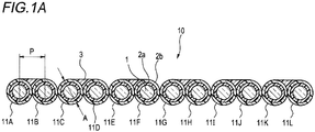
- Fig. 1A is a sectional view illustrating an example of the intermittent connection type optical fiber ribbon according to the first embodiment.
- Fig. 1B is a plan view illustrating an example of the intermittent connection type optical fiber ribbon according to the first embodiment, and is a view illustrating a state where a non-connection portion is widened in an arrange direction.
- an intermittent connection type optical fiber ribbon 10 is arranged to be in parallel as at least a part of a plurality (12 in the examples of Figs. 1A and 1B ) of optical fibers 11A to 11L come into contact with each other.
- the optical fibers 11A to 11L are single-core covering optical fibers including a glass fiber 1 and two-layer covering layers 2a (inner covering layer) and 2b (outer covering layer) which cover the glass fiber 1.
- a Young's modulus of the covering layer 2a may be equal to or less than 0.5 MPa.
- the Young's modulus of the inner covering layer 2a By setting the Young's modulus of the inner covering layer 2a to be equal to or less than 0.5 MPa, it is possible to suppress deterioration of lateral pressure characteristics due to reduction of the thickness of the covering layers (2a and 2b) of the optical fibers 11A to 11L.
- An outer diameter dimension A of the optical fibers 11A to 11L is equal to or less than 0.22 mm, and for example, the diameter of the glass fiber of the optical fibers 11A to 11L is 0.125 mm, and the diameter of the outer covering layer 2b is 0.20 ⁇ 0.02 mm.
- the covering layer 2b is colored with colors different from each other in order to make it possible to identify the optical fibers from each other, or may include a coloring layer at an outer circumference of the covering layer 2b.
- the adhesive resin 3 is, for example, an ultraviolet ray hardening type resin or a thermosetting type resin.
- the adhesive resin 3 is a resin having excellent peeling properties in order to make work for separating single cores of the optical fibers 11A to 11L easy.
- Areas which are coated with the adhesive resin 3 are, for example, as illustrated in Fig. 1A , only lower portions of the wires which link top portions of the optical fibers 11A to 11L to each other. Accordingly, it is possible to suppress the sectional area of a connection portion 4 with the adhesive resin 3 so as to be small. Since it is possible to reduce the sectional area of the connection portion 4, for example, it is possible to suppress the thickness of the intermittent connection type optical fiber ribbon 10 so as to be equal to or less than 0.26 mm. By suppressing the thickness of the intermittent connection type optical fiber ribbon 10, it is possible to improve the density of the optical fiber cable or the optical fiber cord which uses the intermittent connection type optical fiber ribbon 10.
- connection portion 4 in which adjacent optical fibers are connected to each other and a non-connection portion 5 in which the adjacent optical fiber wires are not connected to each other are intermittently provided in the longitudinal direction with the adhesive resin 3 used in coating.
- connection portion 4 connected with the adhesive resin 3 is provided such that an inter-center distance (hereinafter, referred to as inter-core pitch) P of the adjacent optical fibers in the intermittent connection type optical fiber ribbon 10 becomes 0.20 ⁇ 0.03 mm.
- Fig. 1B illustrates a state where the non-connection portion 5 of the intermittent connection type optical fiber ribbon 10 is widened in the arrange direction, but as illustrated in Fig. 1A , by setting a state where the optical fibers of the non-connection portion 5 are in contact with each other, it is possible to make the width of the intermittent connection type optical fiber ribbon 10 the minimum value.
- marking may be performed on at least one of the adhesive resin 3 and the optical fibers 11A to 11L.
- marking may be performed on the optical fibers 11A to 11L.
- FIG. 2A is a sectional view illustrating an example of the intermittent connection type optical fiber ribbon according to the second embodiment.
- Fig. 2B is a plan view illustrating an example of the intermittent connection type optical fiber ribbon according to the second embodiment, and is a view illustrating a state where the non-connection portion is widened in the arrange direction.
- areas similar to those of the configuration of the intermittent connection type optical fiber ribbon 10 of the first embodiment will be given the same reference numbers, and the description thereof will be omitted.
- the non-connection portion 5 is not provided in a longitudinal direction between two cores of at least a part of the optical fiber.
- the non-connection portion 5 is not provided between each of optical fibers 21A and 21B, 21C and 21D, 21E and 21F, 21G and 21H, 21I and 21J, and 21K and 21L.
- Fig. 2B illustrates a state where the non-connection portions 5 of the intermittent connection type optical fiber ribbon 20 is widened in the arrange direction, but as illustrated in Fig. 2A , by setting a state where the optical fibers of the non-connection portion 5 are in contact with each other, it is possible to make the width of the intermittent connection type optical fiber ribbon 20 the minimum value.
- the outer diameter dimension of the optical fibers 21A to 21L is equal to or less than 0.22 mm, and an inter-center distance of the adjacent optical fibers is 0.20 ⁇ 0.03 mm.
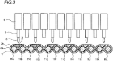
- a coating method of the adhesive resin 3 in a manufacturing method 1 of the intermittent connection type optical fiber ribbons 10 and 20 according to the first and second embodiments will be described using an example of coating the intermittent connection type optical fiber ribbon 10 of the first embodiment with the adhesive resin 3, with reference to Fig. 3 .
- 11 dispensers (adhesive resin supply device) 6 are installed in a tape width direction between each of the optical fibers 11A to 11L.
- an adhesive resin 8 is discharged from a nozzle 7, and a part between a predetermined optical fibers is intermittently coated with the adhesive resin 3.
- the adhesive resin 3 used in coating is hardened, the adjacent optical fibers are intermittently connected to each other.
- the intermittent connection type optical fiber ribbon 10 of 12 cores illustrated in Figs. 1A and 1B is manufactured.
- the ultraviolet ray hardening type resin as the adhesive resin 3, by irradiating the resin after the coating with an ultraviolet ray, it is possible to harden the adhesive resin 3.
- connection portion 4 of the intermittent connection type optical fiber ribbon 10 only one surface (side surface) of the plurality of optical fibers 11A to 11L in a state of being arranged to be in parallel is connected with the adhesive resin 3.
- the intermittent connection type optical fiber ribbon 20 according to the second embodiment (which is configured with the plurality of optical fibers 21A to 21L).
- the dispensers 6 may be disposed to be shifted in the longitudinal direction of the optical fibers 11A to 11L.
- the plurality of dispensers 6 may be disposed to be shifted to be different from each other in a zigzag manner.
- Fig. 4 is a schematic configuration view of the manufacturing device which is used in the manufacturing method 2 of the intermittent connection type optical fiber ribbon.
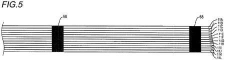
- Fig. 5 is a schematic view illustrating a state where a surface on which the plurality of optical fibers are arranged is coated with the marking for recognition.
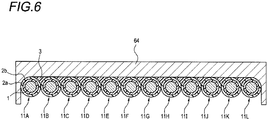
- Fig. 6 is a schematic view illustrating a dice-like rubbing member in the manufacturing device of Fig. 4 .
- Fig. 7 is a schematic view illustrating a slit processing portion in the manufacturing device of Fig. 4 .
- a manufacturing device 60 illustrated in Fig. 4 is configured with supply bobbins 61a to 611, an ink jet printer 62, a coating device 63, a rubbing member 64, an adhesive resin hardening device 65, a slit processing portion 66, and a winding bobbin 67.
- the intermittent connection type optical fiber ribbon 10 according to the first embodiment will be described, but the intermittent connection type optical fiber ribbon 20 according to the second embodiment can also be manufactured similarly.
- each of the optical fibers 11A to 11L are coated with, for example, a bar-like marking 68 by the ink jet printer 62 or the like. Since the surfaces are coated with the marking 68 before coating the adhesive resin 3, the marking 68 exists on a layer below the adhesive resin 3, and when mounting the optical fibers 11A to 11L on the optical fiber cord or on the optical fiber cable, it is possible to prevent the marking 68 from disappearing due to friction or the like.
- the coating device 63 by the coating device 63, one surface (side surface) of the plurality of optical fibers 11A to 11L in a state of being arranged to be in parallel is coated with the adhesive resin 3 as a resin coated surface. Unlike the coating method of the adhesive resin 3 in the manufacturing method 1 of the intermittent connection type optical fiber ribbon, the coating device 63 performs coating such that all of the optical fibers 11A to 11L adheres with the adhesive resin 3. By the smoothing process which will be described later, the adhesive resin 3 of the resin coated surface extends and is smoothed, and thus, the coating device 63 may perform the coating with the adhesive resin not being limited to a configuration in which the dispenser 6 is installed between each of the optical fibers 11A to 11L, as illustrated in Fig. 3 .
- the optical fibers 11A to 11L coated with the adhesive resin 3 allow the dice-like rubbing member 64 to pass therethrough as illustrated in Fig. 6 (smoothing process). By allowing the rubbing member 64 to pass, the adhesive resin 3 with which the optical fibers 11A to 11L is coated extends and the surface thereof is smoothed. Accordingly, when performing the coating with the adhesive resin 3 by the coating device 63, it is possible to easily smooth the surface even when the adhesive resin 3 rises or irregularity occurs.
- the adhesive resin hardening device 65 by using the adhesive resin hardening device 65, the adhesive resin of the surface layers of the optical fibers 11A to 11L is hardened.
- the adhesive resin 3 is, for example, the ultraviolet ray hardening type resin
- the adhesive resin hardening device 65 is an ultraviolet ray irradiating device or the like.
- slits are intermittently formed with respect to the adhesive resin 3 between the optical fibers.
- the areas at which the slits are formed become a non-connection portion at which the adjacent optical fibers are not connected to each other with the adhesive resin 3. Since the blades 66a to 66k are inserted from the surface which is not coated with the adhesive resin 3, a guide effect by a cavity between the optical fibers is likely to be obtained. Therefore, the position at which the slit is formed is shifted, and it is possible to suppress a defect that the optical fibers 11A to 11L are damaged or a defect that the slit cannot be reliably formed.
- the intermittent connection type optical fiber ribbon 10 is manufactured.
- the intermittent connection type optical fiber ribbon 20 is wound by the winding bobbin 67.
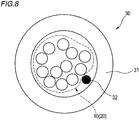
- Fig. 8 is a sectional view illustrating an example of the optical fiber cord which uses the intermittent connection type optical fiber ribbon according to the first embodiment or the second embodiment.
- an optical fiber cord 30 includes a jacket 31 and the intermittent connection type optical fiber ribbon 10 (20).
- the intermittent connection type optical fiber ribbon 10 (20) is covered with, for example, the cylindrical jacket 31.
- the intermittent connection type optical fiber ribbon 10 (20) may be bound by an inclusion 32 by Kevlar or the like.
- Fig. 9 is a view illustrating an example of the slotless type optical fiber cable which uses the intermittent connection type optical fiber ribbon 10 of the first embodiment.
- Fig. 10 is a view illustrating an example of the tape slot type optical fiber cable which uses the intermittent connection type optical fiber ribbon 10 of the first embodiment.
- the optical fiber cable illustrated in Fig. 9 is a slotless type optical fiber cable 40 including a cylindrical tube 42 and the plurality of intermittent connection type optical fiber ribbons 10.
- the plurality of intermittent connection type optical fiber ribbons 10 may be bound by an inclusion 41, such as an aramid fiber.
- the plurality of intermittent connection type optical fiber ribbons 10 may include markings different from each other.
- a structure in which the resin which becomes the tube 42 is extruded and formed around the intermittent connection type optical fiber ribbons 10 while twisting the plurality of bound intermittent connection type optical fiber ribbons 10, and the intermittent connection type optical fiber ribbon 10 is formed being covered with a jacket 44 together with a tension member 43.
- absorptive yarn may be inserted into the tube 42.
- a hardening material such as PBT or HDPE, is used.
- 45 indicates a tear string.
- the optical fiber cable illustrated in Fig. 10 is a tape slot type optical fiber cable 50 including a slot rod 54 having a plurality of slot grooves 51, and the plurality of intermittent connection type optical fiber ribbons 10.
- the tape slot type optical fiber cable 50 has a structure in which the plurality of slot grooves 51 are provided in a radial shape in the slot rod 54 having a tension member 52 at the center thereof.
- the plurality of intermittent connection type optical fiber ribbons 10 are accommodated in a state of being respectively layered on the plurality of slot grooves 51.
- the plurality of intermittent connection type optical fiber ribbons 10 may have markings different from each other.
- a jacket 53 is formed around the slot rod 54.
- the intermittent connection type optical fiber ribbon 10 which is used in the optical fiber cables 40 and 50 may be the intermittent connection type optical fiber ribbon 20 of the second embodiment.
- the intermittent connection type optical fiber ribbon 10 (20) at least a part of the plurality of optical fibers 11A to 11L (21A to 21L) in a state of being arranged to be in parallel come into contact with each other, and between a part or the entirety of the optical fibers, the connection portion 4 at which the adjacent optical fibers are connected to each other with the adhesive resin 3, and the non-connection portion 5 at which the adjacent optical fibers are not connected to each other with the adhesive resin 3, are intermittently provided in the longitudinal direction.
- the outer diameter dimension of the optical fibers 11A to 11L (21A to 21L) is equal to or less than 0.22 mm, and the inter-center distance of the adjacent optical fibers is 0.20 ⁇ 0.03 mm.
- the intermittent connection type optical fiber ribbon 10 (20) according to the first embodiment and the second embodiment can make the sectional area smaller than that of the intermittent connection type optical fiber ribbon of the related art.
- the optical fiber cord 30 including the intermittent connection type optical fiber ribbons 10 (20) which can make the sectional area smaller than that of the intermittent connection type optical fiber ribbon of the related art, can make the outer diameter thereof smaller than that of the optical fiber cord of the related art. In addition, it is possible to improve the density to be higher than that of the optical fiber cord 30.
- the slotless type optical fiber cable 40 which uses the plurality of intermittent connection type optical fiber ribbons 10 (20) can make the density higher than that of the optical fiber cable of the related art.
- the optical fiber cable 40 having the same outer diameter as that of the optical fiber cable of the related art can mount 63 intermittent connection type optical fiber ribbons 10 (20) having 12 cores according to the first embodiment or the second embodiment, and the number of optical fibers can be 756.
- the outer diameter thereof can be made smaller than that of the optical fiber cable of the related art.
- the number of optical fibers can increase to be greater than that of the optical fiber cable having the same outer diameter on which the intermittent connection type optical fiber ribbon of the related art is mounted.
- the tape slot type optical fiber cable 50 of the embodiment can make the density higher than that of the optical fiber cable of the related art.
- the outer diameter thereof can be made smaller than that of the optical fiber cable of the related art.
- an intermittent connection type optical fiber ribbon 100 of Comparative Example 1 has a structure in which optical fibers 110 having an outer diameter of 0.25 mm come into contact with each other and are arranged to be in parallel, and the periphery thereof is coated with an adhesive resin 103.
- the inter-core pitch P of the intermittent connection type optical fiber ribbon 100 is 0.25 mm
- the width W of the intermittent connection type optical fiber ribbon 100 is 3.04 mm.
- the structure of the optical fiber 110 is a single-core covering optical fiber including a glass fiber 101 and two-layer covering layers 102a (inner covering layer) and 102b (outer covering layer) which cover the glass fiber 101.
- the sectional area of the intermittent connection type optical fiber ribbon 100 is 0.765 mm 2 .
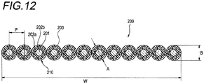
- an intermittent connection type optical fiber ribbon 200 of Comparative Example 2 has a structure of being arranged to be in parallel after coating the periphery of each of the optical fibers having an outer diameter of 0.20 mm with an adhesive resin 203, and in which the inter-core pitch P is 0.25 mm.
- the width W of the intermittent connection type optical fiber ribbon 200 is 3.00 mm.
- the structure of an optical fiber 210 is a single-core covering optical fiber including a glass fiber 201 and two-layer covering layers 202a (inner covering layer) and 202b (outer covering layer) which cover the glass fiber 201.
- the intermittent connection type optical fiber ribbon 200 When the intermittent connection type optical fiber ribbon 200 is simply approximated as an aggregate of the optical fiber, and a thickness B (outer diameter A) of the aggregate is 0.25 mm, the sectional area of the intermittent connection type optical fiber ribbon 200 is 0.589 mm 2 , and a decrease rate is approximately 23% compared to Comparative Example 1 by the cross-sectional ratio.
- the outer diameter A of the optical fibers 11A to 11L is 0.20 mm
- the inter-core pitch P is 0.20 mm
- the width of the intermittent connection type optical fiber ribbon 10 is 2.40 mm.
- Comparative Example 1 while the outer diameter of the optical fiber is 0.25 mm which is generally used, in Comparative Example 2 and Example, the optical fiber which can be mounted to the optical fiber cable with high density and of which the outer diameter is 0.20 mm which is a small outer diameter, is used.
- the sectional area of the intermittent connection type optical fiber ribbon is made in Comparative Example 2 or Example in which the outer diameter of the optical fiber is small, smaller compared to that in Comparative Example 1, but when the decrease rate of the sectional area of Example is approximately 43%, the decrease rate increases to be greater than approximately 23% which is the decrease rate of the sectional area of Comparative Example 2.
- Example which is the structure of the intermittent connection type optical fiber ribbon 10 of the first embodiment it is possible to make the sectional area smaller than that of Example 2 which is the intermittent connection type optical fiber ribbon of the related art.
- the sectional area is approximately 0.457 mm 2 , and it is possible to make the sectional area smaller than that of Comparative Example 2.
Landscapes
- Physics & Mathematics (AREA)
- General Physics & Mathematics (AREA)
- Optics & Photonics (AREA)
- Engineering & Computer Science (AREA)
- Manufacturing & Machinery (AREA)
- Mechanical Coupling Of Light Guides (AREA)
Abstract
Description
- The present invention relates to an intermittent connection type optical fiber ribbon, a manufacturing method of an intermittent connection type optical fiber ribbon, an optical fiber cable, and an optical fiber cord.
- The present application is based on Japanese Patent Application No.
2016-031998 filed on February 23, 2016 - In
PTL 1, an intermittent connection type optical fiber ribbon in which a connection portion at which adjacent optical fibers are connected to each other with an adhesive resin, and a non-connection portion at which the adjacent optical fibers are not connected to each other with the adhesive resin, are intermittently provided in a longitudinal direction, in a state where a plurality of optical fibers are arranged to be in parallel, is described. - Patent Document 1:
JP-A-2013-88617 - According to an aspect of the present invention, there is an intermittent connection type optical fiber ribbon in which at least a part of a plurality of optical fibers in a state of being arranged to be in parallel come into contact with each other, and between a part or the entirety of the optical fibers, a connection portion at which the adjacent optical fibers are connected to each other with an adhesive resin, and a non-connection portion at which the adjacent optical fibers are not connected to each other with the adhesive resin, are intermittently provided in the longitudinal direction, in which an outer diameter dimension of the optical fiber is equal to or less than 0.22 mm, and an inter-center distance of the adjacent optical fibers is 0.20 ± 0.03 mm.
- According to another aspect of the present invention, there is provided an optical fiber cable including: a cylindrical tube; and the plurality of intermittent connection type optical fiber ribbons, in which the plurality of intermittent connection type optical fiber ribbons are covered with the tube.
- According to still another aspect of the present invention, there is provided an optical fiber cable including: a slot rod including a plurality of slot grooves; and the plurality of intermittent connection type optical fiber ribbons, in which the plurality of intermittent connection type optical fiber ribbons are respectively accommodated in the slot grooves.
- According to still another aspect of the present invention, there is provided an optical fiber cord including: a jacket; and the intermittent connection type optical fiber ribbon, in which the intermittent connection type optical fiber ribbon is covered with the jacket.
- A manufacturing method of an intermittent connection type optical fiber ribbon is for manufacturing the intermittent connection type optical fiber ribbon in which at least a part of a plurality of optical fibers in a state of being arranged to be in parallel come into contact with each other, and between a part or the entirety of the optical fibers, a connection portion at which the adjacent optical fibers are connected to each other with an adhesive resin, and a non-connection portion at which the adjacent optical fibers are not connected to each other with the adhesive resin, are intermittently provided in the longitudinal direction, the method including: a step of coating a surface of the optical fiber with marking for recognition by arranging the plurality of optical fibers to be in parallel; a step of coating the plurality of arranged optical fibers with the adhesive resin; a smoothing step of smoothing the adhesive resin used in coating; a step of providing the connection portion by hardening the adhesive resin; and a step of providing the non-connection portion by intermittently forming a slit in a longitudinal direction between a part or the entirety of optical fibers, from the surface opposite to the resin coated surface.
-
-
Fig. 1A is a sectional view illustrating an example of an intermittent connection type optical fiber ribbon according to a first embodiment. -
Fig. 1B is a plan view illustrating an example of the intermittent connection type optical fiber ribbon according to the first embodiment, and is a view illustrating a state where a non-connection portion is widened in an arrange direction. -
Fig. 2A is a sectional view illustrating an example of an intermittent connection type optical fiber ribbon according to a second embodiment. -
Fig. 2B is a plan view illustrating an example of the intermittent connection type optical fiber ribbon according to a second embodiment, and is a view illustrating a state where the non-connection portion is widened in the arrange direction. -
Fig. 3 is a view illustrating an example of a method for coating the intermittent connection type optical fiber ribbon according to the first embodiment with an adhesive resin. -
Fig. 4 is a schematic configuration view of a manufacturing device which is used as one example of the manufacturing method of the intermittent connection type optical fiber ribbon according to the first embodiment or the second embodiment. -
Fig. 5 is a schematic view illustrating a state where the plurality of optical fibers are arranged and the surface is coated with marking for recognition in the manufacturing device ofFig. 4 . -
Fig. 6 is a schematic view illustrating a dice-like rubbing member in the manufacturing device ofFig. 4 . -
Fig. 7 is a schematic view illustrating a slit processing portion in the manufacturing device ofFig. 4 . -
Fig. 8 is a sectional view illustrating an example of an optical fiber cord in which the intermittent connection type optical fiber ribbon according to the first embodiment or the second embodiment is used. -
Fig. 9 is a sectional view illustrating an example of a slotless type optical fiber cable in which the intermittent connection type optical fiber ribbon according to the first embodiment and the second embodiment is used. -
Fig. 10 is a sectional view illustrating an example of a slot type optical fiber cable in which the intermittent connection type optical fiber ribbon according to the first embodiment and the second embodiment is used. -
Fig. 11 is a sectional view illustrating an intermittent connection type optical fiber ribbon of Comparative Example 1. -
Fig. 12 is a sectional view illustrating an intermittent connection type optical fiber ribbon of Comparative Example 2. - When an intermittent connection type optical fiber ribbon is used as an optical fiber ribbon which is accommodated in an optical fiber cable or in an optical fiber cord, it is possible to easily perform detaching of a desirable optical fiber at the time of intermediate branching.
- In order to improve the density of the optical fiber cable or the optical fiber cord which accommodates the intermittent connection type optical fiber ribbon having excellent workability at the time of intermediate branching therein as described above, it is detected that the outer diameter of the optical fiber which is used in the intermittent connection type optical fiber ribbon is generally 250 µm (0.25 mm) to 220 µm (0.22 mm) (for example, PTL 1).
- However, in the intermittent connection type optical fiber ribbon described in
PTL 1, since an adhesive resin exists between each of the optical fibers, it is not possible to reduce a space area in the optical fiber cable or in the optical fiber cord, and to sufficiently improve the density of the optical fiber cable or the optical fiber cord. - Here, an object of the disclosure is to provide an intermittent connection type optical fiber ribbon which can improve the density of an optical fiber cable and an optical fiber cord, and an optical fiber cable and an optical fiber cord which use the intermittent connection type optical fiber ribbon.
- According to the present invention, it is possible to provide an intermittent connection type optical fiber ribbon which can improve the density of an optical fiber cable and an optical fiber cord, and an optical fiber cable and an optical fiber cord which use the intermittent connection type optical fiber ribbon.
- First, embodiments of the present invention will be listed and described.
- (1) An intermittent connection type optical fiber ribbon according to an embodiment of the present invention is an intermittent connection type optical fiber ribbon in which at least a part of a plurality of optical fibers in a state of being arranged to be in parallel come into contact with each other, and between a part or the entirety of the optical fibers, a connection portion at which the adjacent optical fibers are connected to each other with an adhesive resin, and a non-connection portion at which the adjacent optical fibers are not connected to each other with the adhesive resin, are intermittently provided in the longitudinal direction, in which an outer diameter dimension of the optical fiber is equal to or less than 0.22 mm, and an inter-center distance of the adjacent optical fibers is 0.20 ± 0.03 mm.
In the intermittent connection type optical fiber ribbon of the above-described (1), at least a part of the adjacent optical fibers come into contact with each other, the outer diameter dimension of the optical fiber is equal to or less than 0.22 mm, and the inter-center distance of the adjacent optical fibers is 0.20 ± 0.03 mm, and thus, it is possible to make a sectional area smaller than that of the intermittent connection type optical fiber ribbon of the related art, and to improve the density of the optical fiber cable or the optical fiber cord when the intermittent connection type optical fiber ribbon is used in the optical fiber cable or in the optical fiber cord. - (2) The thickness of the intermittent connection type optical fiber ribbon is equal to or less than 0.26 mm.
By suppressing the thickness of the intermittent connection type optical fiber ribbon so as to be equal to or less than 0.26 mm, it is possible to improve the density of the optical fiber cable or the optical fiber cord. - (3) Marking is performed on at least one of the adhesive resin and the optical fiber.
Since the marking is performed on at least one of the adhesive resin and the optical fiber, it is possible to easily recognize the intermittent connection type optical fiber ribbon at the time of intermediate branching. - (4) The optical fiber includes a glass fiber and two covering layers which cover the glass fiber, and a Young's modulus of the inner covering layer of the two covering layers is equal to or less than 0.5 MPa.
Since the Young's modulus of the inner covering layer of the optical fiber is equal to or less than 0.5 MPa, it is possible to suppress deterioration of lateral pressure characteristics by making the thickness of the covering layer of the optical fiber thin. - (5) Only a side surface of the intermittent connection type optical fiber ribbon is coated with the adhesive resin.
Since the area coated with the adhesive resin is only a side surface of the intermittent connection type optical fiber ribbon, it is possible to suppress the sectional area of the connection portion with the adhesive resin so as to be small. - (6) An optical fiber cable according to an embodiment includes: a cylindrical tube; and the plurality of intermittent connection type optical fiber ribbons according to any one of the above-described (1) to (5), in which the plurality of intermittent connection type optical fiber ribbons are covered with the tube.
- (7) An optical fiber cable includes: a slot rod including a plurality of slot grooves; and the plurality of intermittent connection type optical fiber ribbons according to any one of the above-described (1) to (5), in which the plurality of intermittent connection type optical fiber ribbons are respectively accommodated in the slot grooves.
In the optical fiber cables of the above-described (6) and (7), since the plurality of intermittent connection type optical fiber ribbons described in any one of the above-described (1) to (5) are mounted, it is possible to make the density higher than that of the optical fiber cable of the related art. In addition, depending on the same number of cores, it is possible to make the outer diameter thereof smaller than that of the optical fiber cable of the related art. - (8) An optical fiber cord according to the embodiment of the present invention includes: a jacket; and the intermittent connection type optical fiber ribbon according to any one of the above-described (1) to (5), in which the intermittent connection type optical fiber ribbon is covered with the jacket.
It is possible to make the outer diameter of the optical fiber cord smaller than that of the related art. In addition, it is possible to make the density of the optical fiber cord higher than that of the related art. - (9) A manufacturing method of an intermittent connection type optical fiber ribbon according to the present invention is for manufacturing the intermittent connection type optical fiber ribbon according to any one of the above-described (1) to (5), the method including: a step of coating a surface of the optical fiber with marking for recognition by arranging the plurality of optical fibers to be in parallel; a step of coating the plurality of arranged optical fibers with the adhesive resin to be in parallel; a smoothing step of smoothing the adhesive resin used in coating; a step of providing the connection portion by hardening the adhesive resin; and a step of providing the non-connection portion by intermittently forming a slit in a longitudinal direction between a part or the entirety of optical fibers, from the surface opposite to the resin coated surface.
In the intermittent connection type optical fiber ribbon manufactured by the manufacturing method of the above-described (9), it is possible to make the sectional area smaller than that of the intermittent connection type optical fiber ribbon of the related art, and when the intermittent connection type optical fiber ribbon is used in the optical fiber cable or in the optical fiber cord, it is possible to improve the density of the optical fiber cable or the optical fiber cord. - (10) In the manufacturing method of an intermittent connection type optical fiber ribbon of the above-described (9), the smoothing step of smoothing smooths the adhesive resin by allowing the plurality of arranged optical fibers to pass through a dice-like rubbing member.
It is possible to easily smooth the surface even when the adhesive resin rises or irregularity occurs when coating the surface with the adhesive resin. - Specific examples of the intermittent connection type optical fiber ribbon, the optical fiber cable, and the optical fiber cord according to embodiments of the present invention will be described with reference to the drawings hereinafter.
- In addition, the present invention is not limited to the examples, is illustrated by the range of claims, and meanings equivalent to those within the range of claims and all of the changes within the range are included.
- First, an intermittent connection type optical fiber ribbon according to a first embodiment will be described with reference to the drawings.
Fig. 1A is a sectional view illustrating an example of the intermittent connection type optical fiber ribbon according to the first embodiment.Fig. 1B is a plan view illustrating an example of the intermittent connection type optical fiber ribbon according to the first embodiment, and is a view illustrating a state where a non-connection portion is widened in an arrange direction. - As illustrated in
Figs. 1A and1B , an intermittent connection typeoptical fiber ribbon 10 according to the first embodiment is arranged to be in parallel as at least a part of a plurality (12 in the examples ofFigs. 1A and1B ) ofoptical fibers 11A to 11L come into contact with each other. Theoptical fibers 11A to 11L are single-core covering optical fibers including aglass fiber 1 and two-layer covering layers 2a (inner covering layer) and 2b (outer covering layer) which cover theglass fiber 1. In addition, a Young's modulus of thecovering layer 2a may be equal to or less than 0.5 MPa. By setting the Young's modulus of theinner covering layer 2a to be equal to or less than 0.5 MPa, it is possible to suppress deterioration of lateral pressure characteristics due to reduction of the thickness of the covering layers (2a and 2b) of theoptical fibers 11A to 11L. - An outer diameter dimension A of the
optical fibers 11A to 11L is equal to or less than 0.22 mm, and for example, the diameter of the glass fiber of theoptical fibers 11A to 11L is 0.125 mm, and the diameter of theouter covering layer 2b is 0.20 ± 0.02 mm. In addition, in theoptical fibers 11A to 11L, thecovering layer 2b is colored with colors different from each other in order to make it possible to identify the optical fibers from each other, or may include a coloring layer at an outer circumference of thecovering layer 2b. - In addition, a part of the surfaces of the plurality of
optical fibers 11A to 11L which are arranged to be in parallel is coated with anadhesive resin 3 for connecting the optical fibers to each other, and theoptical fibers 11A to 11L are arranged to be arranged in a shape of a tape. Theadhesive resin 3 is, for example, an ultraviolet ray hardening type resin or a thermosetting type resin. In addition, it is preferable that theadhesive resin 3 is a resin having excellent peeling properties in order to make work for separating single cores of theoptical fibers 11A to 11L easy. - Areas which are coated with the
adhesive resin 3 are, for example, as illustrated inFig. 1A , only lower portions of the wires which link top portions of theoptical fibers 11A to 11L to each other. Accordingly, it is possible to suppress the sectional area of a connection portion 4 with theadhesive resin 3 so as to be small. Since it is possible to reduce the sectional area of the connection portion 4, for example, it is possible to suppress the thickness of the intermittent connection typeoptical fiber ribbon 10 so as to be equal to or less than 0.26 mm. By suppressing the thickness of the intermittent connection typeoptical fiber ribbon 10, it is possible to improve the density of the optical fiber cable or the optical fiber cord which uses the intermittent connection typeoptical fiber ribbon 10. - As described above, in the intermittent connection type
optical fiber ribbon 10, the connection portion 4 in which adjacent optical fibers are connected to each other and anon-connection portion 5 in which the adjacent optical fiber wires are not connected to each other are intermittently provided in the longitudinal direction with theadhesive resin 3 used in coating. In addition, the connection portion 4 connected with theadhesive resin 3 is provided such that an inter-center distance (hereinafter, referred to as inter-core pitch) P of the adjacent optical fibers in the intermittent connection typeoptical fiber ribbon 10 becomes 0.20 ± 0.03 mm. - In addition,
Fig. 1B illustrates a state where thenon-connection portion 5 of the intermittent connection typeoptical fiber ribbon 10 is widened in the arrange direction, but as illustrated inFig. 1A , by setting a state where the optical fibers of thenon-connection portion 5 are in contact with each other, it is possible to make the width of the intermittent connection typeoptical fiber ribbon 10 the minimum value. - By the above-described configuration, in the intermittent connection type
optical fiber ribbon 10, it is possible to make the sectional area smaller than that of the intermittent connection type optical fiber ribbon of the related art. - In addition, at the time of intermediate branching in the optical fiber cable which uses the plurality of intermittent connection type
optical fiber ribbons 10, in order to make it possible to easily recognize the intermittent connection typeoptical fiber ribbon 10, marking may be performed on at least one of theadhesive resin 3 and theoptical fibers 11A to 11L. In addition, when there is a marking on theadhesive resin 3, when mounting theoptical fibers 11A to 11L on the optical fiber cord or on the optical fiber cable, there is a possibility that the marking disappears due to friction or the like. Therefore, it is preferable that the marking is performed on theoptical fibers 11A to 11L. - Next, an intermittent connection type optical fiber ribbon according to a second embodiment will be described with reference to the drawings.
Fig. 2A is a sectional view illustrating an example of the intermittent connection type optical fiber ribbon according to the second embodiment.Fig. 2B is a plan view illustrating an example of the intermittent connection type optical fiber ribbon according to the second embodiment, and is a view illustrating a state where the non-connection portion is widened in the arrange direction. In addition, areas similar to those of the configuration of the intermittent connection typeoptical fiber ribbon 10 of the first embodiment will be given the same reference numbers, and the description thereof will be omitted. - As illustrated in
Figs. 2A and2B , in an intermittent connection typeoptical fiber ribbon 20, thenon-connection portion 5 is not provided in a longitudinal direction between two cores of at least a part of the optical fiber. For example, in the examples ofFigs. 2A and2B , thenon-connection portion 5 is not provided between each ofoptical fibers - In addition,
Fig. 2B illustrates a state where thenon-connection portions 5 of the intermittent connection typeoptical fiber ribbon 20 is widened in the arrange direction, but as illustrated inFig. 2A , by setting a state where the optical fibers of thenon-connection portion 5 are in contact with each other, it is possible to make the width of the intermittent connection typeoptical fiber ribbon 20 the minimum value. - Even in the intermittent connection type optical fiber ribbon having the above-described configuration, similar to the configuration of the intermittent connection type
optical fiber ribbon 10 of the first embodiment, the outer diameter dimension of theoptical fibers 21A to 21L is equal to or less than 0.22 mm, and an inter-center distance of the adjacent optical fibers is 0.20 ± 0.03 mm. - A coating method of the
adhesive resin 3 in amanufacturing method 1 of the intermittent connection typeoptical fiber ribbons optical fiber ribbon 10 of the first embodiment with theadhesive resin 3, with reference toFig. 3 . - As illustrated in
Fig. 3 ,11 dispensers (adhesive resin supply device) 6 are installed in a tape width direction between each of theoptical fibers 11A to 11L. In addition, by periodically applying a pressure to thedispenser 6, anadhesive resin 8 is discharged from anozzle 7, and a part between a predetermined optical fibers is intermittently coated with theadhesive resin 3. As theadhesive resin 3 used in coating is hardened, the adjacent optical fibers are intermittently connected to each other. In this manner, the intermittent connection typeoptical fiber ribbon 10 of 12 cores illustrated inFigs. 1A and1B is manufactured. For example, by using the ultraviolet ray hardening type resin as theadhesive resin 3, by irradiating the resin after the coating with an ultraviolet ray, it is possible to harden theadhesive resin 3. In a case ofFig. 3 , in the connection portion 4 of the intermittent connection typeoptical fiber ribbon 10, only one surface (side surface) of the plurality ofoptical fibers 11A to 11L in a state of being arranged to be in parallel is connected with theadhesive resin 3. - In addition, when control of combination or discharge timing of the
nozzle 7 through which theadhesive resin 8 is discharged is changed, it is also possible to manufacture the intermittent connection typeoptical fiber ribbon 20 according to the second embodiment (which is configured with the plurality ofoptical fibers 21A to 21L). - In addition, in a case where the outer diameter dimension of the
optical fibers 11A to 11L is small, when the plurality ofdispensers 6 are horizontally disposed in one row, an interval between theadjacent dispensers 6 becomes narrow, the disposition becomes difficult, and thus, thedispensers 6 may be disposed to be shifted in the longitudinal direction of theoptical fibers 11A to 11L. For example, the plurality ofdispensers 6 may be disposed to be shifted to be different from each other in a zigzag manner. - Next, a manufacturing method 2 of the intermittent connection type
optical fiber ribbons Figs. 4 to 7 .Fig. 4 is a schematic configuration view of the manufacturing device which is used in the manufacturing method 2 of the intermittent connection type optical fiber ribbon.Fig. 5 is a schematic view illustrating a state where a surface on which the plurality of optical fibers are arranged is coated with the marking for recognition.Fig. 6 is a schematic view illustrating a dice-like rubbing member in the manufacturing device ofFig. 4 .Fig. 7 is a schematic view illustrating a slit processing portion in the manufacturing device ofFig. 4 . - A
manufacturing device 60 illustrated inFig. 4 is configured withsupply bobbins 61a to 611, anink jet printer 62, acoating device 63, a rubbingmember 64, an adhesiveresin hardening device 65, aslit processing portion 66, and a windingbobbin 67. - In the following description, manufacturing of the intermittent connection type
optical fiber ribbon 10 according to the first embodiment will be described, but the intermittent connection typeoptical fiber ribbon 20 according to the second embodiment can also be manufactured similarly. - As illustrated in
Fig. 5 , by setting a state where theoptical fibers 11A to 11L supplied from each of thesupply bobbins 61a to 611 are arranged to be in parallel, surfaces of each of theoptical fibers 11A to 11L are coated with, for example, a bar-like marking 68 by theink jet printer 62 or the like. Since the surfaces are coated with the marking 68 before coating theadhesive resin 3, the marking 68 exists on a layer below theadhesive resin 3, and when mounting theoptical fibers 11A to 11L on the optical fiber cord or on the optical fiber cable, it is possible to prevent the marking 68 from disappearing due to friction or the like. - Next, by the
coating device 63, one surface (side surface) of the plurality ofoptical fibers 11A to 11L in a state of being arranged to be in parallel is coated with theadhesive resin 3 as a resin coated surface. Unlike the coating method of theadhesive resin 3 in themanufacturing method 1 of the intermittent connection type optical fiber ribbon, thecoating device 63 performs coating such that all of theoptical fibers 11A to 11L adheres with theadhesive resin 3. By the smoothing process which will be described later, theadhesive resin 3 of the resin coated surface extends and is smoothed, and thus, thecoating device 63 may perform the coating with the adhesive resin not being limited to a configuration in which thedispenser 6 is installed between each of theoptical fibers 11A to 11L, as illustrated inFig. 3 . - The
optical fibers 11A to 11L coated with theadhesive resin 3 allow the dice-like rubbingmember 64 to pass therethrough as illustrated inFig. 6 (smoothing process). By allowing the rubbingmember 64 to pass, theadhesive resin 3 with which theoptical fibers 11A to 11L is coated extends and the surface thereof is smoothed. Accordingly, when performing the coating with theadhesive resin 3 by thecoating device 63, it is possible to easily smooth the surface even when theadhesive resin 3 rises or irregularity occurs. - Next, by using the adhesive
resin hardening device 65, the adhesive resin of the surface layers of theoptical fibers 11A to 11L is hardened. In a case where theadhesive resin 3 is, for example, the ultraviolet ray hardening type resin, the adhesiveresin hardening device 65 is an ultraviolet ray irradiating device or the like. - Next, as illustrated in
Fig. 7 , from the surface which is not coated with theadhesive resin 3 in theoptical fibers 11A to 11L, by intermittently insertingblades 66a to 66k (for example, a rotating blade in which round teeth are installed in a roller) between predetermined optical fibers at a predetermined insertion pattern and timing, slits are intermittently formed with respect to theadhesive resin 3 between the optical fibers. The areas at which the slits are formed become a non-connection portion at which the adjacent optical fibers are not connected to each other with theadhesive resin 3. Since theblades 66a to 66k are inserted from the surface which is not coated with theadhesive resin 3, a guide effect by a cavity between the optical fibers is likely to be obtained. Therefore, the position at which the slit is formed is shifted, and it is possible to suppress a defect that theoptical fibers 11A to 11L are damaged or a defect that the slit cannot be reliably formed. - As described above, the intermittent connection type
optical fiber ribbon 10 is manufactured. In addition, for example, by changing the insertion pattern and the timing of theblades 66a to 66k, when changing the area at which the slit is formed, it is possible to manufacture the intermittent connection typeoptical fiber ribbon 20 according to the second embodiment. In addition, the manufactured intermittent connection type optical fiber ribbon 10 (20) is wound by the windingbobbin 67. - Next, the optical fiber cord according to the embodiment will be described with reference to
Fig. 8. Fig. 8 is a sectional view illustrating an example of the optical fiber cord which uses the intermittent connection type optical fiber ribbon according to the first embodiment or the second embodiment. - As illustrated in
Fig. 8 , anoptical fiber cord 30 includes ajacket 31 and the intermittent connection type optical fiber ribbon 10 (20). In addition, the intermittent connection type optical fiber ribbon 10 (20) is covered with, for example, thecylindrical jacket 31. In addition, the intermittent connection type optical fiber ribbon 10 (20) may be bound by aninclusion 32 by Kevlar or the like. - Next, with reference to
Figs. 9 and10 , the optical fiber cable according to the embodiment will be described.Fig. 9 is a view illustrating an example of the slotless type optical fiber cable which uses the intermittent connection typeoptical fiber ribbon 10 of the first embodiment.Fig. 10 is a view illustrating an example of the tape slot type optical fiber cable which uses the intermittent connection typeoptical fiber ribbon 10 of the first embodiment. - The optical fiber cable illustrated in
Fig. 9 is a slotless typeoptical fiber cable 40 including acylindrical tube 42 and the plurality of intermittent connection typeoptical fiber ribbons 10. The plurality of intermittent connection typeoptical fiber ribbons 10 may be bound by aninclusion 41, such as an aramid fiber. In addition, the plurality of intermittent connection typeoptical fiber ribbons 10 may include markings different from each other. In addition, a structure in which the resin which becomes thetube 42 is extruded and formed around the intermittent connection typeoptical fiber ribbons 10 while twisting the plurality of bound intermittent connection typeoptical fiber ribbons 10, and the intermittent connection typeoptical fiber ribbon 10 is formed being covered with ajacket 44 together with atension member 43. In addition, in a case where waterproof properties are required, absorptive yarn may be inserted into thetube 42. As the resin which becomes thecylindrical tube 42, for example, a hardening material, such as PBT or HDPE, is used. In addition, 45 indicates a tear string. - The optical fiber cable illustrated in
Fig. 10 is a tape slot typeoptical fiber cable 50 including aslot rod 54 having a plurality ofslot grooves 51, and the plurality of intermittent connection typeoptical fiber ribbons 10. The tape slot typeoptical fiber cable 50 has a structure in which the plurality ofslot grooves 51 are provided in a radial shape in theslot rod 54 having atension member 52 at the center thereof. The plurality of intermittent connection typeoptical fiber ribbons 10 are accommodated in a state of being respectively layered on the plurality ofslot grooves 51. The plurality of intermittent connection typeoptical fiber ribbons 10 may have markings different from each other. In addition, ajacket 53 is formed around theslot rod 54. - In addition, the intermittent connection type
optical fiber ribbon 10 which is used in theoptical fiber cables optical fiber ribbon 20 of the second embodiment. - Above, in the intermittent connection type optical fiber ribbon 10 (20) according to the first embodiment and the second embodiment which are described in detail, at least a part of the plurality of
optical fibers 11A to 11L (21A to 21L) in a state of being arranged to be in parallel come into contact with each other, and between a part or the entirety of the optical fibers, the connection portion 4 at which the adjacent optical fibers are connected to each other with theadhesive resin 3, and thenon-connection portion 5 at which the adjacent optical fibers are not connected to each other with theadhesive resin 3, are intermittently provided in the longitudinal direction. In addition, the outer diameter dimension of theoptical fibers 11A to 11L (21A to 21L) is equal to or less than 0.22 mm, and the inter-center distance of the adjacent optical fibers is 0.20 ± 0.03 mm. - Accordingly, the intermittent connection type optical fiber ribbon 10 (20) according to the first embodiment and the second embodiment can make the sectional area smaller than that of the intermittent connection type optical fiber ribbon of the related art.
- As described above, the
optical fiber cord 30 including the intermittent connection type optical fiber ribbons 10 (20) which can make the sectional area smaller than that of the intermittent connection type optical fiber ribbon of the related art, can make the outer diameter thereof smaller than that of the optical fiber cord of the related art. In addition, it is possible to improve the density to be higher than that of theoptical fiber cord 30. - In addition, the slotless type
optical fiber cable 40 which uses the plurality of intermittent connection type optical fiber ribbons 10 (20) can make the density higher than that of the optical fiber cable of the related art. For example, in 432 core optical fiber cables which use the intermittent type optical fiber ribbon (the diameter of the core is 0.25 mm and the inter-core pitch is 0.25 mm) of the related art, 36 intermittent connection type optical fiber ribbons having 12 cores are mounted in the cylindrical tube. Meanwhile, theoptical fiber cable 40 having the same outer diameter as that of the optical fiber cable of the related art can mount 63 intermittent connection type optical fiber ribbons 10 (20) having 12 cores according to the first embodiment or the second embodiment, and the number of optical fibers can be 756. In addition, when the number of cores is the same, the outer diameter thereof can be made smaller than that of the optical fiber cable of the related art. - In addition, in the
optical fiber cable 50 which uses the intermittent connection type optical fiber ribbon 10 (20), similarly, the number of optical fibers can increase to be greater than that of the optical fiber cable having the same outer diameter on which the intermittent connection type optical fiber ribbon of the related art is mounted. In other words, the tape slot typeoptical fiber cable 50 of the embodiment can make the density higher than that of the optical fiber cable of the related art. In addition, when the number of cores is the same, the outer diameter thereof can be made smaller than that of the optical fiber cable of the related art. - Next, Example and Comparative Examples 1 and 2 will be described.
- As illustrated in
Fig. 11 , an intermittent connection typeoptical fiber ribbon 100 of Comparative Example 1 has a structure in whichoptical fibers 110 having an outer diameter of 0.25 mm come into contact with each other and are arranged to be in parallel, and the periphery thereof is coated with anadhesive resin 103. The inter-core pitch P of the intermittent connection typeoptical fiber ribbon 100 is 0.25 mm, and the width W of the intermittent connection typeoptical fiber ribbon 100 is 3.04 mm. In addition, the structure of theoptical fiber 110 is a single-core covering optical fiber including aglass fiber 101 and two-layer covering layers 102a (inner covering layer) and 102b (outer covering layer) which cover theglass fiber 101. - When the intermittent connection type
optical fiber ribbon 100 is simply approximated as an aggregate of the optical fiber, and a thickness B (outer diameter A) of the aggregate is 0.285 mm, the sectional area of the intermittent connection typeoptical fiber ribbon 100 is 0.765 mm2. - As illustrated in
Fig. 12 , an intermittent connection typeoptical fiber ribbon 200 of Comparative Example 2 has a structure of being arranged to be in parallel after coating the periphery of each of the optical fibers having an outer diameter of 0.20 mm with anadhesive resin 203, and in which the inter-core pitch P is 0.25 mm. The width W of the intermittent connection typeoptical fiber ribbon 200 is 3.00 mm. In addition, the structure of anoptical fiber 210 is a single-core covering optical fiber including aglass fiber 201 and two-layer covering layers 202a (inner covering layer) and 202b (outer covering layer) which cover theglass fiber 201. - When the intermittent connection type
optical fiber ribbon 200 is simply approximated as an aggregate of the optical fiber, and a thickness B (outer diameter A) of the aggregate is 0.25 mm, the sectional area of the intermittent connection typeoptical fiber ribbon 200 is 0.589 mm2, and a decrease rate is approximately 23% compared to Comparative Example 1 by the cross-sectional ratio. - Regarding the intermittent connection type optical fiber ribbon of Example, in the intermittent connection type
optical fiber ribbon 10 of the first embodiment illustrated inFigs. 1A and1B , the outer diameter A of theoptical fibers 11A to 11L is 0.20 mm, and the inter-core pitch P is 0.20 mm. At this time, the width of the intermittent connection typeoptical fiber ribbon 10 is 2.40 mm. - In the intermittent connection type
optical fiber ribbon 10 of Example, when a sectional shape of theadhesive resin 3 is simply approximated by an isosceles triangle, the sectional area thereof is 0.437 mm2. A decrease rate is approximately 43% compared to Comparative Example 1 by the cross-sectional ratio. - In Comparative Example 1, while the outer diameter of the optical fiber is 0.25 mm which is generally used, in Comparative Example 2 and Example, the optical fiber which can be mounted to the optical fiber cable with high density and of which the outer diameter is 0.20 mm which is a small outer diameter, is used. The sectional area of the intermittent connection type optical fiber ribbon is made in Comparative Example 2 or Example in which the outer diameter of the optical fiber is small, smaller compared to that in Comparative Example 1, but when the decrease rate of the sectional area of Example is approximately 43%, the decrease rate increases to be greater than approximately 23% which is the decrease rate of the sectional area of Comparative Example 2.
- In this manner, even when the outer diameters of the optical fibers have the same size, in Example which is the structure of the intermittent connection type
optical fiber ribbon 10 of the first embodiment, it is possible to make the sectional area smaller than that of Example 2 which is the intermittent connection type optical fiber ribbon of the related art. In addition, even when the structure of Example is the structure of the intermittent connection typeoptical fiber ribbon 20 according to the second embodiment illustrated inFigs. 2A and2B , the sectional area is approximately 0.457 mm2, and it is possible to make the sectional area smaller than that of Comparative Example 2. -
- 1 GLASS FIBER
- 2a INNER COVERING LAYER
- 2b OUTER COVERING LAYER
- 3 ADHESIVE RESIN
- 4 CONNECTION PORTION
- 5 NON-CONNECTION PORTION
- 6 DISPENSER (ADHESIVE RESIN SUPPLY DEVICE)
- 7 NOZZLE
- 8 ADHESIVE RESIN
- 10, 20 INTERMITTENT CONNECTION TYPE OPTICAL FIBER RIBBON
-
11A TO 21A TO 21L OPTICAL FIBER - 40, 50 OPTICAL FIBER CABLE
- 41 INCLUSION
- 42 TUBE
- 43, 52 TENSION MEMBER
- 44, 53 JACKET
- 45 TEAR STRING
- 51 SLOT GROOVE
- 54 SLOT ROD
- 60 MANUFACTURING DEVICE
- 61a to 611 SUPPLY BOBBIN
- 62 INK JET PRINTER
- 63 COATING DEVICE
- 64 RUBBING MEMBER
- 65 ADHESIVE RESIN HARDENING DEVICE
- 66 SLIT PROCESSING PORTION
- 66a to 66k BLADE
- 67 WINDING BOBBIN
- 68 MARKING
- 100 INTERMITTENT CONNECTION TYPE OPTICAL FIBER RIBBON OF COMPARATIVE EXAMPLE 1
- 200 INTERMITTENT CONNECTION TYPE OPTICAL FIBER RIBBON OF COMPARATIVE EXAMPLE 2
- 101, 201 GLASS FIBER
- 102a, 202a INNER COVERING LAYER
- 102b, 202b OUTER COVERING LAYER
- 103, 203 ADHESIVE RESIN
Claims (10)
- An intermittent connection type optical fiber ribbon in which at least a part of a plurality of optical fibers in a state of being arranged to be in parallel come into contact with each other, and between a part or the entirety of the optical fibers, a connection portion at which the adjacent optical fibers are connected to each other with an adhesive resin, and a non-connection portion at which the adjacent optical fibers are not connected to each other with the adhesive resin, are intermittently provided in the longitudinal direction,
wherein an outer diameter dimension of the optical fiber is equal to or less than 0.22 mm, and an inter-center distance of the adjacent optical fibers is 0.20 ± 0.03 mm. - The intermittent connection type optical fiber ribbon according to claim 1, wherein the thickness of the intermittent connection type optical fiber ribbon is equal to or less than 0.26 mm.
- The intermittent connection type optical fiber ribbon according to claim 1 or 2, wherein marking is performed on at least one of the adhesive resin and the optical fiber.
- The intermittent connection type optical fiber ribbon according to any one of claims 1 to 3,
wherein the optical fiber includes a glass fiber and two covering layers which cover the glass fiber, and
wherein a Young's modulus of the inner covering layer of the two covering layers is equal to or less than 0.5 MPa. - The intermittent connection type optical fiber ribbon according to any one of claims 1 to 4,
wherein only a side surface of the intermittent connection type optical fiber ribbon is coated with the adhesive resin. - An optical fiber cable comprising:a cylindrical tube; andthe plurality of intermittent connection type optical fiber ribbons according to any one of claims 1 to 5,wherein the plurality of intermittent connection type optical fiber ribbons are covered with the tube.
- An optical fiber cable comprising:a slot rod including a plurality of slot grooves; andthe plurality of intermittent connection type optical fiber ribbons according to any one of claims 1 to 5,wherein the plurality of intermittent connection type optical fiber ribbons are respectively accommodated in the slot grooves.
- An optical fiber cord comprising:a jacket; andthe intermittent connection type optical fiber ribbon according to any one of claims 1 to 5,wherein the intermittent connection type optical fiber ribbon is covered with the jacket.
- A manufacturing method of an intermittent connection type optical fiber ribbon is for manufacturing the intermittent connection type optical fiber ribbon according to any one of claims 1 to 5, the method comprising:a step of coating a surface of the optical fiber with marking for recognition by arranging the plurality of optical fibers to be in parallel;a step of coating the plurality of arranged optical fibers with the adhesive resin;a smoothing step of smoothing the adhesive resin used in coating;a step of providing the connection portion by hardening the adhesive resin; anda step of providing the non-connection portion by intermittently forming a slit in a longitudinal direction between a part or the entirety of optical fibers, from the surface opposite to the resin coated surface.
- The manufacturing method of an intermittent connection type optical fiber ribbon according to claim 9,
wherein the smoothing step of smoothing smooths the adhesive resin by allowing the plurality of arranged optical fibers to pass through a dice-like rubbing member.
Applications Claiming Priority (2)
| Application Number | Priority Date | Filing Date | Title |
|---|---|---|---|
| JP2016031998 | 2016-02-23 | ||
| PCT/JP2017/006011 WO2017145955A1 (en) | 2016-02-23 | 2017-02-17 | Intermittent connection type optical fiber ribbon, manufacturing method for intermittent connection type optical fiber ribbon, optical fiber cable and optical fiber cord |
Publications (3)
| Publication Number | Publication Date |
|---|---|
| EP3422062A1 true EP3422062A1 (en) | 2019-01-02 |
| EP3422062A4 EP3422062A4 (en) | 2019-10-23 |
| EP3422062B1 EP3422062B1 (en) | 2025-09-03 |
Family
ID=59685181
Family Applications (1)
| Application Number | Title | Priority Date | Filing Date |
|---|---|---|---|
| EP17756394.7A Active EP3422062B1 (en) | 2016-02-23 | 2017-02-17 | Intermittent connection type optical fiber ribbon, manufacturing method for intermittent connection type optical fiber ribbon, optical fiber cable and optical fiber cord |
Country Status (7)
| Country | Link |
|---|---|
| US (1) | US10598888B2 (en) |
| EP (1) | EP3422062B1 (en) |
| JP (1) | JPWO2017145955A1 (en) |
| CN (1) | CN108474921A (en) |
| AU (1) | AU2017224629A1 (en) |
| TW (1) | TWI725125B (en) |
| WO (1) | WO2017145955A1 (en) |
Cited By (2)
| Publication number | Priority date | Publication date | Assignee | Title |
|---|---|---|---|---|
| EP3943992A4 (en) * | 2019-03-20 | 2022-05-04 | Sumitomo Electric Industries, Ltd. | INTERMITTENT CONNECTION TYPE OPTICAL FIBER TAPE CORE, OPTICAL FIBER CABLE AND OPTICAL FIBER CORD EQUIPPED WITH CONNECTOR |
| EP3978976A4 (en) * | 2019-05-28 | 2022-07-27 | Sumitomo Electric Industries, Ltd. | OPTICAL FIBER BAND CORE WIRE, OPTICAL FIBER CABLE AND METHOD OF MAKING OPTICAL FIBER BAND CORE WIRE |
Families Citing this family (26)
| Publication number | Priority date | Publication date | Assignee | Title |
|---|---|---|---|---|
| CN109844597B (en) * | 2016-12-20 | 2020-11-20 | 古河电气工业株式会社 | Manufacturing method of optical fiber intermittent belt core wire and optical fiber intermittent belt core wire |
| JP2019049617A (en) * | 2017-09-08 | 2019-03-28 | 住友電気工業株式会社 | Optical fiber ribbon and method of manufacturing optical fiber ribbon |
| JP6926922B2 (en) * | 2017-10-10 | 2021-08-25 | 住友電気工業株式会社 | Optical fiber tape core wire manufacturing equipment and manufacturing method |
| EP3705923B1 (en) | 2017-11-02 | 2025-09-17 | Sumitomo Electric Industries, Ltd. | Optical fiber unit and optical fiber cable |
| CN109106465A (en) * | 2018-09-25 | 2019-01-01 | 中国科学院深圳先进技术研究院 | A kind of double optical fiber structures and preparation method thereof |
| JP7447818B2 (en) * | 2019-02-06 | 2024-03-12 | 住友電気工業株式会社 | Intermittently coupled optical fiber tape, optical fiber cable, and method for producing intermittent coupled optical fiber tape |
| JP6952728B2 (en) * | 2019-02-14 | 2021-10-20 | 昭和電線ケーブルシステム株式会社 | Intermittent adhesive type optical fiber tape core wire |
| CN111694117A (en) * | 2019-03-13 | 2020-09-22 | 建毅科技股份有限公司 | Optical cable and wiring method thereof |
| CN109975934A (en) * | 2019-04-12 | 2019-07-05 | 汕头高新区奥星光通信设备有限公司 | A kind of band mark color can roll fibre ribbon |
| JP2020204687A (en) * | 2019-06-17 | 2020-12-24 | 住友電気工業株式会社 | Optical fiber ribbon, optical fiber cable, and method for manufacturing optical fiber ribbon |
| JP2020194065A (en) * | 2019-05-28 | 2020-12-03 | 住友電気工業株式会社 | Fiber optic tape core wire and fiber optic cable |
| US11579387B2 (en) * | 2019-08-14 | 2023-02-14 | Sterlite Technologies Limited | Arrangement of optical fibre ribbon stack and an optical fibre ribbon thereof |
| JP2021032988A (en) * | 2019-08-21 | 2021-03-01 | 株式会社フジクラ | Intermittent coupling type optical fiber tape |
| CN111175887A (en) * | 2020-02-13 | 2020-05-19 | 江苏亨通光电股份有限公司 | Optical fiber ribbon, optical cable, and method for manufacturing optical fiber ribbon |
| DE102020107332B4 (en) * | 2020-03-17 | 2021-11-04 | Northrop Grumman Litef Gmbh | Fiber reel and winding device for winding a fiber reel |
| CN116324556A (en) | 2020-08-31 | 2023-06-23 | 康宁研究与开发公司 | Intermittently bonded belt having intermittent bonds produced with a wet-on-wet process |
| WO2022086700A1 (en) | 2020-10-19 | 2022-04-28 | Corning Research & Development Corporation | Ribbon with non-overlapping intermittent bonds between optical fiber subunits |
| WO2022187211A1 (en) * | 2021-03-03 | 2022-09-09 | Corning Research & Development Corporation | Ribbon print scheme utilizing color pointers |
| EP4433857A4 (en) * | 2021-11-19 | 2025-10-15 | Corning Res & Dev Corp | Reconfigurable optical fiber lumen with optical fibers attached to the lumen membrane |
| US11947174B2 (en) * | 2021-11-26 | 2024-04-02 | Sterlite Technololgies Limited | Rollable optical fibre ribbon with intermittent bonding |
| JP2023082955A (en) * | 2021-12-03 | 2023-06-15 | 住友電気工業株式会社 | fiber optic cable |
| JP2023082975A (en) * | 2021-12-03 | 2023-06-15 | 住友電気工業株式会社 | Fiber optic cables and cases for fiber optic cables |
| CN113946025B (en) * | 2021-12-20 | 2022-03-22 | 长飞光纤光缆股份有限公司 | Flexible optical fiber ribbon, high-density optical cable and application of curing resin |
| CN114280748B (en) * | 2022-03-04 | 2022-05-17 | 烽火通信科技股份有限公司 | A kind of flexible optical fiber ribbon, ribbon cable and preparation method |
| WO2024024091A1 (en) * | 2022-07-29 | 2024-02-01 | Swcc株式会社 | Optical fiber tape core and method for producing same |
| WO2024224985A1 (en) * | 2023-04-24 | 2024-10-31 | 住友電気工業株式会社 | Optical fiber ribbon |
Family Cites Families (34)
| Publication number | Priority date | Publication date | Assignee | Title |
|---|---|---|---|---|
| JPH087295B2 (en) * | 1988-07-13 | 1996-01-29 | 住友電気工業株式会社 | Method of manufacturing optical branch coupler |
| US5530782A (en) * | 1993-10-22 | 1996-06-25 | Sumitomo Electric Industries, Ltd. | Intermediate branching method for optical path |
| FR2778752B1 (en) * | 1998-05-12 | 2003-07-04 | Socapex Amphenol | OPTICAL CONNECTOR |
| JP2003232972A (en) | 2002-02-07 | 2003-08-22 | Sumitomo Electric Ind Ltd | Optical fiber ribbon |
| JP2003241042A (en) | 2002-02-20 | 2003-08-27 | Sumitomo Electric Ind Ltd | Method and apparatus for manufacturing optical fiber ribbon |
| US7116872B2 (en) | 2002-05-28 | 2006-10-03 | Sumitomo Electric Industries, Ltd. | Optical fiber tape core |
| JP4332490B2 (en) | 2003-11-19 | 2009-09-16 | 株式会社巴川製紙所 | Optical connection structure and optical connection method thereof |
| DE102004059932B3 (en) * | 2004-12-09 | 2006-05-24 | Siemens Ag | Strip-shaped light conductor, has carrier strip provided in casing that encloses optical single fibers, and passive fibers arranged in interspaces provided between adjacent single fibers |
| JP4143651B2 (en) * | 2006-04-04 | 2008-09-03 | 株式会社フジクラ | OPTICAL FIBER TAPE CORE AND OPTICAL FIBER CABLE CONTAINING THE OPTICAL FIBER TAPE |
| CN102681119B (en) * | 2008-06-30 | 2015-01-28 | 日本电信电话株式会社 | Optical fiber cable and optical fiber ribbon |
| JP5059707B2 (en) * | 2008-07-18 | 2012-10-31 | 株式会社巴川製紙所 | Optical fiber ribbon and manufacturing method thereof |
| JP2010237292A (en) | 2009-03-30 | 2010-10-21 | Fujikura Ltd | Manufacturing method and manufacturing apparatus for optical fiber ribbon |
| JP5227996B2 (en) * | 2010-04-05 | 2013-07-03 | 株式会社フジクラ | Optical fiber ribbon, optical fiber cable, and wiring configuration |
| JP5789381B2 (en) * | 2011-02-23 | 2015-10-07 | 株式会社フジクラ | Optical fiber tape core manufacturing method, manufacturing apparatus, and optical fiber tape core and optical fiber cable manufactured by the manufacturing method |
| JP5779940B2 (en) * | 2011-03-30 | 2015-09-16 | 住友電気工業株式会社 | Apparatus and method for manufacturing optical fiber ribbon |
| US20120275753A1 (en) * | 2011-04-28 | 2012-11-01 | Reinhardt Sherrh C | Fiber assembly with tray feature |
| JP5901933B2 (en) | 2011-10-18 | 2016-04-13 | 株式会社フジクラ | Optical fiber ribbon, optical fiber core, optical fiber cable, and intermediate post branching method of optical fiber cable |
| JP5564026B2 (en) | 2011-10-18 | 2014-07-30 | 株式会社フジクラ | Optical fiber tape core and optical fiber cable storing the optical fiber core |
| JP5391296B2 (en) * | 2012-03-02 | 2014-01-15 | 株式会社フジクラ | Optical fiber tape core and optical fiber cable storing the optical fiber core |
| JP5457528B1 (en) | 2012-10-25 | 2014-04-02 | 昭和電線ケーブルシステム株式会社 | Method and apparatus for manufacturing intermittent optical fiber ribbon |
| JP2014211512A (en) * | 2013-04-18 | 2014-11-13 | 住友電気工業株式会社 | Optical fiber cord |
| JP5852045B2 (en) * | 2013-05-07 | 2016-02-03 | 株式会社フジクラ | Optical fiber ribbon and optical fiber cable |
| JP2014228689A (en) * | 2013-05-22 | 2014-12-08 | 住友電気工業株式会社 | Optical fiber tape core unit and optical fiber cable |
| JP2015052704A (en) * | 2013-09-06 | 2015-03-19 | 住友電気工業株式会社 | Optical fiber tape core, optical cable, optical fiber cord, and tape core connection method |
| JP2015129887A (en) * | 2014-01-08 | 2015-07-16 | 住友電気工業株式会社 | Pneumatic fiber optic cable |
| JP6215150B2 (en) | 2014-07-28 | 2017-10-18 | 株式会社ノリタケカンパニーリミテド | Heat dissipation board |
| ES2914224T3 (en) | 2015-04-07 | 2022-06-08 | Fujikura Ltd | Loose tube, loose tube type optical fiber cable, single fiber insulation method for loose tube optical fiber ribbon, loose tube manufacturing method and method for assembling a plurality of optical fibers |
| JP2017026754A (en) | 2015-07-21 | 2017-02-02 | 昭和電線ケーブルシステム株式会社 | Optical fiber ribbon and optical fiber cable |
| EP3330760B1 (en) * | 2015-07-31 | 2024-10-30 | Sumitomo Electric Industries, Ltd. | Optical fiber cable |
| WO2017094560A1 (en) | 2015-12-01 | 2017-06-08 | 古河電気工業株式会社 | Optical fiber ribbon core-wire and optical fiber cable |
| JP6106253B1 (en) * | 2015-12-04 | 2017-03-29 | 株式会社フジクラ | OPTICAL FIBER TAPE, OPTICAL FIBER TAPE MANUFACTURING METHOD, AND ULTRAVIOLET-CURABLE RESIN COMPOSITION USED FOR FORMING INTERCONNECTION OF INTERNAL FIXED OPTICAL FIBER TAPE |
| AU2016386157A1 (en) * | 2016-01-13 | 2018-07-19 | Sumitomo Electric Industries, Ltd. | Intermittent-connection-type optical fiber tape core, optical cable, and method for manufacturing intermittent-connection-type optical fiber tape core |
| JP6657976B2 (en) * | 2016-01-13 | 2020-03-04 | 住友電気工業株式会社 | Intermittent connection type optical fiber ribbon and optical cable |
| US10107980B1 (en) * | 2017-12-08 | 2018-10-23 | Ofs Fitel, Llc | Optical fiber cable with rollable ribbons contained in a central tube without intended stranding |
-
2017
- 2017-02-17 JP JP2018501649A patent/JPWO2017145955A1/en active Pending
- 2017-02-17 US US15/751,282 patent/US10598888B2/en active Active
- 2017-02-17 EP EP17756394.7A patent/EP3422062B1/en active Active
- 2017-02-17 CN CN201780007491.4A patent/CN108474921A/en active Pending
- 2017-02-17 AU AU2017224629A patent/AU2017224629A1/en not_active Abandoned
- 2017-02-17 WO PCT/JP2017/006011 patent/WO2017145955A1/en not_active Ceased
- 2017-02-23 TW TW106106081A patent/TWI725125B/en active
Cited By (3)
| Publication number | Priority date | Publication date | Assignee | Title |
|---|---|---|---|---|
| EP3943992A4 (en) * | 2019-03-20 | 2022-05-04 | Sumitomo Electric Industries, Ltd. | INTERMITTENT CONNECTION TYPE OPTICAL FIBER TAPE CORE, OPTICAL FIBER CABLE AND OPTICAL FIBER CORD EQUIPPED WITH CONNECTOR |
| US12117662B2 (en) | 2019-03-20 | 2024-10-15 | Sumitomo Electric Industries, Ltd. | Intermittent connection-type optical fiber tape core, optical fiber cable and connector-equipped optical fiber cord |
| EP3978976A4 (en) * | 2019-05-28 | 2022-07-27 | Sumitomo Electric Industries, Ltd. | OPTICAL FIBER BAND CORE WIRE, OPTICAL FIBER CABLE AND METHOD OF MAKING OPTICAL FIBER BAND CORE WIRE |
Also Published As
| Publication number | Publication date |
|---|---|
| AU2017224629A2 (en) | 2018-08-16 |
| WO2017145955A1 (en) | 2017-08-31 |
| JPWO2017145955A1 (en) | 2018-12-13 |
| EP3422062A4 (en) | 2019-10-23 |
| CN108474921A (en) | 2018-08-31 |
| AU2017224629A1 (en) | 2018-07-12 |
| TW201802512A (en) | 2018-01-16 |
| EP3422062B1 (en) | 2025-09-03 |
| US10598888B2 (en) | 2020-03-24 |
| US20190204519A1 (en) | 2019-07-04 |
| TWI725125B (en) | 2021-04-21 |
Similar Documents
| Publication | Publication Date | Title |
|---|---|---|
| EP3422062B1 (en) | Intermittent connection type optical fiber ribbon, manufacturing method for intermittent connection type optical fiber ribbon, optical fiber cable and optical fiber cord | |
| JP7084449B2 (en) | Optical fiber tape core wire, optical fiber cable | |
| EP3091383B1 (en) | Optical fiber ribbon, optical fiber cable, and method for manufacturing optical fiber ribbon | |
| JP6409080B2 (en) | Method for high speed processing of partially bonded ribbon structures | |
| EP3553578B1 (en) | Intermittent connection type optical fiber tape core, method for manufacturing same, optical fiber cable, and optical fiber cord | |
| CN105229510B (en) | Optical fiber core and optical cable | |
| JP6362302B2 (en) | Optical fiber ribbon and optical cable | |
| EP3282295A1 (en) | Loose tube, loose tube type optical fiber cable, single fiber isolation method for loose tube optical fiber tape, loose tube manufacturing method, and method for gathering together a plurality of optical fibers | |
| EP3705923B1 (en) | Optical fiber unit and optical fiber cable | |
| US20150192748A1 (en) | Optical fiber cable for air blow installation | |
| JP7188932B2 (en) | Optical fiber tape core wire, optical fiber cable, and fusion splicing method for optical fiber tape core wire | |
| JP2019049617A (en) | Optical fiber ribbon and method of manufacturing optical fiber ribbon | |
| EP3686639A1 (en) | Optical fiber cable | |
| JP2012027131A (en) | Coated optical fiber ribbon and optical cable | |
| CN113678044A (en) | Optical fiber ribbon core wire, mold and method for manufacturing optical fiber ribbon core wire | |
| JP2023028559A (en) | Intermittently adhering optical fiber ribbon and optical fiber cable | |
| JP6323411B2 (en) | Optical fiber ribbon and optical fiber cable | |
| WO2024014488A1 (en) | Optical fiber ribbon and optical cable | |
| WO2025057331A1 (en) | Optical fiber unit, optical fiber cable, and method for manufacturing optical fiber unit | |
| JP2005215046A (en) | Split tape core, optical fiber tape cord using the split tape core, and optical fiber cable using the split tape core | |
| JP2004252090A (en) | Manufacturing apparatus for optical fiber ribbon | |
| JP2001322837A (en) | Manufacturing method of optical tape fiber |
Legal Events
| Date | Code | Title | Description |
|---|---|---|---|
| STAA | Information on the status of an ep patent application or granted ep patent |
Free format text: STATUS: THE INTERNATIONAL PUBLICATION HAS BEEN MADE |
|
| PUAI | Public reference made under article 153(3) epc to a published international application that has entered the european phase |
Free format text: ORIGINAL CODE: 0009012 |
|
| STAA | Information on the status of an ep patent application or granted ep patent |
Free format text: STATUS: REQUEST FOR EXAMINATION WAS MADE |
|
| 17P | Request for examination filed |
Effective date: 20180622 |
|
| AK | Designated contracting states |
Kind code of ref document: A1 Designated state(s): AL AT BE BG CH CY CZ DE DK EE ES FI FR GB GR HR HU IE IS IT LI LT LU LV MC MK MT NL NO PL PT RO RS SE SI SK SM TR |
|
| AX | Request for extension of the european patent |
Extension state: BA ME |
|
| DAV | Request for validation of the european patent (deleted) | ||
| DAX | Request for extension of the european patent (deleted) | ||
| A4 | Supplementary search report drawn up and despatched |
Effective date: 20190923 |
|
| RIC1 | Information provided on ipc code assigned before grant |
Ipc: G02B 6/36 20060101ALI20190917BHEP Ipc: G02B 6/44 20060101AFI20190917BHEP |
|
| STAA | Information on the status of an ep patent application or granted ep patent |
Free format text: STATUS: EXAMINATION IS IN PROGRESS |
|
| 17Q | First examination report despatched |
Effective date: 20211018 |
|
| RIN1 | Information on inventor provided before grant (corrected) |
Inventor name: SUZUKI, NOBUYUKI Inventor name: NAGAO, YOSHIAKI Inventor name: SATO, FUMIAKI |
|
| TPAC | Observations filed by third parties |
Free format text: ORIGINAL CODE: EPIDOSNTIPA |
|
| GRAP | Despatch of communication of intention to grant a patent |
Free format text: ORIGINAL CODE: EPIDOSNIGR1 |
|
| STAA | Information on the status of an ep patent application or granted ep patent |
Free format text: STATUS: GRANT OF PATENT IS INTENDED |
|
| INTG | Intention to grant announced |
Effective date: 20250521 |
|
| GRAS | Grant fee paid |
Free format text: ORIGINAL CODE: EPIDOSNIGR3 |
|
| GRAA | (expected) grant |
Free format text: ORIGINAL CODE: 0009210 |
|
| STAA | Information on the status of an ep patent application or granted ep patent |
Free format text: STATUS: THE PATENT HAS BEEN GRANTED |
|
| AK | Designated contracting states |
Kind code of ref document: B1 Designated state(s): AL AT BE BG CH CY CZ DE DK EE ES FI FR GB GR HR HU IE IS IT LI LT LU LV MC MK MT NL NO PL PT RO RS SE SI SK SM TR |
|
| REG | Reference to a national code |
Ref country code: GB Ref legal event code: FG4D |
|
| REG | Reference to a national code |
Ref country code: CH Ref legal event code: EP |
|
| REG | Reference to a national code |
Ref country code: DE Ref legal event code: R096 Ref document number: 602017091596 Country of ref document: DE |
|
| REG | Reference to a national code |
Ref country code: IE Ref legal event code: FG4D |
|
| REG | Reference to a national code |
Ref country code: NL Ref legal event code: MP Effective date: 20250903 |
|
| PG25 | Lapsed in a contracting state [announced via postgrant information from national office to epo] |
Ref country code: NO Free format text: LAPSE BECAUSE OF FAILURE TO SUBMIT A TRANSLATION OF THE DESCRIPTION OR TO PAY THE FEE WITHIN THE PRESCRIBED TIME-LIMIT Effective date: 20251203 |
|
| REG | Reference to a national code |
Ref country code: LT Ref legal event code: MG9D |
|
| PG25 | Lapsed in a contracting state [announced via postgrant information from national office to epo] |
Ref country code: FI Free format text: LAPSE BECAUSE OF FAILURE TO SUBMIT A TRANSLATION OF THE DESCRIPTION OR TO PAY THE FEE WITHIN THE PRESCRIBED TIME-LIMIT Effective date: 20250903 |
|
| PG25 | Lapsed in a contracting state [announced via postgrant information from national office to epo] |
Ref country code: HR Free format text: LAPSE BECAUSE OF FAILURE TO SUBMIT A TRANSLATION OF THE DESCRIPTION OR TO PAY THE FEE WITHIN THE PRESCRIBED TIME-LIMIT Effective date: 20250903 |
|
| PGFP | Annual fee paid to national office [announced via postgrant information from national office to epo] |
Ref country code: FR Payment date: 20251231 Year of fee payment: 10 |
|
| PG25 | Lapsed in a contracting state [announced via postgrant information from national office to epo] |
Ref country code: GR Free format text: LAPSE BECAUSE OF FAILURE TO SUBMIT A TRANSLATION OF THE DESCRIPTION OR TO PAY THE FEE WITHIN THE PRESCRIBED TIME-LIMIT Effective date: 20251204 |
|
| PG25 | Lapsed in a contracting state [announced via postgrant information from national office to epo] |
Ref country code: SE Free format text: LAPSE BECAUSE OF FAILURE TO SUBMIT A TRANSLATION OF THE DESCRIPTION OR TO PAY THE FEE WITHIN THE PRESCRIBED TIME-LIMIT Effective date: 20250903 |
|
| PG25 | Lapsed in a contracting state [announced via postgrant information from national office to epo] |
Ref country code: LV Free format text: LAPSE BECAUSE OF FAILURE TO SUBMIT A TRANSLATION OF THE DESCRIPTION OR TO PAY THE FEE WITHIN THE PRESCRIBED TIME-LIMIT Effective date: 20250903 |
|
| PG25 | Lapsed in a contracting state [announced via postgrant information from national office to epo] |
Ref country code: PL Free format text: LAPSE BECAUSE OF FAILURE TO SUBMIT A TRANSLATION OF THE DESCRIPTION OR TO PAY THE FEE WITHIN THE PRESCRIBED TIME-LIMIT Effective date: 20250903 Ref country code: BG Free format text: LAPSE BECAUSE OF FAILURE TO SUBMIT A TRANSLATION OF THE DESCRIPTION OR TO PAY THE FEE WITHIN THE PRESCRIBED TIME-LIMIT Effective date: 20250903 |
|
| PG25 | Lapsed in a contracting state [announced via postgrant information from national office to epo] |
Ref country code: RS Free format text: LAPSE BECAUSE OF FAILURE TO SUBMIT A TRANSLATION OF THE DESCRIPTION OR TO PAY THE FEE WITHIN THE PRESCRIBED TIME-LIMIT Effective date: 20251203 |
|
| PG25 | Lapsed in a contracting state [announced via postgrant information from national office to epo] |
Ref country code: ES Free format text: LAPSE BECAUSE OF FAILURE TO SUBMIT A TRANSLATION OF THE DESCRIPTION OR TO PAY THE FEE WITHIN THE PRESCRIBED TIME-LIMIT Effective date: 20250903 |
|
| REG | Reference to a national code |
Ref country code: AT Ref legal event code: MK05 Ref document number: 1833715 Country of ref document: AT Kind code of ref document: T Effective date: 20250903 |
|
| PG25 | Lapsed in a contracting state [announced via postgrant information from national office to epo] |
Ref country code: NL Free format text: LAPSE BECAUSE OF FAILURE TO SUBMIT A TRANSLATION OF THE DESCRIPTION OR TO PAY THE FEE WITHIN THE PRESCRIBED TIME-LIMIT Effective date: 20250903 |
|
| PG25 | Lapsed in a contracting state [announced via postgrant information from national office to epo] |
Ref country code: SM Free format text: LAPSE BECAUSE OF FAILURE TO SUBMIT A TRANSLATION OF THE DESCRIPTION OR TO PAY THE FEE WITHIN THE PRESCRIBED TIME-LIMIT Effective date: 20250903 |
|
| PGFP | Annual fee paid to national office [announced via postgrant information from national office to epo] |
Ref country code: GB Payment date: 20260106 Year of fee payment: 10 |
|
| PG25 | Lapsed in a contracting state [announced via postgrant information from national office to epo] |
Ref country code: AT Free format text: LAPSE BECAUSE OF FAILURE TO SUBMIT A TRANSLATION OF THE DESCRIPTION OR TO PAY THE FEE WITHIN THE PRESCRIBED TIME-LIMIT Effective date: 20250903 |
|
| PG25 | Lapsed in a contracting state [announced via postgrant information from national office to epo] |
Ref country code: IT Free format text: LAPSE BECAUSE OF FAILURE TO SUBMIT A TRANSLATION OF THE DESCRIPTION OR TO PAY THE FEE WITHIN THE PRESCRIBED TIME-LIMIT Effective date: 20250903 |
|
| PG25 | Lapsed in a contracting state [announced via postgrant information from national office to epo] |
Ref country code: IS Free format text: LAPSE BECAUSE OF FAILURE TO SUBMIT A TRANSLATION OF THE DESCRIPTION OR TO PAY THE FEE WITHIN THE PRESCRIBED TIME-LIMIT Effective date: 20260103 |
|
| PG25 | Lapsed in a contracting state [announced via postgrant information from national office to epo] |
Ref country code: PT Free format text: LAPSE BECAUSE OF FAILURE TO SUBMIT A TRANSLATION OF THE DESCRIPTION OR TO PAY THE FEE WITHIN THE PRESCRIBED TIME-LIMIT Effective date: 20260105 Ref country code: CZ Free format text: LAPSE BECAUSE OF FAILURE TO SUBMIT A TRANSLATION OF THE DESCRIPTION OR TO PAY THE FEE WITHIN THE PRESCRIBED TIME-LIMIT Effective date: 20250903 |
|
| PG25 | Lapsed in a contracting state [announced via postgrant information from national office to epo] |
Ref country code: SK Free format text: LAPSE BECAUSE OF FAILURE TO SUBMIT A TRANSLATION OF THE DESCRIPTION OR TO PAY THE FEE WITHIN THE PRESCRIBED TIME-LIMIT Effective date: 20250903 Ref country code: EE Free format text: LAPSE BECAUSE OF FAILURE TO SUBMIT A TRANSLATION OF THE DESCRIPTION OR TO PAY THE FEE WITHIN THE PRESCRIBED TIME-LIMIT Effective date: 20250903 |
|
| REG | Reference to a national code |
Ref country code: DE Ref legal event code: R097 Ref document number: 602017091596 Country of ref document: DE |
|
| PG25 | Lapsed in a contracting state [announced via postgrant information from national office to epo] |
Ref country code: LT Free format text: LAPSE BECAUSE OF FAILURE TO SUBMIT A TRANSLATION OF THE DESCRIPTION OR TO PAY THE FEE WITHIN THE PRESCRIBED TIME-LIMIT Effective date: 20250903 |
|
| PG25 | Lapsed in a contracting state [announced via postgrant information from national office to epo] |
Ref country code: DK Free format text: LAPSE BECAUSE OF FAILURE TO SUBMIT A TRANSLATION OF THE DESCRIPTION OR TO PAY THE FEE WITHIN THE PRESCRIBED TIME-LIMIT Effective date: 20250903 |
|
| PLBE | No opposition filed within time limit |
Free format text: ORIGINAL CODE: 0009261 |
|
| STAA | Information on the status of an ep patent application or granted ep patent |
Free format text: STATUS: NO OPPOSITION FILED WITHIN TIME LIMIT |
|
| REG | Reference to a national code |
Ref country code: CH Ref legal event code: L10 Free format text: ST27 STATUS EVENT CODE: U-0-0-L10-L00 (AS PROVIDED BY THE NATIONAL OFFICE) Effective date: 20260715 |
|
| 26N | No opposition filed |
Effective date: 20260604 |