EP3422058B1 - Edge-lit backlight unit and display device - Google Patents
Edge-lit backlight unit and display device Download PDFInfo
- Publication number
- EP3422058B1 EP3422058B1 EP16819413.2A EP16819413A EP3422058B1 EP 3422058 B1 EP3422058 B1 EP 3422058B1 EP 16819413 A EP16819413 A EP 16819413A EP 3422058 B1 EP3422058 B1 EP 3422058B1
- Authority
- EP
- European Patent Office
- Prior art keywords
- main body
- backlight unit
- body portion
- rubber frame
- guide plate
- Prior art date
- Legal status (The legal status is an assumption and is not a legal conclusion. Google has not performed a legal analysis and makes no representation as to the accuracy of the status listed.)
- Active
Links
- 238000001179 sorption measurement Methods 0.000 claims description 8
- 230000003247 decreasing effect Effects 0.000 claims description 3
- 239000010409 thin film Substances 0.000 claims description 2
- 239000011247 coating layer Substances 0.000 claims 1
- 238000010586 diagram Methods 0.000 description 22
- 238000000576 coating method Methods 0.000 description 7
- 239000010408 film Substances 0.000 description 7
- 230000000694 effects Effects 0.000 description 6
- 239000000463 material Substances 0.000 description 5
- 239000011159 matrix material Substances 0.000 description 5
- 230000003287 optical effect Effects 0.000 description 3
- 239000012788 optical film Substances 0.000 description 3
- 239000011347 resin Substances 0.000 description 3
- 229920005989 resin Polymers 0.000 description 3
- 125000006850 spacer group Chemical group 0.000 description 3
- TZCXTZWJZNENPQ-UHFFFAOYSA-L barium sulfate Chemical compound [Ba+2].[O-]S([O-])(=O)=O TZCXTZWJZNENPQ-UHFFFAOYSA-L 0.000 description 2
- 239000011248 coating agent Substances 0.000 description 2
- 230000001788 irregular Effects 0.000 description 2
- 238000004519 manufacturing process Methods 0.000 description 2
- 239000007769 metal material Substances 0.000 description 2
- 238000000034 method Methods 0.000 description 2
- 239000003973 paint Substances 0.000 description 2
- 239000004372 Polyvinyl alcohol Substances 0.000 description 1
- 239000002390 adhesive tape Substances 0.000 description 1
- 238000004891 communication Methods 0.000 description 1
- 230000001419 dependent effect Effects 0.000 description 1
- 238000009792 diffusion process Methods 0.000 description 1
- -1 e.g. Substances 0.000 description 1
- 230000014509 gene expression Effects 0.000 description 1
- 239000004973 liquid crystal related substance Substances 0.000 description 1
- 238000003754 machining Methods 0.000 description 1
- 239000002184 metal Substances 0.000 description 1
- 229910052751 metal Inorganic materials 0.000 description 1
- 230000002093 peripheral effect Effects 0.000 description 1
- 239000002861 polymer material Substances 0.000 description 1
- 229920002451 polyvinyl alcohol Polymers 0.000 description 1
- 238000002360 preparation method Methods 0.000 description 1
- 230000001105 regulatory effect Effects 0.000 description 1
- 239000000758 substrate Substances 0.000 description 1
Images


Classifications
-
- G—PHYSICS
- G02—OPTICS
- G02B—OPTICAL ELEMENTS, SYSTEMS OR APPARATUS
- G02B6/00—Light guides; Structural details of arrangements comprising light guides and other optical elements, e.g. couplings
- G02B6/0001—Light guides; Structural details of arrangements comprising light guides and other optical elements, e.g. couplings specially adapted for lighting devices or systems
- G02B6/0011—Light guides; Structural details of arrangements comprising light guides and other optical elements, e.g. couplings specially adapted for lighting devices or systems the light guides being planar or of plate-like form
- G02B6/0081—Mechanical or electrical aspects of the light guide and light source in the lighting device peculiar to the adaptation to planar light guides, e.g. concerning packaging
- G02B6/0086—Positioning aspects
- G02B6/0088—Positioning aspects of the light guide or other optical sheets in the package
-
- G—PHYSICS
- G02—OPTICS
- G02B—OPTICAL ELEMENTS, SYSTEMS OR APPARATUS
- G02B6/00—Light guides; Structural details of arrangements comprising light guides and other optical elements, e.g. couplings
- G02B6/0001—Light guides; Structural details of arrangements comprising light guides and other optical elements, e.g. couplings specially adapted for lighting devices or systems
- G02B6/0011—Light guides; Structural details of arrangements comprising light guides and other optical elements, e.g. couplings specially adapted for lighting devices or systems the light guides being planar or of plate-like form
- G02B6/0013—Means for improving the coupling-in of light from the light source into the light guide
- G02B6/0015—Means for improving the coupling-in of light from the light source into the light guide provided on the surface of the light guide or in the bulk of it
- G02B6/002—Means for improving the coupling-in of light from the light source into the light guide provided on the surface of the light guide or in the bulk of it by shaping at least a portion of the light guide, e.g. with collimating, focussing or diverging surfaces
- G02B6/0021—Means for improving the coupling-in of light from the light source into the light guide provided on the surface of the light guide or in the bulk of it by shaping at least a portion of the light guide, e.g. with collimating, focussing or diverging surfaces for housing at least a part of the light source, e.g. by forming holes or recesses
-
- G—PHYSICS
- G02—OPTICS
- G02B—OPTICAL ELEMENTS, SYSTEMS OR APPARATUS
- G02B6/00—Light guides; Structural details of arrangements comprising light guides and other optical elements, e.g. couplings
-
- G—PHYSICS
- G02—OPTICS
- G02B—OPTICAL ELEMENTS, SYSTEMS OR APPARATUS
- G02B6/00—Light guides; Structural details of arrangements comprising light guides and other optical elements, e.g. couplings
- G02B6/0001—Light guides; Structural details of arrangements comprising light guides and other optical elements, e.g. couplings specially adapted for lighting devices or systems
- G02B6/0011—Light guides; Structural details of arrangements comprising light guides and other optical elements, e.g. couplings specially adapted for lighting devices or systems the light guides being planar or of plate-like form
- G02B6/0033—Means for improving the coupling-out of light from the light guide
- G02B6/0035—Means for improving the coupling-out of light from the light guide provided on the surface of the light guide or in the bulk of it
- G02B6/0045—Means for improving the coupling-out of light from the light guide provided on the surface of the light guide or in the bulk of it by shaping at least a portion of the light guide
- G02B6/0046—Tapered light guide, e.g. wedge-shaped light guide
-
- G—PHYSICS
- G02—OPTICS
- G02B—OPTICAL ELEMENTS, SYSTEMS OR APPARATUS
- G02B6/00—Light guides; Structural details of arrangements comprising light guides and other optical elements, e.g. couplings
- G02B6/0001—Light guides; Structural details of arrangements comprising light guides and other optical elements, e.g. couplings specially adapted for lighting devices or systems
- G02B6/0011—Light guides; Structural details of arrangements comprising light guides and other optical elements, e.g. couplings specially adapted for lighting devices or systems the light guides being planar or of plate-like form
- G02B6/0033—Means for improving the coupling-out of light from the light guide
- G02B6/005—Means for improving the coupling-out of light from the light guide provided by one optical element, or plurality thereof, placed on the light output side of the light guide
- G02B6/0055—Reflecting element, sheet or layer
-
- G—PHYSICS
- G02—OPTICS
- G02B—OPTICAL ELEMENTS, SYSTEMS OR APPARATUS
- G02B6/00—Light guides; Structural details of arrangements comprising light guides and other optical elements, e.g. couplings
- G02B6/0001—Light guides; Structural details of arrangements comprising light guides and other optical elements, e.g. couplings specially adapted for lighting devices or systems
- G02B6/0011—Light guides; Structural details of arrangements comprising light guides and other optical elements, e.g. couplings specially adapted for lighting devices or systems the light guides being planar or of plate-like form
- G02B6/0081—Mechanical or electrical aspects of the light guide and light source in the lighting device peculiar to the adaptation to planar light guides, e.g. concerning packaging
- G02B6/0086—Positioning aspects
Definitions
- the present invention relates to an edge-lit backlight unit and a display device.
- a rubber frame with a certain width can be relatively arranged at the edge outside a light guide plate. Due to structural space limitation of the rubber frame and the light guide plate, the edge of the light guide plate is close to, for example, a visible region of a display device, so that the backlight unit has edge bright lines at a large viewing angle.
- a narrow frame display has become a development tendency. In a narrow frame structure, the edge of the light guide plate is closer to the visible region, so that the problem of the edge bright lines at a large viewing angle is more serious.
- CN 203 787 042 U discloses a fixing structure for a display screen rubber frame and a light guiding plate.
- the fixing structure comprises a base plate, the rubber frame and the light guiding plate, wherein the rubber frame is made of a flexible material, the periphery of the inner side of the rubber frame is provided with a plurality of connecting grooves, the peripheral side of the light guiding plate is provided with a plurality of clamping blocks corresponding to the connecting grooves in a protruding mode, and the clamping blocks are integrally connected with the light guiding plate.
- Each clamping block is correspondingly clamped and connected into the corresponding connecting groove, an elastic cover plate is arranged at the top of each connecting groove and integrally connected with the rubber frame, one end of the elastic cover plate is fixedly connected onto the top of each connecting grooves, and the other end of the elastic cover plate is pressed on the tops of the clamping blocks.
- An ejection block is arranged at the bottom of each connecting groove and integrally connected with the rubber frame, and the bottoms of the clamping blocks are pressed on the ejection blocks.
- US 2003/128307 A1 discloses a liquid crystal display device (LCD), in which thin-film spacers having resiliency are arranged in the inside of a metal frame for holding a LCD panel.
- the spacer includes protrusions and the LCD panel is fixed by utilizing the resiliency of the protrusions. Further, a resin material having high reflectance is used as a material of the spacer.
- the backlight unit can include a backplane and a reflective sheet and a light guide plate which are sequentially arranged at one side of the backplane.
- Optical films are arranged at one side of the light guide plate, which is far away from the backplane, and the optical films include, for example, a diffusion sheet, a lower prism and an upper prism.
- a shading adhesive tape for example, can also be arranged at one side of the optical film.
- a rubber frame with a certain thickness is, for example, arranged around the outer edge of the backplane so as to fix various optical parts from the outside.
- the rubber frame is generally made of a non-metallic material, e.g., materials of rubber, resin and the like.
- a light source is arranged at the light incident side of the light guide plate. After light emitted by the light source passes through the light guide plate, part of the light will be leaked out of the lateral surface outside the light incident side of the light guide plate, and the leaked light is reflected after being irradiated to the rubber frame which is arranged at an interval with the light guide plate, so that a light centralization region which is visible in a large viewing angle is formed at the position of the interval between the light guide plate and the rubber frame, i.e., edge bright lines are generated, and a display effect of the display device is influenced.
- An exemplary edge-lit backlight unit includes light guide plate and a rubber frame, wherein the light guide plate includes a main body portion, the main body portion is of a flat plate structure and includes a first main surface and a second main surface which are opposite to each other and a lateral surface, and the lateral surface includes a first lateral surface portion used as a light incident side and a second lateral surface portion outside the first lateral surface portion; the light guide plate further includes an extending portion extending outwards from the second lateral surface portion of the main body portion; and at least a part of the rubber frame and the second lateral surface portion of the main body portion are oppositely arranged at an interval and the at least a part of the rubber frame is at least partially overlapped with the extending portion in the thickness direction of the main body portion.
- the extending portion has an effect of moving an edge portion of the light guide plate outwards so as to weaken or eliminate bright lines at a large viewing angle.
- Such backlight unit of the embodiment of the present disclosure has the advantages of simplicity for manufacturing, easiness for implementation, convenience in assembling and the like.
- FIG. 1 is a plan schematic diagram of a light guide plate which is of a cuboid structure.
- a first lateral surface portion 28 is a light incident side
- the other three lateral surfaces for example, can be named as second lateral surface portions 25.
- Extending portions are formed in a mode that three lateral surfaces extend outwards, i.e., three lateral surfaces except for the light incident side all include the extending portions.
- the extending portions also can be formed in a mode that two or one of the lateral surfaces extends outwards, or can be formed in a mode that one part of one of the lateral surfaces extends outwards.
- the main body portion of the light guide plate of the embodiment of the present disclosure also can be of any other shape, for example, the main body portion only includes two lateral surfaces or includes a plurality of lateral surfaces, for example, at least one lateral surface is set as the light incident side, and other lateral surfaces outside the light incident side form the second lateral surface portions.
- the extending portion for example, can be of a shape of a flat plate or a wedged plate or any other regular or irregular shape, but the extending portion needs to be guaranteed to be at least partially overlapped with the rubber frame in the thickness direction of the main body portion.
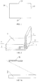
- FIG. 2 is a three-dimensional schematic diagram of a backlight unit according to an embodiment of the present disclosure.
- the backlight unit includes a light guide plate 2 and a rubber frame 3.
- the light guide plate 2 includes a main body portion 21, and the main body portion 21 is of a cuboid flat plate structure and includes a first main surface and a second main surface which are opposite to each other and four lateral surfaces connected with the first main surface and the second main surface.
- four lateral surfaces of the main body portion 21 one lateral surface is used as a first lateral surface portion and is set as a light incident side; and the other three lateral surfaces constitute a second lateral surface portion.
- the light guide plate 2 further includes an extending portion 22 extending outwards from at least one lateral surface (only one lateral surface is shown in FIG. 2 ) except for the light incident side of the main body portion 21. It can be known from FIG. 2 that a thickness of the extending portion 22 is smaller than that of the main body portion 21. As described above, the extending portion also can extend outwards from three lateral surfaces which constitute the second lateral surface portion, the embodiment of the present disclosure is not specially limited hereto, and the extending portion can be arranged at the position of at least one part of the second lateral surface portion. With further reference to FIG.
- the extending portion 22 covers the upper side of the rubber frame 3, i.e., the rubber frame 3 is overlapped with the extending portion 22 in the thickness direction of the main body portion 21 of the light guide plate and the rubber frame 3 and the main body portion 21 are at least partially oppositely arranged at an interval.
- the extending portion weakens the phenomenon of edge bright lines at a large viewing angle by moving the edge of the light guide plate outwards.
- the main body portion 21 of the light guide plate shown in FIG. 2 is of a cuboid flat plate structure, and as described above, the main body portion also can be of one of other structures.
- the extending portion 22 is of a flat plate structure extending outwards along one main surface of the main body portion 21, and as described above, the extending portion also can be of any other structure, e.g., a wedged plate structure.
- the thickness of the extending portion 22 is smaller than that of the main body portion 21.
- the cross section of the rubber frame 3 shown in FIG. 2 is of a rectangular shape, but the structure of the rubber frame is not limited hereto.
- the cross section of the rubber frame 3 also can be of a square, round, trapezoid or polygon shape or any other irregular shape.
- the rubber frame 3 for example, is prepared from a non-metallic material, and for example, is prepared from materials of rubber, resin and the like.
- the backlight unit further can include some other optional parts.
- FIG. 2 also shows other optional parts in the backlight unit, which include a backplane 1 and a reflective sheet 4, and shows a mutual arrangement relationship among the backplane 1, the reflective sheet 4, the light guide plate 2 and the rubber frame 3.
- both the light guide plate 2 and the rubber frame 3 are arranged at one side of the backplane 1.
- the reflective sheet 4 is further arranged between the light guide plate 2 and the backplane 1.
- the rubber frame 3 further includes a portion arranged oppositely to the reflective sheet 4.
- An arrangement mode of a light source e.g., Light-Emitting Diode (LED) light bar, can adopt various arrangement modes in the prior art.
- LED Light-Emitting Diode
- the LED light bar can be arranged on the rubber frame, and for example, a light emergent surface of the LED faces the light incident side of the light guide plate. Most of light emitted by the light source is reflected by the reflective sheet and is emitted outwards from a light emergent side of the light guide plate, which is, according to the invention, the first main surface. Simultaneously, part of light can be leaked out of other lateral surfaces of the light guide plate.
- Such backlight unit structure shown in FIG. 2 can effectively relieve the phenomenon of the edge bright lines at a large viewing angle by moving the edge of the light guide plate outwards.
- FIG. 3a and FIG. 3b are schematic diagrams that the extending portion can relieve the phenomenon of the edge bright lines at a large viewing angle.
- a black matrix 6 in FIG. 3a and FIG. 3b is arranged in an upper substrate (not shown in drawings) of the display device, and for example, is deposited at a lightproof portion among Red, Green and Blue (RGB) color filters.
- the black matrix is mainly used for preventing leakage of background light, improving the display contrast and the like.
- the light guide plate does not include the extending portion, the light at the edge of the light guide plate can enter human eyes at a certain angle via the edge of the black matrix 6.
- the edge of the light guide plate is moved outwards, and thus, an angle that the light at the outer edge of the extending portion enters the human eyes via the black matrix 6 is obviously decreased, i.e., the phenomenon of the edge bright lines at a large viewing angle is relieved.
- the phenomenon of the edge bright lines at a large viewing angle can be effectively weakened and even eliminated.
- the viewing angle herein can be an angle between a connecting line (dotted lines in FIGS. 3a and 3b ) of the inside edge of the black matrix closest to the extending portion in the display device and the outside edge of the extending portion and a straight line in parallel to the light guide plate.
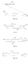
- FIG. 4 is a side-view schematic diagram of a light guide plate structure of the embodiment of the present disclosure.
- a main body portion 21 of a light guide plate 2 includes a first main surface 23, a second main surface 24 which are opposite to each other and a lateral surface.
- the lateral surface includes a first lateral surface portion 28 used as a light incident side and a second lateral surface portion 25 outside the first lateral surface portion.
- the first main surface 23 is the light emergent side, and the extending portion 22 extends outwards from the second lateral surface portion 25 of the main body portion, is close to the first main surface 23 and for example, is flush with the first main surface 23.
- FIG. 5 is a side-view schematic diagram of a light guide plate not part of the invention.
- a main body portion 21 of the light guide plate 2 includes a first main surface 23 and a second main surface 24 which are opposite to each other and a lateral surface.
- the lateral surface includes a first lateral surface portion 28 used as a light incident side and a second lateral surface portion 25 outside the first lateral surface portion 28.
- the first main surface 23 is the light emergent side
- the extending portion 22 extends outwards from the second lateral surface portion 25 of the main body portion, is close to the second main surface 24 and for example, is flush with the second main surface 24.
- a rubber frame is completely positioned at one side of an extending portion of a light guide plate, and the extending portion is basically completely overlapped with the rubber frame in the thickness direction.
- FIGS. 6a to 6c are schematic diagrams of an arrangement mode of the light guide plate and the rubber frame of the embodiment of the present disclosure.
- FIG. 6a is a side-view schematic diagram of arrangement of the light guide plate and the rubber frame of the embodiment of the present disclosure;
- FIG. 6b is a side-view schematic diagram of the light guide plate in FIG. 6a ;
- FIG. 6c is a side-view schematic diagram of the rubber frame in FIG. 6a .
- a main body portion 21 of the light guide plate 2 includes a first main surface 23 and a second main surface 24 which are opposite to each other and a lateral surface connected with the first main surface 23 and the second main surface 24.
- the lateral surface includes a first lateral surface portion used as a light incident side and a second lateral surface portion 25 outside the first lateral surface portion.
- one first lateral surface is the light incident side
- the other three lateral surfaces constitute the second lateral surface portion, and only the arrangement case of an extending portion of one lateral surface is shown in the drawings.
- the first main surface 23 is a light emergent side, and the extending portion 22 extends outwards from the second lateral surface portion 25 of the main body portion 21, is close to the first main surface 23 and according to the invention it is flush with the first main surface 23.
- the rubber frame 3 includes a first surface 31 and a second surface 32 which are opposite to each other and a surface 33 which is connected with the first surface 31 and the second surface 32 and faces the second lateral surface portion.
- the extending portion 22 and the first surface 31 are opposite to each other and are arranged at an interval.
- a rubber frame further includes a supporting portion.
- FIG. 7a is a three-dimensional schematic diagram of a backlight unit of which the rubber frame includes the supporting portion according to the embodiment of the present disclosure
- FIG. 7b is a side-view schematic diagram of an arrangement mode of the light guide plate and the rubber frame in FIG. 7a .
- the side of the rubber frame 3 which faces away from a second lateral surface 33, includes the flat-shaped supporting portion 34; and the supporting portion 34 is connected with a second surface 32 and a first surface 31 and extends towards the direction far away from the second surface 32.
- an opposite arrangement mode of the first surface 31, the second surface 32 and the surfaces 33 connected with the first surface 31 and the second surface 32 of the rubber frame 3 and the light guide plate 2 is, for example, the same as those in the embodiments above, can refer to the previous description and is not repeated herein.
- the edge of the light guide plate is moved outwards so as to effectively weaken the phenomenon of edge bright lines at a large viewing angle, and the supporting portion of the rubber frame further improves stability of the backlight unit structure.
- FIG. 7a further shows a backplane and a reflective sheet.
- one side of the supporting portion 34, which is far away from the light guide plate, and the backplane are oppositely arranged at an interval.
- one side of the supporting portion 34, which is far away from the light guide plate also can be attached to the backplane 1 so as to improve stability of the backlight unit structure and protect optical elements in the backlight unit better.
- the reflective sheet 4 is also arranged between a second main surface 24 of the main body portion of the light guide plate and the backplane.
- the reflective sheet 4 and a third lateral surface of the rubber frame for example, also at least partially face each other and arranged at an interval so as to improve stability of the backlight unit structure.
- a thickness ratio of an extending portion and a main body portion can be further regulated.
- the extending portion has an effect of moving the edge of a light guide plate outwards. Therefore, edge bright lines are difficult to observe at the outwards moved edge of the light guide plate at a large viewing angle; but the edge of the light guide plate, which is not moved outwards, still has bright lines at a large viewing angle. Thus from this perspective, a greater thickness ratio of the extending portion and the main body portion is better.
- the rubber frame and the edge of the light guide plate have portions arranged to face each other, so that the rubber frame can fix the light guide plate from the outside of the light guide plate.
- a smaller thickness of the extending portion is better so as to enable the entire backlight unit to be more stable in structure. Therefore, a greater thickness ratio of the extending portion and the main body portion is also not better really, or the light guide plate cannot be effectively fixed.
- the thickness of the extending portion is one third to five sixths of the total thickness of the light guide plate, and for example, the thickness of the extending portion is one second to second thirds of the total thickness of the light guide plate, so that the phenomenon of the edge bright lines in a large viewing angle can be effectively relieved on the premise of ensuring structural stability of the backlight unit.
- a distance from one side of an extending portion, which is far away from a main body portion, to the main body portion can be defined.
- an outwards moving quantity of the light guide plate is limited to a certain extent.
- the edge of the light guide plate only needs to extend to a position where the bright lines at a large viewing angle can be eliminated.
- the distance H from one side of the extending portion, which is far away from the main body portion, to the main body portion is not smaller than 0.5 cm and for example, is not smaller than 1.5 cm.
- those skilled in the art can set the maximum value of H according to the space limitation of the backlight unit, which is not specially limited herein.
- the shape of an extending portion can be set as a wedge shape.
- the extending portion 22 is of a wedged structure of which the thickness is gradually decreased from the side close to a main body portion 21 to the side far away from the main body portion 21.
- FIG. 8 shows a moving direction of a light path after parallel light is irradiated to the wedged structure of the light guide plate.
- such wedged structure can enable the parallel light entering from one side of the light guide plate to be inclined upwards after passing through the wedged structure and reduce the light irradiated to a rubber frame so as to effectively reduce light leakage at the edge of the light guide plate and relieve the phenomenon of edge bright lines at a large viewing angle.
- a wedge angle of the wedged extending portion can be further defined, and for example, the wedge angle is not greater than 30 degrees so as to further reduce a light leakage quantity at the position of a wedge surface.
- the wedge angle means an angle between a plane where a wedged surface 29 is positioned and a plane where a second main surface 24 is positioned.
- second lateral surface portions outside a light incident side of a main body portion of a light guide plate for example, the other three lateral surfaces of the main body portion with a cuboid structure, all include extending portions so as to relieve the phenomenon of edge bright lines at a large viewing angle better.
- edge bright lines in a large viewing angle can be weakened or eliminated by enabling light laterally leaked out of a light guide plate to be diffusely reflected.
- surfaces of the light guide plate and a rubber frame, which are mutually oppositely arranged can be coated with diffuse reflection coatings, so that parallel light leaked out of the light guide plate is diffusely reflected and brightness of the edge bright lines at a large viewing angle is reduced.
- a diffuse reflection paint including polyvinyl alcohol and barium sulfate is sprayed to the surfaces of the light guide plate and the rubber frame, which are mutually oppositely arranged, to prepare the diffuse reflection coatings.
- a nano diffuse reflection paint also can be sprayed to the surfaces of the light guide plate and the rubber frame, which are mutually oppositely arranged, to prepare the diffuse reflection coatings.
- the surface of the light guide plate, which is arranged oppositely to the rubber frame is coated with the diffuse reflection coating, or the surface of the rubber frame, which is arranged oppositely to the light guide plate, is coated with the diffuse reflection coating, or the surfaces of the light guide plate and the rubber frame, which are mutually oppositely arranged, arc respectively coated with the diffuse reflection coatings, so that the light is diffusely reflected via the diffuse reflection coatings before or after being leaked out of the lateral surface of the light guide plate, thereby further reducing brightness of the edge bright lines and improving a display effect.
- a layer of light adsorption film can be arranged on the surface of a rubber frame, which is opposite to a light guide plate.
- the layer of light adsorption film can adsorb light leaked out of the lateral surface of the light guide plate so as to eliminate the basic reason of generating edge bright lines.
- the light adsorption film for example, needs to have a certain heat resistance so as to ensure that when the temperature of a backlight unit is risen, the light adsorption film cannot be decomposed or changed.
- the light adsorption film is a black light adsorption film prepared from a high polymer material, and for example, the light adsorption film can be adhered to the surface of the rubber frame, which is opposite to the light guide plate, so as to sufficiently adsorb light leaked out of the edge of the light guide plate and relieve the phenomenon of the edge bright lines at a large viewing angle.
- FIG. 9 shows an extending portion and rubber frame mutually-clamped structure.
- the extending portion of the light guide plate includes a first portion 26 close to a main body portion and a second portion 27 far away from the main body portion.
- One side of the first portion 26 is connected with the main body portion, and the other side of the first portion 26 is connected with one side of the second portion 27.
- a thickness of the second portion 27 is greater than that of the first portion 26, and the second portion 27 is convex towards a first surface of the rubber frame to form a wedged convex portion.
- a first groove 35 matched with the wedged convex portion is formed on the first surface of the rubber frame 3.
- the first groove 35 can be formed by machining in a direction from the first surface 31 to the second surface 32 in the embodiments above, and also can be directly formed by a die.
- the wedged convex portion of the second portion 27 is embedded into the first groove 35 and is arranged at an interval oppositely to each surface of the first groove 35.
- the extending portion and the rubber frame also can be of other mutually clamped structures, and the present disclosure is not limited to the structure above. By adopting such the extending portion and rubber frame mutually-clamped structure, when the edge bright lines are relieved, structural stability of the backlight unit can be improved.
- An embodiment of the present disclosure further provides a display device including the backlight unit as mentioned above.
- the display device has a better display effect.
- words such as “first”, “second” and the like do not request or denote any relationship or order between entities or operations, but rather are used for distinguishing one entity or operation from another entity or operation.
- Words such as “include” and “comprise” are open-ended expressions, not exclusive of the case that the included processes, methods and objects further have other elements.
- words such as “up”, “down” and the like denote direction or position relationships based on the accompanying drawings, and are only used for facilitating describing the present disclosure and simplifying description, rather than indicate or denote that the indicated apparatus or elements shall have specific directions and be constructed and operated in specific directions, and thus, it should not be understood as limitation to the present disclosure.
- words such as “installing”, “connected” and “connecting” should be understood in general, for example, can be fixed connection, also can be detachable connection, or integrated connection, can be mechanical connection, also can be electrical connection, can be direct connection, also can be indirect connection by an intermediate medium, and also can be communication inside two elements.
- installing can be fixed connection, also can be detachable connection, or integrated connection, can be mechanical connection, also can be electrical connection, can be direct connection, also can be indirect connection by an intermediate medium, and also can be communication inside two elements.
Landscapes
- Physics & Mathematics (AREA)
- General Physics & Mathematics (AREA)
- Optics & Photonics (AREA)
- Planar Illumination Modules (AREA)
- Illuminated Signs And Luminous Advertising (AREA)
Description
- The present invention relates to an edge-lit backlight unit and a display device.
- In a backlight unit structure, generally, a rubber frame with a certain width can be relatively arranged at the edge outside a light guide plate. Due to structural space limitation of the rubber frame and the light guide plate, the edge of the light guide plate is close to, for example, a visible region of a display device, so that the backlight unit has edge bright lines at a large viewing angle. Currently, a narrow frame display has become a development tendency. In a narrow frame structure, the edge of the light guide plate is closer to the visible region, so that the problem of the edge bright lines at a large viewing angle is more serious.
-
CN 203 787 042 U discloses a fixing structure for a display screen rubber frame and a light guiding plate. The fixing structure comprises a base plate, the rubber frame and the light guiding plate, wherein the rubber frame is made of a flexible material, the periphery of the inner side of the rubber frame is provided with a plurality of connecting grooves, the peripheral side of the light guiding plate is provided with a plurality of clamping blocks corresponding to the connecting grooves in a protruding mode, and the clamping blocks are integrally connected with the light guiding plate. Each clamping block is correspondingly clamped and connected into the corresponding connecting groove, an elastic cover plate is arranged at the top of each connecting groove and integrally connected with the rubber frame, one end of the elastic cover plate is fixedly connected onto the top of each connecting grooves, and the other end of the elastic cover plate is pressed on the tops of the clamping blocks. An ejection block is arranged at the bottom of each connecting groove and integrally connected with the rubber frame, and the bottoms of the clamping blocks are pressed on the ejection blocks. -
US 2003/128307 A1 discloses a liquid crystal display device (LCD), in which thin-film spacers having resiliency are arranged in the inside of a metal frame for holding a LCD panel. The spacer includes protrusions and the LCD panel is fixed by utilizing the resiliency of the protrusions. Further, a resin material having high reflectance is used as a material of the spacer. - It is an object of the present invention to provide an edge-lit backlight unit and a display device, which can solve the problem of edge bright lines at a larger view angle.
- The object is achieved by the features of the respective independent claims. Further embodiments are defined in the corresponding dependent claims.
- In order to clearly illustrate the technical solution of the embodiments of the disclosure, the drawings of the embodiments will be briefly described in the following; the described drawings are only related to some embodiments of the disclosure, but not intended to define the disclosure.
-
FIG. 1 is a plan schematic diagram of a light guide plate which is of a cuboid structure; -
FIG. 2 is a three-dimensional schematic diagram of a backlight unit of an embodiment of the present disclosure; -
FIG. 3a is a schematic diagram of a generation principle of edge bright lines of a light guide plate at a large viewing angle; -
FIG. 3b is a schematic diagram that a light guide plate structure of an embodiment of the present disclosure relieves edge bright lines at a large viewing angle; -
FIG. 4 is a side-view schematic diagram of a light guide plate structure of an embodiment of the present disclosure; -
FIG. 5 is a side-view schematic diagram of another light guide plate structure not part of the invention; -
FIGS. 6a to 6c are side-view schematic diagrams of an arrangement mode of a light guide plate and a rubber frame of an embodiment of the present disclosure; -
FIG. 7a is a three-dimensional schematic diagram of a backlight unit with another rubber frame structure of an embodiment of the present disclosure; -
FIG. 7b is a side-view schematic diagram of an arrangement mode of the light guide plate and the rubber frame inFIG. 7a ; -
FIG. 8 is a side-view schematic diagram of a light guide plate with a wedged extending portion of an embodiment of the present disclosure; -
FIG. 9 is a side-view schematic diagram of an extending portion and rubber frame mutually-clamped structure of an embodiment of the present disclosure. - In order to make objects, technical solutions and advantages of the embodiments of the disclosure apparent, the technical solutions of the embodiment of the disclosure will be described in a clearly and fully understandable way in connection with the drawings related to the embodiments of the disclosure. It is obvious that the described embodiments are just a part but not all of the embodiments of the disclosure. Based on the described embodiments of the disclosure herein, those skilled in the art can obtain other embodiment(s), without any inventive work, which should be within the scope of the disclosure.
- In a display device using an edge-lit backlight unit, the backlight unit, for example, can include a backplane and a reflective sheet and a light guide plate which are sequentially arranged at one side of the backplane. Optical films are arranged at one side of the light guide plate, which is far away from the backplane, and the optical films include, for example, a diffusion sheet, a lower prism and an upper prism. A shading adhesive tape, for example, can also be arranged at one side of the optical film. A rubber frame with a certain thickness is, for example, arranged around the outer edge of the backplane so as to fix various optical parts from the outside. The rubber frame is generally made of a non-metallic material, e.g., materials of rubber, resin and the like. A light source is arranged at the light incident side of the light guide plate. After light emitted by the light source passes through the light guide plate, part of the light will be leaked out of the lateral surface outside the light incident side of the light guide plate, and the leaked light is reflected after being irradiated to the rubber frame which is arranged at an interval with the light guide plate, so that a light centralization region which is visible in a large viewing angle is formed at the position of the interval between the light guide plate and the rubber frame, i.e., edge bright lines are generated, and a display effect of the display device is influenced.
- An exemplary edge-lit backlight unit includes light guide plate and a rubber frame, wherein the light guide plate includes a main body portion, the main body portion is of a flat plate structure and includes a first main surface and a second main surface which are opposite to each other and a lateral surface, and the lateral surface includes a first lateral surface portion used as a light incident side and a second lateral surface portion outside the first lateral surface portion; the light guide plate further includes an extending portion extending outwards from the second lateral surface portion of the main body portion; and at least a part of the rubber frame and the second lateral surface portion of the main body portion are oppositely arranged at an interval and the at least a part of the rubber frame is at least partially overlapped with the extending portion in the thickness direction of the main body portion. The extending portion has an effect of moving an edge portion of the light guide plate outwards so as to weaken or eliminate bright lines at a large viewing angle. Such backlight unit of the embodiment of the present disclosure has the advantages of simplicity for manufacturing, easiness for implementation, convenience in assembling and the like.
-
FIG. 1 is a plan schematic diagram of a light guide plate which is of a cuboid structure. With reference toFIG. 1 , for the light guide plate with the cuboid structure, for example, a firstlateral surface portion 28 is a light incident side, and the other three lateral surfaces, for example, can be named as secondlateral surface portions 25. Extending portions, for example, are formed in a mode that three lateral surfaces extend outwards, i.e., three lateral surfaces except for the light incident side all include the extending portions. For example, the extending portions also can be formed in a mode that two or one of the lateral surfaces extends outwards, or can be formed in a mode that one part of one of the lateral surfaces extends outwards. - The main body portion of the light guide plate of the embodiment of the present disclosure also can be of any other shape, for example, the main body portion only includes two lateral surfaces or includes a plurality of lateral surfaces, for example, at least one lateral surface is set as the light incident side, and other lateral surfaces outside the light incident side form the second lateral surface portions. Moreover, the extending portion, for example, can be of a shape of a flat plate or a wedged plate or any other regular or irregular shape, but the extending portion needs to be guaranteed to be at least partially overlapped with the rubber frame in the thickness direction of the main body portion.
-
FIG. 2 is a three-dimensional schematic diagram of a backlight unit according to an embodiment of the present disclosure. With reference toFIG. 2 , the backlight unit includes alight guide plate 2 and arubber frame 3. Thelight guide plate 2 includes amain body portion 21, and themain body portion 21 is of a cuboid flat plate structure and includes a first main surface and a second main surface which are opposite to each other and four lateral surfaces connected with the first main surface and the second main surface. In four lateral surfaces of themain body portion 21, one lateral surface is used as a first lateral surface portion and is set as a light incident side; and the other three lateral surfaces constitute a second lateral surface portion. With reference toFIG. 2 , for example, thelight guide plate 2 further includes an extendingportion 22 extending outwards from at least one lateral surface (only one lateral surface is shown inFIG. 2 ) except for the light incident side of themain body portion 21. It can be known fromFIG. 2 that a thickness of the extendingportion 22 is smaller than that of themain body portion 21. As described above, the extending portion also can extend outwards from three lateral surfaces which constitute the second lateral surface portion, the embodiment of the present disclosure is not specially limited hereto, and the extending portion can be arranged at the position of at least one part of the second lateral surface portion. With further reference toFIG. 2 , the extendingportion 22 covers the upper side of therubber frame 3, i.e., therubber frame 3 is overlapped with the extendingportion 22 in the thickness direction of themain body portion 21 of the light guide plate and therubber frame 3 and themain body portion 21 are at least partially oppositely arranged at an interval. The extending portion weakens the phenomenon of edge bright lines at a large viewing angle by moving the edge of the light guide plate outwards. - The
main body portion 21 of the light guide plate shown inFIG. 2 is of a cuboid flat plate structure, and as described above, the main body portion also can be of one of other structures. The extendingportion 22 is of a flat plate structure extending outwards along one main surface of themain body portion 21, and as described above, the extending portion also can be of any other structure, e.g., a wedged plate structure. The thickness of the extendingportion 22 is smaller than that of themain body portion 21. - The cross section of the
rubber frame 3 shown inFIG. 2 is of a rectangular shape, but the structure of the rubber frame is not limited hereto. For example, the cross section of therubber frame 3 also can be of a square, round, trapezoid or polygon shape or any other irregular shape. - The
rubber frame 3, for example, is prepared from a non-metallic material, and for example, is prepared from materials of rubber, resin and the like. - In some embodiments, the backlight unit further can include some other optional parts. For example,
FIG. 2 also shows other optional parts in the backlight unit, which include abackplane 1 and areflective sheet 4, and shows a mutual arrangement relationship among thebackplane 1, thereflective sheet 4, thelight guide plate 2 and therubber frame 3. With reference toFIG. 2 , both thelight guide plate 2 and therubber frame 3 are arranged at one side of thebackplane 1. Thereflective sheet 4 is further arranged between thelight guide plate 2 and thebackplane 1. Therubber frame 3 further includes a portion arranged oppositely to thereflective sheet 4. An arrangement mode of a light source, e.g., Light-Emitting Diode (LED) light bar, can adopt various arrangement modes in the prior art. For example, the LED light bar can be arranged on the rubber frame, and for example, a light emergent surface of the LED faces the light incident side of the light guide plate. Most of light emitted by the light source is reflected by the reflective sheet and is emitted outwards from a light emergent side of the light guide plate, which is, according to the invention, the first main surface. Simultaneously, part of light can be leaked out of other lateral surfaces of the light guide plate. Such backlight unit structure shown inFIG. 2 can effectively relieve the phenomenon of the edge bright lines at a large viewing angle by moving the edge of the light guide plate outwards. -
FIG. 3a andFIG. 3b are schematic diagrams that the extending portion can relieve the phenomenon of the edge bright lines at a large viewing angle. Ablack matrix 6 inFIG. 3a andFIG. 3b is arranged in an upper substrate (not shown in drawings) of the display device, and for example, is deposited at a lightproof portion among Red, Green and Blue (RGB) color filters. The black matrix is mainly used for preventing leakage of background light, improving the display contrast and the like. With reference toFIG. 3a , when the light guide plate does not include the extending portion, the light at the edge of the light guide plate can enter human eyes at a certain angle via the edge of theblack matrix 6. After the light guide plate is provided with the extending portion, the edge of the light guide plate is moved outwards, and thus, an angle that the light at the outer edge of the extending portion enters the human eyes via theblack matrix 6 is obviously decreased, i.e., the phenomenon of the edge bright lines at a large viewing angle is relieved. It should be noted that due to the small viewing angle of the edge bright lines of the light guide plate, after the edge of the light guide plate is moved outwards by the extending portion, the phenomenon of the edge bright lines at a large viewing angle can be effectively weakened and even eliminated. For example, in a sectional view perpendicular to the extending direction of the extending portion, the viewing angle herein can be an angle between a connecting line (dotted lines inFIGS. 3a and3b ) of the inside edge of the black matrix closest to the extending portion in the display device and the outside edge of the extending portion and a straight line in parallel to the light guide plate. - In one embodiment, an extending portion is close to a light incident side.
FIG. 4 is a side-view schematic diagram of a light guide plate structure of the embodiment of the present disclosure. With reference toFIG. 4 , amain body portion 21 of alight guide plate 2 includes a firstmain surface 23, a secondmain surface 24 which are opposite to each other and a lateral surface. The lateral surface includes a firstlateral surface portion 28 used as a light incident side and a secondlateral surface portion 25 outside the first lateral surface portion. The firstmain surface 23 is the light emergent side, and the extendingportion 22 extends outwards from the secondlateral surface portion 25 of the main body portion, is close to the firstmain surface 23 and for example, is flush with the firstmain surface 23. By the extending portion, the edge of the light guide plate, which is close to a visible region portion, is moved outwards, so that the phenomenon of edge bright lines at a large viewing angle is relieved and the light guide plate is simple to manufacture. -
FIG. 5 is a side-view schematic diagram of a light guide plate not part of the invention. With reference toFIG. 5 , amain body portion 21 of thelight guide plate 2 includes a firstmain surface 23 and a secondmain surface 24 which are opposite to each other and a lateral surface. The lateral surface includes a firstlateral surface portion 28 used as a light incident side and a secondlateral surface portion 25 outside the firstlateral surface portion 28. The firstmain surface 23 is the light emergent side, and the extendingportion 22 extends outwards from the secondlateral surface portion 25 of the main body portion, is close to the secondmain surface 24 and for example, is flush with the secondmain surface 24. By the extending portion, the edge of the light guide plate, which is far away from a visible region portion, is moved outwards, so that the phenomenon of edge bright lines at a large viewing angle is relieved and a preparation process of the light guide plate is simplified. - In one embodiment, a rubber frame is completely positioned at one side of an extending portion of a light guide plate, and the extending portion is basically completely overlapped with the rubber frame in the thickness direction.
FIGS. 6a to 6c are schematic diagrams of an arrangement mode of the light guide plate and the rubber frame of the embodiment of the present disclosure.FIG. 6a is a side-view schematic diagram of arrangement of the light guide plate and the rubber frame of the embodiment of the present disclosure;FIG. 6b is a side-view schematic diagram of the light guide plate inFIG. 6a ; andFIG. 6c is a side-view schematic diagram of the rubber frame inFIG. 6a . - With reference to
FIGS. 6a to 6c , amain body portion 21 of thelight guide plate 2 includes a firstmain surface 23 and a secondmain surface 24 which are opposite to each other and a lateral surface connected with the firstmain surface 23 and the secondmain surface 24. The lateral surface includes a first lateral surface portion used as a light incident side and a secondlateral surface portion 25 outside the first lateral surface portion. For example, for the case that the main body portion of the light guide plate is of a flat plate cuboid structure, one first lateral surface is the light incident side, the other three lateral surfaces constitute the second lateral surface portion, and only the arrangement case of an extending portion of one lateral surface is shown in the drawings. The firstmain surface 23 is a light emergent side, and the extendingportion 22 extends outwards from the secondlateral surface portion 25 of themain body portion 21, is close to the firstmain surface 23 and according to the invention it is flush with the firstmain surface 23. Therubber frame 3 includes afirst surface 31 and asecond surface 32 which are opposite to each other and asurface 33 which is connected with thefirst surface 31 and thesecond surface 32 and faces the second lateral surface portion. The extendingportion 22 and thefirst surface 31 are opposite to each other and are arranged at an interval. By the extending portion, the edge of the light guide plate, which is close to one side of the rubber frame, is moved outwards, so that the phenomenon of bright lines at a large viewing angle is effectively weakened. - In one embodiment, a rubber frame further includes a supporting portion.
FIG. 7a is a three-dimensional schematic diagram of a backlight unit of which the rubber frame includes the supporting portion according to the embodiment of the present disclosure; andFIG. 7b is a side-view schematic diagram of an arrangement mode of the light guide plate and the rubber frame inFIG. 7a . With reference toFIGS. 7a and 7b , the side of therubber frame 3, which faces away from a secondlateral surface 33, includes the flat-shaped supportingportion 34; and the supportingportion 34 is connected with asecond surface 32 and afirst surface 31 and extends towards the direction far away from thesecond surface 32. At least part of the supportingportion 34 and one side of the extendingportion 22, which is far away from themain body portion 21, are oppositely arranged at an interval, i.e., one part of the flat-shaped supportingportion 34 and the outer edge of the extendingportion 22 are oppositely arranged at an interval. - In the embodiment, an opposite arrangement mode of the
first surface 31, thesecond surface 32 and thesurfaces 33 connected with thefirst surface 31 and thesecond surface 32 of therubber frame 3 and thelight guide plate 2 is, for example, the same as those in the embodiments above, can refer to the previous description and is not repeated herein. By the extending portion, the edge of the light guide plate is moved outwards so as to effectively weaken the phenomenon of edge bright lines at a large viewing angle, and the supporting portion of the rubber frame further improves stability of the backlight unit structure. - It should be noted that
FIG. 7a further shows a backplane and a reflective sheet. With further reference toFIG. 7a , one side of the supportingportion 34, which is far away from the light guide plate, and the backplane are oppositely arranged at an interval. For example, one side of the supportingportion 34, which is far away from the light guide plate, also can be attached to thebackplane 1 so as to improve stability of the backlight unit structure and protect optical elements in the backlight unit better. Thereflective sheet 4 is also arranged between a secondmain surface 24 of the main body portion of the light guide plate and the backplane. Thereflective sheet 4 and a third lateral surface of the rubber frame, for example, also at least partially face each other and arranged at an interval so as to improve stability of the backlight unit structure. - In one embodiment, a thickness ratio of an extending portion and a main body portion can be further regulated. In one aspect, the extending portion has an effect of moving the edge of a light guide plate outwards. Therefore, edge bright lines are difficult to observe at the outwards moved edge of the light guide plate at a large viewing angle; but the edge of the light guide plate, which is not moved outwards, still has bright lines at a large viewing angle. Thus from this perspective, a greater thickness ratio of the extending portion and the main body portion is better. In another aspect, with reference to the previous description, the rubber frame and the edge of the light guide plate have portions arranged to face each other, so that the rubber frame can fix the light guide plate from the outside of the light guide plate. In other words, from the perspective of ensuring a fixing effect of the rubber frame on optical parts, e.g., the light guide plate and the like, a smaller thickness of the extending portion is better so as to enable the entire backlight unit to be more stable in structure. Therefore, a greater thickness ratio of the extending portion and the main body portion is also not better really, or the light guide plate cannot be effectively fixed. Influence of variations of the thickness of the extending portion on the edge bright lines and structural stability of the backlight unit is comprehensively considered, for example, the thickness of the extending portion is one third to five sixths of the total thickness of the light guide plate, and for example, the thickness of the extending portion is one second to second thirds of the total thickness of the light guide plate, so that the phenomenon of the edge bright lines in a large viewing angle can be effectively relieved on the premise of ensuring structural stability of the backlight unit.
- In one embodiment, a distance from one side of an extending portion, which is far away from a main body portion, to the main body portion can be defined. In one aspect, the longer the distance between one side of the extending portion, which is far away from the main body portion, and the main body portion is, the farther the edge of a light guide plate is moved outwards, and the less obvious the phenomenon of edge bright lines at a large viewing angle is. In another aspect, due to structural limitation of a backlight unit, an outwards moving quantity of the light guide plate is limited to a certain extent. Moreover, in the case of allowance of a structural space of the backlight unit, the edge of the light guide plate only needs to extend to a position where the bright lines at a large viewing angle can be eliminated. For example, the distance H from one side of the extending portion, which is far away from the main body portion, to the main body portion is not smaller than 0.5 cm and for example, is not smaller than 1.5 cm. Meanwhile, those skilled in the art can set the maximum value of H according to the space limitation of the backlight unit, which is not specially limited herein. By setting the distance from one side of the extending portion, which is far away from the main body portion, to the main body portion, the phenomenon of the edge bright lines at a large viewing angle can be effectively relieved and even eliminated.
- In one embodiment, the shape of an extending portion can be set as a wedge shape. With reference to
FIG. 8 , the extendingportion 22 is of a wedged structure of which the thickness is gradually decreased from the side close to amain body portion 21 to the side far away from themain body portion 21.FIG. 8 shows a moving direction of a light path after parallel light is irradiated to the wedged structure of the light guide plate. Namely, such wedged structure can enable the parallel light entering from one side of the light guide plate to be inclined upwards after passing through the wedged structure and reduce the light irradiated to a rubber frame so as to effectively reduce light leakage at the edge of the light guide plate and relieve the phenomenon of edge bright lines at a large viewing angle. - In the embodiment, for example, a wedge angle of the wedged extending portion can be further defined, and for example, the wedge angle is not greater than 30 degrees so as to further reduce a light leakage quantity at the position of a wedge surface. The wedge angle means an angle between a plane where a wedged
surface 29 is positioned and a plane where a secondmain surface 24 is positioned. - In one embodiment, second lateral surface portions outside a light incident side of a main body portion of a light guide plate, for example, the other three lateral surfaces of the main body portion with a cuboid structure, all include extending portions so as to relieve the phenomenon of edge bright lines at a large viewing angle better.
- In one embodiment, edge bright lines in a large viewing angle can be weakened or eliminated by enabling light laterally leaked out of a light guide plate to be diffusely reflected. For example, surfaces of the light guide plate and a rubber frame, which are mutually oppositely arranged, can be coated with diffuse reflection coatings, so that parallel light leaked out of the light guide plate is diffusely reflected and brightness of the edge bright lines at a large viewing angle is reduced. For example, a diffuse reflection paint including polyvinyl alcohol and barium sulfate is sprayed to the surfaces of the light guide plate and the rubber frame, which are mutually oppositely arranged, to prepare the diffuse reflection coatings. For example, a nano diffuse reflection paint also can be sprayed to the surfaces of the light guide plate and the rubber frame, which are mutually oppositely arranged, to prepare the diffuse reflection coatings. For example, the surface of the light guide plate, which is arranged oppositely to the rubber frame, is coated with the diffuse reflection coating, or the surface of the rubber frame, which is arranged oppositely to the light guide plate, is coated with the diffuse reflection coating, or the surfaces of the light guide plate and the rubber frame, which are mutually oppositely arranged, arc respectively coated with the diffuse reflection coatings, so that the light is diffusely reflected via the diffuse reflection coatings before or after being leaked out of the lateral surface of the light guide plate, thereby further reducing brightness of the edge bright lines and improving a display effect.
- In one embodiment, a layer of light adsorption film can be arranged on the surface of a rubber frame, which is opposite to a light guide plate. The layer of light adsorption film can adsorb light leaked out of the lateral surface of the light guide plate so as to eliminate the basic reason of generating edge bright lines. The light adsorption film, for example, needs to have a certain heat resistance so as to ensure that when the temperature of a backlight unit is risen, the light adsorption film cannot be decomposed or changed. For example, the light adsorption film is a black light adsorption film prepared from a high polymer material, and for example, the light adsorption film can be adhered to the surface of the rubber frame, which is opposite to the light guide plate, so as to sufficiently adsorb light leaked out of the edge of the light guide plate and relieve the phenomenon of the edge bright lines at a large viewing angle.
- In one embodiment, the outside of an extending portion of a light guide plate and a rubber frame can be designed into mutually clamped structures.
FIG. 9 shows an extending portion and rubber frame mutually-clamped structure. With reference toFIG. 9 , the extending portion of the light guide plate includes afirst portion 26 close to a main body portion and asecond portion 27 far away from the main body portion. One side of thefirst portion 26 is connected with the main body portion, and the other side of thefirst portion 26 is connected with one side of thesecond portion 27. A thickness of thesecond portion 27 is greater than that of thefirst portion 26, and thesecond portion 27 is convex towards a first surface of the rubber frame to form a wedged convex portion. Afirst groove 35 matched with the wedged convex portion is formed on the first surface of therubber frame 3. For example, thefirst groove 35 can be formed by machining in a direction from thefirst surface 31 to thesecond surface 32 in the embodiments above, and also can be directly formed by a die. In a backlight unit, the wedged convex portion of thesecond portion 27 is embedded into thefirst groove 35 and is arranged at an interval oppositely to each surface of thefirst groove 35. The extending portion and the rubber frame also can be of other mutually clamped structures, and the present disclosure is not limited to the structure above. By adopting such the extending portion and rubber frame mutually-clamped structure, when the edge bright lines are relieved, structural stability of the backlight unit can be improved. - An embodiment of the present disclosure further provides a display device including the backlight unit as mentioned above. The display device has a better display effect.
- In the present disclosure, words such as "first", "second" and the like do not request or denote any relationship or order between entities or operations, but rather are used for distinguishing one entity or operation from another entity or operation. Words such as "include" and "comprise" are open-ended expressions, not exclusive of the case that the included processes, methods and objects further have other elements. It further should be noted that words such as "up", "down" and the like denote direction or position relationships based on the accompanying drawings, and are only used for facilitating describing the present disclosure and simplifying description, rather than indicate or denote that the indicated apparatus or elements shall have specific directions and be constructed and operated in specific directions, and thus, it should not be understood as limitation to the present disclosure. Unless otherwise defined, words such as "installing", "connected" and "connecting" should be understood in general, for example, can be fixed connection, also can be detachable connection, or integrated connection, can be mechanical connection, also can be electrical connection, can be direct connection, also can be indirect connection by an intermediate medium, and also can be communication inside two elements. Those ordinarily skilled in the art can understand the specific meaning of the words in the present disclosure according to the particular case.
Claims (15)
- An edge-lit backlight unit, comprising a light guide plate (2) and a rubber frame (3), wherein
the light guide plate (2) includes a main body portion (21), the main body portion (21) is of a flat plate structure and includes a first main surface (23) and a second main surface (24) which are opposite to each other and a lateral surface, and the lateral surface includes a first lateral surface portion (28) used as a light incident side and a second lateral surface portion (25) outside the first lateral surface portion (28):the light guide plate (2) further includes an extending portion (22) extending outwards from at least a part of the second lateral surface portion (25) of the main body portion (21), and a thickness of the extending portion (22) is smaller than that of the main body portion (21); andat least a part of the rubber frame (3) is at least partially overlapped with the extending portion (22) in a thickness direction of the main body portion (21),characterized in thatthe part of the rubber frame (3) and the second lateral surface portion (25) of the main body portion are oppositely arranged at an interval; andthe edge-lit backlight unit further comprises a reflective sheet (4) arranged on a side of the second main surface (24) facing away from the first main surface (23), whereir the first main surface (23) is a light emergent side;the rubber frame (3) has a portion arranged oppositely to the reflective sheet (4) in a direction parallel to the first main surface (23),the extending portion (22) extends beyond the reflective sheet (4) in a direction of extending outwards from the at least part of the second lateral surface portion of the main body portion (21), and the extending portion (22) is flush with the first main surface (23). - The backlight unit according to claim 1, wherein the first main surface (23) is a light emergent side, and the extending portion (22) is close to the first main surface (23).
- The backlight unit according to claim 1 or 2. wherein the rubber frame (3) includes a first surface (31) and a second surface (32) which are opposite to each other and a surface (33) facing the second lateral surface portion (25), and the first surface (31) and the extending portion (22) are opposite to each other and are arranged at an interval.
- The backlight unit according to claim 3, wherein one side of the rubber frame (3), which faces away from the second lateral surface portion (25), further includes a supporting portion (34); the supporting portion (34) is connected with the second surface (32) and the first surface (31) and extends towards a direction far away from the second surface (32); and at least a part of the supporting portion (34) and one side of the extending portion (22), which is far away from the main body portion (21), are oppositely arranged at an interval.
- The backlight unit according to claim 1, wherein the first main surface (23) is the light emergent side, and the extending portion (22) is close to the second main surface (24).
- The backlight unit according to any one of claims 1 to 5, wherein the thickness of the extending portion (22) is one third to five sixths of the thickness of the main body portion (21).
- The backlight unit according to claim 6, wherein the thickness of the extending portion (22) is one second to two thirds of the thickness of the main body portion (21).
- The backlight unit according to any one of claims 1 to 7, wherein a distance from one side of the extending portion (22), which is far away from the main body portion (21), to the main body portion (21) is greater than or equal to 0.5 cm.
- The backlight unit according to claim 8, wherein the distance from one side of the extending portion (22), which is far away from the main body portion (21), to the main body portion (21) is greater than or equal to 1.5 cm.
- The backlight unit according to any one of claims 1 to 9, wherein the extending portion (22) is a wedged structure of which a thickness is gradually decreased from a side close to the main body portion (21) to a side far away from the main body portion (21).
- The backlight unit according to claim 10, wherein a wedge angle of the wedged structure is not greater than 30 degrees.
- The backlight unit according to claim 3, wherein a diffuse reflection coating layer is arranged on at least one of the second lateral surface portion (25) and the surface (33) of the rubber frame (3), which faces the second lateral surface portion.
- The backlight unit according to claim 3, wherein a light adsorption thin film is arranged on the surface (33) of the rubber frame (3), which faces the second lateral surface portion.
- The backlight unit according to claim 3, wherein the extending portion (22) includes a first portion (26) close to the main body portion (21) and a second portion (27) far away from the main body portion (21), a thickness of the second portion (27) is greater than that of the first portion (26), and the second portion (27) is convex towards the first surface (31) of the rubber frame (3) to form a wedged convex portion; a groove (35) matched with the wedged convex portion is formed on the first surface (31) of the rubber frame (3); and the wedged convex portion is embedded into the groove (35) and is arranged at an interval oppositely to each surface in the groove (35).
- A display device, comprising the backlight unit according to any one of claims 1 to 14.
Applications Claiming Priority (2)
| Application Number | Priority Date | Filing Date | Title |
|---|---|---|---|
| CN201610096169.0A CN105676339A (en) | 2016-02-22 | 2016-02-22 | Side-incoming type backlight unit and display device |
| PCT/CN2016/088810 WO2017143719A1 (en) | 2016-02-22 | 2016-07-06 | Edge-lit backlight unit and display device |
Publications (3)
| Publication Number | Publication Date |
|---|---|
| EP3422058A1 EP3422058A1 (en) | 2019-01-02 |
| EP3422058A4 EP3422058A4 (en) | 2019-10-30 |
| EP3422058B1 true EP3422058B1 (en) | 2021-04-07 |
Family
ID=56193276
Family Applications (1)
| Application Number | Title | Priority Date | Filing Date |
|---|---|---|---|
| EP16819413.2A Active EP3422058B1 (en) | 2016-02-22 | 2016-07-06 | Edge-lit backlight unit and display device |
Country Status (4)
| Country | Link |
|---|---|
| US (1) | US10401558B2 (en) |
| EP (1) | EP3422058B1 (en) |
| CN (1) | CN105676339A (en) |
| WO (1) | WO2017143719A1 (en) |
Families Citing this family (2)
| Publication number | Priority date | Publication date | Assignee | Title |
|---|---|---|---|---|
| CN105676339A (en) | 2016-02-22 | 2016-06-15 | 京东方科技集团股份有限公司 | Side-incoming type backlight unit and display device |
| US10564341B2 (en) * | 2017-12-22 | 2020-02-18 | Dura Operating, Llc | Light guide and printed circuit board film positioner |
Family Cites Families (13)
| Publication number | Priority date | Publication date | Assignee | Title |
|---|---|---|---|---|
| JP2749012B2 (en) * | 1987-08-28 | 1998-05-13 | 株式会社日立製作所 | Liquid crystal display |
| KR0169444B1 (en) * | 1996-07-11 | 1999-01-15 | 김광호 | Display device |
| JP3891843B2 (en) * | 2002-01-08 | 2007-03-14 | 株式会社日立製作所 | Liquid crystal display |
| CN1971377A (en) * | 2005-11-25 | 2007-05-30 | 群康科技(深圳)有限公司 | Backlight module and display device using the same |
| TWI447482B (en) * | 2011-09-28 | 2014-08-01 | Au Optronics Corp | Display module |
| CN102691933B (en) * | 2012-05-11 | 2015-10-21 | 深圳市华星光电技术有限公司 | Backlight module and liquid crystal indicator thereof |
| CN103912819A (en) * | 2012-12-31 | 2014-07-09 | 武汉天马微电子有限公司 | Backlight module and liquid crystal display device |
| CN103676321A (en) * | 2013-12-27 | 2014-03-26 | 深圳市华星光电技术有限公司 | Liquid crystal display device |
| CN203787042U (en) * | 2014-04-12 | 2014-08-20 | 深圳市隆利科技发展有限公司 | Fixing structure for display screen rubber frame and light guiding plate |
| CN104534363A (en) * | 2014-12-31 | 2015-04-22 | 深圳市华星光电技术有限公司 | Backlight module and liquid crystal display with backlight module |
| CN204328702U (en) * | 2015-01-04 | 2015-05-13 | 京东方光科技有限公司 | A kind of backlight and display unit |
| CN204943151U (en) * | 2015-07-28 | 2016-01-06 | 东莞市亚通光电有限公司 | A kind of back light module unit structure |
| CN105676339A (en) * | 2016-02-22 | 2016-06-15 | 京东方科技集团股份有限公司 | Side-incoming type backlight unit and display device |
-
2016
- 2016-02-22 CN CN201610096169.0A patent/CN105676339A/en active Pending
- 2016-07-06 US US15/325,571 patent/US10401558B2/en active Active
- 2016-07-06 WO PCT/CN2016/088810 patent/WO2017143719A1/en not_active Ceased
- 2016-07-06 EP EP16819413.2A patent/EP3422058B1/en active Active
Also Published As
| Publication number | Publication date |
|---|---|
| US20180224593A1 (en) | 2018-08-09 |
| EP3422058A1 (en) | 2019-01-02 |
| EP3422058A4 (en) | 2019-10-30 |
| WO2017143719A1 (en) | 2017-08-31 |
| US10401558B2 (en) | 2019-09-03 |
| CN105676339A (en) | 2016-06-15 |
Similar Documents
| Publication | Publication Date | Title |
|---|---|---|
| US9588273B2 (en) | Optical pattern sheet, backlight unit, and liquid crystal display having the same | |
| US10180527B2 (en) | Lighting device and display device | |
| EP2696234B1 (en) | Backlight device | |
| US9684109B2 (en) | Light guide plate, lighting device, display device, and television device | |
| JP3776826B2 (en) | Liquid crystal display | |
| CN104965344B (en) | The manufacturing method of liquid crystal display device and its light guide plate | |
| US20170168344A1 (en) | Liquid crystal display device | |
| KR101295145B1 (en) | Liquid crystal display device and method for fabricating the same | |
| US9304345B2 (en) | Liquid crystal display device | |
| CN101685213B (en) | Display apparatus and method of manufacturing optical sheet for the same | |
| US20150077643A1 (en) | Lighting device, display device, and television device | |
| EP2128661A1 (en) | Optical sheet and liquid crystal display including the same | |
| KR101995777B1 (en) | Backlight unit and liquid crystal display device including the same | |
| KR101922062B1 (en) | Liquid Crystal Display device and Method for manufacturing the same | |
| US10401558B2 (en) | Edge-lit backlight unit with light guide plate having extending portion and display device | |
| US10754082B2 (en) | Backlight unit and display device including the same | |
| KR102020933B1 (en) | Glass diffusion plate, backlight unit using the glass diffusion plate, and liquid crystal display using the backlight unit | |
| EP3673330B1 (en) | Display device | |
| JP6177330B2 (en) | Light source device and display device | |
| KR20120038356A (en) | Light guide plate and liquid crystal display device module including the same | |
| CN212675323U (en) | Backlight module and display device | |
| CN204790925U (en) | touch device | |
| KR20090103576A (en) | Liquid crystal display device | |
| KR20130037293A (en) | Back light unit and liguid crystal display module using the same | |
| KR101680807B1 (en) | Back Light Unit and Display Apparatus |
Legal Events
| Date | Code | Title | Description |
|---|---|---|---|
| STAA | Information on the status of an ep patent application or granted ep patent |
Free format text: STATUS: UNKNOWN |
|
| STAA | Information on the status of an ep patent application or granted ep patent |
Free format text: STATUS: THE INTERNATIONAL PUBLICATION HAS BEEN MADE |
|
| PUAI | Public reference made under article 153(3) epc to a published international application that has entered the european phase |
Free format text: ORIGINAL CODE: 0009012 |
|
| STAA | Information on the status of an ep patent application or granted ep patent |
Free format text: STATUS: REQUEST FOR EXAMINATION WAS MADE |
|
| 17P | Request for examination filed |
Effective date: 20170110 |
|
| AK | Designated contracting states |
Kind code of ref document: A1 Designated state(s): AL AT BE BG CH CY CZ DE DK EE ES FI FR GB GR HR HU IE IS IT LI LT LU LV MC MK MT NL NO PL PT RO RS SE SI SK SM TR |
|
| AX | Request for extension of the european patent |
Extension state: BA ME |
|
| DAV | Request for validation of the european patent (deleted) | ||
| DAX | Request for extension of the european patent (deleted) | ||
| A4 | Supplementary search report drawn up and despatched |
Effective date: 20190926 |
|
| RIC1 | Information provided on ipc code assigned before grant |
Ipc: F21V 8/00 20060101ALN20190920BHEP Ipc: G02B 6/00 20060101AFI20190920BHEP |
|
| GRAP | Despatch of communication of intention to grant a patent |
Free format text: ORIGINAL CODE: EPIDOSNIGR1 |
|
| RIC1 | Information provided on ipc code assigned before grant |
Ipc: G02B 6/00 20060101AFI20200921BHEP Ipc: F21V 8/00 20060101ALN20200921BHEP |
|
| STAA | Information on the status of an ep patent application or granted ep patent |
Free format text: STATUS: GRANT OF PATENT IS INTENDED |
|
| RIC1 | Information provided on ipc code assigned before grant |
Ipc: G02B 6/00 20060101AFI20201001BHEP Ipc: F21V 8/00 20060101ALN20201001BHEP |
|
| INTG | Intention to grant announced |
Effective date: 20201029 |
|
| GRAS | Grant fee paid |
Free format text: ORIGINAL CODE: EPIDOSNIGR3 |
|
| GRAA | (expected) grant |
Free format text: ORIGINAL CODE: 0009210 |
|
| STAA | Information on the status of an ep patent application or granted ep patent |
Free format text: STATUS: THE PATENT HAS BEEN GRANTED |
|
| AK | Designated contracting states |
Kind code of ref document: B1 Designated state(s): AL AT BE BG CH CY CZ DE DK EE ES FI FR GB GR HR HU IE IS IT LI LT LU LV MC MK MT NL NO PL PT RO RS SE SI SK SM TR |
|
| REG | Reference to a national code |
Ref country code: GB Ref legal event code: FG4D |
|
| RAP3 | Party data changed (applicant data changed or rights of an application transferred) |
Owner name: HEFEI BOE OPTOELECTRONICS TECHNOLOGY CO., LTD. Owner name: BOE TECHNOLOGY GROUP CO., LTD. |
|
| REG | Reference to a national code |
Ref country code: AT Ref legal event code: REF Ref document number: 1380428 Country of ref document: AT Kind code of ref document: T Effective date: 20210415 Ref country code: CH Ref legal event code: EP |
|
| REG | Reference to a national code |
Ref country code: DE Ref legal event code: R096 Ref document number: 602016055767 Country of ref document: DE |
|
| REG | Reference to a national code |
Ref country code: IE Ref legal event code: FG4D |
|
| REG | Reference to a national code |
Ref country code: LT Ref legal event code: MG9D |
|
| REG | Reference to a national code |
Ref country code: NL Ref legal event code: MP Effective date: 20210407 Ref country code: AT Ref legal event code: MK05 Ref document number: 1380428 Country of ref document: AT Kind code of ref document: T Effective date: 20210407 |
|
| PG25 | Lapsed in a contracting state [announced via postgrant information from national office to epo] |
Ref country code: HR Free format text: LAPSE BECAUSE OF FAILURE TO SUBMIT A TRANSLATION OF THE DESCRIPTION OR TO PAY THE FEE WITHIN THE PRESCRIBED TIME-LIMIT Effective date: 20210407 Ref country code: BG Free format text: LAPSE BECAUSE OF FAILURE TO SUBMIT A TRANSLATION OF THE DESCRIPTION OR TO PAY THE FEE WITHIN THE PRESCRIBED TIME-LIMIT Effective date: 20210707 Ref country code: AT Free format text: LAPSE BECAUSE OF FAILURE TO SUBMIT A TRANSLATION OF THE DESCRIPTION OR TO PAY THE FEE WITHIN THE PRESCRIBED TIME-LIMIT Effective date: 20210407 Ref country code: FI Free format text: LAPSE BECAUSE OF FAILURE TO SUBMIT A TRANSLATION OF THE DESCRIPTION OR TO PAY THE FEE WITHIN THE PRESCRIBED TIME-LIMIT Effective date: 20210407 Ref country code: NL Free format text: LAPSE BECAUSE OF FAILURE TO SUBMIT A TRANSLATION OF THE DESCRIPTION OR TO PAY THE FEE WITHIN THE PRESCRIBED TIME-LIMIT Effective date: 20210407 Ref country code: LT Free format text: LAPSE BECAUSE OF FAILURE TO SUBMIT A TRANSLATION OF THE DESCRIPTION OR TO PAY THE FEE WITHIN THE PRESCRIBED TIME-LIMIT Effective date: 20210407 |
|
| PG25 | Lapsed in a contracting state [announced via postgrant information from national office to epo] |
Ref country code: IS Free format text: LAPSE BECAUSE OF FAILURE TO SUBMIT A TRANSLATION OF THE DESCRIPTION OR TO PAY THE FEE WITHIN THE PRESCRIBED TIME-LIMIT Effective date: 20210807 Ref country code: GR Free format text: LAPSE BECAUSE OF FAILURE TO SUBMIT A TRANSLATION OF THE DESCRIPTION OR TO PAY THE FEE WITHIN THE PRESCRIBED TIME-LIMIT Effective date: 20210708 Ref country code: LV Free format text: LAPSE BECAUSE OF FAILURE TO SUBMIT A TRANSLATION OF THE DESCRIPTION OR TO PAY THE FEE WITHIN THE PRESCRIBED TIME-LIMIT Effective date: 20210407 Ref country code: PL Free format text: LAPSE BECAUSE OF FAILURE TO SUBMIT A TRANSLATION OF THE DESCRIPTION OR TO PAY THE FEE WITHIN THE PRESCRIBED TIME-LIMIT Effective date: 20210407 Ref country code: PT Free format text: LAPSE BECAUSE OF FAILURE TO SUBMIT A TRANSLATION OF THE DESCRIPTION OR TO PAY THE FEE WITHIN THE PRESCRIBED TIME-LIMIT Effective date: 20210809 Ref country code: NO Free format text: LAPSE BECAUSE OF FAILURE TO SUBMIT A TRANSLATION OF THE DESCRIPTION OR TO PAY THE FEE WITHIN THE PRESCRIBED TIME-LIMIT Effective date: 20210707 Ref country code: SE Free format text: LAPSE BECAUSE OF FAILURE TO SUBMIT A TRANSLATION OF THE DESCRIPTION OR TO PAY THE FEE WITHIN THE PRESCRIBED TIME-LIMIT Effective date: 20210407 |
|
| REG | Reference to a national code |
Ref country code: DE Ref legal event code: R097 Ref document number: 602016055767 Country of ref document: DE |
|
| PG25 | Lapsed in a contracting state [announced via postgrant information from national office to epo] |
Ref country code: SM Free format text: LAPSE BECAUSE OF FAILURE TO SUBMIT A TRANSLATION OF THE DESCRIPTION OR TO PAY THE FEE WITHIN THE PRESCRIBED TIME-LIMIT Effective date: 20210407 Ref country code: SK Free format text: LAPSE BECAUSE OF FAILURE TO SUBMIT A TRANSLATION OF THE DESCRIPTION OR TO PAY THE FEE WITHIN THE PRESCRIBED TIME-LIMIT Effective date: 20210407 Ref country code: DK Free format text: LAPSE BECAUSE OF FAILURE TO SUBMIT A TRANSLATION OF THE DESCRIPTION OR TO PAY THE FEE WITHIN THE PRESCRIBED TIME-LIMIT Effective date: 20210407 Ref country code: EE Free format text: LAPSE BECAUSE OF FAILURE TO SUBMIT A TRANSLATION OF THE DESCRIPTION OR TO PAY THE FEE WITHIN THE PRESCRIBED TIME-LIMIT Effective date: 20210407 Ref country code: CZ Free format text: LAPSE BECAUSE OF FAILURE TO SUBMIT A TRANSLATION OF THE DESCRIPTION OR TO PAY THE FEE WITHIN THE PRESCRIBED TIME-LIMIT Effective date: 20210407 Ref country code: RO Free format text: LAPSE BECAUSE OF FAILURE TO SUBMIT A TRANSLATION OF THE DESCRIPTION OR TO PAY THE FEE WITHIN THE PRESCRIBED TIME-LIMIT Effective date: 20210407 Ref country code: ES Free format text: LAPSE BECAUSE OF FAILURE TO SUBMIT A TRANSLATION OF THE DESCRIPTION OR TO PAY THE FEE WITHIN THE PRESCRIBED TIME-LIMIT Effective date: 20210407 |
|
| PLBE | No opposition filed within time limit |
Free format text: ORIGINAL CODE: 0009261 |
|
| STAA | Information on the status of an ep patent application or granted ep patent |
Free format text: STATUS: NO OPPOSITION FILED WITHIN TIME LIMIT |
|
| REG | Reference to a national code |
Ref country code: CH Ref legal event code: PL |
|
| 26N | No opposition filed |
Effective date: 20220110 |
|
| GBPC | Gb: european patent ceased through non-payment of renewal fee |
Effective date: 20210707 |
|
| PG25 | Lapsed in a contracting state [announced via postgrant information from national office to epo] |
Ref country code: MC Free format text: LAPSE BECAUSE OF FAILURE TO SUBMIT A TRANSLATION OF THE DESCRIPTION OR TO PAY THE FEE WITHIN THE PRESCRIBED TIME-LIMIT Effective date: 20210407 |
|
| REG | Reference to a national code |
Ref country code: BE Ref legal event code: MM Effective date: 20210731 |
|
| PG25 | Lapsed in a contracting state [announced via postgrant information from national office to epo] |
Ref country code: LI Free format text: LAPSE BECAUSE OF NON-PAYMENT OF DUE FEES Effective date: 20210731 Ref country code: GB Free format text: LAPSE BECAUSE OF NON-PAYMENT OF DUE FEES Effective date: 20210707 Ref country code: CH Free format text: LAPSE BECAUSE OF NON-PAYMENT OF DUE FEES Effective date: 20210731 |
|
| PG25 | Lapsed in a contracting state [announced via postgrant information from national office to epo] |
Ref country code: IS Free format text: LAPSE BECAUSE OF FAILURE TO SUBMIT A TRANSLATION OF THE DESCRIPTION OR TO PAY THE FEE WITHIN THE PRESCRIBED TIME-LIMIT Effective date: 20210807 Ref country code: LU Free format text: LAPSE BECAUSE OF NON-PAYMENT OF DUE FEES Effective date: 20210706 Ref country code: FR Free format text: LAPSE BECAUSE OF NON-PAYMENT OF DUE FEES Effective date: 20210731 Ref country code: AL Free format text: LAPSE BECAUSE OF FAILURE TO SUBMIT A TRANSLATION OF THE DESCRIPTION OR TO PAY THE FEE WITHIN THE PRESCRIBED TIME-LIMIT Effective date: 20210407 |
|
| PG25 | Lapsed in a contracting state [announced via postgrant information from national office to epo] |
Ref country code: IT Free format text: LAPSE BECAUSE OF FAILURE TO SUBMIT A TRANSLATION OF THE DESCRIPTION OR TO PAY THE FEE WITHIN THE PRESCRIBED TIME-LIMIT Effective date: 20210407 Ref country code: IE Free format text: LAPSE BECAUSE OF NON-PAYMENT OF DUE FEES Effective date: 20210706 Ref country code: BE Free format text: LAPSE BECAUSE OF NON-PAYMENT OF DUE FEES Effective date: 20210731 |
|
| PG25 | Lapsed in a contracting state [announced via postgrant information from national office to epo] |
Ref country code: RS Free format text: LAPSE BECAUSE OF FAILURE TO SUBMIT A TRANSLATION OF THE DESCRIPTION OR TO PAY THE FEE WITHIN THE PRESCRIBED TIME-LIMIT Effective date: 20210407 |
|
| PG25 | Lapsed in a contracting state [announced via postgrant information from national office to epo] |
Ref country code: CY Free format text: LAPSE BECAUSE OF FAILURE TO SUBMIT A TRANSLATION OF THE DESCRIPTION OR TO PAY THE FEE WITHIN THE PRESCRIBED TIME-LIMIT Effective date: 20210407 |
|
| PG25 | Lapsed in a contracting state [announced via postgrant information from national office to epo] |
Ref country code: HU Free format text: LAPSE BECAUSE OF FAILURE TO SUBMIT A TRANSLATION OF THE DESCRIPTION OR TO PAY THE FEE WITHIN THE PRESCRIBED TIME-LIMIT; INVALID AB INITIO Effective date: 20160706 |
|
| PGFP | Annual fee paid to national office [announced via postgrant information from national office to epo] |
Ref country code: DE Payment date: 20230720 Year of fee payment: 8 |
|
| PG25 | Lapsed in a contracting state [announced via postgrant information from national office to epo] |
Ref country code: MK Free format text: LAPSE BECAUSE OF FAILURE TO SUBMIT A TRANSLATION OF THE DESCRIPTION OR TO PAY THE FEE WITHIN THE PRESCRIBED TIME-LIMIT Effective date: 20210407 |
|
| PG25 | Lapsed in a contracting state [announced via postgrant information from national office to epo] |
Ref country code: TR Free format text: LAPSE BECAUSE OF FAILURE TO SUBMIT A TRANSLATION OF THE DESCRIPTION OR TO PAY THE FEE WITHIN THE PRESCRIBED TIME-LIMIT Effective date: 20210407 |
|
| PG25 | Lapsed in a contracting state [announced via postgrant information from national office to epo] |
Ref country code: MT Free format text: LAPSE BECAUSE OF FAILURE TO SUBMIT A TRANSLATION OF THE DESCRIPTION OR TO PAY THE FEE WITHIN THE PRESCRIBED TIME-LIMIT Effective date: 20210407 |
|
| REG | Reference to a national code |
Ref country code: DE Ref legal event code: R119 Ref document number: 602016055767 Country of ref document: DE |
|
| PG25 | Lapsed in a contracting state [announced via postgrant information from national office to epo] |
Ref country code: DE Free format text: LAPSE BECAUSE OF NON-PAYMENT OF DUE FEES Effective date: 20250201 |