EP3421978B1 - Line light irradiating device - Google Patents
Line light irradiating device Download PDFInfo
- Publication number
- EP3421978B1 EP3421978B1 EP17756468.9A EP17756468A EP3421978B1 EP 3421978 B1 EP3421978 B1 EP 3421978B1 EP 17756468 A EP17756468 A EP 17756468A EP 3421978 B1 EP3421978 B1 EP 3421978B1
- Authority
- EP
- European Patent Office
- Prior art keywords
- rod
- lens
- side wall
- longitudinal side
- shaped lens
- Prior art date
- Legal status (The legal status is an assumption and is not a legal conclusion. Google has not performed a legal analysis and makes no representation as to the accuracy of the status listed.)
- Active
Links
Images

Classifications
-
- F—MECHANICAL ENGINEERING; LIGHTING; HEATING; WEAPONS; BLASTING
- F21—LIGHTING
- F21V—FUNCTIONAL FEATURES OR DETAILS OF LIGHTING DEVICES OR SYSTEMS THEREOF; STRUCTURAL COMBINATIONS OF LIGHTING DEVICES WITH OTHER ARTICLES, NOT OTHERWISE PROVIDED FOR
- F21V5/00—Refractors for light sources
- F21V5/04—Refractors for light sources of lens shape
- F21V5/043—Refractors for light sources of lens shape the lens having cylindrical faces, e.g. rod lenses, toric lenses
-
- F—MECHANICAL ENGINEERING; LIGHTING; HEATING; WEAPONS; BLASTING
- F21—LIGHTING
- F21V—FUNCTIONAL FEATURES OR DETAILS OF LIGHTING DEVICES OR SYSTEMS THEREOF; STRUCTURAL COMBINATIONS OF LIGHTING DEVICES WITH OTHER ARTICLES, NOT OTHERWISE PROVIDED FOR
- F21V17/00—Fastening of component parts of lighting devices, e.g. shades, globes, refractors, reflectors, filters, screens, grids or protective cages
- F21V17/10—Fastening of component parts of lighting devices, e.g. shades, globes, refractors, reflectors, filters, screens, grids or protective cages characterised by specific fastening means or way of fastening
- F21V17/12—Fastening of component parts of lighting devices, e.g. shades, globes, refractors, reflectors, filters, screens, grids or protective cages characterised by specific fastening means or way of fastening by screwing
-
- G—PHYSICS
- G01—MEASURING; TESTING
- G01N—INVESTIGATING OR ANALYSING MATERIALS BY DETERMINING THEIR CHEMICAL OR PHYSICAL PROPERTIES
- G01N21/00—Investigating or analysing materials by the use of optical means, i.e. using sub-millimetre waves, infrared, visible or ultraviolet light
- G01N21/84—Systems specially adapted for particular applications
Definitions
- the present invention relates to a line light irradiating device which is adapted to irradiate an object (work) such as a product with line shaped light, for example, in a factory and suitably used for appearance inspection thereof.
- a line light irradiating device of this kind there is a configuration of a plurality of LEDs provided along a longitudinal direction and a rod lens for condensing light emitted from the plurality of LEDs and emitting line shaped light, which are accommodated in a casing extending in the longitudinal direction, as disclosed in Patent Literatures 1 and 2.
- a rod lens made of resin such as plastic material is generally used, and this resin rod lens is manufactured by extrusion molding using, for example, metal mold.
- Patent Literature 1 in order to dissolve deviation in fixed position due to a waved shape caused on a rod lens surface, there is adopted a configuration of inserting a flexible buffer member between the rod lens and the casing (in specific, a fixed projection). In this configuration, however, since the buffer member has flexibility, the distortion in the longitudinal direction of the rod lens cannot be corrected, and there may still occur unevenness in illuminance of the line light due to the distortion in the longitudinal direction.
- Patent Literature 2 although a rod lens is fixed to a casing via a holding member, it is insufficient to dissolve the distortion in the longitudinal direction of the rod lens.
- JP 2016 014599 A Further technological background can be found in JP 2016 014599 A .
- the present invention has been made in order to solve the above problems, and its essential object is to fix a rod-shaped lens while correcting distortion of the rod-shaped lens.
- a line light irradiating device includes: a plurality of LEDs arranged in a predetermined direction; a resin rod-shaped lens provided along the arrangement direction of the plurality of LEDs and condensing light of the plurality of LEDs; a casing for accommodating the plurality of LEDs and the rod-shaped lens, the casing having a pair of longitudinal side wall portions provided in a manner of holding the rod-shaped lens therebetween; and a fixing member provided between one of the longitudinal side wall portions and the rod-shaped lens and pressed against a longitudinal side surface of the rod-shaped lens by being pressed in the direction of the other of the longitudinal side wall portions to thereby fix the rod-shaped lens, wherein the fixing member is elongate-shaped, having rigidity higher than that of the rod-shaped lens.
- the rod-shaped lens can be deformed by pressing the fixing member against the rod-shaped lens.
- the fixing member is elongate-shaped, it is advantageous to correct distortion of the rod-shaped lens in a longitudinal direction.
- the rod-shaped lens can be fixed while correcting the distortion of the rod-shaped lens.
- the fixing members may be provided on both sides of the paired longitudinal side wall portions to thereby hold the rod-shaped lens therebetween by the fixing members on the both sides, however, in this configuration, not only the number of parts increases but also, since the fixing members are arranged on the both sides of the rod-shaped lens separately from the casing, positioning for fixing the rod-shaped lens with respect to the casing becomes difficult and this may be consequently difficult to accurately position the rod-shaped lens with respect to the plurality of LEDs fixed to the casing.
- the other of the longitudinal side wall portions has a lens reference surface being in contact with the longitudinal side surface of the rod-shaped lens and serving as a positioning reference of the rod-shaped lens and the fixing member is provided between the one of the longitudinal side wall portions and the rod-shaped lens and is adapted to be pressed against the longitudinal side surface of the rod-shaped lens to thereby press the rod-shaped lens against the lens reference surface.
- the fixing member may be considered to have a configuration that the fixing member is pressed against the longitudinal side surface of the rod-shaped lens by pushing the fixing member from the outside into a space between the one longitudinal side wall portion and the rod-shaped lens.
- this configuration it is afraid that the rod-shaped lens may be damaged due to frictions at the time of pushing therein. Further, it is difficult to adjust a correction degree of distortion of the rod-shaped lens after pushing the fixing member therein.
- the fixing member is adapted to be pressed against the longitudinal side surface of the rod-shaped lens by a pushing screw engaged in the one of the longitudinal side wall portions.
- the fixing member can be pushed toward the rod-shaped lens side by the pushing screw after the fixing member is arranged between the one of the longitudinal side wall portions and the rod-shaped lens and it is possible to suppress the rod-shaped lens from being damaged. Further, it is possible to adjust the correction degree of the distortion of the rod-shaped lens by fastening and loosening the pushing screw.
- the lens reference surface has a first surface oriented to a light emitting side of the LEDs.
- the fixing member is adapted to have a flat plane shape and to be arranged in a clearance formed between the one of the longitudinal side wall portions and the rod-shaped lens, the configuration can be simplified.
- the plurality of LEDs are mounted on an elongate-shaped substrate, and the casing has a substrate reference surface in the side of the other of the longitudinal side wall portions, the substrate reference surface being in contact with a longitudinal side surface of the substrate and serving as a positioning reference of the substrate, and the substrate is fixed while being in contact with the substrate reference surface.
- the rod-shaped lens and the LEDs can be positioned with reference to the side of the one of the longitudinal side wall portions, and the positioning of the rod-shaped lens and the LEDs can be easily performed.
- the casing is adapted to have a configuration that the paired longitudinal side wall portions are integrally formed with a bottom wall portion connecting between the paired longitudinal side wall portions.
- the casing becomes hard to be deformed by a force received by the casing from the fixing member pressing the rod-shaped lens or by a force applied to the casing from the rod-shaped lens pressed by the fixing member, and the distortion of the rod-shaped lens can be surely corrected.
- the casing and the fixing member are made of metal, the rigidity of a constant level or higher can be easily secured to be advantageous.
- the rod-shaped lens since the rod-shaped lens is pressed by the fixing member having rigidity higher than that of the rod-shaped lens, the rod-shaped lens can be fixed while correcting the distortion of the rod-shaped lens. Therefore, the line light irradiated from the line light irradiating device can be made straight with evenness in irradiation width without unevenness in illumination.
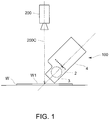
- the line light irradiating device 100 is adapted to irradiate , for example, an irradiation target surface W1 of an inspection object (work) W with line shaped light, in which a photograph of the irradiation target surface W1 is taken by an image pickup device 200 such as a line sensor, and the obtained image data is captured by an image processing device (not shown) and used in such as a product inspection system that performs an automatic inspection, for example, an inspection of presence or absence of defects such as scratches and dirt, foreign matters in liquid, or mark inspection.
- an irradiation width of the line shaped light is appropriately set according to an application and it may be wide or narrow so long as it is in accordance with the application.
- the line light irradiating device 100 shown in Fig. 1 is arranged so as to irradiate the irradiation target surface W1 with the line shaped light from a direction inclined with respect to a direction orthogonal thereto (a vertical direction in the present embodiment), and an image pickup device 200 is arranged with its image pickup axis 200C being orthogonal to the irradiation target surface W1.
- the work W is transported along a predetermined transport direction.
- the line light irradiating device 100 includes: a plurality of LEDs 2 arranged in a predetermined direction; a rod lens 3 for condensing light of the plurality of LEDs 2; and an elongate-shaped casing 4 for accommodating the plurality of LEDs 2 and the rod lens 3.
- the plurality of LEDs 2 are mounted on a rectangular plate shaped LED mounting substrate 20, for example, at equal intervals in a row along the longitudinal direction thereof.
- the rod lens 3 is provided along an arrangement direction of the plurality of LEDs 2 in a light emitting side of the plurality of LEDs 2.
- This rod lens 3 is adapted to have a circular shape in cross section and it is made of resin such as plastic (for example, acrylic).
- the casing 4 is adapted to have an accommodating space 2S extending in the longitudinal direction for accommodating the LED mounting substrate 20 and the rod lens 3, having a light emitting portion 2X formed in a tip end surface for emitting the line shaped light.
- the casing 4 includes a pair of longitudinal side wall portions 41 and 42 in parallel to each other extending in the longitudinal direction while holding the rod lens 3 therebetween and a bottom wall portion 43 extending in the longitudinal direction for connecting between the paired longitudinal side wall portions 41 and 42.
- a radiating fin 43F extending in the longitudinal direction on the bottom wall portion 43.
- This casing 4 is made of metal (for example, made of aluminum), which is formed of the paired longitudinal side wall portions 41 and 42 and the bottom wall portion 43 integrally formed by such as extrusion molding.
- closure blocks 44 and 45 for closing the openings of the both ends in the longitudinal direction of an accommodating space 2S formed between the paired longitudinal side wall portions 41 and 42.
- a power supply connector (not shown) for supplying electric power to the plurality of LEDs 2.
- a diffusion plate 6 for making an illumination distribution of the line light emitted from the rod lens 3 uniform.
- This diffusion plate 6 is provided in front of the light emitting side (i.e., above) of the rod lens 3, and a protection cover may be provided on the light emitting side surface (i.e., upper surface) of the diffusion plate 6.
- the line light irradiating device 100 of the present embodiment includes a fixing member 5 provided between the right side wall portion 42 and the rod lens 3 and pressed against a longitudinal side surface 3a of the rod lens 3 to thereby fix the rod lens 3.
- the fixing member 5 the rod lens 3 is held between the left side wall portion 41 and the right side wall portion 42.
- This fixing member 5 is adapted to have rigidity higher than that of the resin rod lens 3, and it is made of metal such as aluminum.
- the fixing member 5 includes a rectangular elongate-shaped plate material and it is adapted to have the same shape in cross section in the longitudinal direction. Further, a size in the longitudinal direction of the fixing member 5 is approximately equal to that of the rod lens 3, and the fixing member 5 is configured so as to be in contact with an overall length from one end to the other end in the longitudinal direction of the rod lens 3.
- a lens reference surface 41x being in contact with a longitudinal side surface 3a of the rod lens 3 and serving as a positioning reference of the rod lens 3.
- This lens reference surface 41x is integrally provided with the left side wall portion 41 and it is formed along the longitudinal direction in its inner surface.
- the lens reference surface 41x is adapted to be in contact with two positions apart from each other in a circumferential direction of the rod lens 3 in cross section orthogonal to the longitudinal direction, having a first surface 41x1 oriented to the light emitting side of the LEDs 2 and a second surface 41x2 formed in a light emitting side rather than the first surface 41x1 and just opposing to the right side wall portion 42.
- the first surface 41x1 is formed on a convex portion 411 protruded inward from an inner surface of the left side wall portion 41.
- a supporting surface 42x for supporting the rod lens 3 together with the lens reference surface 41x.
- This supporting surface 42x is formed of a convex portion 421 which is oriented toward the light emitting side of the LEDs 2 and protruded inwardly from the inner surface of the right side wall portion 42.
- the fixing member 5 is arranged in the clearance surrounded by the surface oriented to the light emitting side of the convex portion 421 (i.e., upper surface in Fig. 3 ), the longitudinal side surface 3a of the rod lens 3, and the inner surface of the right side wall portion 42.
- a female screw hole 42h into which a pushing screw 7 is screwed, the pushing screw 7 being for pushing the fixing member 5 accommodated in the clearance toward the side of the rod lens 3 (i.e., the side of the left side wall portion 41).
- This female screw hole 42h is provided in each of two positions in the longitudinal direction of the right side wall portion 42.
- this fixing structure it is configured that the fixing member 5 is pushed by the pushing screw 7 in a state of being arranged in the clearance so as to be pressed against the longitudinal side surface 3a of the light emitting side of the LEDs 2 rather than the center C in cross section of the rod lens 3.
- the pushing screw 7 is provided at a position shifted toward the light emitting side rather than the center C in cross section of the rod lens 3.
- the rod lens 3 is pressed against the second surface 41x2, and distortion mainly in the crosswise direction is thereby corrected. Further, the rod lens 3 is pressed against the first surface 41x1, and distortion mainly in the vertical direction is thereby corrected. Note that the rod lens 3 may be either separated from the supporting surface 42x or remains in contact with the same.
- a substrate reference surface 4z in the side of the left side wall portion 41 which is in contact with a longitudinal side surface of an LED mounting substrate 20 and serves as a positioning reference of the LED mounting substrate 20.
- This substrate reference surface 4z may be formed along the longitudinal direction in the inner surface of the left side wall portion 41 or may be formed in the side of the left side wall portion 41 on an upper surface of the bottom wall portion 43.
- the LED mounting substrate 20 is fixed to the bottom wall portion 43 in a state of being in contact with the substrate reference surface 4z.
- the LED mounting substrate 20 is positioned in the crosswise direction with respect to the left side wall portion 41.
- the line light irradiating device 100 of the present embodiment configured as described above, since the rigidity of the fixing member 5 is higher than that of the rod lens 3, by pressing the fixing member 5 against the rod lens 3, the rod lens 3 can be deformed.
- the fixing member 5 is elongate-shaped and the distortion of the rod lens 3 can be corrected along the longitudinal direction.
- the rod lens 3 can be fixed while the distortion of the rod lens 3 is being corrected.
- the casing 4 is an integrally formed product made of metal and the fixing member 5 is made of metal, the distortion of the rod lens 3 can be surely corrected.
- the rod lens 3 is held and fixed between the left side wall portion 41 and the fixing member 5, the positioning accuracy of the rod lens 3 with respect to the left side wall portion 41 can be improved. Further, the number of parts can be reduced. In this configuration, since the LED mounting substrate 20 is also positioned with respect to the left side wall portion 41, the rod lens 3 and the LED mounting substrate 20 (LEDs 2) can be easily positioned with high accuracy.
- the fixing member 5 arranged between the right side wall portion 42 and the rod lens 3 is pressed against the longitudinal side surface 3a of the rod lens 3 by the pushing screw 7, the rod lens 3 is not damaged at all. Further, by fastening and loosening the pushing screw 7, the degree of correcting the distortion of the rod lens 3 can be adjusted.
- the fixing member 5 since the fixing member 5 is pressed against the longitudinal side surface 3a of the light emitting side of the LEDs 2 rather than the center C in cross section of the rod lens 3, the rod lens 3 can be prevented from deviating to the light emitting side.
- the fixing member 5 is adapted to be fixed by the pushing screw 7, otherwise, the fixing member 5 may be adapted to be pressed against the rod lens 3 by another way of intermittently inserting a wedge member into a portion between the fixing member 5 and the right side wall portion 42.
- one rod lens 3 is adapted to be pressed by one fixing member 5
- two or more fixing members are arranged along the longitudinal direction of the one rod lens 3 on the side of the right side wall portion 42 and the one rod lens 3 may be adapted to be pressed by the two or more fixing members.
- the fixing members are provided on both sides of the pair of longitudinal side wall portions 41 and 42 to thereby be pressed against the rod lens 3.
- the shape of the fixing member 5 is not limited to the above embodiment, and any shape may be also possible so long as the fixing member is arranged between the rod lens 3 and the longitudinal side wall portions 41 and 42 so as to be able to be pressed against the longitudinal side surface 3a of the rod lens 3.
- the lens reference surface 41x provided in the left side wall portion 41 in addition to that integrally formed with the left side wall portion 41, it may be formed by fixing a lens reference surface forming member for forming the lens reference surface 41x to the inner surface of the left side wall portion 41.
- the lens reference surface 41x is not limited to the above embodiment, and it may be also possible so long as it has a shape in cross section being in contact with two or more positions in the circumferential direction in the longitudinal side surface of the rod lens 3.
- the lens reference surface 41x may be possible so long as it has a circular shaped or V grove shaped portion in cross section.
- the rod lens 3 as a rod-shaped lens
- a condensing lens such as a cylindrical lens of the other types may be used.
- the line light irradiating device 100 may be adapted to an application of performing resin cure or exposure by applying ultraviolet light, besides for inspection.
- the rod-shaped lens since the rod-shaped lens is pressed by the fixing member having rigidity higher than that of the rod-shaped lens, the rod-shaped lens can be fixed while correcting the distortion of the rod-shaped lens.
Landscapes
- Engineering & Computer Science (AREA)
- General Engineering & Computer Science (AREA)
- Physics & Mathematics (AREA)
- Health & Medical Sciences (AREA)
- Life Sciences & Earth Sciences (AREA)
- Chemical & Material Sciences (AREA)
- Analytical Chemistry (AREA)
- Biochemistry (AREA)
- General Health & Medical Sciences (AREA)
- General Physics & Mathematics (AREA)
- Immunology (AREA)
- Pathology (AREA)
- Non-Portable Lighting Devices Or Systems Thereof (AREA)
- Investigating Materials By The Use Of Optical Means Adapted For Particular Applications (AREA)
Description
- The present invention relates to a line light irradiating device which is adapted to irradiate an object (work) such as a product with line shaped light, for example, in a factory and suitably used for appearance inspection thereof.
- As a line light irradiating device of this kind, there is a configuration of a plurality of LEDs provided along a longitudinal direction and a rod lens for condensing light emitted from the plurality of LEDs and emitting line shaped light, which are accommodated in a casing extending in the longitudinal direction, as disclosed in
Patent Literatures - Further, a rod lens made of resin such as plastic material is generally used, and this resin rod lens is manufactured by extrusion molding using, for example, metal mold.
- However, in a resin rod lens, there sometimes occurs distortion in a longitudinal direction due to a nature of processing thereof. Due to this distortion in the longitudinal direction, there arises a problem that unevenness in illuminance or unevenness in illumination width of the line light irradiated from the line light irradiating device and that the line light may be sometimes curved.
- Here, in
Patent Literature 1, in order to dissolve deviation in fixed position due to a waved shape caused on a rod lens surface, there is adopted a configuration of inserting a flexible buffer member between the rod lens and the casing (in specific, a fixed projection). In this configuration, however, since the buffer member has flexibility, the distortion in the longitudinal direction of the rod lens cannot be corrected, and there may still occur unevenness in illuminance of the line light due to the distortion in the longitudinal direction. - Further, in
Patent Literature 2, although a rod lens is fixed to a casing via a holding member, it is insufficient to dissolve the distortion in the longitudinal direction of the rod lens. -
- Patent Literature 1:
JP 2010-112939A - Patent Literature 2:
JP 2015-125003A - Further technological background can be found in
JP 2016 014599 A - Therefore, the present invention has been made in order to solve the above problems, and its essential object is to fix a rod-shaped lens while correcting distortion of the rod-shaped lens.
- That is, a line light irradiating device according the present invention includes: a plurality of LEDs arranged in a predetermined direction; a resin rod-shaped lens provided along the arrangement direction of the plurality of LEDs and condensing light of the plurality of LEDs; a casing for accommodating the plurality of LEDs and the rod-shaped lens, the casing having a pair of longitudinal side wall portions provided in a manner of holding the rod-shaped lens therebetween; and a fixing member provided between one of the longitudinal side wall portions and the rod-shaped lens and pressed against a longitudinal side surface of the rod-shaped lens by being pressed in the direction of the other of the longitudinal side wall portions to thereby fix the rod-shaped lens, wherein the fixing member is elongate-shaped, having rigidity higher than that of the rod-shaped lens.
- With such a line light irradiating device, since the rigidity of the fixing member is higher than that of the rod-shaped lens, the rod-shaped lens can be deformed by pressing the fixing member against the rod-shaped lens. Specifically, since the fixing member is elongate-shaped, it is advantageous to correct distortion of the rod-shaped lens in a longitudinal direction. Thus, the rod-shaped lens can be fixed while correcting the distortion of the rod-shaped lens.
- In the present invention, the fixing members may be provided on both sides of the paired longitudinal side wall portions to thereby hold the rod-shaped lens therebetween by the fixing members on the both sides, however, in this configuration, not only the number of parts increases but also, since the fixing members are arranged on the both sides of the rod-shaped lens separately from the casing, positioning for fixing the rod-shaped lens with respect to the casing becomes difficult and this may be consequently difficult to accurately position the rod-shaped lens with respect to the plurality of LEDs fixed to the casing.
- In order to appropriately solve this problem, it is preferable that, the other of the longitudinal side wall portions has a lens reference surface being in contact with the longitudinal side surface of the rod-shaped lens and serving as a positioning reference of the rod-shaped lens and the fixing member is provided between the one of the longitudinal side wall portions and the rod-shaped lens and is adapted to be pressed against the longitudinal side surface of the rod-shaped lens to thereby press the rod-shaped lens against the lens reference surface.
- With this configuration, since the rod-shaped lens is held and fixed between the other of the longitudinal side wall portions and the fixing member, the positioning accuracy of the rod-shaped lens with respect to the other of the longitudinal side wall portions can be improved. Further, the number of parts can be reduced.
- Here, it may be considered to have a configuration that the fixing member is pressed against the longitudinal side surface of the rod-shaped lens by pushing the fixing member from the outside into a space between the one longitudinal side wall portion and the rod-shaped lens. However, in this configuration, it is afraid that the rod-shaped lens may be damaged due to frictions at the time of pushing therein. Further, it is difficult to adjust a correction degree of distortion of the rod-shaped lens after pushing the fixing member therein.
- In order to solve this problem, it is preferable that, the fixing member is adapted to be pressed against the longitudinal side surface of the rod-shaped lens by a pushing screw engaged in the one of the longitudinal side wall portions.
- With this configuration, the fixing member can be pushed toward the rod-shaped lens side by the pushing screw after the fixing member is arranged between the one of the longitudinal side wall portions and the rod-shaped lens and it is possible to suppress the rod-shaped lens from being damaged. Further, it is possible to adjust the correction degree of the distortion of the rod-shaped lens by fastening and loosening the pushing screw.
- In order to position the rod-shaped lens to a position apart from the LEDs by a predetermined distance by the lens reference surface, it is preferable that the lens reference surface has a first surface oriented to a light emitting side of the LEDs. With this configuration, the rod-shaped lens can be positioned with respect to the LEDs by making the rod-shaped lens abut to the first surface.
- Further, merely by pressing the rod-shaped lens against the side of the other of the longitudinal side wall portions, i.e., merely by pressing the rod-shaped lens from a direction (lateral direction) orthogonal to the light emitting direction, it is afraid that the rod-shaped lens may be deviated to the light emitting side, however, in the case where the fixing member is configured to be pressed against a longitudinal side surface in the light emitting side of the LEDs rather than a center in cross section of the rod-shaped lens, this problem can be prevented from occurrence.
- Further, in the case where the fixing member is adapted to have a flat plane shape and to be arranged in a clearance formed between the one of the longitudinal side wall portions and the rod-shaped lens, the configuration can be simplified.
- It is preferable that, the plurality of LEDs are mounted on an elongate-shaped substrate, and the casing has a substrate reference surface in the side of the other of the longitudinal side wall portions, the substrate reference surface being in contact with a longitudinal side surface of the substrate and serving as a positioning reference of the substrate, and the substrate is fixed while being in contact with the substrate reference surface.
- With this configuration, the rod-shaped lens and the LEDs can be positioned with reference to the side of the one of the longitudinal side wall portions, and the positioning of the rod-shaped lens and the LEDs can be easily performed.
- In order to increase the rigidity of the casing, it is preferable that the casing is adapted to have a configuration that the paired longitudinal side wall portions are integrally formed with a bottom wall portion connecting between the paired longitudinal side wall portions.
- With this configuration, the casing becomes hard to be deformed by a force received by the casing from the fixing member pressing the rod-shaped lens or by a force applied to the casing from the rod-shaped lens pressed by the fixing member, and the distortion of the rod-shaped lens can be surely corrected. Moreover, in the case where the casing and the fixing member are made of metal, the rigidity of a constant level or higher can be easily secured to be advantageous.
- According to the present invention configured as described above, since the rod-shaped lens is pressed by the fixing member having rigidity higher than that of the rod-shaped lens, the rod-shaped lens can be fixed while correcting the distortion of the rod-shaped lens. Therefore, the line light irradiated from the line light irradiating device can be made straight with evenness in irradiation width without unevenness in illumination.
-
-
Fig. 1 is a schematic view showing an inspection system using a line light irradiating device of the present embodiment; -
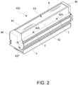
Fig. 2 is a perspective view showing the line light irradiating device of the same embodiment; -
Fig. 3 is a cross sectional view showing the line light irradiating device of the same embodiment; and -
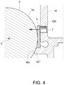
Fig. 4 is a schematic view showing a state of pushing a fixing member by a pushing screw of the same embodiment. -
- 100 ...
- Line light irradiating device
- 2 ...
- LED
- 20 ...
- Substrate (LED mounting substrate)
- 3 ...
- Rod-shaped lens
- 3a ...
- Longitudinal side surface
- 4 ...
- Casing
- 41 ...
- Left side wall portion (other longitudinal side wall portion)
- 41x ...
- Lens reference surface
- 41x1 ...
- First surface
- 41x2 ...
- Second surface
- 42 ...
- Right side wall portion (one longitudinal side wall portion)
- 42x ...
- Supporting surface
- 43 ...
- Bottom wall portion
- 5 ...
- Fixing member
- 7 ...
- Pushing screw
- A first embodiment of a line light irradiating device according to the present invention is described below with reference to the drawings.
- As shown in
Fig. 1 , the linelight irradiating device 100 according to the present embodiment is adapted to irradiate , for example, an irradiation target surface W1 of an inspection object (work) W with line shaped light, in which a photograph of the irradiation target surface W1 is taken by animage pickup device 200 such as a line sensor, and the obtained image data is captured by an image processing device (not shown) and used in such as a product inspection system that performs an automatic inspection, for example, an inspection of presence or absence of defects such as scratches and dirt, foreign matters in liquid, or mark inspection. Note that, an irradiation width of the line shaped light is appropriately set according to an application and it may be wide or narrow so long as it is in accordance with the application. - The line
light irradiating device 100 shown inFig. 1 is arranged so as to irradiate the irradiation target surface W1 with the line shaped light from a direction inclined with respect to a direction orthogonal thereto (a vertical direction in the present embodiment), and animage pickup device 200 is arranged with itsimage pickup axis 200C being orthogonal to the irradiation target surface W1. Here, the work W is transported along a predetermined transport direction. - In specific, as shown in
Figs. 2 and3 , the linelight irradiating device 100 includes: a plurality ofLEDs 2 arranged in a predetermined direction; arod lens 3 for condensing light of the plurality ofLEDs 2; and an elongate-shapedcasing 4 for accommodating the plurality ofLEDs 2 and therod lens 3. - The plurality of
LEDs 2 are mounted on a rectangular plate shapedLED mounting substrate 20, for example, at equal intervals in a row along the longitudinal direction thereof. - The
rod lens 3 is provided along an arrangement direction of the plurality ofLEDs 2 in a light emitting side of the plurality ofLEDs 2. Thisrod lens 3 is adapted to have a circular shape in cross section and it is made of resin such as plastic (for example, acrylic). - The
casing 4 is adapted to have anaccommodating space 2S extending in the longitudinal direction for accommodating theLED mounting substrate 20 and therod lens 3, having alight emitting portion 2X formed in a tip end surface for emitting the line shaped light. - In specific, the
casing 4 includes a pair of longitudinalside wall portions rod lens 3 therebetween and abottom wall portion 43 extending in the longitudinal direction for connecting between the paired longitudinalside wall portions fin 43F extending in the longitudinal direction on thebottom wall portion 43. Note that, in the following description, one longitudinal side wall portion of the paired longitudinalside wall portions side wall portion 42 and the other of the longitudinal side wall portions is referred to as a leftside wall portion 41. - This
casing 4 is made of metal (for example, made of aluminum), which is formed of the paired longitudinalside wall portions bottom wall portion 43 integrally formed by such as extrusion molding. - Further, on both end portions in the longitudinal direction of the
casing 4, there are fixed closure blocks 44 and 45 for closing the openings of the both ends in the longitudinal direction of anaccommodating space 2S formed between the paired longitudinalside wall portions LEDs 2. - Moreover, under the
light emitting portion 2X of thecasing 4, there is provided adiffusion plate 6 for making an illumination distribution of the line light emitted from therod lens 3 uniform. Thisdiffusion plate 6 is provided in front of the light emitting side (i.e., above) of therod lens 3, and a protection cover may be provided on the light emitting side surface (i.e., upper surface) of thediffusion plate 6. - Thus, as shown in
Fig. 3 , the linelight irradiating device 100 of the present embodiment includes a fixingmember 5 provided between the rightside wall portion 42 and therod lens 3 and pressed against alongitudinal side surface 3a of therod lens 3 to thereby fix therod lens 3. By this fixingmember 5, therod lens 3 is held between the leftside wall portion 41 and the rightside wall portion 42. - This fixing
member 5 is adapted to have rigidity higher than that of theresin rod lens 3, and it is made of metal such as aluminum. In specific, the fixingmember 5 includes a rectangular elongate-shaped plate material and it is adapted to have the same shape in cross section in the longitudinal direction. Further, a size in the longitudinal direction of the fixingmember 5 is approximately equal to that of therod lens 3, and the fixingmember 5 is configured so as to be in contact with an overall length from one end to the other end in the longitudinal direction of therod lens 3. - The following describes a fixing structure by the fixing
member 5 with reference toFig. 3 . - On the left
side wall portion 41, there is provided alens reference surface 41x being in contact with alongitudinal side surface 3a of therod lens 3 and serving as a positioning reference of therod lens 3. Thislens reference surface 41x is integrally provided with the leftside wall portion 41 and it is formed along the longitudinal direction in its inner surface. - The
lens reference surface 41x is adapted to be in contact with two positions apart from each other in a circumferential direction of therod lens 3 in cross section orthogonal to the longitudinal direction, having a first surface 41x1 oriented to the light emitting side of theLEDs 2 and a second surface 41x2 formed in a light emitting side rather than the first surface 41x1 and just opposing to the rightside wall portion 42. The first surface 41x1 is formed on aconvex portion 411 protruded inward from an inner surface of the leftside wall portion 41. - Further, on the right
side wall portion 42, there is formed a supportingsurface 42x for supporting therod lens 3 together with thelens reference surface 41x. This supportingsurface 42x is formed of aconvex portion 421 which is oriented toward the light emitting side of theLEDs 2 and protruded inwardly from the inner surface of the rightside wall portion 42. - There is formed a clearance for accommodating the fixing
member 5 between thelongitudinal side surface 3a of therod lens 3 and the inner surface of the rightside wall portion 42 in a state that therod lens 3 is supported by thelens reference surface 41x and the supportingsurface 42x. That is, the fixingmember 5 is arranged in the clearance surrounded by the surface oriented to the light emitting side of the convex portion 421 (i.e., upper surface inFig. 3 ), thelongitudinal side surface 3a of therod lens 3, and the inner surface of the rightside wall portion 42. - Further, in the right
side wall portion 42, there is formed afemale screw hole 42h into which a pushingscrew 7 is screwed, the pushingscrew 7 being for pushing the fixingmember 5 accommodated in the clearance toward the side of the rod lens 3 (i.e., the side of the left side wall portion 41). Thisfemale screw hole 42h is provided in each of two positions in the longitudinal direction of the rightside wall portion 42. - In this fixing structure, it is configured that the fixing
member 5 is pushed by the pushingscrew 7 in a state of being arranged in the clearance so as to be pressed against thelongitudinal side surface 3a of the light emitting side of theLEDs 2 rather than the center C in cross section of therod lens 3. In specific, the pushingscrew 7 is provided at a position shifted toward the light emitting side rather than the center C in cross section of therod lens 3. Thus, by fastening this pushingscrew 7 and pushing the flat plate shaped fixingmember 5, the fixingmember 5 is pressed against thelongitudinal side surface 3a of therod lens 3 and it is tilted or deformed so as to overlay thelongitudinal side surface 3a (seeFig. 4 ). - This results in that the
rod lens 3 is pushed against the side of the leftside wall portion 41 and the side of theLEDs 2 of the rod lens 3 (i.e., toward the opposite side of the light emitting side) and it is pressed against both of the first surface 41x1 and the second surface 41x2 of thelens reference surface 41x, and therod lens 3 is positioned and fixed in the crosswise direction and vertical direction with respect to the leftside wall portion 41. - At this time, the
rod lens 3 is pressed against the second surface 41x2, and distortion mainly in the crosswise direction is thereby corrected. Further, therod lens 3 is pressed against the first surface 41x1, and distortion mainly in the vertical direction is thereby corrected. Note that therod lens 3 may be either separated from the supportingsurface 42x or remains in contact with the same. - Further, inside of the
casing 4, there is formed asubstrate reference surface 4z in the side of the leftside wall portion 41 which is in contact with a longitudinal side surface of anLED mounting substrate 20 and serves as a positioning reference of theLED mounting substrate 20. Thissubstrate reference surface 4z may be formed along the longitudinal direction in the inner surface of the leftside wall portion 41 or may be formed in the side of the leftside wall portion 41 on an upper surface of thebottom wall portion 43. And theLED mounting substrate 20 is fixed to thebottom wall portion 43 in a state of being in contact with thesubstrate reference surface 4z. Thus, theLED mounting substrate 20 is positioned in the crosswise direction with respect to the leftside wall portion 41. - According to the line
light irradiating device 100 of the present embodiment configured as described above, since the rigidity of the fixingmember 5 is higher than that of therod lens 3, by pressing the fixingmember 5 against therod lens 3, therod lens 3 can be deformed. In specific, the fixingmember 5 is elongate-shaped and the distortion of therod lens 3 can be corrected along the longitudinal direction. Thus, therod lens 3 can be fixed while the distortion of therod lens 3 is being corrected. In this configuration, since thecasing 4 is an integrally formed product made of metal and the fixingmember 5 is made of metal, the distortion of therod lens 3 can be surely corrected. - Further, since the
rod lens 3 is held and fixed between the leftside wall portion 41 and the fixingmember 5, the positioning accuracy of therod lens 3 with respect to the leftside wall portion 41 can be improved. Further, the number of parts can be reduced. In this configuration, since theLED mounting substrate 20 is also positioned with respect to the leftside wall portion 41, therod lens 3 and the LED mounting substrate 20 (LEDs 2) can be easily positioned with high accuracy. - Moreover, since the fixing
member 5 arranged between the rightside wall portion 42 and therod lens 3 is pressed against thelongitudinal side surface 3a of therod lens 3 by the pushingscrew 7, therod lens 3 is not damaged at all. Further, by fastening and loosening the pushingscrew 7, the degree of correcting the distortion of therod lens 3 can be adjusted. - In addition, since the fixing
member 5 is pressed against thelongitudinal side surface 3a of the light emitting side of theLEDs 2 rather than the center C in cross section of therod lens 3, therod lens 3 can be prevented from deviating to the light emitting side. - Note that, the present invention should not be limited to the present embodiment.
- For example, in the above embodiment, although the fixing
member 5 is adapted to be fixed by the pushingscrew 7, otherwise, the fixingmember 5 may be adapted to be pressed against therod lens 3 by another way of intermittently inserting a wedge member into a portion between the fixingmember 5 and the rightside wall portion 42. - Further, in the above embodiment, although one
rod lens 3 is adapted to be pressed by one fixingmember 5, it may be also possible that two or more fixing members are arranged along the longitudinal direction of the onerod lens 3 on the side of the rightside wall portion 42 and the onerod lens 3 may be adapted to be pressed by the two or more fixing members. In addition, it may be also possible that the fixing members are provided on both sides of the pair of longitudinalside wall portions rod lens 3. - Moreover, the shape of the fixing
member 5 is not limited to the above embodiment, and any shape may be also possible so long as the fixing member is arranged between therod lens 3 and the longitudinalside wall portions longitudinal side surface 3a of therod lens 3. - Furthermore, regarding the
lens reference surface 41x provided in the leftside wall portion 41, in addition to that integrally formed with the leftside wall portion 41, it may be formed by fixing a lens reference surface forming member for forming thelens reference surface 41x to the inner surface of the leftside wall portion 41. - In addition, the
lens reference surface 41x is not limited to the above embodiment, and it may be also possible so long as it has a shape in cross section being in contact with two or more positions in the circumferential direction in the longitudinal side surface of therod lens 3. For example, in the case of therod lens 3 having a circular shape in cross section, thelens reference surface 41x may be possible so long as it has a circular shaped or V grove shaped portion in cross section. - Furthermore, in the above embodiment, although an example using the
rod lens 3 as a rod-shaped lens is shown, a condensing lens such as a cylindrical lens of the other types may be used. Also, the linelight irradiating device 100 may be adapted to an application of performing resin cure or exposure by applying ultraviolet light, besides for inspection. - According to the present invention, since the rod-shaped lens is pressed by the fixing member having rigidity higher than that of the rod-shaped lens, the rod-shaped lens can be fixed while correcting the distortion of the rod-shaped lens.
Claims (7)
- A line light irradiating device (100) comprising:a plurality of LEDs (2) arranged in a predetermined direction;a resin rod-shaped lens (3) provided along the arrangement direction of the plurality of LEDs (2) and condensing light of the plurality of LEDs (2);a casing (4) for accommodating the plurality of LEDs (2) and the rod-shaped lens (3), the casing (4) having a pair of longitudinal side wall portions (41, 42) provided in a manner of holding the rod-shaped lens (3) therebetween; anda fixing member (5) provided between one of the longitudinal side wall portions (41, 42) and the rod-shaped lens (3), characterized in that the fixing member (5) is pressed against a longitudinal side surface of the rod-shaped lens (3) by being pressed in the direction of the other of the longitudinal side wall portions (41, 42) by a pushing screw (7) or a wedge member to thereby fix the rod-shaped lens (3),wherein the fixing member (5) is elongate-shaped, having rigidity higher than that of the rod-shaped lens (3).
- The line light irradiating device (100) according to claim 1, wherein the other of the longitudinal side wall portions (41, 42) has a lens reference surface (41x) being in contact with the longitudinal side surface of the rod-shaped lens (3) and serving as a positioning reference of the rod-shaped lens (3), and
wherein the fixing member (5) is provided between the one of the longitudinal side wall portions (41, 42) and the rod-shaped lens (3) and is adapted to be pressed against the longitudinal side surface of the rod-shaped lens (3) to thereby press the rod-shaped lens (3) against the lens reference surface (41x). - The line light irradiating device (100) according to claim 2, wherein the rod-shaped lens (3) has a circular shape in cross section orthogonal to a longitudinal direction,
wherein the lens reference surface (41x) has a first surface (41x1) oriented to a light emitting side of the LEDs (2), and
wherein the fixing member (5) is adapted to be pressed against a longitudinal side surface in the light emitting side of the LEDs (2) rather than a center in cross section of the rod-shaped lens (3). - The line light irradiating device (100) according to claim 2, wherein the fixing member (5) is adapted to have a flat plane shape and to be arranged in a clearance formed between the one of the longitudinal side wall portions (41, 42) and the rod-shaped lens (3).
- The line light irradiating device (100) according to claim 1 or 2, wherein the pushing screw (7) is engaged in the one of the longitudinal side wall portions (41, 42).
- The line light irradiating device (100) according to claim 2, wherein the plurality of LEDs (2) are mounted on an elongate-shaped substrate (20),
wherein the casing (4) has a substrate reference surface (4z) in the side of the other of the longitudinal side wall portions (41, 42), the substrate reference surface (4z) being in contact with a longitudinal side surface of the substrate (20) and serving as a positioning reference of the substrate (20), and
wherein the substrate (20) is fixed while being in contact with the substrate reference surface (4z). - The line light irradiating device (100) according to claim 1, wherein the casing (4) is adapted to have a configuration that the paired longitudinal side wall portions (41, 42) are integrally formed with a bottom wall portion (43) connecting between the paired longitudinal side wall portions (41, 42).
Applications Claiming Priority (2)
| Application Number | Priority Date | Filing Date | Title |
|---|---|---|---|
| JP2016031932A JP6748443B2 (en) | 2016-02-23 | 2016-02-23 | Line light irradiation device |
| PCT/JP2017/006321 WO2017146030A1 (en) | 2016-02-23 | 2017-02-21 | Line light irradiating device |
Publications (3)
| Publication Number | Publication Date |
|---|---|
| EP3421978A1 EP3421978A1 (en) | 2019-01-02 |
| EP3421978A4 EP3421978A4 (en) | 2019-10-16 |
| EP3421978B1 true EP3421978B1 (en) | 2020-11-11 |
Family
ID=59685208
Family Applications (1)
| Application Number | Title | Priority Date | Filing Date |
|---|---|---|---|
| EP17756468.9A Active EP3421978B1 (en) | 2016-02-23 | 2017-02-21 | Line light irradiating device |
Country Status (3)
| Country | Link |
|---|---|
| EP (1) | EP3421978B1 (en) |
| JP (1) | JP6748443B2 (en) |
| WO (1) | WO2017146030A1 (en) |
Families Citing this family (4)
| Publication number | Priority date | Publication date | Assignee | Title |
|---|---|---|---|---|
| JP7522429B2 (en) * | 2020-03-27 | 2024-07-25 | 株式会社アイテックシステム | Lighting equipment |
| JP7178026B2 (en) * | 2020-04-30 | 2022-11-25 | レボックス株式会社 | lighting equipment |
| JP2023173165A (en) * | 2022-05-25 | 2023-12-07 | 株式会社リコー | Lighting device and image reading device |
| WO2025115911A1 (en) | 2023-12-01 | 2025-06-05 | シーシーエス株式会社 | Light irradiation device and light irradiation method |
Family Cites Families (9)
| Publication number | Priority date | Publication date | Assignee | Title |
|---|---|---|---|---|
| US7261435B2 (en) * | 2004-06-18 | 2007-08-28 | Acuity Brands, Inc. | Light fixture and lens assembly for same |
| JP4457100B2 (en) * | 2006-01-30 | 2010-04-28 | 株式会社アイテックシステム | Lighting device |
| JP2009288206A (en) * | 2008-06-02 | 2009-12-10 | Tech Vision:Kk | Line type light source device |
| JP2010114054A (en) * | 2008-11-05 | 2010-05-20 | Tozai Denko Co Ltd | Light source device |
| KR101223958B1 (en) * | 2011-09-30 | 2013-01-21 | 원철희 | Led module combined with rod lens |
| JP2014122799A (en) * | 2012-12-20 | 2014-07-03 | Ccs Inc | Line light radiation device |
| JP6302242B2 (en) * | 2013-12-25 | 2018-03-28 | 株式会社アイテックシステム | Lighting device |
| JP6571317B2 (en) * | 2014-07-02 | 2019-09-04 | 株式会社アイテックシステム | Line-shaped illumination device, manufacturing method and inspection method thereof |
| JP6580511B2 (en) * | 2015-04-07 | 2019-09-25 | レボックス株式会社 | Lighting device |
-
2016
- 2016-02-23 JP JP2016031932A patent/JP6748443B2/en active Active
-
2017
- 2017-02-21 EP EP17756468.9A patent/EP3421978B1/en active Active
- 2017-02-21 WO PCT/JP2017/006321 patent/WO2017146030A1/en not_active Ceased
Non-Patent Citations (1)
| Title |
|---|
| None * |
Also Published As
| Publication number | Publication date |
|---|---|
| WO2017146030A1 (en) | 2017-08-31 |
| JP2017150875A (en) | 2017-08-31 |
| JP6748443B2 (en) | 2020-09-02 |
| EP3421978A4 (en) | 2019-10-16 |
| EP3421978A1 (en) | 2019-01-02 |
Similar Documents
| Publication | Publication Date | Title |
|---|---|---|
| EP3421978A1 (en) | Line light irradiating device | |
| KR101483896B1 (en) | Line light irradiation device and manufacturing method thereof | |
| US10185112B2 (en) | Optical module with design feature for mounting | |
| US8436375B2 (en) | Light illuminating device | |
| CN108204570B (en) | Primary optical assembly for installation in a motor vehicle lighting device and motor vehicle lighting device having such a primary optical assembly | |
| JP6289746B2 (en) | Vehicle headlamp | |
| US10107470B2 (en) | Device for positioning a light support for an electroluminescent diode on a support element and light module for an illumination and/or signaling device comprising such a device | |
| JP5354492B2 (en) | LED lighting device | |
| CN111725114A (en) | Position correction device for heating lamps | |
| JP6529816B2 (en) | Lighting fixture, mounting bracket and mounting bracket set | |
| KR102207297B1 (en) | Light illuminating apparatus | |
| TW201400909A (en) | Projection device and lens module | |
| JP2018034935A5 (en) | Photo interrupter unit, sheet conveying apparatus, and image forming apparatus | |
| US10641461B2 (en) | Light illuminating apparatus | |
| KR20120127179A (en) | Illuminating device | |
| JPWO2019073768A1 (en) | Connecting unit and connecting device | |
| JP2010122047A (en) | Lighting system | |
| TWI536610B (en) | Method for manufacturing light emitting diode module | |
| US20190211992A1 (en) | Vehicle lamp | |
| KR101563107B1 (en) | Led lamp for implementing seamless led illumination apparatus | |
| KR200467106Y1 (en) | Visual inspection apparatus for connector | |
| CN109154738B (en) | Flexible holding device for a light source | |
| JP5993780B2 (en) | Backup roll fixed structure | |
| TWI532950B (en) | Lamp and manufacturing method thereof | |
| JP2024150260A5 (en) |
Legal Events
| Date | Code | Title | Description |
|---|---|---|---|
| STAA | Information on the status of an ep patent application or granted ep patent |
Free format text: STATUS: THE INTERNATIONAL PUBLICATION HAS BEEN MADE |
|
| PUAI | Public reference made under article 153(3) epc to a published international application that has entered the european phase |
Free format text: ORIGINAL CODE: 0009012 |
|
| STAA | Information on the status of an ep patent application or granted ep patent |
Free format text: STATUS: REQUEST FOR EXAMINATION WAS MADE |
|
| 17P | Request for examination filed |
Effective date: 20180821 |
|
| AK | Designated contracting states |
Kind code of ref document: A1 Designated state(s): AL AT BE BG CH CY CZ DE DK EE ES FI FR GB GR HR HU IE IS IT LI LT LU LV MC MK MT NL NO PL PT RO RS SE SI SK SM TR |
|
| AX | Request for extension of the european patent |
Extension state: BA ME |
|
| DAV | Request for validation of the european patent (deleted) | ||
| DAX | Request for extension of the european patent (deleted) | ||
| A4 | Supplementary search report drawn up and despatched |
Effective date: 20190917 |
|
| RIC1 | Information provided on ipc code assigned before grant |
Ipc: F21V 5/04 20060101ALI20190911BHEP Ipc: F21V 17/12 20060101ALI20190911BHEP Ipc: F21V 17/10 20060101ALI20190911BHEP Ipc: F21Y 103/10 20160101ALI20190911BHEP Ipc: F21V 17/00 20060101ALI20190911BHEP Ipc: F21Y 115/10 20160101ALI20190911BHEP Ipc: G01N 21/84 20060101AFI20190911BHEP Ipc: F21S 2/00 20160101ALI20190911BHEP |
|
| GRAP | Despatch of communication of intention to grant a patent |
Free format text: ORIGINAL CODE: EPIDOSNIGR1 |
|
| STAA | Information on the status of an ep patent application or granted ep patent |
Free format text: STATUS: GRANT OF PATENT IS INTENDED |
|
| INTG | Intention to grant announced |
Effective date: 20200605 |
|
| GRAS | Grant fee paid |
Free format text: ORIGINAL CODE: EPIDOSNIGR3 |
|
| GRAA | (expected) grant |
Free format text: ORIGINAL CODE: 0009210 |
|
| STAA | Information on the status of an ep patent application or granted ep patent |
Free format text: STATUS: THE PATENT HAS BEEN GRANTED |
|
| AK | Designated contracting states |
Kind code of ref document: B1 Designated state(s): AL AT BE BG CH CY CZ DE DK EE ES FI FR GB GR HR HU IE IS IT LI LT LU LV MC MK MT NL NO PL PT RO RS SE SI SK SM TR |
|
| REG | Reference to a national code |
Ref country code: GB Ref legal event code: FG4D |
|
| REG | Reference to a national code |
Ref country code: CH Ref legal event code: EP |
|
| REG | Reference to a national code |
Ref country code: AT Ref legal event code: REF Ref document number: 1333967 Country of ref document: AT Kind code of ref document: T Effective date: 20201115 |
|
| REG | Reference to a national code |
Ref country code: DE Ref legal event code: R096 Ref document number: 602017027401 Country of ref document: DE |
|
| REG | Reference to a national code |
Ref country code: IE Ref legal event code: FG4D |
|
| REG | Reference to a national code |
Ref country code: NL Ref legal event code: MP Effective date: 20201111 |
|
| REG | Reference to a national code |
Ref country code: AT Ref legal event code: MK05 Ref document number: 1333967 Country of ref document: AT Kind code of ref document: T Effective date: 20201111 |
|
| PG25 | Lapsed in a contracting state [announced via postgrant information from national office to epo] |
Ref country code: PT Free format text: LAPSE BECAUSE OF FAILURE TO SUBMIT A TRANSLATION OF THE DESCRIPTION OR TO PAY THE FEE WITHIN THE PRESCRIBED TIME-LIMIT Effective date: 20210311 Ref country code: RS Free format text: LAPSE BECAUSE OF FAILURE TO SUBMIT A TRANSLATION OF THE DESCRIPTION OR TO PAY THE FEE WITHIN THE PRESCRIBED TIME-LIMIT Effective date: 20201111 Ref country code: NO Free format text: LAPSE BECAUSE OF FAILURE TO SUBMIT A TRANSLATION OF THE DESCRIPTION OR TO PAY THE FEE WITHIN THE PRESCRIBED TIME-LIMIT Effective date: 20210211 Ref country code: FI Free format text: LAPSE BECAUSE OF FAILURE TO SUBMIT A TRANSLATION OF THE DESCRIPTION OR TO PAY THE FEE WITHIN THE PRESCRIBED TIME-LIMIT Effective date: 20201111 Ref country code: GR Free format text: LAPSE BECAUSE OF FAILURE TO SUBMIT A TRANSLATION OF THE DESCRIPTION OR TO PAY THE FEE WITHIN THE PRESCRIBED TIME-LIMIT Effective date: 20210212 |
|
| PG25 | Lapsed in a contracting state [announced via postgrant information from national office to epo] |
Ref country code: AT Free format text: LAPSE BECAUSE OF FAILURE TO SUBMIT A TRANSLATION OF THE DESCRIPTION OR TO PAY THE FEE WITHIN THE PRESCRIBED TIME-LIMIT Effective date: 20201111 Ref country code: BG Free format text: LAPSE BECAUSE OF FAILURE TO SUBMIT A TRANSLATION OF THE DESCRIPTION OR TO PAY THE FEE WITHIN THE PRESCRIBED TIME-LIMIT Effective date: 20210211 Ref country code: IS Free format text: LAPSE BECAUSE OF FAILURE TO SUBMIT A TRANSLATION OF THE DESCRIPTION OR TO PAY THE FEE WITHIN THE PRESCRIBED TIME-LIMIT Effective date: 20210311 Ref country code: LV Free format text: LAPSE BECAUSE OF FAILURE TO SUBMIT A TRANSLATION OF THE DESCRIPTION OR TO PAY THE FEE WITHIN THE PRESCRIBED TIME-LIMIT Effective date: 20201111 Ref country code: PL Free format text: LAPSE BECAUSE OF FAILURE TO SUBMIT A TRANSLATION OF THE DESCRIPTION OR TO PAY THE FEE WITHIN THE PRESCRIBED TIME-LIMIT Effective date: 20201111 Ref country code: SE Free format text: LAPSE BECAUSE OF FAILURE TO SUBMIT A TRANSLATION OF THE DESCRIPTION OR TO PAY THE FEE WITHIN THE PRESCRIBED TIME-LIMIT Effective date: 20201111 |
|
| REG | Reference to a national code |
Ref country code: LT Ref legal event code: MG9D |
|
| PG25 | Lapsed in a contracting state [announced via postgrant information from national office to epo] |
Ref country code: HR Free format text: LAPSE BECAUSE OF FAILURE TO SUBMIT A TRANSLATION OF THE DESCRIPTION OR TO PAY THE FEE WITHIN THE PRESCRIBED TIME-LIMIT Effective date: 20201111 |
|
| PG25 | Lapsed in a contracting state [announced via postgrant information from national office to epo] |
Ref country code: SM Free format text: LAPSE BECAUSE OF FAILURE TO SUBMIT A TRANSLATION OF THE DESCRIPTION OR TO PAY THE FEE WITHIN THE PRESCRIBED TIME-LIMIT Effective date: 20201111 Ref country code: LT Free format text: LAPSE BECAUSE OF FAILURE TO SUBMIT A TRANSLATION OF THE DESCRIPTION OR TO PAY THE FEE WITHIN THE PRESCRIBED TIME-LIMIT Effective date: 20201111 Ref country code: EE Free format text: LAPSE BECAUSE OF FAILURE TO SUBMIT A TRANSLATION OF THE DESCRIPTION OR TO PAY THE FEE WITHIN THE PRESCRIBED TIME-LIMIT Effective date: 20201111 Ref country code: CZ Free format text: LAPSE BECAUSE OF FAILURE TO SUBMIT A TRANSLATION OF THE DESCRIPTION OR TO PAY THE FEE WITHIN THE PRESCRIBED TIME-LIMIT Effective date: 20201111 Ref country code: RO Free format text: LAPSE BECAUSE OF FAILURE TO SUBMIT A TRANSLATION OF THE DESCRIPTION OR TO PAY THE FEE WITHIN THE PRESCRIBED TIME-LIMIT Effective date: 20201111 Ref country code: SK Free format text: LAPSE BECAUSE OF FAILURE TO SUBMIT A TRANSLATION OF THE DESCRIPTION OR TO PAY THE FEE WITHIN THE PRESCRIBED TIME-LIMIT Effective date: 20201111 |
|
| REG | Reference to a national code |
Ref country code: DE Ref legal event code: R097 Ref document number: 602017027401 Country of ref document: DE |
|
| PG25 | Lapsed in a contracting state [announced via postgrant information from national office to epo] |
Ref country code: DK Free format text: LAPSE BECAUSE OF FAILURE TO SUBMIT A TRANSLATION OF THE DESCRIPTION OR TO PAY THE FEE WITHIN THE PRESCRIBED TIME-LIMIT Effective date: 20201111 |
|
| PLBE | No opposition filed within time limit |
Free format text: ORIGINAL CODE: 0009261 |
|
| STAA | Information on the status of an ep patent application or granted ep patent |
Free format text: STATUS: NO OPPOSITION FILED WITHIN TIME LIMIT |
|
| PG25 | Lapsed in a contracting state [announced via postgrant information from national office to epo] |
Ref country code: MC Free format text: LAPSE BECAUSE OF FAILURE TO SUBMIT A TRANSLATION OF THE DESCRIPTION OR TO PAY THE FEE WITHIN THE PRESCRIBED TIME-LIMIT Effective date: 20201111 |
|
| 26N | No opposition filed |
Effective date: 20210812 |
|
| GBPC | Gb: european patent ceased through non-payment of renewal fee |
Effective date: 20210221 |
|
| REG | Reference to a national code |
Ref country code: BE Ref legal event code: MM Effective date: 20210228 |
|
| PG25 | Lapsed in a contracting state [announced via postgrant information from national office to epo] |
Ref country code: NL Free format text: LAPSE BECAUSE OF FAILURE TO SUBMIT A TRANSLATION OF THE DESCRIPTION OR TO PAY THE FEE WITHIN THE PRESCRIBED TIME-LIMIT Effective date: 20201111 Ref country code: AL Free format text: LAPSE BECAUSE OF FAILURE TO SUBMIT A TRANSLATION OF THE DESCRIPTION OR TO PAY THE FEE WITHIN THE PRESCRIBED TIME-LIMIT Effective date: 20201111 Ref country code: CH Free format text: LAPSE BECAUSE OF NON-PAYMENT OF DUE FEES Effective date: 20210228 Ref country code: LI Free format text: LAPSE BECAUSE OF NON-PAYMENT OF DUE FEES Effective date: 20210228 Ref country code: IT Free format text: LAPSE BECAUSE OF FAILURE TO SUBMIT A TRANSLATION OF THE DESCRIPTION OR TO PAY THE FEE WITHIN THE PRESCRIBED TIME-LIMIT Effective date: 20201111 Ref country code: LU Free format text: LAPSE BECAUSE OF NON-PAYMENT OF DUE FEES Effective date: 20210221 |
|
| PG25 | Lapsed in a contracting state [announced via postgrant information from national office to epo] |
Ref country code: SI Free format text: LAPSE BECAUSE OF FAILURE TO SUBMIT A TRANSLATION OF THE DESCRIPTION OR TO PAY THE FEE WITHIN THE PRESCRIBED TIME-LIMIT Effective date: 20201111 |
|
| PG25 | Lapsed in a contracting state [announced via postgrant information from national office to epo] |
Ref country code: ES Free format text: LAPSE BECAUSE OF FAILURE TO SUBMIT A TRANSLATION OF THE DESCRIPTION OR TO PAY THE FEE WITHIN THE PRESCRIBED TIME-LIMIT Effective date: 20201111 Ref country code: IE Free format text: LAPSE BECAUSE OF NON-PAYMENT OF DUE FEES Effective date: 20210221 Ref country code: FR Free format text: LAPSE BECAUSE OF NON-PAYMENT OF DUE FEES Effective date: 20210228 Ref country code: GB Free format text: LAPSE BECAUSE OF NON-PAYMENT OF DUE FEES Effective date: 20210221 |
|
| PG25 | Lapsed in a contracting state [announced via postgrant information from national office to epo] |
Ref country code: IS Free format text: LAPSE BECAUSE OF FAILURE TO SUBMIT A TRANSLATION OF THE DESCRIPTION OR TO PAY THE FEE WITHIN THE PRESCRIBED TIME-LIMIT Effective date: 20210311 |
|
| PG25 | Lapsed in a contracting state [announced via postgrant information from national office to epo] |
Ref country code: BE Free format text: LAPSE BECAUSE OF NON-PAYMENT OF DUE FEES Effective date: 20210228 |
|
| PG25 | Lapsed in a contracting state [announced via postgrant information from national office to epo] |
Ref country code: CY Free format text: LAPSE BECAUSE OF FAILURE TO SUBMIT A TRANSLATION OF THE DESCRIPTION OR TO PAY THE FEE WITHIN THE PRESCRIBED TIME-LIMIT Effective date: 20201111 |
|
| PG25 | Lapsed in a contracting state [announced via postgrant information from national office to epo] |
Ref country code: HU Free format text: LAPSE BECAUSE OF FAILURE TO SUBMIT A TRANSLATION OF THE DESCRIPTION OR TO PAY THE FEE WITHIN THE PRESCRIBED TIME-LIMIT; INVALID AB INITIO Effective date: 20170221 |
|
| PG25 | Lapsed in a contracting state [announced via postgrant information from national office to epo] |
Ref country code: MK Free format text: LAPSE BECAUSE OF FAILURE TO SUBMIT A TRANSLATION OF THE DESCRIPTION OR TO PAY THE FEE WITHIN THE PRESCRIBED TIME-LIMIT Effective date: 20201111 |
|
| PG25 | Lapsed in a contracting state [announced via postgrant information from national office to epo] |
Ref country code: TR Free format text: LAPSE BECAUSE OF FAILURE TO SUBMIT A TRANSLATION OF THE DESCRIPTION OR TO PAY THE FEE WITHIN THE PRESCRIBED TIME-LIMIT Effective date: 20201111 |
|
| PG25 | Lapsed in a contracting state [announced via postgrant information from national office to epo] |
Ref country code: MT Free format text: LAPSE BECAUSE OF FAILURE TO SUBMIT A TRANSLATION OF THE DESCRIPTION OR TO PAY THE FEE WITHIN THE PRESCRIBED TIME-LIMIT Effective date: 20201111 |
|
| PGFP | Annual fee paid to national office [announced via postgrant information from national office to epo] |
Ref country code: DE Payment date: 20260216 Year of fee payment: 10 |