EP3421913A1 - A slurry drying plant, a method for drying slurry and use of a slurry drying plant - Google Patents
A slurry drying plant, a method for drying slurry and use of a slurry drying plant Download PDFInfo
- Publication number
- EP3421913A1 EP3421913A1 EP17178463.0A EP17178463A EP3421913A1 EP 3421913 A1 EP3421913 A1 EP 3421913A1 EP 17178463 A EP17178463 A EP 17178463A EP 3421913 A1 EP3421913 A1 EP 3421913A1
- Authority
- EP
- European Patent Office
- Prior art keywords
- slurry
- drying plant
- strings
- drying
- extruder
- Prior art date
- Legal status (The legal status is an assumption and is not a legal conclusion. Google has not performed a legal analysis and makes no representation as to the accuracy of the status listed.)
- Withdrawn
Links
Images

Classifications
-
- F—MECHANICAL ENGINEERING; LIGHTING; HEATING; WEAPONS; BLASTING
- F26—DRYING
- F26B—DRYING SOLID MATERIALS OR OBJECTS BY REMOVING LIQUID THEREFROM
- F26B1/00—Preliminary treatment of solid materials or objects to facilitate drying, e.g. mixing or backmixing the materials to be dried with predominantly dry solids
-
- F—MECHANICAL ENGINEERING; LIGHTING; HEATING; WEAPONS; BLASTING
- F26—DRYING
- F26B—DRYING SOLID MATERIALS OR OBJECTS BY REMOVING LIQUID THEREFROM
- F26B17/00—Machines or apparatus for drying materials in loose, plastic, or fluidised form, e.g. granules, staple fibres, with progressive movement
- F26B17/12—Machines or apparatus for drying materials in loose, plastic, or fluidised form, e.g. granules, staple fibres, with progressive movement with movement performed solely by gravity, i.e. the material moving through a substantially vertical drying enclosure, e.g. shaft
-
- F—MECHANICAL ENGINEERING; LIGHTING; HEATING; WEAPONS; BLASTING
- F26—DRYING
- F26B—DRYING SOLID MATERIALS OR OBJECTS BY REMOVING LIQUID THEREFROM
- F26B21/00—Arrangements for supplying or controlling air or other gases for drying solid materials or objects
- F26B21/40—Arrangements for supplying or controlling air or other gases for drying solid materials or objects using gases other than air
-
- F—MECHANICAL ENGINEERING; LIGHTING; HEATING; WEAPONS; BLASTING
- F26—DRYING
- F26B—DRYING SOLID MATERIALS OR OBJECTS BY REMOVING LIQUID THEREFROM
- F26B3/00—Drying solid materials or objects by processes involving the application of heat
- F26B3/02—Drying solid materials or objects by processes involving the application of heat by convection, i.e. heat being conveyed from a heat source to the materials or objects to be dried by a gas or vapour, e.g. air
- F26B3/04—Drying solid materials or objects by processes involving the application of heat by convection, i.e. heat being conveyed from a heat source to the materials or objects to be dried by a gas or vapour, e.g. air the gas or vapour circulating over or surrounding the materials or objects to be dried
-
- F—MECHANICAL ENGINEERING; LIGHTING; HEATING; WEAPONS; BLASTING
- F26—DRYING
- F26B—DRYING SOLID MATERIALS OR OBJECTS BY REMOVING LIQUID THEREFROM
- F26B2200/00—Drying processes and machines for solid materials characterised by the specific requirements of the drying goods
- F26B2200/18—Sludges, e.g. sewage, waste, industrial processes, cooling towers
Definitions
- the invention relates to a slurry drying plant comprising a slurry extruder including conveying means arranged to force the slurry out of a plurality of exit openings of the slurry extruder to form a plurality of slurry strings.
- the invention further relates to a method for drying slurry and use of a slurry drying plant.
- Organic slurry such as slurry from sewage treatment, farming, aquaculture, biochemical production, food production or other is problematic in that it is difficult and expensive to handle, store and dispose, it can contain drug residues, virus or other and it can emit bad smells or environmentally damaging gasses such as ammonium.
- a solution would be to dry the slurry to reduce or even substantially removed the water content of the slurry and thereby reduce or even completely eliminate the abovementioned problems.
- the invention provides for slurry drying plant comprising a slurry extruder including conveying means arranged to force the slurry out of a plurality of exit openings of the slurry extruder to form a plurality of slurry strings.
- the slurry strings are forced out into a drying chamber in which the plurality of slurry strings are dried, and the slurry drying plant also comprises slurry heating means comprising flow means for passing superheated steam substantially at atmospheric pressure past the slurry strings in the drying chamber.
- Drying by means superheated steam substantially at atmospheric pressure is particularly advantageous in relation with drying slurry strings being forced out of a slurry extruder, in that no matter how uneven the strings are forced out of the extruder - i.e. uneven velocity, uneven density and/or other - the string cannot be dried so hard that they catch fire in that the superheated steam will displace any air and/or oxygen in the system and thereby inhibit any form of combustion.
- all the slurry string can be heated so hard that even the most dense and fast moving slurry strings will be dried sufficiently without risking that the slower moving and loose slurry strings will catch fire.
- the surplus heat can be reused in the slurry drying plant or e.g. fed to a central/district heating system.
- slurry is to be understood as any kind of organic liquid manure, fertilizer, sludge or similar liquids or semi-liquids in the form of a watery mixture of primarily insoluble matter i.e. a thick mixture of liquid and another at least substantially solid substance.
- slurry heating means should be understood as any kind of heater, oven, furnace, boiler, heat exchanger, heat blower or other or any combination thereof or any other kind of slurry heater suitable for heating slurry by passing superheated steam substantially at atmospheric pressure past the slurry strings.
- flow means is to be understood as any kind of piping, fan, blower, duct or similar or any combination thereof or any other kind of steam flow generator suitable for generating a steam flow past the slurry strings in the drying chamber.
- the exit openings are arranged to extrude the slurry downwards.
- Extruding the slurry strings downwards is advantageous in that it reduces the risk of the strings breaking before they are sufficiently dried. If they e.g. were extruded horizontally the force of gravity would pull them downwards and thereby increase the risk of breaking them.
- the conveying means is a screw conveyor.
- Screw conveyers are simple and efficient means for conveying and exerting a high pressure on a semi liquid substance.
- the flow means is arranged to guide the superheated steam flow past the slurry strings substantially in the same direction as the slurry strings are extruded.
- Guiding the superheated steam downstream is advantageous in that the slurry strings hereby will be dried the most as early as possible reducing the risk of strings comprising not sufficiently dried slurry breaking of. Also, if the steam was guided against the flow direction of the slurry strings the risk of light fragments being caught in the steam flow is increased - which could reduce the drying effect and increase the risk of premature string breakage.
- the drying plant comprises an entrance pressure gauge arranged to measure the pressure of the slurry at a slurry inlet of the slurry extruder.
- the drying plant comprises an exit pressure gauge arranged to measure the pressure of the slurry at the exit openings.
- the drying plant comprises control means arranged to control the operation of the slurry drying plant in response to input from the entrance pressure gauge and/or the exit pressure gauge.
- control means should be understood as any kind of controller capable of controlling the operation of at least parts of the drying plant - i.e. any kind of logic circuit, Programmable Logic Controller (PLC), computer or other.
- PLC Programmable Logic Controller
- the flow means comprises means for circulating at least a part of said superheated steam.
- Circulating the superheated steam is advantageous in that it reduces energy consumption.
- the slurry heating means comprises steam heating means for heating the superheated steam to an entrance temperature of between 110°C and 400°C, preferably between 130°C and 300°C and most preferred between 150°C and 250°C.
- the entrance temperature - i.e. the temperature of the steam when it enters the drying chamber and first comes in contact with the slurry - of the superheated steam is too high a torrefaction or pyrolysis process will commence, thus generating highly flammable gasses, poisonous gasses or other dangerous or damaging by-products which are not easy to handle when mixed the superheated steam.
- the entrance temperature is too low the drying process will be inefficient and the capacity of the slurry drying plant is reduced.
- the present temperature ranges present an advantageous relationship between safety and efficiency.
- steam heating means is to be understood as any kind of heat exchanger, boiler, heat pump or other or any other kind of steam heater suitable for heating steam in a slurry drying plant.
- the slurry drying plant further comprises a subsequent thermal processing device in which slurry leaving the drying chamber is burned or pyrolyzed.
- Subsequently putting the dried slurry through a combustion process or a pyrolysis process is advantageous in that the slurry hereby can be reduced to substantially harmless coke which is free from virus and drug residues and therefore can be used as fertilizer. Furthermore, the coke is easy to handle and store.
- pyrolysis process or "pyrolysed” also covers torrefaction which is a mild form of pyrolysis at temperatures typically between 200 and 320 °C depending on the specific slurry.
- the slurry drying plant further comprises heat transferring means for transferring heat generated in or by the subsequent thermal processing device to the superheated steam.
- a subsequent combustion process or pyrolysis process will generate much heat (when burning the flammable gasses generated in the pyrolysis process). And since producing the superheated steam requires much heat it is advantageous to transfer the generated heat and thereby reduce or avoid consumption of external power to generate the superheated steam.
- heat transferring means is to be understood as any kind of heat exchanger, piping, blower or other or any combination thereof or any other kind of heat transferor suited for transferring heat generated in or by the subsequent thermal processing device to the superheated steam.
- a liquid separator is arranged in the slurry extruder before the exit openings.
- a relatively high pressure will have to be generated in the slurry extruder to ensure that the slurry strings are formed correctly. It is therefore advantageous to use this high pressure to drain the slurry for any excess liquid.
- the liquid separator comprises at least one sieve.
- Forming the liquid separator as a sieve is advantageous in that a sieve is a simple way of ensuring that only liquid leaves the extruder through the liquid separator.
- the exit openings are formed to increase the surface area of the slurry strings.
- Forming the exit openings with a star shape, a rectangular shape, a wavy shape or a similar complex shape that will increase the surface area of the slurry strings is advantageous in that the strings hereby can be dried more efficiently and fast.
- the slurry drying plant comprises a feed conveyer arranged to feed the slurry into the slurry extruder.
- the slurry has been drained before entering the slurry extruder.
- the slurry drying plant comprises a dewatering device arranged to reduce the water content in the slurry before it enters the slurry inlet.
- an inside surface of the drying chamber is provided with a non-stick surface such as polytetrafluoroethylene (PTFE), anodized aluminium, ceramics, silicone, enamelled cast iron, or stainless steel.
- PTFE polytetrafluoroethylene
- Forming the drying chamber with a non-stick inner surface is advantageous in that it will reduce the risk of slurry burning onto the surface.
- the slurry extruder comprises adjusting means for adjusting the size of at least some of the exit openings.
- Providing adjusting means is advantageous in that it will enable a more versatile extruder more suited for different slurry types.
- adjusting means should be understood as any kind of resilient material forming the openings, any kind of mechanical opening size adjuster or any other kind of adjuster suitable for adjusting the size of at least some of the exit openings.
- the slurry extruder comprises adjusting means for adjusting the size of at least some of the exit openings in response to a slurry pressure inside the slurry extruder.
- Controlling the opening sizes in relation to the pressure in the extruder is advantageous in that it enables a more efficient extruder process.
- the invention provides further for method for drying slurry, the method comprising the steps of:
- Extruding the slurry provides the slurry with a large surface area which will enable an efficient drying process and drying the strings by means of superheated steam is advantageous in that it ensures a fast and efficient drying process where the risk of the strings catching fire due to overheating is eliminated.
- a binding agent is added to the slurry before the slurry is forced out of the plurality of exit openings.
- Adding a binding agent to the slurry is advantageous in that a binding agent will help in forming continuous slurry string that will be dried more before breaking off.
- the method is performed by means of a slurry drying plant according to any of the previously discussed slurry drying plants.
- the method further comprises the step of leading slurry from the exit openings to a subsequent thermal processing device in which the slurry will be burned or pyrolysed.
- the method further comprises the step of transferring heat generated in or by the subsequent thermal processing device to the superheated steam.
- the invention also provides for use of a slurry drying plant according to any of the previously discussed slurry drying plants for drying slurry having a solid matter content above 2%, preferably above 5% and most preferred above 10%.
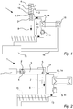
- Fig. 1 illustrates an embodiment of a slurry drying plant 1, as seen from the side.
- the slurry drying plant 1 comprises a vertically arranged slurry extruder 3 including conveying means 4 in the form of a screw conveyer.
- the conveying means 4 could also or instead comprise a conveying chain, a hydraulic or pneumatic piston or another mechanical device suitable for forcing slurry in the extruder 3 out of a plurality of exit openings 5 arranged at the exit end of a slurry extruder 3.
- the slurry extruder is provided with an opening disc 21 provided with a plurality of exit openings 5 so that when the slurry in the extruder 3 is forced against the opening disc 21 by means of the conveying means 4 the slurry is forced out through the exit openings 5 to form slurry string 7 hanging down into the underlying drying chamber 8.
- the opening disc 21 is interchangeable so that the opening disc 21 can be changed to an opening disc 21 with a different exit opening configuration - i.e. fewer/more holes, bigger/smaller holes, differently shaped holes and/or other - e.g. in dependence on slurry type, consistence, density or other or simply in response to wear.
- the extruder 3 would not comprise an opening disc 21 and the exit openings 5 would be formed permanently in the extruder structure.
- the slurry drying plant 1 further comprises slurry heating means 6 arranged to pass superheated steam past the slurry strings 7 in the drying chamber 8.
- the slurry heating means 6 is arranged to circulate steam through the drying chamber 8, through flow means 11, through steam heating means 14 and out into the drying chamber 8 again. I.e. in this embodiment at least some of the steam is circulating but in another embodiment, only little of the steam or even none of the steam would be circulating.
- the flow means 11 is arranged to direct the superheated steam flow through the drying chamber 8 in the same direction as the strings 7 are moving through the drying chamber 8.
- the steam could be arranged to flow in the opposite direction, it could be arranged to flow transversal to the direction of the strings and/or the drying chamber 8 could also or instead comprise more than one steam inlet 12 and/or more than one steam outlet 13.
- the flow means 11 does in this embodiment comprise an electrically powered blower but in another embodiment the steam flow could also or instead be generated by a fan, a pump, convection or other.
- the steam could also be guided through a cyclone device or a filtering device (not shown) arranged to catch impurities in the steam flow.
- the steam heating means 14 is formed by a heat exchanger providing heat to the steam from a succeeding thermal processing device 15 but in another embodiment the steam heating means 14 could also or instead comprise an electric heating device, a combustion heating device, a heat exchanger arranged to exchange heat with an external heat source or other.
- the slurry is entering the slurry drying plant 1 directly through the slurry inlet 2.
- the slurry drying plant 1 could further comprise a dewatering device (not shown) arranged to reduce the water content in the slurry before it enters the slurry inlet 2 e.g. to ensure that the solid matter content in the slurry is sufficiently high, to ensure that the viscosity of the slurry is sufficiently high, to ensure a more efficient drying process or other.
- the slurry drying plant 1 could further comprise a condensing device (not shown) through which the surplus steam is guided.
- the surplus steam is condensed at a temperature of around 100°C so that the generated heat can be used for facility heating, it can be used in other heat consuming processes, it can be supplied to an external district heating system or other.
- the condensing device would comprise several condensing steps to avoid clogging the condensing device with impurities in the steam.
- the dried slurry strings 7 leaving the drying chamber 8 could be stored, distributed on a field or other but in this embodiment, the slurry drying plant 1 further comprises a thermal processing device 15 which in this embodiment is arranged in direct succession of the drying chamber 8 so that the slurry is already hot when entering the thermal processing device 15.
- the thermal processing device 15 could be arranged distant from the drying chamber 8.
- the slurry entering the thermal processing device 15 would first passes through an airlock (not shown) ensuring that flue gasses and other does not escape back to the drying chamber 8.
- the dried slurry is in this embodiment put through a pyrolysis process.
- Pyrolysis is a thermochemical decomposition of the organic material in the slurry at elevated temperatures in the absence of oxygen (or any halogen) thereby charring the organic material. How much the temperatures have to be elevated is depending on the specific slurry but in this case the pyrolysis process takes place between 350°C and 1.200 °C.
- the pyrolysis process in the thermal processing device 15 generates highly combustible pyrolysis gasses which is lead to a combustion chamber (not shown) in which at least some of the gas is combusted during the supply of air.
- slurry drying plant 1 comprises heat transferring means 16 for transferring the very hot gas from the above-mentioned combustion process to the steam heating means 14 in which the heat is used for generating superheated steam.
- the steam heating means 14 and the heat transferring means 16 are the same heat exchanger but in another embodiment, these processes could at least partly take place separately.
- the thermal processing device 15 could also or instead be arranged to combust at least parts of the dried slurry so that the heat generated in this combustion process could be lead to the steam heating means 14 in which the heat is used for generating superheated steam.
- the slurry extruder 3 is further provided with a liquid separator which in this case is a sieve arranged in the extruder wall at the exit end so that when the conveying means have compressed the slurry to force it out of the exit openings 5 this compression will also press liquid out of the slurry through the sieve.
- a liquid separator which in this case is a sieve arranged in the extruder wall at the exit end so that when the conveying means have compressed the slurry to force it out of the exit openings 5 this compression will also press liquid out of the slurry through the sieve.
- Fig. 2 illustrates a slurry drying plant 1 comprising a horizontal extruder 3, as seen from the side.
- the slurry extruder 3 is arranged horizontally and the exit openings 5 is arranged in an underside of the sidewall of the extruder 3 so that the slurry strings 7 is hanging substantially vertically downwards when exiting the exit openings 5.
- the drying chamber 8 is formed as a cylindrical tube made from stainless steel.
- the drying chamber 8 could also or instead be made from ceramic, a non-stick surface material such as polytetrafluoroethylene (PTFE), anodized aluminium, silicone, enamelled cast iron or other and or the inside of the drying chamber 8 could comprise a cladding made from one or more of these materials.
- PTFE polytetrafluoroethylene
- Fig. 3 illustrates a slurry extruder 3, as seen from the bottom.
- the exit openings 5 are provided with a star shape to increase to surface area of the slurry strings 7 and in this embodiment, the plant 1 is provided with adjusting means 20 arranged to adjust the effective size of the exit openings 5.
- the adjusting means 20 is formed as a simple plate 22 arranged to be displaced in front of the exit openings 5 by means of an actuator 23.
- the adjusting means 20 could be formed by making the exit opening surroundings in a resilient material so that the exit openings 5 would expand in response to the slurry pressure.
- the slurry drying plant 1 is provided with an entrance pressure gauge 9 arranged to measure the pressure of the slurry at the slurry inlet 2 and an exit pressure gauge 10 arranged to measure the pressure of the slurry at the exit openings 5.
- an entrance pressure gauge 9 arranged to measure the pressure of the slurry at the slurry inlet 2
- an exit pressure gauge 10 arranged to measure the pressure of the slurry at the exit openings 5.
- only an entrance pressure gauge 9 or only an exit pressure gauge 10 would be provided or the plant 1 could be provided with more pressure gauges.
- the entrance pressure gauge 9 and the exit pressure gauge 10 are both connected to control means 17 so that data regarding the entrance pressure and the exit pressure of the slurry are delivered to the control means 17.
- the control means 17 is also connected to the motor 24 driving the conveying means 4 of the extruder 3 and to the actuator 23 of adjusting means 20, so that the operation of the extruder 3 and the adjusting means 20 may be controlled in response to measurements of the entrance pressure gauge 9 and/or the exit pressure gauge 10.
- only the motor 24 driving the conveying means 4 or only the adjusting means 20 would be controlled by the control means 17 or the control means could also or instead be arranged to control other parts of the plant 1 - such as a feed conveyer 19 (see fig. 4 ), the slurry heating means 6 and/or other in response to measurements of the entrance pressure gauge 9 and/or the exit pressure gauge 10.
- Fig. 4 illustrates a slurry extruder 3 and a feed conveyer 19, as seen from the front.
- a feed conveyer 19 is provided to convey slurry up into the slurry extruder 3 via the slurry inlet 2.
- the operation of the feed conveyer 19 is also controlled by the above-mentioned control means 17 in response to measurements of the entrance pressure gauge 9 and/or the exit pressure gauge 10.
Landscapes
- Engineering & Computer Science (AREA)
- Mechanical Engineering (AREA)
- General Engineering & Computer Science (AREA)
- Life Sciences & Earth Sciences (AREA)
- Microbiology (AREA)
- Drying Of Solid Materials (AREA)
Abstract
Disclosed is a slurry drying plant (1) comprising a slurry extruder (3) including conveying means (4) arranged to force the slurry out of a plurality of exit openings (5) of the slurry extruder (3) to form a plurality of slurry strings (7). The slurry strings (7) are forced out into a drying chamber (8) in which the plurality of slurry strings (7) are dried, and the slurry drying plant (1) also comprises slurry heating means (6) comprising flow means (11) for passing superheated steam substantially at atmospheric pressure past the slurry strings (7) in the drying chamber (8).
Furthermore, a method for drying slurry and use of a slurry drying plant (1) is disclosed.
Description
- The invention relates to a slurry drying plant comprising a slurry extruder including conveying means arranged to force the slurry out of a plurality of exit openings of the slurry extruder to form a plurality of slurry strings. The invention further relates to a method for drying slurry and use of a slurry drying plant.
- Organic slurry such as slurry from sewage treatment, farming, aquaculture, biochemical production, food production or other is problematic in that it is difficult and expensive to handle, store and dispose, it can contain drug residues, virus or other and it can emit bad smells or environmentally damaging gasses such as ammonium.
- A solution would be to dry the slurry to reduce or even substantially removed the water content of the slurry and thereby reduce or even completely eliminate the abovementioned problems.
- Thus, from the US patent application
WO 89/00888 A1 - It is therefore an object of the present invention to provide for a cost-efficient technique for drying slurry.
- The invention provides for slurry drying plant comprising a slurry extruder including conveying means arranged to force the slurry out of a plurality of exit openings of the slurry extruder to form a plurality of slurry strings. The slurry strings are forced out into a drying chamber in which the plurality of slurry strings are dried, and the slurry drying plant also comprises slurry heating means comprising flow means for passing superheated steam substantially at atmospheric pressure past the slurry strings in the drying chamber.
- Drying by means superheated steam substantially at atmospheric pressure is particularly advantageous in relation with drying slurry strings being forced out of a slurry extruder, in that no matter how uneven the strings are forced out of the extruder - i.e. uneven velocity, uneven density and/or other - the string cannot be dried so hard that they catch fire in that the superheated steam will displace any air and/or oxygen in the system and thereby inhibit any form of combustion. Thus, according to the present plant all the slurry string can be heated so hard that even the most dense and fast moving slurry strings will be dried sufficiently without risking that the slower moving and loose slurry strings will catch fire.
- Furthermore, when subsequently condensing the steam, the surplus heat can be reused in the slurry drying plant or e.g. fed to a central/district heating system.
- It should be emphasised that the term "slurry" is to be understood as any kind of organic liquid manure, fertilizer, sludge or similar liquids or semi-liquids in the form of a watery mixture of primarily insoluble matter i.e. a thick mixture of liquid and another at least substantially solid substance.
- Furthermore, in this context the term "slurry heating means" should be understood as any kind of heater, oven, furnace, boiler, heat exchanger, heat blower or other or any combination thereof or any other kind of slurry heater suitable for heating slurry by passing superheated steam substantially at atmospheric pressure past the slurry strings.
- It should also be emphasised that the term "flow means" is to be understood as any kind of piping, fan, blower, duct or similar or any combination thereof or any other kind of steam flow generator suitable for generating a steam flow past the slurry strings in the drying chamber.
- In an aspect of the invention, the exit openings are arranged to extrude the slurry downwards.
- Extruding the slurry strings downwards is advantageous in that it reduces the risk of the strings breaking before they are sufficiently dried. If they e.g. were extruded horizontally the force of gravity would pull them downwards and thereby increase the risk of breaking them.
- In an aspect of the invention, the conveying means is a screw conveyor.
- Screw conveyers are simple and efficient means for conveying and exerting a high pressure on a semi liquid substance.
- In an aspect of the invention, the flow means is arranged to guide the superheated steam flow past the slurry strings substantially in the same direction as the slurry strings are extruded.
- Guiding the superheated steam downstream is advantageous in that the slurry strings hereby will be dried the most as early as possible reducing the risk of strings comprising not sufficiently dried slurry breaking of. Also, if the steam was guided against the flow direction of the slurry strings the risk of light fragments being caught in the steam flow is increased - which could reduce the drying effect and increase the risk of premature string breakage.
- In an aspect of the invention, the drying plant comprises an entrance pressure gauge arranged to measure the pressure of the slurry at a slurry inlet of the slurry extruder.
- It is advantageous to measure the inlet slurry pressure in the extruder in that this measurement hereby can be used for operating the extruder or feed means arranged to feed the extruder more efficiently.
- In an aspect of the invention, the drying plant comprises an exit pressure gauge arranged to measure the pressure of the slurry at the exit openings.
- It is advantageous to measure the outlet slurry pressure in the extruder in that this measurement hereby can be used for ensuring a more unified string flow.
- In an aspect of the invention, the drying plant comprises control means arranged to control the operation of the slurry drying plant in response to input from the entrance pressure gauge and/or the exit pressure gauge.
- Hereby is achieved an advantageous embodiment of the invention.
- In this context, the term "control means" should be understood as any kind of controller capable of controlling the operation of at least parts of the drying plant - i.e. any kind of logic circuit, Programmable Logic Controller (PLC), computer or other.
- In an aspect of the invention, the flow means comprises means for circulating at least a part of said superheated steam.
- Circulating the superheated steam is advantageous in that it reduces energy consumption.
- In an aspect of the invention, the slurry heating means comprises steam heating means for heating the superheated steam to an entrance temperature of between 110°C and 400°C, preferably between 130°C and 300°C and most preferred between 150°C and 250°C.
- If the entrance temperature - i.e. the temperature of the steam when it enters the drying chamber and first comes in contact with the slurry - of the superheated steam is too high a torrefaction or pyrolysis process will commence, thus generating highly flammable gasses, poisonous gasses or other dangerous or damaging by-products which are not easy to handle when mixed the superheated steam. However, if the entrance temperature is too low the drying process will be inefficient and the capacity of the slurry drying plant is reduced. Thus, the present temperature ranges present an advantageous relationship between safety and efficiency.
- It should be emphasised that the term "steam heating means" is to be understood as any kind of heat exchanger, boiler, heat pump or other or any other kind of steam heater suitable for heating steam in a slurry drying plant.
- In an aspect of the invention, the slurry drying plant further comprises a subsequent thermal processing device in which slurry leaving the drying chamber is burned or pyrolyzed.
- Subsequently putting the dried slurry through a combustion process or a pyrolysis process is advantageous in that the slurry hereby can be reduced to substantially harmless coke which is free from virus and drug residues and therefore can be used as fertilizer. Furthermore, the coke is easy to handle and store.
- And it is advantageous to conduct this combustion process or pyrolysis process in a subsequent substantially separate thermal processing device in that the flue gas or other generated gasses can be easier and more efficiently handled when being separate from the superheated steam.
- It should be noted that in this context the term "pyrolysis process" or "pyrolysed" also covers torrefaction which is a mild form of pyrolysis at temperatures typically between 200 and 320 °C depending on the specific slurry.
- In an aspect of the invention, the slurry drying plant further comprises heat transferring means for transferring heat generated in or by the subsequent thermal processing device to the superheated steam.
- A subsequent combustion process or pyrolysis process will generate much heat (when burning the flammable gasses generated in the pyrolysis process). And since producing the superheated steam requires much heat it is advantageous to transfer the generated heat and thereby reduce or avoid consumption of external power to generate the superheated steam.
- It should be emphasised that the term "heat transferring means" is to be understood as any kind of heat exchanger, piping, blower or other or any combination thereof or any other kind of heat transferor suited for transferring heat generated in or by the subsequent thermal processing device to the superheated steam.
- In an aspect of the invention, a liquid separator is arranged in the slurry extruder before the exit openings.
- A relatively high pressure will have to be generated in the slurry extruder to ensure that the slurry strings are formed correctly. It is therefore advantageous to use this high pressure to drain the slurry for any excess liquid.
- In an aspect of the invention, the liquid separator comprises at least one sieve.
- Forming the liquid separator as a sieve is advantageous in that a sieve is a simple way of ensuring that only liquid leaves the extruder through the liquid separator.
- In an aspect of the invention, the exit openings are formed to increase the surface area of the slurry strings.
- Forming the exit openings with a star shape, a rectangular shape, a wavy shape or a similar complex shape that will increase the surface area of the slurry strings is advantageous in that the strings hereby can be dried more efficiently and fast.
- In an aspect of the invention, the slurry drying plant comprises a feed conveyer arranged to feed the slurry into the slurry extruder.
- Hereby is achieved an advantageous embodiment of the invention.
- In an aspect of the invention, the slurry has been drained before entering the slurry extruder.
- If the slurry is too wet before entering the slurry extruder it can be difficult to form sufficiently coherent strings and it is therefore advantageous to drain the slurry before it enters the extruder.
- In an aspect of the invention, the slurry drying plant comprises a dewatering device arranged to reduce the water content in the slurry before it enters the slurry inlet.
- In an aspect of the invention, an inside surface of the drying chamber is provided with a non-stick surface such as polytetrafluoroethylene (PTFE), anodized aluminium, ceramics, silicone, enamelled cast iron, or stainless steel.
- Forming the drying chamber with a non-stick inner surface is advantageous in that it will reduce the risk of slurry burning onto the surface.
- In an aspect of the invention, the slurry extruder comprises adjusting means for adjusting the size of at least some of the exit openings.
- Providing adjusting means is advantageous in that it will enable a more versatile extruder more suited for different slurry types.
- It should be noted that in this context the term "adjusting means" should be understood as any kind of resilient material forming the openings, any kind of mechanical opening size adjuster or any other kind of adjuster suitable for adjusting the size of at least some of the exit openings.
- In an aspect of the invention, the slurry extruder comprises adjusting means for adjusting the size of at least some of the exit openings in response to a slurry pressure inside the slurry extruder.
- Controlling the opening sizes in relation to the pressure in the extruder is advantageous in that it enables a more efficient extruder process.
- The invention provides further for method for drying slurry, the method comprising the steps of:
- conveying the slurry through a slurry extruder to force the slurry out of a plurality of exit openings of the slurry extruder to form a plurality of slurry strings,
- drying the slurry strings by guiding superheated steam substantially at atmospheric pressure past the slurry strings.
- Extruding the slurry provides the slurry with a large surface area which will enable an efficient drying process and drying the strings by means of superheated steam is advantageous in that it ensures a fast and efficient drying process where the risk of the strings catching fire due to overheating is eliminated.
- In an aspect of the invention, a binding agent is added to the slurry before the slurry is forced out of the plurality of exit openings.
- Adding a binding agent to the slurry is advantageous in that a binding agent will help in forming continuous slurry string that will be dried more before breaking off.
- In an aspect of the invention, the method is performed by means of a slurry drying plant according to any of the previously discussed slurry drying plants.
- In an aspect of the invention, the method further comprises the step of leading slurry from the exit openings to a subsequent thermal processing device in which the slurry will be burned or pyrolysed.
- Subsequently processing the slurry in a thermal processing device is advantageous in that this process hereby can run separately from the initial drying process.
- In an aspect of the invention, the method further comprises the step of transferring heat generated in or by the subsequent thermal processing device to the superheated steam.
- By utilizing the generated heat in the drying process a very energy efficient slurry drying plant and method is provided.
- The invention also provides for use of a slurry drying plant according to any of the previously discussed slurry drying plants for drying slurry having a solid matter content above 2%, preferably above 5% and most preferred above 10%.
- If the solid matter content in the slurry is too low the slurry is difficult to handle in the screw conveyers and it is therefore advantageous to ensure that the solid matter content of the slurry is above a certain level to ensure that the viscosity of the slurry is sufficiently high.
- The invention will be described in the following with reference to the figures in which
- fig. 1.
- illustrates a slurry drying plant comprising a vertical extruder, as seen from the side,
- fig. 2
- illustrates a slurry drying plant comprising a horizontal extruder, as seen from the side,
- fig. 3
- illustrates a slurry extruder, as seen from the bottom, and
- fig. 4
- illustrates a slurry extruder and a feed conveyer, as seen from the front.
-
Fig. 1 illustrates an embodiment of aslurry drying plant 1, as seen from the side. - In this embodiment, the
slurry drying plant 1 comprises a vertically arrangedslurry extruder 3 including conveyingmeans 4 in the form of a screw conveyer. However, in another embodiment, the conveyingmeans 4 could also or instead comprise a conveying chain, a hydraulic or pneumatic piston or another mechanical device suitable for forcing slurry in theextruder 3 out of a plurality ofexit openings 5 arranged at the exit end of aslurry extruder 3. - In this embodiment, the slurry extruder is provided with an opening disc 21 provided with a plurality of
exit openings 5 so that when the slurry in theextruder 3 is forced against the opening disc 21 by means of the conveyingmeans 4 the slurry is forced out through theexit openings 5 to formslurry string 7 hanging down into theunderlying drying chamber 8. In this embodiment, the opening disc 21 is interchangeable so that the opening disc 21 can be changed to an opening disc 21 with a different exit opening configuration - i.e. fewer/more holes, bigger/smaller holes, differently shaped holes and/or other - e.g. in dependence on slurry type, consistence, density or other or simply in response to wear. However, in another embodiment theextruder 3 would not comprise an opening disc 21 and theexit openings 5 would be formed permanently in the extruder structure. - The
slurry drying plant 1 further comprises slurry heating means 6 arranged to pass superheated steam past theslurry strings 7 in the dryingchamber 8. In this embodiment, the slurry heating means 6 is arranged to circulate steam through the dryingchamber 8, through flow means 11, through steam heating means 14 and out into the dryingchamber 8 again. I.e. in this embodiment at least some of the steam is circulating but in another embodiment, only little of the steam or even none of the steam would be circulating. - In this embodiment, the flow means 11 is arranged to direct the superheated steam flow through the drying
chamber 8 in the same direction as thestrings 7 are moving through the dryingchamber 8. But in another embodiment, the steam could be arranged to flow in the opposite direction, it could be arranged to flow transversal to the direction of the strings and/or the dryingchamber 8 could also or instead comprise more than onesteam inlet 12 and/or more than onesteam outlet 13. - Besides the
steam inlet 12 and thesteam outlet 13 the flow means 11 does in this embodiment comprise an electrically powered blower but in another embodiment the steam flow could also or instead be generated by a fan, a pump, convection or other. - In another embodiment, the steam could also be guided through a cyclone device or a filtering device (not shown) arranged to catch impurities in the steam flow.
- In this embodiment, the steam heating means 14 is formed by a heat exchanger providing heat to the steam from a succeeding
thermal processing device 15 but in another embodiment the steam heating means 14 could also or instead comprise an electric heating device, a combustion heating device, a heat exchanger arranged to exchange heat with an external heat source or other. - In this embodiment, the slurry is entering the
slurry drying plant 1 directly through theslurry inlet 2. However, in another embodiment theslurry drying plant 1 could further comprise a dewatering device (not shown) arranged to reduce the water content in the slurry before it enters theslurry inlet 2 e.g. to ensure that the solid matter content in the slurry is sufficiently high, to ensure that the viscosity of the slurry is sufficiently high, to ensure a more efficient drying process or other. - As the slurry constantly will generate more steam during the drying process through evaporation, surplus steam is constantly generated. The surplus steam could be lead out of the system by means of a pressure control valve, a safety valve or some other discharge arrangement or in another embodiment the
slurry drying plant 1 could further comprise a condensing device (not shown) through which the surplus steam is guided. In such a condensing device, the surplus steam is condensed at a temperature of around 100°C so that the generated heat can be used for facility heating, it can be used in other heat consuming processes, it can be supplied to an external district heating system or other. In a preferred embodiment, the condensing device would comprise several condensing steps to avoid clogging the condensing device with impurities in the steam. - The dried
slurry strings 7 leaving the dryingchamber 8 could be stored, distributed on a field or other but in this embodiment, theslurry drying plant 1 further comprises athermal processing device 15 which in this embodiment is arranged in direct succession of the dryingchamber 8 so that the slurry is already hot when entering thethermal processing device 15. However, in another embodiment thethermal processing device 15 could be arranged distant from the dryingchamber 8. - In another embodiment, the slurry entering the
thermal processing device 15 would first passes through an airlock (not shown) ensuring that flue gasses and other does not escape back to the dryingchamber 8. - In the
thermal processing device 15 the dried slurry is in this embodiment put through a pyrolysis process. Pyrolysis is a thermochemical decomposition of the organic material in the slurry at elevated temperatures in the absence of oxygen (or any halogen) thereby charring the organic material. How much the temperatures have to be elevated is depending on the specific slurry but in this case the pyrolysis process takes place between 350°C and 1.200 °C. - The pyrolysis process in the
thermal processing device 15 generates highly combustible pyrolysis gasses which is lead to a combustion chamber (not shown) in which at least some of the gas is combusted during the supply of air. - In this embodiment
slurry drying plant 1 comprises heat transferring means 16 for transferring the very hot gas from the above-mentioned combustion process to the steam heating means 14 in which the heat is used for generating superheated steam. In this embodiment, the steam heating means 14 and the heat transferring means 16 are the same heat exchanger but in another embodiment, these processes could at least partly take place separately. - In another embodiment, the
thermal processing device 15 could also or instead be arranged to combust at least parts of the dried slurry so that the heat generated in this combustion process could be lead to the steam heating means 14 in which the heat is used for generating superheated steam. - In this embodiment, the
slurry extruder 3 is further provided with a liquid separator which in this case is a sieve arranged in the extruder wall at the exit end so that when the conveying means have compressed the slurry to force it out of theexit openings 5 this compression will also press liquid out of the slurry through the sieve. -
Fig. 2 illustrates aslurry drying plant 1 comprising ahorizontal extruder 3, as seen from the side. - In this embodiment, the
slurry extruder 3 is arranged horizontally and theexit openings 5 is arranged in an underside of the sidewall of theextruder 3 so that the slurry strings 7 is hanging substantially vertically downwards when exiting theexit openings 5. - In this embodiment, the drying
chamber 8 is formed as a cylindrical tube made from stainless steel. However, in another embodiment the dryingchamber 8 could also or instead be made from ceramic, a non-stick surface material such as polytetrafluoroethylene (PTFE), anodized aluminium, silicone, enamelled cast iron or other and or the inside of the dryingchamber 8 could comprise a cladding made from one or more of these materials. -
Fig. 3 illustrates aslurry extruder 3, as seen from the bottom. - In this embodiment, the
exit openings 5 are provided with a star shape to increase to surface area of theslurry strings 7 and in this embodiment, theplant 1 is provided with adjusting means 20 arranged to adjust the effective size of theexit openings 5. In this embodiment, the adjusting means 20 is formed as a simple plate 22 arranged to be displaced in front of theexit openings 5 by means of anactuator 23. However, in another embodiment the adjusting means 20 could be formed by making the exit opening surroundings in a resilient material so that theexit openings 5 would expand in response to the slurry pressure. - In this embodiment, the
slurry drying plant 1 is provided with an entrance pressure gauge 9 arranged to measure the pressure of the slurry at theslurry inlet 2 and anexit pressure gauge 10 arranged to measure the pressure of the slurry at theexit openings 5. However, in another embodiment only an entrance pressure gauge 9 or only anexit pressure gauge 10 would be provided or theplant 1 could be provided with more pressure gauges. - In this embodiment, the entrance pressure gauge 9 and the
exit pressure gauge 10 are both connected to control means 17 so that data regarding the entrance pressure and the exit pressure of the slurry are delivered to the control means 17. In this embodiment, the control means 17 is also connected to themotor 24 driving the conveyingmeans 4 of theextruder 3 and to theactuator 23 of adjusting means 20, so that the operation of theextruder 3 and the adjusting means 20 may be controlled in response to measurements of the entrance pressure gauge 9 and/or theexit pressure gauge 10. - In another embodiment, only the
motor 24 driving the conveyingmeans 4 or only the adjusting means 20 would be controlled by the control means 17 or the control means could also or instead be arranged to control other parts of the plant 1 - such as a feed conveyer 19 (seefig. 4 ), the slurry heating means 6 and/or other in response to measurements of the entrance pressure gauge 9 and/or theexit pressure gauge 10. -
Fig. 4 illustrates aslurry extruder 3 and afeed conveyer 19, as seen from the front. - In this embodiment, a
feed conveyer 19 is provided to convey slurry up into theslurry extruder 3 via theslurry inlet 2. In an embodiment of the invention the operation of thefeed conveyer 19 is also controlled by the above-mentioned control means 17 in response to measurements of the entrance pressure gauge 9 and/or theexit pressure gauge 10. - The invention has been exemplified above with reference to specific examples of
slurry drying plant 1,slurry extruders 3, slurry heating means 6 and other. However, it should be understood that the invention is not limited to the particular examples described above but may be designed and altered in a multitude of varieties within the scope of the invention as specified in the claims. -
- 1. Slurry drying plant
- 2. Slurry inlet
- 3. Slurry extruder
- 4. Conveying means
- 5. Exit openings
- 6. Slurry heating means
- 7. Slurry strings
- 8. Drying chamber
- 9. Entrance pressure gauge
- 10. Exit pressure gauge
- 11. Flow means
- 12. Steam inlet
- 13. Steam outlet
- 14. Steam heating means
- 15. Thermal processing device
- 16. Heat transferring means
- 17. Control means
- 18. Liquid separator
- 19. Feed conveyer
- 20. Adjusting means
- 21. Opening disc
- 22. Plate
- 23. Actuator
- 24. Motor
Claims (15)
- A slurry drying plant (1) comprising
a slurry extruder (3) including conveying means (4) arranged to force said slurry out of a plurality of exit openings (5) of said slurry extruder (3) to form a plurality of slurry strings (7), wherein said slurry strings (7) are forced out into
a drying chamber (8) in which said plurality of slurry strings (7) are dried, and
slurry heating means (6) comprising flow means (11) for passing superheated steam substantially at atmospheric pressure past said slurry strings (7) in said drying chamber (8). - A slurry drying plant (1) according to claim 1, wherein said flow means (11) is arranged to guide said superheated steam flow past said slurry strings (7) substantially in the same direction as the slurry strings (7) are extruded.
- A slurry drying plant (1) according to claim 1 or 2, wherein said drying plant (1) comprises an entrance pressure gauge (9) arranged to measure the pressure of said slurry at a slurry inlet (2) of said slurry extruder (3).
- A slurry drying plant (1) according to any of the preceding claims, wherein said drying plant (1) comprises an exit pressure gauge (10) arranged to measure the pressure of said slurry at said exit openings (5).
- A slurry drying plant (1) according to any of the preceding claims 3 or 4, wherein said drying plant (1) comprises control means (17) arranged to control the operation of said slurry drying plant (1) in response to input from said entrance pressure gauge (9) and/or said exit pressure gauge (10).
- A slurry drying plant (1) according to any of the preceding claims, wherein a liquid separator (18) is arranged in said slurry extruder (3) before said exit openings (5).
- A slurry drying plant (1) according to claim 10, wherein said liquid separator (18) comprises at least one sieve.
- A slurry drying plant (1) according to any of the preceding claims, wherein said exit openings (5) are formed to increase the surface area of said slurry strings (7).
- A slurry drying plant (1) according to any of the preceding claims, wherein an inside surface of said drying chamber (8) is provided with a non-stick surface such as polytetrafluoroethylene (PTFE), anodized aluminium, ceramics, silicone, enamelled cast iron, or stainless steel.
- A slurry drying plant (1) according to any of the preceding claims, wherein said slurry extruder (3) comprises adjusting means (20) for adjusting the size of at least some of said exit openings (5).
- A slurry drying plant (1) according claim 10, wherein said slurry extruder (3) comprises adjusting means (20) for adjusting the size of at least some of said exit openings (5) in response to a slurry pressure inside said slurry extruder (3).
- A method for drying slurry, said method comprising the steps of:• conveying said slurry through a slurry extruder (3) to force said slurry out of a plurality of exit openings (5) of said slurry extruder (3) to form a plurality of slurry strings (7),• drying said slurry strings (7) by guiding superheated steam substantially at atmospheric pressure past said slurry strings (7).
- method according to claim 12, wherein a binding agent is added to said slurry before said slurry is forced out of said plurality of exit openings (5).
- method according to claim 12 or 13, wherein said method is performed by means of a slurry drying plant (1) according to any of claims 1-10.
- Use of a slurry drying plant (1) according to any of claims 1-10 for drying slurry having a solid matter content above 2%, preferably above 5% and most preferred above 10%.
Priority Applications (1)
| Application Number | Priority Date | Filing Date | Title |
|---|---|---|---|
| EP17178463.0A EP3421913A1 (en) | 2017-06-28 | 2017-06-28 | A slurry drying plant, a method for drying slurry and use of a slurry drying plant |
Applications Claiming Priority (1)
| Application Number | Priority Date | Filing Date | Title |
|---|---|---|---|
| EP17178463.0A EP3421913A1 (en) | 2017-06-28 | 2017-06-28 | A slurry drying plant, a method for drying slurry and use of a slurry drying plant |
Publications (1)
| Publication Number | Publication Date |
|---|---|
| EP3421913A1 true EP3421913A1 (en) | 2019-01-02 |
Family
ID=59253407
Family Applications (1)
| Application Number | Title | Priority Date | Filing Date |
|---|---|---|---|
| EP17178463.0A Withdrawn EP3421913A1 (en) | 2017-06-28 | 2017-06-28 | A slurry drying plant, a method for drying slurry and use of a slurry drying plant |
Country Status (1)
| Country | Link |
|---|---|
| EP (1) | EP3421913A1 (en) |
Cited By (1)
| Publication number | Priority date | Publication date | Assignee | Title |
|---|---|---|---|---|
| WO2020088719A1 (en) * | 2018-11-01 | 2020-05-07 | Danmarks Tekniske Universitet | A slurry drying plant, a method for drying slurry and use of a slurry drying plant |
Citations (4)
| Publication number | Priority date | Publication date | Assignee | Title |
|---|---|---|---|---|
| US3348599A (en) * | 1964-04-03 | 1967-10-24 | Scientism Lab | Apparatus for dewatering and dehydrating slimes and the like |
| WO1989000888A1 (en) | 1987-07-27 | 1989-02-09 | Vølund Miljøteknik A/S | An apparatus for extruding and drying moist bulk material, e.g. organic waste material |
| EP1343710A1 (en) * | 2000-11-08 | 2003-09-17 | Fortum OYJ | Method and apparatus for feeding sludge into a process |
| KR101306083B1 (en) * | 2010-08-31 | 2013-09-09 | 주식회사쿡웰 | System for drying sludge using superheated vapor |
-
2017
- 2017-06-28 EP EP17178463.0A patent/EP3421913A1/en not_active Withdrawn
Patent Citations (4)
| Publication number | Priority date | Publication date | Assignee | Title |
|---|---|---|---|---|
| US3348599A (en) * | 1964-04-03 | 1967-10-24 | Scientism Lab | Apparatus for dewatering and dehydrating slimes and the like |
| WO1989000888A1 (en) | 1987-07-27 | 1989-02-09 | Vølund Miljøteknik A/S | An apparatus for extruding and drying moist bulk material, e.g. organic waste material |
| EP1343710A1 (en) * | 2000-11-08 | 2003-09-17 | Fortum OYJ | Method and apparatus for feeding sludge into a process |
| KR101306083B1 (en) * | 2010-08-31 | 2013-09-09 | 주식회사쿡웰 | System for drying sludge using superheated vapor |
Cited By (2)
| Publication number | Priority date | Publication date | Assignee | Title |
|---|---|---|---|---|
| WO2020088719A1 (en) * | 2018-11-01 | 2020-05-07 | Danmarks Tekniske Universitet | A slurry drying plant, a method for drying slurry and use of a slurry drying plant |
| US12078416B2 (en) | 2018-11-01 | 2024-09-03 | Danmarks Tekniske Universitet | Slurry drying plant, a method for drying slurry and use of a slurry drying plant |
Similar Documents
| Publication | Publication Date | Title |
|---|---|---|
| EP3580509B1 (en) | A slurry drying plant, a method for drying slurry and use of a slurry drying plant | |
| NL1030864C2 (en) | Method and device for treating biomass. | |
| JP5118058B2 (en) | Apparatus for heat treating organic materials and method therefor | |
| JP6899332B2 (en) | Pyrolysis equipment and method | |
| CN102985513A (en) | Apparatus and method for drying and torrefaction of at least one carbonaceous stream in a multi-bed furnace | |
| EP2789677A1 (en) | Torrefaction plant, its operation and maintenance | |
| CN103608435A (en) | Method of torrefaction of a biomass comprising the step of cooling the torrefaction reaction | |
| FI125541B (en) | Torrefieringsanordning | |
| CZ2007475A3 (en) | Equipment for drying loose and slurries and sludge | |
| RU2508503C2 (en) | Operating method of bioethanol production unit | |
| EP3874214B1 (en) | A slurry drying plant, a method for drying slurry and use of a slurry drying plant | |
| US20160017233A1 (en) | System and Method for Pyrolysis of a Biomass | |
| KR20140035236A (en) | Drying apparatus and the drying method of it | |
| KR101797431B1 (en) | Multi-Pass Continuous type High-moisture waste and biomass dryer | |
| CN111836786A (en) | System and method for thermal drying for environmental cleaning | |
| JP2010084053A (en) | Carbonized material producing apparatus | |
| RU2468061C2 (en) | Plant for production of charcoal | |
| JP2009138089A (en) | Multistage screw carbonization device | |
| GB2188916A (en) | Method and apparatus for producing charcoal | |
| RU2613063C2 (en) | Zolotarev pyrolysis reactor | |
| CA2767625A1 (en) | An apparatus for thermally treating organic material and method for using the apparatus | |
| RU2555892C1 (en) | Activation and regeneration unit | |
| JP2011001432A (en) | Screw type carbonization furnace | |
| WO2022198302A1 (en) | Low-temperature, ejector assisted dryer apparatus, methods and deployment thereof | |
| JPH039990A (en) | Carbonization of organic solid |
Legal Events
| Date | Code | Title | Description |
|---|---|---|---|
| PUAI | Public reference made under article 153(3) epc to a published international application that has entered the european phase |
Free format text: ORIGINAL CODE: 0009012 |
|
| AK | Designated contracting states |
Kind code of ref document: A1 Designated state(s): AL AT BE BG CH CY CZ DE DK EE ES FI FR GB GR HR HU IE IS IT LI LT LU LV MC MK MT NL NO PL PT RO RS SE SI SK SM TR |
|
| AX | Request for extension of the european patent |
Extension state: BA ME |
|
| RAP1 | Party data changed (applicant data changed or rights of an application transferred) |
Owner name: AQUAGREEN LICENSE APS Owner name: DANMARKS TEKNISKE UNIVERSITET |
|
| STAA | Information on the status of an ep patent application or granted ep patent |
Free format text: STATUS: THE APPLICATION IS DEEMED TO BE WITHDRAWN |
|
| 18D | Application deemed to be withdrawn |
Effective date: 20190703 |