EP3421861A1 - Motion stabilization on a motorized monopod jib - Google Patents
Motion stabilization on a motorized monopod jib Download PDFInfo
- Publication number
- EP3421861A1 EP3421861A1 EP18178234.3A EP18178234A EP3421861A1 EP 3421861 A1 EP3421861 A1 EP 3421861A1 EP 18178234 A EP18178234 A EP 18178234A EP 3421861 A1 EP3421861 A1 EP 3421861A1
- Authority
- EP
- European Patent Office
- Prior art keywords
- motors
- adjustment value
- jib
- camera
- displacement event
- Prior art date
- Legal status (The legal status is an assumption and is not a legal conclusion. Google has not performed a legal analysis and makes no representation as to the accuracy of the status listed.)
- Granted
Links
Images





Classifications
-
- B—PERFORMING OPERATIONS; TRANSPORTING
- B25—HAND TOOLS; PORTABLE POWER-DRIVEN TOOLS; MANIPULATORS
- B25J—MANIPULATORS; CHAMBERS PROVIDED WITH MANIPULATION DEVICES
- B25J9/00—Program-controlled manipulators
- B25J9/16—Program controls
- B25J9/1628—Program controls characterised by the control loop
- B25J9/1638—Program controls characterised by the control loop compensation for arm bending/inertia, pay load weight/inertia
-
- B—PERFORMING OPERATIONS; TRANSPORTING
- B25—HAND TOOLS; PORTABLE POWER-DRIVEN TOOLS; MANIPULATORS
- B25J—MANIPULATORS; CHAMBERS PROVIDED WITH MANIPULATION DEVICES
- B25J9/00—Program-controlled manipulators
- B25J9/16—Program controls
- B25J9/1612—Program controls characterised by the hand, wrist, grip control
-
- B—PERFORMING OPERATIONS; TRANSPORTING
- B25—HAND TOOLS; PORTABLE POWER-DRIVEN TOOLS; MANIPULATORS
- B25J—MANIPULATORS; CHAMBERS PROVIDED WITH MANIPULATION DEVICES
- B25J9/00—Program-controlled manipulators
- B25J9/10—Program-controlled manipulators characterised by positioning means for manipulator elements
- B25J9/12—Program-controlled manipulators characterised by positioning means for manipulator elements electric
- B25J9/126—Rotary actuators
-
- B—PERFORMING OPERATIONS; TRANSPORTING
- B25—HAND TOOLS; PORTABLE POWER-DRIVEN TOOLS; MANIPULATORS
- B25J—MANIPULATORS; CHAMBERS PROVIDED WITH MANIPULATION DEVICES
- B25J9/00—Program-controlled manipulators
- B25J9/16—Program controls
- B25J9/1628—Program controls characterised by the control loop
- B25J9/1633—Program controls characterised by the control loop compliant, force, torque control, e.g. combined with position control
-
- B—PERFORMING OPERATIONS; TRANSPORTING
- B25—HAND TOOLS; PORTABLE POWER-DRIVEN TOOLS; MANIPULATORS
- B25J—MANIPULATORS; CHAMBERS PROVIDED WITH MANIPULATION DEVICES
- B25J9/00—Program-controlled manipulators
- B25J9/16—Program controls
- B25J9/1628—Program controls characterised by the control loop
- B25J9/1635—Program controls characterised by the control loop flexible-arm control
-
- F—MECHANICAL ENGINEERING; LIGHTING; HEATING; WEAPONS; BLASTING
- F16—ENGINEERING ELEMENTS AND UNITS; GENERAL MEASURES FOR PRODUCING AND MAINTAINING EFFECTIVE FUNCTIONING OF MACHINES OR INSTALLATIONS; THERMAL INSULATION IN GENERAL
- F16M—FRAMES, CASINGS OR BEDS OF ENGINES, MACHINES OR APPARATUS, NOT SPECIFIC TO ENGINES, MACHINES OR APPARATUS PROVIDED FOR ELSEWHERE; STANDS; SUPPORTS
- F16M11/00—Stands or trestles as supports for apparatus or articles placed thereon ; Stands for scientific apparatus such as gravitational force meters
- F16M11/02—Heads
- F16M11/04—Means for attachment of apparatus; Means allowing adjustment of the apparatus relatively to the stand
- F16M11/06—Means for attachment of apparatus; Means allowing adjustment of the apparatus relatively to the stand allowing pivoting
-
- F—MECHANICAL ENGINEERING; LIGHTING; HEATING; WEAPONS; BLASTING
- F16—ENGINEERING ELEMENTS AND UNITS; GENERAL MEASURES FOR PRODUCING AND MAINTAINING EFFECTIVE FUNCTIONING OF MACHINES OR INSTALLATIONS; THERMAL INSULATION IN GENERAL
- F16M—FRAMES, CASINGS OR BEDS OF ENGINES, MACHINES OR APPARATUS, NOT SPECIFIC TO ENGINES, MACHINES OR APPARATUS PROVIDED FOR ELSEWHERE; STANDS; SUPPORTS
- F16M11/00—Stands or trestles as supports for apparatus or articles placed thereon ; Stands for scientific apparatus such as gravitational force meters
- F16M11/02—Heads
- F16M11/04—Means for attachment of apparatus; Means allowing adjustment of the apparatus relatively to the stand
- F16M11/06—Means for attachment of apparatus; Means allowing adjustment of the apparatus relatively to the stand allowing pivoting
- F16M11/12—Means for attachment of apparatus; Means allowing adjustment of the apparatus relatively to the stand allowing pivoting in more than one direction
- F16M11/121—Means for attachment of apparatus; Means allowing adjustment of the apparatus relatively to the stand allowing pivoting in more than one direction constituted of several dependent joints
- F16M11/123—Means for attachment of apparatus; Means allowing adjustment of the apparatus relatively to the stand allowing pivoting in more than one direction constituted of several dependent joints the axis of rotation intersecting in a single point, e.g. by using gimbals
-
- F—MECHANICAL ENGINEERING; LIGHTING; HEATING; WEAPONS; BLASTING
- F16—ENGINEERING ELEMENTS AND UNITS; GENERAL MEASURES FOR PRODUCING AND MAINTAINING EFFECTIVE FUNCTIONING OF MACHINES OR INSTALLATIONS; THERMAL INSULATION IN GENERAL
- F16M—FRAMES, CASINGS OR BEDS OF ENGINES, MACHINES OR APPARATUS, NOT SPECIFIC TO ENGINES, MACHINES OR APPARATUS PROVIDED FOR ELSEWHERE; STANDS; SUPPORTS
- F16M11/00—Stands or trestles as supports for apparatus or articles placed thereon ; Stands for scientific apparatus such as gravitational force meters
- F16M11/02—Heads
- F16M11/18—Heads with mechanism for moving the apparatus relatively to the stand
-
- F—MECHANICAL ENGINEERING; LIGHTING; HEATING; WEAPONS; BLASTING
- F16—ENGINEERING ELEMENTS AND UNITS; GENERAL MEASURES FOR PRODUCING AND MAINTAINING EFFECTIVE FUNCTIONING OF MACHINES OR INSTALLATIONS; THERMAL INSULATION IN GENERAL
- F16M—FRAMES, CASINGS OR BEDS OF ENGINES, MACHINES OR APPARATUS, NOT SPECIFIC TO ENGINES, MACHINES OR APPARATUS PROVIDED FOR ELSEWHERE; STANDS; SUPPORTS
- F16M13/00—Other supports for positioning apparatus or articles; Means for steadying hand-held apparatus or articles
-
- F—MECHANICAL ENGINEERING; LIGHTING; HEATING; WEAPONS; BLASTING
- F16—ENGINEERING ELEMENTS AND UNITS; GENERAL MEASURES FOR PRODUCING AND MAINTAINING EFFECTIVE FUNCTIONING OF MACHINES OR INSTALLATIONS; THERMAL INSULATION IN GENERAL
- F16M—FRAMES, CASINGS OR BEDS OF ENGINES, MACHINES OR APPARATUS, NOT SPECIFIC TO ENGINES, MACHINES OR APPARATUS PROVIDED FOR ELSEWHERE; STANDS; SUPPORTS
- F16M13/00—Other supports for positioning apparatus or articles; Means for steadying hand-held apparatus or articles
- F16M13/02—Other supports for positioning apparatus or articles; Means for steadying hand-held apparatus or articles for supporting on, or attaching to, an object, e.g. tree, gate, window-frame, cycle
-
- F—MECHANICAL ENGINEERING; LIGHTING; HEATING; WEAPONS; BLASTING
- F16—ENGINEERING ELEMENTS AND UNITS; GENERAL MEASURES FOR PRODUCING AND MAINTAINING EFFECTIVE FUNCTIONING OF MACHINES OR INSTALLATIONS; THERMAL INSULATION IN GENERAL
- F16M—FRAMES, CASINGS OR BEDS OF ENGINES, MACHINES OR APPARATUS, NOT SPECIFIC TO ENGINES, MACHINES OR APPARATUS PROVIDED FOR ELSEWHERE; STANDS; SUPPORTS
- F16M13/00—Other supports for positioning apparatus or articles; Means for steadying hand-held apparatus or articles
- F16M13/04—Other supports for positioning apparatus or articles; Means for steadying hand-held apparatus or articles for supporting on, or holding steady relative to, a person, e.g. by chains, e.g. rifle butt or pistol grip supports, supports attached to the chest or head
-
- G—PHYSICS
- G03—PHOTOGRAPHY; CINEMATOGRAPHY; ANALOGOUS TECHNIQUES USING WAVES OTHER THAN OPTICAL WAVES; ELECTROGRAPHY; HOLOGRAPHY
- G03B—APPARATUS OR ARRANGEMENTS FOR TAKING PHOTOGRAPHS OR FOR PROJECTING OR VIEWING THEM; APPARATUS OR ARRANGEMENTS EMPLOYING ANALOGOUS TECHNIQUES USING WAVES OTHER THAN OPTICAL WAVES; ACCESSORIES THEREFOR
- G03B17/00—Details of cameras or camera bodies; Accessories therefor
- G03B17/56—Accessories
- G03B17/561—Support related camera accessories
-
- F—MECHANICAL ENGINEERING; LIGHTING; HEATING; WEAPONS; BLASTING
- F16—ENGINEERING ELEMENTS AND UNITS; GENERAL MEASURES FOR PRODUCING AND MAINTAINING EFFECTIVE FUNCTIONING OF MACHINES OR INSTALLATIONS; THERMAL INSULATION IN GENERAL
- F16M—FRAMES, CASINGS OR BEDS OF ENGINES, MACHINES OR APPARATUS, NOT SPECIFIC TO ENGINES, MACHINES OR APPARATUS PROVIDED FOR ELSEWHERE; STANDS; SUPPORTS
- F16M2200/00—Details of stands or supports
- F16M2200/04—Balancing means
- F16M2200/041—Balancing means for balancing rotational movement of the head
-
- Y—GENERAL TAGGING OF NEW TECHNOLOGICAL DEVELOPMENTS; GENERAL TAGGING OF CROSS-SECTIONAL TECHNOLOGIES SPANNING OVER SEVERAL SECTIONS OF THE IPC; TECHNICAL SUBJECTS COVERED BY FORMER USPC CROSS-REFERENCE ART COLLECTIONS [XRACs] AND DIGESTS
- Y10—TECHNICAL SUBJECTS COVERED BY FORMER USPC
- Y10S—TECHNICAL SUBJECTS COVERED BY FORMER USPC CROSS-REFERENCE ART COLLECTIONS [XRACs] AND DIGESTS
- Y10S901/00—Robots
- Y10S901/02—Arm motion controller
- Y10S901/09—Closed loop, sensor feedback controls arm movement
Definitions
- Monopod jibs (a monopole, pole, boom, stick, handle, or other device on which something can be attached at the end) are used with attachments that allow for the attachment of a pointer (e.g., laser pointer, camera, directional microphone, projector, light, etc.). An operator may then use the monopod jib with attached pointer to perform particular actions, for example, a monopod jib equipped with a camera may be used to capture certain shots that require the camera to be extended outward from a camera operator.
- Certain monopod jibs are equipped with a gimbal, i.e., an arrangement that acts to facilitate or control movement of the pointer mounted on the monopole jib.
- a gimbal may be used to balance or counterbalance a pointer, buffering it from motion.
- certain monopod jibs are provided with a multi-axis gimbal, which may be motorized, e.g., one or more motors may be provided to actively control movement of the gimbal components, and thus the pointer.
- one aspect provides a method, comprising: detecting, using at least one sensor, a displacement event associated with a monopod jib, wherein the displacement event moves a portion of the monopod jib from a first position to a second position; calculating, using a processor, an adjustment value for at least one of a plurality of motors of a stabilization mechanism operatively coupled to the monopod jib, wherein the calculated adjustment value identifies a motor movement to counteract the displacement event; activating the at least one of a plurality of motors corresponding to the calculated adjustment value; and adjusting, using the activated at least one of the plurality of motors, at least one portion of the stabilization mechanism using the calculated adjustment value.
- Another aspect provides an apparatus, comprising: a monopod jib; at least one sensor; a plurality of motors; a processor; a memory device that stores instructions executable by the processor to: detect, using the at least one sensor, a displacement event associated with a monopod jib, wherein the displacement event moves a portion of the monopod jib from a first position to a second position; calculate, using the processor, an adjustment value for at least one of a plurality of motors of a stabilization mechanism operatively coupled to the monopod jib, wherein the calculated adjustment value identifies a motor movement to counteract the displacement event; activate the at least one of a plurality of motors corresponding to the calculated adjustment value; and adjust, using the activated at least one of the plurality of motors, at least one portion of the stabilization mechanism using the calculated adjustment value.
- a further aspect provides a product, comprising: a storage device that stores code, the code being executable by a processor and comprising: code that detects, using at least one sensor, a displacement event associated with a monopod jib, wherein the displacement event moves a portion of the monopod jib from a first position to a second position; code that calculates an adjustment value for at least one of a plurality of motors of a stabilization mechanism operatively coupled to the monopod jib, wherein the calculated adjustment value identifies a motor movement to counteract the displacement event; code that activates the at least one of a plurality of motors corresponding to the calculated adjustment value; and code that adjusts, using the activated at least one of the plurality of motors, at least one portion of the stabilization mechanism using the calculated adjustment value.
- Monopod jibs equipped with a camera are frequently used in the film and television industry to capture various types of shots.
- the term monopod jib will be used herein throughout to refer to handle assembly only.
- the term monopod jib includes any device or assembly which can be used for mounting a device at a position on the jib or to extend the reach of an operator.
- the term monopod jib may include a handle, stick, monopole, pole, boom, and the like, and may or may not include additional components, for example, electronics, mechanical components, extensions, or other components.
- a monopod jib can then be equipped with an attachment mechanism that allows the attachment of a pointer at a position on the jib.
- a pointer may include any device that may be mounted on a jib and whose direction and rotation can be controlled by the jib.
- the term pointer may refer to a camera, laser pointer, light, microphone, projector, and the like.
- the following discussion will focus on a monopod jib with an attached camera. However, this is not intended to limit the scope of this application to only a jib with a camera.
- Monopod jib assemblies with attached cameras allow an operator to follow (e.g., by walking with the jib) a moving scene, attain different camera angles of the same stationary scene, etc.
- Some monopod jibs include a gimbal. The gimbal provides a mechanism to rotate and move the pointer or the camera attached to the end of the monopod jib.
- a jib with a gimbal is able to fix a camera so that it constantly points in a desired direction, the ambulatory movement of the operator may distort the recorded image.
- the up and down walking motion generated by the operator may be reflected in the recording. More particularly, the foreground may shift in relation to the background of the image, thereby distorting the scene and affecting the quality of the shot.
- the Steadicam® consists of a large body harness strapped to an operator as well as a jointed mechanism that "absorbs" the weight of the camera.
- This design configuration allows the camera to effectively float in front of the operator, remaining substantially still regardless of user movement.
- a primary reason why this configuration works is because many of the cameras used in filming have a great deal of mass which relates to inertia, so the camera does not want to move. Therefore, even if an operator moves, the camera itself moves very slowly and all of the disturbances generated from the ambulatory movement of the operator are absorbed.
- an embodiment provides a system including a stabilization mechanism.
- the stabilization mechanism may be used for maintaining the pointing direction of a camera, for example, for maintaining the pointing direction of a camera attached to a monopod jib.
- a displacement event e.g., a movement of the jib, a movement of the gimbal, etc.
- the displacement event may be detected using one or more sensors disposed on the jib and/or other mechanical component of the system (e.g., gimbal, camera, motor, etc.).
- an embodiment may calculate an adjustment value for at least one of the plurality of motors of a stabilization mechanism operatively coupled to the monopod jib.
- the adjustment value may identify a desired motor movement to counteract the displacement event.
- the desired motor movement may include a movement of one or more of the motors that counteracts the displacement event (e.g., the motors move in a manner which results in a particular point on the jib or other mechanical component of the system remaining at a constant point). In other words, the movement of the motors results in a particular point on the jib or other mechanical component not moving in response to the displacement event.
- the adjustment value may identify a desired deflection and desired joint angle to counteract the displacement event.
- the adjustment value may be based upon a determined amount of the movement associated with the displacement event, for example, by determining, using an accelerometer, a value of acceleration associated with the displacement event.
- the adjustment value may be based upon a determined pointing direction or position of the camera or pointer in three-dimensional space, which may be detected using position sensors or other sensors disposed on the jib or other mechanical component. The adjustment value may then be based upon maintaining the pointing direction of the camera and/or maintaining the camera at the same location in the three-dimensional space.
- An embodiment may include a plurality of motors, e.g., five as used in the non-limiting examples illustrated, which control movement of the stabilization mechanism in coordination with movements of the monopod jib by the operator.
- the examples as described herein use five motors. However, a different number of motors may be used, for example, three, four, and the like.
- an embodiment may activate at least one of the motors to adjust a portion of the stabilization mechanism, for example, to maintain the camera at a consistent position (e.g., a consistent height, a fixed position in three-dimensional space, the pointing direction, etc.).
- a consistent position e.g., a consistent height, a fixed position in three-dimensional space, the pointing direction, etc.
- Monopod jibs (a monopole or pole or boom) are used with attachments that allow for the attachment of a pointer (e.g., laser pointer, camera, directional microphone, projector, light, etc.). An operator may then use the monopod jib with attached pointer to perform particular actions, for example, a monopod jib equipped with a camera may be used to capture certain shots that require the camera to be extended outward from a camera operator. Examples of monopod jib architecture and design may be found in co-pending U.S. Patent Application Serial No. 15/429,666 , the contents of which are incorporated by reference herein. Further details regarding monopod jib architecture are largely omitted to focus on aspects of the stabilization mechanism used to maintain the camera at a consistent three-dimensional position in space.
- an embodiment may adjust a portion of a stabilization mechanism, for example, to maintain a camera attached to a monopod jib at a consistent pointing direction.
- an embodiment may detect a displacement event associated with a camera operatively coupled to a monopod jib.
- the displacement event may be any event or force that may change the position of the camera, or component coupled to the camera, from an original position in space.
- the displacement event may originate from ambulatory movements of a jib operator, strong gusts of wind that shake the jib, other forces affecting the movement of the jib, and the like.
- the displacement event may be associated with a displacement of at least a portion of the monopod jib in any three-dimensional direction in space (e.g., up, down left, right, forward, backward, etc.).
- a displacement event is not necessarily a single event, for example, a movement up or down, rather, a displacement event may be a continuously continuing event, for example, a camera operator moving throughout the day.
- a displacement event may refer to a single event or may refer to a series of events or continuous events.
- the detecting may be done by at least one movement measuring sensor (e.g., an accelerometer, position sensors, a combination of sensors, another movement measuring device, etc.).
- the movement measuring sensor used as an example throughout will be one or more accelerometers. However, this designation is not intended to be limiting and other movement measuring sensors may be used.
- the accelerometer may be operatively coupled to the camera, operatively coupled to a stabilization mechanism associated with the camera, or operatively coupled to any other place on the monopod jib capable of accurately measuring aspects related to an expected displacement of the camera.
- the systems and methods as described herein are intended to stabilize the camera and prevent any displacement of the camera. Accordingly, the system and methods as described herein identify an expected displacement of the camera, as if the stabilization mechanism were not included.
- the displacement event may also be detected using position sensors or other sensors for detecting the position of an object within a three-dimensional space and/or detecting the pointing direction of the object.
- the position sensors may determine the position of a portion of the monopod jib or other mechanical component of the system within the three-dimensional space.
- the camera attached to the monopod jib may include a position sensor, distance sensor, optical sensor, or other sensor that can be used to determine the position of the camera within space or the pointing direction of the camera, for example, the distance from the camera to the ground, the distance from the camera to other objects in space, a type of positioning sensor or other sensor that can determine three-dimensional coordinates of the camera within space, sensors for detecting the angle of the camera, and the like.
- an embodiment may calculate an adjustment value for at least one of a plurality of motors of a stabilization mechanism operatively coupled to the monopod jib.
- the stabilization mechanism and motors will be described in more detail below.
- the calculated adjustment value may identify an amount of adjustment or movement for one or more of the motors that will counteract the displacement event.
- the adjustment value may identify a value or amount for movement of the motors in order to maintain the pointing direction of the camera or maintain the camera at a three-dimensional position in space.
- the calculated adjustment value may identify a desired deflection and desired joint angle that will counteract the displacement event.
- ⁇ x x base ⁇ x cam
- the adjustment value may be based upon an acceleration value associated with the displacement event.
- an accelerometer may measure the amount and direction of acceleration associated with the displacement event. The system may then use this acceleration value to determine the adjustment value to counteract the displacement event.
- the acceleration value may relate to the acceleration of a portion of the monopod jib moving from a first position (e.g., an original position) to a second position (e.g., a displaced position).
- the portion of the monopod jib may be any portion that may provide an accurate reflection of the acceleration the portion of the jib or camera attached to the jib may experience.
- the system may only include a single accelerometer capable of measuring acceleration in a single direction. However, measurement of acceleration in more than one direction is desirable. Therefore, if the accelerometer only measures acceleration in a single direction, the system may include more than one accelerometer to capture acceleration in a different direction. Alternatively, some accelerometers measure acceleration in more than one direction, for example, the accelerometer may measure acceleration on one, two, or three axes. The three-directional rate measurement capabilities of the accelerometer allow acceleration to be measured in any direction. In an embodiment, the acceleration value may be used to determine additional information about the displacement event such as the direction of displacement and the distance of displacement.
- an embodiment may compare the acceleration value to the numerical value of the force of gravity at the Earth's surface (i.e., 1g or 9.8 m/s 2 ). For example, for an object at rest, the accelerometer will measure exactly 1g of acceleration. If an object is pulled upwards an accelerometer will measure greater than 1g of acceleration. If an object is pulled downwards an accelerometer will measure less than 1g of acceleration. An embodiment may therefore determine a value for an acceleration value associated with a displacement event and compare that value to 1g to determine a displacement direction, for example, a value less than 1g indicates the displacement direction is down, a value greater than 1g indicates the displacement direction is up, and the like. In an embodiment, an accelerometer may be calibrated to detect displacement in any direction (up, down, left, right, etc.).
- an embodiment may analyze the acceleration value to predict a distance a portion of the monopod jib may have been displaced. For example, a portion of the monopod jib may have been vertically moved two inches from an initial position as a result of ambulatory movement of an operator.
- the prediction may be done by methods known to those having ordinary skill in the art (e.g., by counting the number of clock cycles, etc.).
- the system may detect an acceleration or movement and may count the number of clock cycles until the acceleration or movement subsides. Then, by knowing the number of clock cycles and the value for the acceleration, the system can solve the acceleration formula to determine the distance traveled during the displacement event.
- calculation of an adjustment value may be based upon the pointing direction or three-dimensional position of the camera or pointer in space.
- the adjustment value may be calculated or computed to maintain the pointing direction or three-dimensional position of the camera.
- the adjustment value may then be calculated based upon a value associated with the displacement event, the pointing direction of the pointer, and a compensation value of at least one spring of the stabilization mechanism, as discussed in more detail below.
- calculation of the adjustment value may include coordinating with the gimbal, angle, and/or pointing stabilization.
- the system may identify not only the three-dimensional position of the camera and/or acceleration value, but the system may also identify where the camera is currently pointed and/or the angle at which the camera is pointed.
- Such information may be derived from sensors other than those already discussed, sensors as already discussed, or information received from another component of the system, for example, position information from the gimbal.
- the gimbal may also act as the stabilization mechanism, as discussed in more detail below. The stabilization may then be completed using the coordinated information and the weight compensation, as explained in more detail below.
- the system may perform no action at 103. Alternatively, the calculation may still occur, but the system may determine that the adjustment value should be zero. However, if an adjustment value can be calculated at 102, the system may activate the at least one motor corresponding to the calculated adjustment value. For example, if the adjustment value indicates that two motors should be adjusted to fulfill the adjustment value, these motors may be activated.
- the camera may be operatively coupled to the stabilization mechanism which may itself be operatively coupled to an end of the monopod jib.
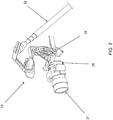
- the stabilization mechanism may comprise a variety of components such as a multi-axis gimbal (e.g., a three axis gimbal as shown in FIG. 2 ), a plurality of motors (e.g., five motors as shown in FIG. 3 ), a camera shelf, and at least one spring.
- the camera 21 may be mounted on an end of the monopod jib 22 (e.g., by way of the multi-axis gimbal 23).
- the camera may be attached to the main part of the monopod jib 22 via the multi-axis gimbal 23.
- a spring 24 may be located between the camera shelf 25 and a portion of the gimbal 23.
- the camera 21 may be attached to and securely rest on the camera shelf 25.
- the illustrated spring arrangement in FIG. 2 is only an example embodiment and other spring placement configurations may be utilized.
- the size and tension of the spring may depend on a bounce coefficient of the camera used.
- the bounce coefficient may refer to dimensional aspects of the camera such as mass, length, width, etc. For example, a camera weighing 5 pounds will require a different type of spring, having a different length, tension, size, and the like, than a camera weighing 10 pounds.
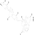
- FIG. 3 an example arrangement of a plurality of motors associated with the stabilization mechanism is illustrated.
- five motors i.e., Z 1 - Z 5
- fewer or additional motors may be used in different arrangements and embodiments.
- the camera's viewing angle e.g., pan/tilt/roll functions
- Z 1 , Z 3 , and Z 5 which offer three axes of rotation (e.g., that enable pointing of the camera left, right, up, and down).
- two additional motors are used in the stabilization mechanism to account for vertical displacement events (e.g., up and down displacement resulting from ambulatory movements of a jib operator). Additional motors may be used to account for displacement events in the horizontal direction (e.g., from shaking the jib left and right, etc.) as well as the directions in the z-plane (e.g., forward and backward). Each motor may not have a single role. Rather, a combination of motors may be used to perform a single function. For example, in the example, motors Z 4 and Z 5 are used in combination to account for the vertical displacement. However, it should be understood that other motors could be used alone, or in combination, to perform different functions.
- FIGs. 4A - 4E illustrate some example monopod jib movements and corresponding motor functions to compensate.
- FIG. 4A illustrates the camera 401 and motors 402A - 402E in a "normal" or no displacement event detected position.
- FIG. 4B the monopod jib 403 has been moved and rotated down. Accordingly, motor 402D works to compensate for or counteract the monopod 403 movement and maintain the camera 401 at the same position in space.
- FIG. 4C the monopod jib 403 has been pulled back. Accordingly, two motors 402B and 402D coordinate together to compensate for this movement.
- FIG. 4D the monopod jib 403 has been rotated and moved up. Accordingly, three motors 402A, 402B, and 402C work together to not only maintain the camera 401 at the same position in space and the same pointing direction.
- FIG. 4E illustrates that the motors may compensate for monopod jib 403 movement and adjust the pan and/or tilt of the camera 401.
- the monopod job 403 has been rotated and the operator wants to tilt the camera 401.
- the operator does not want the camera to vertically move in space.
- two motors 402A and 402C work together to not only maintain the camera 401 at the same position vertically, but to also move the camera to the desired angle.
- the motors will work together to perform the desired function while still maintaining the pointing direction or the camera in the same three-dimensional position in space.
- FIGs. 4A - 4E are merely illustrations. Other motor configurations are possible and contemplated. Additionally, motors other than those designated may work alone or in combination to perform the functions illustrated in the figures. The coordination of the motors is determined using the calculated adjustment value identified at 102.
- an embodiment may adjust a portion of the stabilization mechanism using at least one of the motors.
- a portion of the stabilization mechanism may refer to a single portion.
- the portion of the stabilization mechanism may be a portion that is most directly associated with the camera (e.g., the camera shelf 25).
- multiple portions of the stabilization mechanism e.g., the gimbal 23, the camera shelf 25, the spring 24, etc.).
- the portion(s) of the stabilization mechanism is adjusted by a determined amount associated with the displacement event.
- the determined amount may be an amount necessary for a camera to remain at its original position. For example, if a portion of the monopod jib is displaced vertically by two inches, responsive to determining the distance and direction of displacement (e.g., by analyzing the acceleration value) the plurality of motors may adjust a portion of the stabilization mechanism downwards by a corresponding amount to maintain the same pointing direction of the camera or maintain the camera at the same three-dimensional position it was at prior to the displacement event.
- the plurality of motors may work together to adjust the stabilization mechanism, or, alternatively, only one motor may be activated to adjust the stabilization mechanism.
- the system may measure the monopod jib and/or camera acceleration. This acceleration may then be sent through a low pass filter to filter any noise caused by the accelerometer or other sensor. The system may then process this acceleration value into an adjustment value to identify an amount or type of adjustment to be performed by one or more of the motors. Alternatively, or in addition to, the system may determine the pointing direction and/or position of the camera in three-dimensional space. The adjustment value may then be based upon the position rather than the acceleration value. Additionally, the system may measure the monopod jib and camera rotation/orientation and process pan/tilt commands to identify the motor commands needed to perform the desired function. Finally, the system may compensate for the weight of the camera, either using a spring or identifying a force on the system. To compensate for the weight, the system maintains one axis close to vertical to constrain the weight compensation to a single axis.
- the system integrates and coordinates these functions into motor commands that will perform the requested adjustment while maintaining the camera's pointing direction and/or the three-dimensional position in space.
- the system then sends the necessary signals to the motors to carry out the computed commands. Accordingly, the described system provides a system in which the stabilization can be performed by the gimbal, using components on the gimbal or other mechanical components of the system, without needing large pieces of equipment to perform the adjustments and provide compensation for the movements of an operator.
- an embodiment may determine an acceleration value associated with a displacement event and from that determination may identify the direction of displacement and predict the distance of displacement. Responsive to these calculations, an embodiment may then activate at least one of a plurality of motors to adjust a stabilization mechanism operatively coupled to a camera to maintain the camera at the same position it was at prior to the displacement event.
- Such techniques reduce instances of image distortion by maintaining the position of the camera at a consistent level throughout the shot.
- the system may include additional components, for example, a user interface element, microcontrollers, communication mechanisms, and the like.
- a microcontroller or processor may be used to provide instructions for moving the motors.
- a microcontroller or processor may receive the movement information, analyze the information, correlate the analyzed information to a motor movement, and provide instructions to the one or motors to move by the identified amount.
- the camera may communicate with a camera microcontroller, for example mounted on the gimbal.
- a central or main microcontroller may then coordinate the actions of the system.
- the microcontrollers and/or processors may be connected by a communication bus, e.g., via a standard RS 485 serial bus.
- Each motor may also have a corresponding microcontroller that control the moving components of the gimbal and another microcontroller for an IMU mounted on the monopod jib.
- the monopod jib microcontroller may be used for normal operation of the monopod jib.
- a storage device is not a signal and "non-transitory" includes all media except signal media.
- Program code embodied on a storage medium may be transmitted using any appropriate medium, including but not limited to wireless, wireline, optical fiber cable, RF, etc., or any suitable combination of the foregoing.
- Program code for carrying out operations may be written in any combination of one or more programming languages.
- the program code may execute entirely on a single device, partly on a single device, as a stand-alone software package, partly on single device and partly on another device, or entirely on the other device.
- the devices or components referred to herein communicate by a connection facilitated through network, e.g., a local area network (LAN) or a wide area network (WAN), or the connection may be made through other devices, through wireless connections, e.g., near-field communication, or through a hard wire connection, such as over a USB connection or bus communications as described herein.
- network e.g., a local area network (LAN) or a wide area network (WAN)
- LAN local area network
- WAN wide area network
- wireless connections e.g., near-field communication
- a hard wire connection such as over a USB connection or bus communications as described herein.
- Example embodiments are described herein with reference to the figures, which illustrate example methods, devices and products according to various example embodiments. It will be understood that the actions and functionality may be implemented at least in part by program instructions. These program instructions may be provided to a processor of a device, a special purpose information handling device, or other programmable data processing device to produce a machine, such that the instructions, which execute via a processor of the device implement the functions/acts specified.
Landscapes
- Engineering & Computer Science (AREA)
- General Engineering & Computer Science (AREA)
- Mechanical Engineering (AREA)
- Robotics (AREA)
- Physics & Mathematics (AREA)
- General Physics & Mathematics (AREA)
- Health & Medical Sciences (AREA)
- General Health & Medical Sciences (AREA)
- Orthopedic Medicine & Surgery (AREA)
- Studio Devices (AREA)
- Accessories Of Cameras (AREA)
Abstract
Description
- Monopod jibs (a monopole, pole, boom, stick, handle, or other device on which something can be attached at the end) are used with attachments that allow for the attachment of a pointer (e.g., laser pointer, camera, directional microphone, projector, light, etc.). An operator may then use the monopod jib with attached pointer to perform particular actions, for example, a monopod jib equipped with a camera may be used to capture certain shots that require the camera to be extended outward from a camera operator. Certain monopod jibs are equipped with a gimbal, i.e., an arrangement that acts to facilitate or control movement of the pointer mounted on the monopole jib. For example, a gimbal may be used to balance or counterbalance a pointer, buffering it from motion. Additionally, certain monopod jibs are provided with a multi-axis gimbal, which may be motorized, e.g., one or more motors may be provided to actively control movement of the gimbal components, and thus the pointer.
- In summary, one aspect provides a method, comprising: detecting, using at least one sensor, a displacement event associated with a monopod jib, wherein the displacement event moves a portion of the monopod jib from a first position to a second position; calculating, using a processor, an adjustment value for at least one of a plurality of motors of a stabilization mechanism operatively coupled to the monopod jib, wherein the calculated adjustment value identifies a motor movement to counteract the displacement event; activating the at least one of a plurality of motors corresponding to the calculated adjustment value; and adjusting, using the activated at least one of the plurality of motors, at least one portion of the stabilization mechanism using the calculated adjustment value.
- Another aspect provides an apparatus, comprising: a monopod jib; at least one sensor; a plurality of motors; a processor; a memory device that stores instructions executable by the processor to: detect, using the at least one sensor, a displacement event associated with a monopod jib, wherein the displacement event moves a portion of the monopod jib from a first position to a second position; calculate, using the processor, an adjustment value for at least one of a plurality of motors of a stabilization mechanism operatively coupled to the monopod jib, wherein the calculated adjustment value identifies a motor movement to counteract the displacement event; activate the at least one of a plurality of motors corresponding to the calculated adjustment value; and adjust, using the activated at least one of the plurality of motors, at least one portion of the stabilization mechanism using the calculated adjustment value.
- A further aspect provides a product, comprising: a storage device that stores code, the code being executable by a processor and comprising: code that detects, using at least one sensor, a displacement event associated with a monopod jib, wherein the displacement event moves a portion of the monopod jib from a first position to a second position; code that calculates an adjustment value for at least one of a plurality of motors of a stabilization mechanism operatively coupled to the monopod jib, wherein the calculated adjustment value identifies a motor movement to counteract the displacement event; code that activates the at least one of a plurality of motors corresponding to the calculated adjustment value; and code that adjusts, using the activated at least one of the plurality of motors, at least one portion of the stabilization mechanism using the calculated adjustment value.
- The foregoing is a summary and thus may contain simplifications, generalizations, and omissions of detail; consequently, those skilled in the art will appreciate that the summary is illustrative only and is not intended to be in any way limiting.
- For a better understanding of the embodiments, together with other and further features and advantages thereof, reference is made to the following description, taken in conjunction with the accompanying drawings. The scope of the embodiments will be pointed out in the appended claims.
-
-
FIG. 1 illustrates an example method of adjusting a portion of a stabilization mechanism based on determined acceleration data according to an embodiment. -
FIG. 2 illustrates an example configuration of a camera operatively coupled to a stabilization mechanism. -
FIG. 3 illustrates an arrangement of motors associated with the stabilization mechanism. -
FIGs. 4A - 4E illustrate arrangements of motors associated with the stabilization mechanism in response to movements of the monopod jib. - It will be readily understood that the components of the embodiments, as generally described and illustrated in the figures herein, may be arranged and designed in a wide variety of different configurations in addition to the described example embodiments. Thus, the following more detailed description of the example embodiments, as represented in the figures, is not intended to limit the scope of the embodiments, as claimed, but is merely representative of example embodiments.
- Reference throughout this specification to "one embodiment" or "an embodiment" (or the like) means that a particular feature, structure, or characteristic described in connection with the embodiment is included in at least one embodiment. Thus, appearances of the phrases "in one embodiment" or "in an embodiment" or the like in various places throughout this specification are not necessarily all referring to the same embodiment.
- Furthermore, the described features, structures, or characteristics may be combined in any suitable manner in one or more embodiments. In the following description, numerous specific details are provided to give a thorough understanding of embodiments. One skilled in the relevant art will recognize, however, that the various embodiments can be practiced without one or more of the specific details, or with other methods, components, materials, et cetera. In other instances, well-known structures, materials, or operations are not shown or described in detail to avoid obfuscation. The following description is intended only by way of example, and simply illustrates certain example embodiments.
- Monopod jibs equipped with a camera are frequently used in the film and television industry to capture various types of shots. The term monopod jib will be used herein throughout to refer to handle assembly only. The term monopod jib includes any device or assembly which can be used for mounting a device at a position on the jib or to extend the reach of an operator. For example, the term monopod jib may include a handle, stick, monopole, pole, boom, and the like, and may or may not include additional components, for example, electronics, mechanical components, extensions, or other components. A monopod jib can then be equipped with an attachment mechanism that allows the attachment of a pointer at a position on the jib. A pointer may include any device that may be mounted on a jib and whose direction and rotation can be controlled by the jib. For example, the term pointer may refer to a camera, laser pointer, light, microphone, projector, and the like. For ease of readability, the following discussion will focus on a monopod jib with an attached camera. However, this is not intended to limit the scope of this application to only a jib with a camera.
- Monopod jib assemblies with attached cameras allow an operator to follow (e.g., by walking with the jib) a moving scene, attain different camera angles of the same stationary scene, etc. Some monopod jibs include a gimbal. The gimbal provides a mechanism to rotate and move the pointer or the camera attached to the end of the monopod jib. However, although a jib with a gimbal is able to fix a camera so that it constantly points in a desired direction, the ambulatory movement of the operator may distort the recorded image. For example, when a recording of a scene that was filmed with a moving camera is played back, the up and down walking motion generated by the operator may be reflected in the recording. More particularly, the foreground may shift in relation to the background of the image, thereby distorting the scene and affecting the quality of the shot.
- Conventionally, in order to stabilize a camera and prevent operator movement from affecting the shot, operators have utilized a Steadicam®, or other like devices. The Steadicam® consists of a large body harness strapped to an operator as well as a jointed mechanism that "absorbs" the weight of the camera. This design configuration allows the camera to effectively float in front of the operator, remaining substantially still regardless of user movement. A primary reason why this configuration works is because many of the cameras used in filming have a great deal of mass which relates to inertia, so the camera does not want to move. Therefore, even if an operator moves, the camera itself moves very slowly and all of the disturbances generated from the ambulatory movement of the operator are absorbed.
- However, these conventional methods of camera stabilization are unable to be directly applied to cameras attached to monopod jibs or lightweight cameras. The problem with the application of the conventional approach is that cameras associated with the Steadicam® configuration are able to leverage their heavy mass to smooth out the picture. However, when using a monopod jib, heavy cameras simply cannot be placed far out on the jib because an operator would be unable to effectively hold and carry the jib. Therefore, lighter cameras must be utilized.
- Accordingly, an embodiment provides a system including a stabilization mechanism. In one embodiment, the stabilization mechanism may be used for maintaining the pointing direction of a camera, for example, for maintaining the pointing direction of a camera attached to a monopod jib. In an embodiment, a displacement event (e.g., a movement of the jib, a movement of the gimbal, etc.), for example, associated with ambulatory movement of an operator, and the like, may be detected. In one embodiment the displacement event may be detected using one or more sensors disposed on the jib and/or other mechanical component of the system (e.g., gimbal, camera, motor, etc.).
- Subsequent to the detection, an embodiment may calculate an adjustment value for at least one of the plurality of motors of a stabilization mechanism operatively coupled to the monopod jib. The adjustment value may identify a desired motor movement to counteract the displacement event. The desired motor movement may include a movement of one or more of the motors that counteracts the displacement event (e.g., the motors move in a manner which results in a particular point on the jib or other mechanical component of the system remaining at a constant point). In other words, the movement of the motors results in a particular point on the jib or other mechanical component not moving in response to the displacement event.
- In one embodiment the adjustment value may identify a desired deflection and desired joint angle to counteract the displacement event. The adjustment value may be based upon a determined amount of the movement associated with the displacement event, for example, by determining, using an accelerometer, a value of acceleration associated with the displacement event. In one embodiment, the adjustment value may be based upon a determined pointing direction or position of the camera or pointer in three-dimensional space, which may be detected using position sensors or other sensors disposed on the jib or other mechanical component. The adjustment value may then be based upon maintaining the pointing direction of the camera and/or maintaining the camera at the same location in the three-dimensional space.
- An embodiment may include a plurality of motors, e.g., five as used in the non-limiting examples illustrated, which control movement of the stabilization mechanism in coordination with movements of the monopod jib by the operator. The examples as described herein use five motors. However, a different number of motors may be used, for example, three, four, and the like. Responsive to the calculation, an embodiment may activate at least one of the motors to adjust a portion of the stabilization mechanism, for example, to maintain the camera at a consistent position (e.g., a consistent height, a fixed position in three-dimensional space, the pointing direction, etc.). Such a method reduces instances of image distortion by maintaining the height of the camera at a consistent level throughout the shot.
- The illustrated example embodiments will be best understood by reference to the figures. The following description is intended only by way of example, and simply illustrates certain example embodiments.
- Monopod jibs (a monopole or pole or boom) are used with attachments that allow for the attachment of a pointer (e.g., laser pointer, camera, directional microphone, projector, light, etc.). An operator may then use the monopod jib with attached pointer to perform particular actions, for example, a monopod jib equipped with a camera may be used to capture certain shots that require the camera to be extended outward from a camera operator. Examples of monopod jib architecture and design may be found in co-pending U.S. Patent Application Serial No.
15/429,666 - Referring now to
FIG. 1 , an embodiment may adjust a portion of a stabilization mechanism, for example, to maintain a camera attached to a monopod jib at a consistent pointing direction. At 101, an embodiment may detect a displacement event associated with a camera operatively coupled to a monopod jib. In an embodiment, the displacement event may be any event or force that may change the position of the camera, or component coupled to the camera, from an original position in space. For example, the displacement event may originate from ambulatory movements of a jib operator, strong gusts of wind that shake the jib, other forces affecting the movement of the jib, and the like. In an embodiment, the displacement event may be associated with a displacement of at least a portion of the monopod jib in any three-dimensional direction in space (e.g., up, down left, right, forward, backward, etc.). A displacement event is not necessarily a single event, for example, a movement up or down, rather, a displacement event may be a continuously continuing event, for example, a camera operator moving throughout the day. In other words, a displacement event may refer to a single event or may refer to a series of events or continuous events. - In an embodiment, the detecting may be done by at least one movement measuring sensor (e.g., an accelerometer, position sensors, a combination of sensors, another movement measuring device, etc.). For ease of readability, the movement measuring sensor used as an example throughout will be one or more accelerometers. However, this designation is not intended to be limiting and other movement measuring sensors may be used. In an embodiment, the accelerometer may be operatively coupled to the camera, operatively coupled to a stabilization mechanism associated with the camera, or operatively coupled to any other place on the monopod jib capable of accurately measuring aspects related to an expected displacement of the camera. The systems and methods as described herein are intended to stabilize the camera and prevent any displacement of the camera. Accordingly, the system and methods as described herein identify an expected displacement of the camera, as if the stabilization mechanism were not included.
- The displacement event may also be detected using position sensors or other sensors for detecting the position of an object within a three-dimensional space and/or detecting the pointing direction of the object. The position sensors may determine the position of a portion of the monopod jib or other mechanical component of the system within the three-dimensional space. For example, the camera attached to the monopod jib may include a position sensor, distance sensor, optical sensor, or other sensor that can be used to determine the position of the camera within space or the pointing direction of the camera, for example, the distance from the camera to the ground, the distance from the camera to other objects in space, a type of positioning sensor or other sensor that can determine three-dimensional coordinates of the camera within space, sensors for detecting the angle of the camera, and the like.
- In response to the displacement event, an embodiment may calculate an adjustment value for at least one of a plurality of motors of a stabilization mechanism operatively coupled to the monopod jib. The stabilization mechanism and motors will be described in more detail below. The calculated adjustment value may identify an amount of adjustment or movement for one or more of the motors that will counteract the displacement event. As an example, if a camera is attached to the monopod jib, the adjustment value may identify a value or amount for movement of the motors in order to maintain the pointing direction of the camera or maintain the camera at a three-dimensional position in space. In one embodiment, the calculated adjustment value may identify a desired deflection and desired joint angle that will counteract the displacement event.
- To calculate the desired deflection and desired joint angle a vertical stabilization joint may be pictured as follows:The vertical stabilization joint may be represented by:


- x base: position of the portion of the monopod jib in 3-dimensional space
- x cam: position of the camera in 3-dimensional space
- Δx: deflection between the portion of the monopod jib and the camera
- ẋ base: velocity of the portion of the monopod jib in 3-dimensional space
- ẋ cam: velocity of the camera in 3-dimensional space
- Δẋ: relative velocity between the portion of the monopod jib and the camera
- ẍ cam: acceleration of the camera in 3-dimensional space
- s: Laplace operator
- a[n]: newest acceleration value
- θd [n]: newest desired joint angle value
- Δxd [n]: newest desired deflection value
- Δẋd [n]: newest desired derivative of deflection value
- Δẍd [n]: newest desired 2nd derivative of deflection value
- Δxd [n - 1]: previous desired deflection value
- Δẋd [n - 1]: previous desired derivative of deflection value
- ξ: desired damping ratio of filter
- ωn : desired natural frequency of filter
- r: joint effective radius
- In one embodiment, the adjustment value may be based upon an acceleration value associated with the displacement event. For example, an accelerometer may measure the amount and direction of acceleration associated with the displacement event. The system may then use this acceleration value to determine the adjustment value to counteract the displacement event. In an embodiment, the acceleration value may relate to the acceleration of a portion of the monopod jib moving from a first position (e.g., an original position) to a second position (e.g., a displaced position). In an embodiment, the portion of the monopod jib may be any portion that may provide an accurate reflection of the acceleration the portion of the jib or camera attached to the jib may experience.
- The system may only include a single accelerometer capable of measuring acceleration in a single direction. However, measurement of acceleration in more than one direction is desirable. Therefore, if the accelerometer only measures acceleration in a single direction, the system may include more than one accelerometer to capture acceleration in a different direction. Alternatively, some accelerometers measure acceleration in more than one direction, for example, the accelerometer may measure acceleration on one, two, or three axes. The three-directional rate measurement capabilities of the accelerometer allow acceleration to be measured in any direction. In an embodiment, the acceleration value may be used to determine additional information about the displacement event such as the direction of displacement and the distance of displacement.
- To determine a displacement direction, an embodiment may compare the acceleration value to the numerical value of the force of gravity at the Earth's surface (i.e., 1g or 9.8 m/s2). For example, for an object at rest, the accelerometer will measure exactly 1g of acceleration. If an object is pulled upwards an accelerometer will measure greater than 1g of acceleration. If an object is pulled downwards an accelerometer will measure less than 1g of acceleration. An embodiment may therefore determine a value for an acceleration value associated with a displacement event and compare that value to 1g to determine a displacement direction, for example, a value less than 1g indicates the displacement direction is down, a value greater than 1g indicates the displacement direction is up, and the like. In an embodiment, an accelerometer may be calibrated to detect displacement in any direction (up, down, left, right, etc.).
- To determine a displacement distance, an embodiment may analyze the acceleration value to predict a distance a portion of the monopod jib may have been displaced. For example, a portion of the monopod jib may have been vertically moved two inches from an initial position as a result of ambulatory movement of an operator. In an embodiment, the prediction may be done by methods known to those having ordinary skill in the art (e.g., by counting the number of clock cycles, etc.). For example, the system may detect an acceleration or movement and may count the number of clock cycles until the acceleration or movement subsides. Then, by knowing the number of clock cycles and the value for the acceleration, the system can solve the acceleration formula to determine the distance traveled during the displacement event.
- In one embodiment, calculation of an adjustment value may be based upon the pointing direction or three-dimensional position of the camera or pointer in space. The adjustment value may be calculated or computed to maintain the pointing direction or three-dimensional position of the camera. The adjustment value may then be calculated based upon a value associated with the displacement event, the pointing direction of the pointer, and a compensation value of at least one spring of the stabilization mechanism, as discussed in more detail below. In other words, calculation of the adjustment value may include coordinating with the gimbal, angle, and/or pointing stabilization. In other words, to accurately compensate or counteract the displacement event, the system may identify not only the three-dimensional position of the camera and/or acceleration value, but the system may also identify where the camera is currently pointed and/or the angle at which the camera is pointed. Such information may be derived from sensors other than those already discussed, sensors as already discussed, or information received from another component of the system, for example, position information from the gimbal. The gimbal may also act as the stabilization mechanism, as discussed in more detail below. The stabilization may then be completed using the coordinated information and the weight compensation, as explained in more detail below.
- If an adjustment value cannot be calculated at 102, the system may perform no action at 103. Alternatively, the calculation may still occur, but the system may determine that the adjustment value should be zero. However, if an adjustment value can be calculated at 102, the system may activate the at least one motor corresponding to the calculated adjustment value. For example, if the adjustment value indicates that two motors should be adjusted to fulfill the adjustment value, these motors may be activated. In an embodiment, the camera may be operatively coupled to the stabilization mechanism which may itself be operatively coupled to an end of the monopod jib. The stabilization mechanism may comprise a variety of components such as a multi-axis gimbal (e.g., a three axis gimbal as shown in
FIG. 2 ), a plurality of motors (e.g., five motors as shown inFIG. 3 ), a camera shelf, and at least one spring. - Referring now to
FIG. 2 , thecamera 21 may be mounted on an end of the monopod jib 22 (e.g., by way of the multi-axis gimbal 23). The camera may be attached to the main part of themonopod jib 22 via themulti-axis gimbal 23. In an embodiment, aspring 24 may be located between thecamera shelf 25 and a portion of thegimbal 23. Thecamera 21 may be attached to and securely rest on thecamera shelf 25. Such a configuration alleviates the weight of the camera off of the motors. The illustrated spring arrangement inFIG. 2 is only an example embodiment and other spring placement configurations may be utilized. In an embodiment, the size and tension of the spring may depend on a bounce coefficient of the camera used. The bounce coefficient may refer to dimensional aspects of the camera such as mass, length, width, etc. For example, a camera weighing 5 pounds will require a different type of spring, having a different length, tension, size, and the like, than a camera weighing 10 pounds. - Referring now to
FIG. 3 , an example arrangement of a plurality of motors associated with the stabilization mechanism is illustrated. InFIG. 3 , five motors (i.e., Z1 - Z5) are illustrated; however, fewer or additional motors may be used in different arrangements and embodiments. In an embodiment, the camera's viewing angle (e.g., pan/tilt/roll functions) is controlled by three motors Z1, Z3, and Z5, which offer three axes of rotation (e.g., that enable pointing of the camera left, right, up, and down). In an embodiment, two additional motors, e.g., Z4 and Z5, are used in the stabilization mechanism to account for vertical displacement events (e.g., up and down displacement resulting from ambulatory movements of a jib operator). Additional motors may be used to account for displacement events in the horizontal direction (e.g., from shaking the jib left and right, etc.) as well as the directions in the z-plane (e.g., forward and backward). Each motor may not have a single role. Rather, a combination of motors may be used to perform a single function. For example, in the example, motors Z4 and Z5 are used in combination to account for the vertical displacement. However, it should be understood that other motors could be used alone, or in combination, to perform different functions. - For example,
FIGs. 4A - 4E illustrate some example monopod jib movements and corresponding motor functions to compensate.FIG. 4A illustrates thecamera 401 andmotors 402A - 402E in a "normal" or no displacement event detected position. InFIG. 4B , themonopod jib 403 has been moved and rotated down. Accordingly,motor 402D works to compensate for or counteract themonopod 403 movement and maintain thecamera 401 at the same position in space. InFIG. 4C , themonopod jib 403 has been pulled back. Accordingly, twomotors FIG. 4D , themonopod jib 403 has been rotated and moved up. Accordingly, threemotors camera 401 at the same position in space and the same pointing direction. -
FIG. 4E illustrates that the motors may compensate formonopod jib 403 movement and adjust the pan and/or tilt of thecamera 401. InFIG. 4E , themonopod job 403 has been rotated and the operator wants to tilt thecamera 401. However, the operator does not want the camera to vertically move in space. Accordingly, twomotors camera 401 at the same position vertically, but to also move the camera to the desired angle. In other words, the motors will work together to perform the desired function while still maintaining the pointing direction or the camera in the same three-dimensional position in space. Other motors may be inserted to compensate or perform other functions, for example, an additional motor may be inserted to roll the camera and/or compensate for the movement of the gimbal from side-to-side.FIGs. 4A - 4E are merely illustrations. Other motor configurations are possible and contemplated. Additionally, motors other than those designated may work alone or in combination to perform the functions illustrated in the figures. The coordination of the motors is determined using the calculated adjustment value identified at 102. - At 105, an embodiment may adjust a portion of the stabilization mechanism using at least one of the motors. In an embodiment, a portion of the stabilization mechanism may refer to a single portion. For example, the portion of the stabilization mechanism may be a portion that is most directly associated with the camera (e.g., the camera shelf 25). In another embodiment, multiple portions of the stabilization mechanism (e.g., the
gimbal 23, thecamera shelf 25, thespring 24, etc.). - In an embodiment, the portion(s) of the stabilization mechanism is adjusted by a determined amount associated with the displacement event. The determined amount may be an amount necessary for a camera to remain at its original position. For example, if a portion of the monopod jib is displaced vertically by two inches, responsive to determining the distance and direction of displacement (e.g., by analyzing the acceleration value) the plurality of motors may adjust a portion of the stabilization mechanism downwards by a corresponding amount to maintain the same pointing direction of the camera or maintain the camera at the same three-dimensional position it was at prior to the displacement event. In an embodiment, the plurality of motors may work together to adjust the stabilization mechanism, or, alternatively, only one motor may be activated to adjust the stabilization mechanism.
- As discussed in detail above, the system may measure the monopod jib and/or camera acceleration. This acceleration may then be sent through a low pass filter to filter any noise caused by the accelerometer or other sensor. The system may then process this acceleration value into an adjustment value to identify an amount or type of adjustment to be performed by one or more of the motors. Alternatively, or in addition to, the system may determine the pointing direction and/or position of the camera in three-dimensional space. The adjustment value may then be based upon the position rather than the acceleration value. Additionally, the system may measure the monopod jib and camera rotation/orientation and process pan/tilt commands to identify the motor commands needed to perform the desired function. Finally, the system may compensate for the weight of the camera, either using a spring or identifying a force on the system. To compensate for the weight, the system maintains one axis close to vertical to constrain the weight compensation to a single axis.
- Once the system has the adjustment value, the motor commands for moving the camera, and the weight compensation, the system integrates and coordinates these functions into motor commands that will perform the requested adjustment while maintaining the camera's pointing direction and/or the three-dimensional position in space. The system then sends the necessary signals to the motors to carry out the computed commands. Accordingly, the described system provides a system in which the stabilization can be performed by the gimbal, using components on the gimbal or other mechanical components of the system, without needing large pieces of equipment to perform the adjustments and provide compensation for the movements of an operator.
- The various embodiments described herein thus represent a technical improvement to adjusting a stabilization mechanism of a monopod jib to maintain a camera at a particular position in space. Using the techniques described herein, an embodiment may determine an acceleration value associated with a displacement event and from that determination may identify the direction of displacement and predict the distance of displacement. Responsive to these calculations, an embodiment may then activate at least one of a plurality of motors to adjust a stabilization mechanism operatively coupled to a camera to maintain the camera at the same position it was at prior to the displacement event. Such techniques reduce instances of image distortion by maintaining the position of the camera at a consistent level throughout the shot.
- The system may include additional components, for example, a user interface element, microcontrollers, communication mechanisms, and the like. For example, a microcontroller or processor may be used to provide instructions for moving the motors. As an example, a microcontroller or processor may receive the movement information, analyze the information, correlate the analyzed information to a motor movement, and provide instructions to the one or motors to move by the identified amount. As another example, the camera may communicate with a camera microcontroller, for example mounted on the gimbal. A central or main microcontroller may then coordinate the actions of the system. The microcontrollers and/or processors may be connected by a communication bus, e.g., via a standard RS 485 serial bus. Each motor may also have a corresponding microcontroller that control the moving components of the gimbal and another microcontroller for an IMU mounted on the monopod jib. The monopod jib microcontroller may be used for normal operation of the monopod jib.
- It should be noted that the various functions described herein may be implemented using instructions stored on a device readable storage medium such as a non-signal storage device that are executed by a processor. In the context of this document, a storage device is not a signal and "non-transitory" includes all media except signal media.
- Program code embodied on a storage medium may be transmitted using any appropriate medium, including but not limited to wireless, wireline, optical fiber cable, RF, etc., or any suitable combination of the foregoing.
- Program code for carrying out operations may be written in any combination of one or more programming languages. The program code may execute entirely on a single device, partly on a single device, as a stand-alone software package, partly on single device and partly on another device, or entirely on the other device.
- In some cases, the devices or components referred to herein communicate by a connection facilitated through network, e.g., a local area network (LAN) or a wide area network (WAN), or the connection may be made through other devices, through wireless connections, e.g., near-field communication, or through a hard wire connection, such as over a USB connection or bus communications as described herein.
- Example embodiments are described herein with reference to the figures, which illustrate example methods, devices and products according to various example embodiments. It will be understood that the actions and functionality may be implemented at least in part by program instructions. These program instructions may be provided to a processor of a device, a special purpose information handling device, or other programmable data processing device to produce a machine, such that the instructions, which execute via a processor of the device implement the functions/acts specified.
- It is worth noting that while specific figures are used, and particular examples have been illustrated, these are non-limiting examples. In certain contexts, two or more elements may be combined, an element may be split into two or more elements, or certain elements may be re-ordered or re-organized as appropriate, as the explicit illustrated examples are used only for descriptive purposes and are not to be construed as limiting.
- This disclosure has been presented for purposes of illustration and description but is not intended to be exhaustive or limiting. Many modifications and variations will be apparent to those of ordinary skill in the art. The example embodiments were chosen and described in order to explain principles and practical application, and to enable others of ordinary skill in the art to understand the disclosure for various embodiments with various modifications as are suited to the particular use contemplated.


Claims (15)
- A method, comprising:detecting, using at least one sensor, a displacement event associated with a monopod jib (22), wherein the displacement event moves a portion of the monopod jib from a first position to a second position;calculating, using a processor, an adjustment value for at least one of a plurality of motors (Z1-Z5; 402A-402E) of a stabilization mechanism operatively coupled to the monopod jib, wherein the calculated adjustment value identifies a motor movement to counteract the displacement event;activating the at least one of a plurality of motors (Z1-Z5; 402A-402E)corresponding to the calculated adjustment value; andadjusting, using the activated at least one of the plurality of motors (Z1-Z5; 402A-402E), at least one portion of the stabilization mechanism using the calculated adjustment value.
- The method of claim 1, wherein the displacement event comprises movement associated with an ambulatory movement of a user.
- The method of claim 1, further comprising measuring, using an accelerometer, an acceleration value associated with the displacement event.
- The method of claim 3, wherein the determining the acceleration value comprises determining the acceleration associated with the portion of the monopod jib (22) moving from the first position to the second position.
- The method of claim 3, further comprising determining a direction of the displacement event by comparing the acceleration value to a predefined unit associated with gravitational acceleration.
- The method of claim 1, further comprising determining a pointing direction of a pointer operatively coupled to the monopod jib (22), wherein the adjusting comprises adjusting the at least one portion of the stabilization mechanism by a calculated adjustment value to maintain the pointing direction of the pointer.
- The method of claim 1, wherein the stabilization mechanism comprises at least one spring (24).
- An apparatus, comprising:a monopod jib (22);at least one sensor;a plurality of motors (Z1-Z5; 402A-402E);a processor;a memory device that stores instructions executable by the processor to:detect, using the at least one sensor, a displacement event associated with a monopod jib (22), wherein the displacement event moves a portion of the monopod jib from a first position to a second position;calculate, using the processor, an adjustment value for at least one of a plurality of motors (Z1-Z5; 402A-402E) of a stabilization mechanism operatively coupled to the monopod jib, wherein the calculated adjustment value identifies a motor movement to counteract the displacement event;activate the at least one of a plurality of motors (Z1-Z5; 402A-402E) corresponding to the calculated adjustment value; andadjust, using the activated at least one of the plurality of motors (Z1-Z5; 402A-402E), at least one portion of the stabilization mechanism using the calculated adjustment value.
- The apparatus of claim 8, wherein the instructions executable by the processor further comprise instructions to measure, using an accelerometer, an acceleration value associated with the displacement event.
- The apparatus of claim 9, wherein the instructions executable by the processor to determine the acceleration value comprises instructions to determine the acceleration associated with the portion of the monopod jib (22) moving from the first position to the second position.
- The apparatus of claim 9, wherein the instructions executable by the processor further comprise instructions to determine, using the acceleration value, a distance between the first position and the second position.
- The apparatus of claim 8, wherein the instructions are further executable by the processor to determine a pointing direction of a pointer operatively coupled to the monopod jib (22) and wherein the instructions executable by the processor to adjust comprise instructions executable to adjust the at least one portion of the stabilization mechanism by a calculated adjustment value to maintain the pointing direction of the pointer.
- The apparatus of claim 12, wherein the adjustment value is calculated based upon a value associated with the displacement event, the pointing direction of the pointer, and a compensation value of at least one spring of the stabilization mechanism.
- The apparatus of claim 8, wherein the stabilization mechanism comprises at least one spring and wherein the at least one spring (24) comprises a size and a tension associated with a bounce coefficient of the monopod jib (22).
- A product, comprising:
a storage device that stores code, the code being executable by a processor and comprising:code that detects, using at least one sensor, a displacement event associated with a monopod jib (22), wherein the displacement event moves a portion of the monopod jib from a first position to a second position;code that calculates an adjustment value for at least one of a plurality of motors (Z1-Z5; 402A-402E) of a stabilization mechanism operatively coupled to the monopod jib (22), wherein the calculated adjustment value identifies a motor movement to counteract the displacement event;code that activates the at least one of a plurality of motors (Z1-Z5; 402A-402E) corresponding to the calculated adjustment value; andcode that adjusts, using the activated at least one of the plurality of motors (Z1-Z5; 402A-402E), at least one portion of the stabilization mechanism using the calculated adjustment value.
Applications Claiming Priority (1)
| Application Number | Priority Date | Filing Date | Title |
|---|---|---|---|
| US15/639,362 US10583556B2 (en) | 2017-06-30 | 2017-06-30 | Motion stabilization on a motorized monopod jib |
Publications (2)
| Publication Number | Publication Date |
|---|---|
| EP3421861A1 true EP3421861A1 (en) | 2019-01-02 |
| EP3421861B1 EP3421861B1 (en) | 2020-08-26 |
Family
ID=62837569
Family Applications (1)
| Application Number | Title | Priority Date | Filing Date |
|---|---|---|---|
| EP18178234.3A Active EP3421861B1 (en) | 2017-06-30 | 2018-06-18 | Motion stabilization on a motorized monopod jib |
Country Status (3)
| Country | Link |
|---|---|
| US (1) | US10583556B2 (en) |
| EP (1) | EP3421861B1 (en) |
| CN (1) | CN109202892B (en) |
Families Citing this family (6)
| Publication number | Priority date | Publication date | Assignee | Title |
|---|---|---|---|---|
| FR3107754B1 (en) * | 2020-02-27 | 2022-03-18 | Xyzed | Motorized moving head for video projector |
| US11637959B2 (en) * | 2020-04-09 | 2023-04-25 | Marbl Llc | Orbital camera system |
| US11608932B2 (en) * | 2020-06-24 | 2023-03-21 | Thomas A Drummond | Water-meter extension pole |
| GB202014590D0 (en) | 2020-09-16 | 2020-10-28 | Stanley Works Israel | Laser tool and system |
| US12302890B2 (en) * | 2022-02-04 | 2025-05-20 | Justin Huang | Reusable non-lethal insect trap |
| CN115949854B (en) * | 2022-12-30 | 2024-01-09 | 深圳市浩瀚卓越科技有限公司 | Control method and device of cradle head, computer equipment and storage medium |
Citations (3)
| Publication number | Priority date | Publication date | Assignee | Title |
|---|---|---|---|---|
| US20160246162A1 (en) * | 2015-02-20 | 2016-08-25 | Disney Enterprises, Inc. | Motorized monopod jib for cameras |
| WO2016190994A1 (en) * | 2015-05-27 | 2016-12-01 | Gopro, Inc. | Camera system using stabilizing gimbal |
| US20170159875A1 (en) * | 2011-11-02 | 2017-06-08 | Steven D. Wagner | Actively stabilized payload support apparatus and methods |
Family Cites Families (52)
| Publication number | Priority date | Publication date | Assignee | Title |
|---|---|---|---|---|
| US4017168A (en) | 1974-09-16 | 1977-04-12 | Brown Garrett W | Equipment for use with hand held motion picture cameras |
| US4946272A (en) | 1988-09-22 | 1990-08-07 | Brown Garrett W | Stabilized equipment support, primarily for use with light-weight cameras |
| US5065249A (en) | 1988-09-26 | 1991-11-12 | Vicon Industries, Inc. | Portable video camera/monitor support |
| US5963749A (en) | 1998-02-09 | 1999-10-05 | Nicholson; Lynn | Self-leveling invertible camera stabilizer |
| JP2003500772A (en) | 1999-05-28 | 2003-01-07 | グロバー、デイビッド、イー | Self-leveling self-correcting automatic stabilizer |
| JP2003219225A (en) | 2002-01-25 | 2003-07-31 | Nippon Micro Systems Kk | Device for monitoring moving object image |
| US6808324B2 (en) | 2003-03-12 | 2004-10-26 | Mckay Thomas L. | Image stabilization and balancing system |
| US20040223078A1 (en) * | 2003-05-09 | 2004-11-11 | Adam Zadok | Support for hand held video camera |
| US20050052531A1 (en) | 2003-09-04 | 2005-03-10 | Chapman/Leonard Studio Equipment | Stabilized camera platform system |
| US7209176B2 (en) | 2004-02-19 | 2007-04-24 | Chapman/Leonard Studio Equipment | Three-axis remote camera head |
| US7522213B2 (en) | 2004-04-16 | 2009-04-21 | Chapman/Leonard Studio Equipment | Shock and vibration isolator for a camera |
| US7241060B2 (en) | 2004-03-03 | 2007-07-10 | Jeffery Scott Mootz | Self leveling camera support apparatus |
| JP4492432B2 (en) | 2005-05-13 | 2010-06-30 | 株式会社デンソー | Manufacturing method of physical quantity sensor device |
| US20090003822A1 (en) | 2007-06-27 | 2009-01-01 | Frank Tyner | Hand-held photographic support system |
| US9156154B2 (en) | 2007-09-17 | 2015-10-13 | Garrett W. Brown | Gimbal assembly for tool support |
| FI123361B (en) * | 2007-10-01 | 2013-03-15 | Sandvik Mining & Constr Oy | Procedure and apparatus and computer program for adjusting the function of a hydraulic boom |
| CN102209934A (en) | 2008-11-14 | 2011-10-05 | 加勒特·W·布朗 | Extendable camera support and stabilization apparatus |
| US8506180B2 (en) | 2008-11-14 | 2013-08-13 | Garrett W. Brown | Extendable camera support and stabilization apparatus |
| US8322269B2 (en) * | 2009-02-06 | 2012-12-04 | Flex Force Enterprises LLC | Weapons stabilization and compensation system |
| JP2011137996A (en) | 2009-12-28 | 2011-07-14 | Canon Inc | Lens device |
| WO2012027549A1 (en) | 2010-08-26 | 2012-03-01 | Equipois, Inc. | Multi-arm gimbal system |
| WO2013067335A1 (en) * | 2011-11-02 | 2013-05-10 | Wagner Steven D | Actively stabilized payload support apparatus and methods |
| WO2013096766A2 (en) | 2011-12-21 | 2013-06-27 | Shachaf Catherine M | System for imaging lesions aligning tissue surfaces |
| CN202647109U (en) | 2012-06-04 | 2013-01-02 | 深圳市大疆创新科技有限公司 | Electric adjusting device, and holder and aircraft with same |
| US8534934B1 (en) | 2012-06-14 | 2013-09-17 | Peter L. Carney | Camera stabilization device and method of use |
| US9454064B2 (en) | 2014-02-04 | 2016-09-27 | Disney Enterprises, Inc. | Motorized monopod jib for cameras |
| CN103984193B (en) | 2014-03-14 | 2020-10-16 | 广州虹天航空科技有限公司 | Photographing apparatus stabilizer and control method thereof |
| EP3124850B1 (en) * | 2014-03-27 | 2021-01-27 | SZ DJI Osmo Technology Co., Ltd. | Cradle head |
| DK3139239T3 (en) * | 2014-04-30 | 2019-04-15 | Sz Dji Osmo Technology Co Ltd | Control unit, cradle head for use and cradle control method |
| CN203812021U (en) | 2014-04-30 | 2014-09-03 | 易浩 | Gyroscope handheld stabilizer |
| CN203811969U (en) | 2014-04-30 | 2014-09-03 | 易浩 | Micro single-board gyroscope handheld stabilizer |
| EP3770480A1 (en) * | 2014-06-27 | 2021-01-27 | SZ DJI Osmo Technology Co., Ltd. | Tripod head structure and gear adjustment mechanism thereof |
| WO2016015232A1 (en) | 2014-07-29 | 2016-02-04 | SZ DJI Technology Co., Ltd. | Systems and methods for payload stabilization |
| ES2564393B1 (en) | 2014-09-22 | 2016-12-28 | Jesús Ángel ALONSO PÉREZ | Telescopic handheld stabilizer for video / photo camera |
| CN104360690A (en) | 2014-11-05 | 2015-02-18 | 桂林飞宇电子科技有限公司 | Handheld triaxial head |
| CN204227000U (en) | 2014-11-10 | 2015-03-25 | 李强 | Self-shooting bar |
| US9835934B2 (en) | 2014-12-12 | 2017-12-05 | Chips Unlimited, Inc. | Systems and methods for mounting photographic equipment |
| CN204437648U (en) | 2015-01-23 | 2015-07-01 | 桂林飞宇电子科技有限公司 | A kind of hand-held three axle The Cloud Terraces using mobile phone to take |
| KR20150028277A (en) | 2015-02-12 | 2015-03-13 | 주식회사 삐삐클리닉 | Electric monopod for self-camera |
| CN104728573B (en) * | 2015-03-13 | 2018-05-15 | 杨子良 | Multifunctional photographic frame |
| US10208887B2 (en) * | 2015-04-13 | 2019-02-19 | Yuneec Technology Co., Limited | Gimbal handheld holder |
| US9243741B1 (en) | 2015-04-20 | 2016-01-26 | Intellectual Fortress, LLC | Telescoping monopod apparatus for holding photographic instrument |
| TWI582519B (en) | 2015-04-30 | 2017-05-11 | 鴻海精密工業股份有限公司 | Selfie |
| US9749522B2 (en) * | 2015-06-02 | 2017-08-29 | Alan Holmes | Tracking device for portable astrophotography of the night sky |
| DE202015007294U1 (en) * | 2015-10-20 | 2015-11-06 | Zhongshan Nikow Precision Industrial Co., Ltd. | Automatic Leg Tube Locking Device, Photography Tripod, Monopod and Prop |
| US9973665B2 (en) * | 2015-11-03 | 2018-05-15 | GE Lighting Solutions, LLC | System and method for sensor adjustment |
| CN205101801U (en) * | 2015-11-06 | 2016-03-23 | 深圳市道通智能航空技术有限公司 | Unmanned vehicles , image shooting device and cloud platform thereof |
| CN114435611B (en) * | 2016-01-26 | 2024-11-05 | 深圳市大疆创新科技有限公司 | Stabilization platform |
| EP3411620A4 (en) * | 2016-02-01 | 2019-01-23 | SZ DJI Technology Co., Ltd. | SYSTEMS AND METHODS FOR PAYLOAD STABILIZATION |
| US10547773B2 (en) | 2016-10-28 | 2020-01-28 | Disney Enterprises, Inc. | User interface aspects for a motorized monopod jib for cameras |
| KR20180060634A (en) * | 2016-11-29 | 2018-06-07 | 한화에어로스페이스 주식회사 | Dome type 3-axis gimbal |
| US10465840B2 (en) * | 2017-03-22 | 2019-11-05 | Gopro, Inc. | Calibration for image stabilization mechanism |
-
2017
- 2017-06-30 US US15/639,362 patent/US10583556B2/en active Active
-
2018
- 2018-06-18 EP EP18178234.3A patent/EP3421861B1/en active Active
- 2018-06-28 CN CN201810687784.8A patent/CN109202892B/en active Active
Patent Citations (3)
| Publication number | Priority date | Publication date | Assignee | Title |
|---|---|---|---|---|
| US20170159875A1 (en) * | 2011-11-02 | 2017-06-08 | Steven D. Wagner | Actively stabilized payload support apparatus and methods |
| US20160246162A1 (en) * | 2015-02-20 | 2016-08-25 | Disney Enterprises, Inc. | Motorized monopod jib for cameras |
| WO2016190994A1 (en) * | 2015-05-27 | 2016-12-01 | Gopro, Inc. | Camera system using stabilizing gimbal |
Also Published As
| Publication number | Publication date |
|---|---|
| CN109202892A (en) | 2019-01-15 |
| US20190001494A1 (en) | 2019-01-03 |
| CN109202892B (en) | 2023-08-22 |
| US10583556B2 (en) | 2020-03-10 |
| EP3421861B1 (en) | 2020-08-26 |
Similar Documents
| Publication | Publication Date | Title |
|---|---|---|
| EP3421861B1 (en) | Motion stabilization on a motorized monopod jib | |
| US9900511B2 (en) | Method, system, and device for controlling a stabilized camera remotely | |
| KR102198193B1 (en) | Auto-focusing apparatus by target of air photograph camera | |
| KR101551380B1 (en) | An air photograph renewal system reflecting change of geographic feature | |
| US10551724B2 (en) | Motorized monopod jib for cameras | |
| US20140267778A1 (en) | Apparatuses and methods for controlling a gimbal and other displacement systems | |
| KR20110030639A (en) | Motion Capture Pointers Using Data Fusion | |
| JP2002533640A (en) | Optical equipment mountings or mounting related enhancements | |
| CN203705964U (en) | Stable closed-loop control device of airborne 3-DOF pan-tilt | |
| CN103394199A (en) | Method for controlling rotary-wing drone to operate photography by on-board camera with minimisation of interfering movements | |
| WO2013158050A1 (en) | Stabilization control system for flying or stationary platforms | |
| US20080054158A1 (en) | Tracking a moving object from a camera on a moving platform | |
| KR102122755B1 (en) | Gimbal control method using screen touch | |
| WO2016020501A1 (en) | Apparatus and method for measuring a bending angle of a workpiece | |
| WO2018214005A1 (en) | Method for controlling agricultural unmanned aerial vehicle, flight controller, and agricultural unmanned airplane | |
| US20170068242A1 (en) | Remote control device, control system and method of controlling | |
| CN117597532A (en) | PTZ control method, device, PTZ and storage medium | |
| US20160368602A1 (en) | Camera drone systems and methods for maintaining captured real-time images vertical | |
| US20190130177A1 (en) | Posture control system | |
| CN113826377A (en) | Control method and device of holder, holder and movable platform | |
| CN114641746B (en) | Movable platform and control method and device thereof | |
| US12316967B2 (en) | Multi-axis camera stabilization system and operation method | |
| KR101548726B1 (en) | Flight recording system | |
| KR101763812B1 (en) | Monitoring system for loading | |
| EP0658797B1 (en) | Image movement correction of camera |
Legal Events
| Date | Code | Title | Description |
|---|---|---|---|
| PUAI | Public reference made under article 153(3) epc to a published international application that has entered the european phase |
Free format text: ORIGINAL CODE: 0009012 |
|
| STAA | Information on the status of an ep patent application or granted ep patent |
Free format text: STATUS: THE APPLICATION HAS BEEN PUBLISHED |
|
| AK | Designated contracting states |
Kind code of ref document: A1 Designated state(s): AL AT BE BG CH CY CZ DE DK EE ES FI FR GB GR HR HU IE IS IT LI LT LU LV MC MK MT NL NO PL PT RO RS SE SI SK SM TR |
|
| AX | Request for extension of the european patent |
Extension state: BA ME |
|
| STAA | Information on the status of an ep patent application or granted ep patent |
Free format text: STATUS: REQUEST FOR EXAMINATION WAS MADE |
|
| 17P | Request for examination filed |
Effective date: 20190701 |
|
| RBV | Designated contracting states (corrected) |
Designated state(s): AL AT BE BG CH CY CZ DE DK EE ES FI FR GB GR HR HU IE IS IT LI LT LU LV MC MK MT NL NO PL PT RO RS SE SI SK SM TR |
|
| GRAP | Despatch of communication of intention to grant a patent |
Free format text: ORIGINAL CODE: EPIDOSNIGR1 |
|
| STAA | Information on the status of an ep patent application or granted ep patent |
Free format text: STATUS: GRANT OF PATENT IS INTENDED |
|
| INTG | Intention to grant announced |
Effective date: 20200324 |
|
| GRAS | Grant fee paid |
Free format text: ORIGINAL CODE: EPIDOSNIGR3 |
|
| GRAA | (expected) grant |
Free format text: ORIGINAL CODE: 0009210 |
|
| STAA | Information on the status of an ep patent application or granted ep patent |
Free format text: STATUS: THE PATENT HAS BEEN GRANTED |
|
| AK | Designated contracting states |
Kind code of ref document: B1 Designated state(s): AL AT BE BG CH CY CZ DE DK EE ES FI FR GB GR HR HU IE IS IT LI LT LU LV MC MK MT NL NO PL PT RO RS SE SI SK SM TR |
|
| REG | Reference to a national code |
Ref country code: GB Ref legal event code: FG4D |
|
| REG | Reference to a national code |
Ref country code: CH Ref legal event code: EP |
|
| REG | Reference to a national code |
Ref country code: AT Ref legal event code: REF Ref document number: 1306715 Country of ref document: AT Kind code of ref document: T Effective date: 20200915 |
|
| REG | Reference to a national code |
Ref country code: IE Ref legal event code: FG4D |
|
| REG | Reference to a national code |
Ref country code: DE Ref legal event code: R096 Ref document number: 602018007221 Country of ref document: DE |
|
| REG | Reference to a national code |
Ref country code: LT Ref legal event code: MG4D |
|
| PG25 | Lapsed in a contracting state [announced via postgrant information from national office to epo] |
Ref country code: HR Free format text: LAPSE BECAUSE OF FAILURE TO SUBMIT A TRANSLATION OF THE DESCRIPTION OR TO PAY THE FEE WITHIN THE PRESCRIBED TIME-LIMIT Effective date: 20200826 Ref country code: BG Free format text: LAPSE BECAUSE OF FAILURE TO SUBMIT A TRANSLATION OF THE DESCRIPTION OR TO PAY THE FEE WITHIN THE PRESCRIBED TIME-LIMIT Effective date: 20201126 Ref country code: LT Free format text: LAPSE BECAUSE OF FAILURE TO SUBMIT A TRANSLATION OF THE DESCRIPTION OR TO PAY THE FEE WITHIN THE PRESCRIBED TIME-LIMIT Effective date: 20200826 Ref country code: PT Free format text: LAPSE BECAUSE OF FAILURE TO SUBMIT A TRANSLATION OF THE DESCRIPTION OR TO PAY THE FEE WITHIN THE PRESCRIBED TIME-LIMIT Effective date: 20201228 Ref country code: NO Free format text: LAPSE BECAUSE OF FAILURE TO SUBMIT A TRANSLATION OF THE DESCRIPTION OR TO PAY THE FEE WITHIN THE PRESCRIBED TIME-LIMIT Effective date: 20201126 Ref country code: SE Free format text: LAPSE BECAUSE OF FAILURE TO SUBMIT A TRANSLATION OF THE DESCRIPTION OR TO PAY THE FEE WITHIN THE PRESCRIBED TIME-LIMIT Effective date: 20200826 Ref country code: GR Free format text: LAPSE BECAUSE OF FAILURE TO SUBMIT A TRANSLATION OF THE DESCRIPTION OR TO PAY THE FEE WITHIN THE PRESCRIBED TIME-LIMIT Effective date: 20201127 Ref country code: FI Free format text: LAPSE BECAUSE OF FAILURE TO SUBMIT A TRANSLATION OF THE DESCRIPTION OR TO PAY THE FEE WITHIN THE PRESCRIBED TIME-LIMIT Effective date: 20200826 |
|
| REG | Reference to a national code |
Ref country code: NL Ref legal event code: MP Effective date: 20200826 |
|
| REG | Reference to a national code |
Ref country code: AT Ref legal event code: MK05 Ref document number: 1306715 Country of ref document: AT Kind code of ref document: T Effective date: 20200826 |
|
| PG25 | Lapsed in a contracting state [announced via postgrant information from national office to epo] |
Ref country code: NL Free format text: LAPSE BECAUSE OF FAILURE TO SUBMIT A TRANSLATION OF THE DESCRIPTION OR TO PAY THE FEE WITHIN THE PRESCRIBED TIME-LIMIT Effective date: 20200826 Ref country code: RS Free format text: LAPSE BECAUSE OF FAILURE TO SUBMIT A TRANSLATION OF THE DESCRIPTION OR TO PAY THE FEE WITHIN THE PRESCRIBED TIME-LIMIT Effective date: 20200826 Ref country code: LV Free format text: LAPSE BECAUSE OF FAILURE TO SUBMIT A TRANSLATION OF THE DESCRIPTION OR TO PAY THE FEE WITHIN THE PRESCRIBED TIME-LIMIT Effective date: 20200826 Ref country code: PL Free format text: LAPSE BECAUSE OF FAILURE TO SUBMIT A TRANSLATION OF THE DESCRIPTION OR TO PAY THE FEE WITHIN THE PRESCRIBED TIME-LIMIT Effective date: 20200826 Ref country code: IS Free format text: LAPSE BECAUSE OF FAILURE TO SUBMIT A TRANSLATION OF THE DESCRIPTION OR TO PAY THE FEE WITHIN THE PRESCRIBED TIME-LIMIT Effective date: 20201226 |
|
| PG25 | Lapsed in a contracting state [announced via postgrant information from national office to epo] |
Ref country code: RO Free format text: LAPSE BECAUSE OF FAILURE TO SUBMIT A TRANSLATION OF THE DESCRIPTION OR TO PAY THE FEE WITHIN THE PRESCRIBED TIME-LIMIT Effective date: 20200826 Ref country code: CZ Free format text: LAPSE BECAUSE OF FAILURE TO SUBMIT A TRANSLATION OF THE DESCRIPTION OR TO PAY THE FEE WITHIN THE PRESCRIBED TIME-LIMIT Effective date: 20200826 Ref country code: DK Free format text: LAPSE BECAUSE OF FAILURE TO SUBMIT A TRANSLATION OF THE DESCRIPTION OR TO PAY THE FEE WITHIN THE PRESCRIBED TIME-LIMIT Effective date: 20200826 Ref country code: EE Free format text: LAPSE BECAUSE OF FAILURE TO SUBMIT A TRANSLATION OF THE DESCRIPTION OR TO PAY THE FEE WITHIN THE PRESCRIBED TIME-LIMIT Effective date: 20200826 Ref country code: SM Free format text: LAPSE BECAUSE OF FAILURE TO SUBMIT A TRANSLATION OF THE DESCRIPTION OR TO PAY THE FEE WITHIN THE PRESCRIBED TIME-LIMIT Effective date: 20200826 |
|
| REG | Reference to a national code |
Ref country code: DE Ref legal event code: R097 Ref document number: 602018007221 Country of ref document: DE |
|
| PG25 | Lapsed in a contracting state [announced via postgrant information from national office to epo] |
Ref country code: AL Free format text: LAPSE BECAUSE OF FAILURE TO SUBMIT A TRANSLATION OF THE DESCRIPTION OR TO PAY THE FEE WITHIN THE PRESCRIBED TIME-LIMIT Effective date: 20200826 Ref country code: AT Free format text: LAPSE BECAUSE OF FAILURE TO SUBMIT A TRANSLATION OF THE DESCRIPTION OR TO PAY THE FEE WITHIN THE PRESCRIBED TIME-LIMIT Effective date: 20200826 Ref country code: ES Free format text: LAPSE BECAUSE OF FAILURE TO SUBMIT A TRANSLATION OF THE DESCRIPTION OR TO PAY THE FEE WITHIN THE PRESCRIBED TIME-LIMIT Effective date: 20200826 |
|
| PG25 | Lapsed in a contracting state [announced via postgrant information from national office to epo] |
Ref country code: SK Free format text: LAPSE BECAUSE OF FAILURE TO SUBMIT A TRANSLATION OF THE DESCRIPTION OR TO PAY THE FEE WITHIN THE PRESCRIBED TIME-LIMIT Effective date: 20200826 |
|
| PLBE | No opposition filed within time limit |
Free format text: ORIGINAL CODE: 0009261 |
|
| STAA | Information on the status of an ep patent application or granted ep patent |
Free format text: STATUS: NO OPPOSITION FILED WITHIN TIME LIMIT |
|
| PG25 | Lapsed in a contracting state [announced via postgrant information from national office to epo] |
Ref country code: IT Free format text: LAPSE BECAUSE OF FAILURE TO SUBMIT A TRANSLATION OF THE DESCRIPTION OR TO PAY THE FEE WITHIN THE PRESCRIBED TIME-LIMIT Effective date: 20200826 |
|
| 26N | No opposition filed |
Effective date: 20210527 |
|
| PG25 | Lapsed in a contracting state [announced via postgrant information from national office to epo] |
Ref country code: SI Free format text: LAPSE BECAUSE OF FAILURE TO SUBMIT A TRANSLATION OF THE DESCRIPTION OR TO PAY THE FEE WITHIN THE PRESCRIBED TIME-LIMIT Effective date: 20200826 |
|
| PG25 | Lapsed in a contracting state [announced via postgrant information from national office to epo] |
Ref country code: MC Free format text: LAPSE BECAUSE OF FAILURE TO SUBMIT A TRANSLATION OF THE DESCRIPTION OR TO PAY THE FEE WITHIN THE PRESCRIBED TIME-LIMIT Effective date: 20200826 |
|
| REG | Reference to a national code |
Ref country code: CH Ref legal event code: PL |
|
| REG | Reference to a national code |
Ref country code: BE Ref legal event code: MM Effective date: 20210630 |
|
| PG25 | Lapsed in a contracting state [announced via postgrant information from national office to epo] |
Ref country code: LU Free format text: LAPSE BECAUSE OF NON-PAYMENT OF DUE FEES Effective date: 20210618 |
|
| PG25 | Lapsed in a contracting state [announced via postgrant information from national office to epo] |
Ref country code: LI Free format text: LAPSE BECAUSE OF NON-PAYMENT OF DUE FEES Effective date: 20210630 Ref country code: IE Free format text: LAPSE BECAUSE OF NON-PAYMENT OF DUE FEES Effective date: 20210618 Ref country code: CH Free format text: LAPSE BECAUSE OF NON-PAYMENT OF DUE FEES Effective date: 20210630 |
|
| PG25 | Lapsed in a contracting state [announced via postgrant information from national office to epo] |
Ref country code: FR Free format text: LAPSE BECAUSE OF NON-PAYMENT OF DUE FEES Effective date: 20210630 |
|
| PG25 | Lapsed in a contracting state [announced via postgrant information from national office to epo] |
Ref country code: BE Free format text: LAPSE BECAUSE OF NON-PAYMENT OF DUE FEES Effective date: 20210630 |
|
| PG25 | Lapsed in a contracting state [announced via postgrant information from national office to epo] |
Ref country code: CY Free format text: LAPSE BECAUSE OF FAILURE TO SUBMIT A TRANSLATION OF THE DESCRIPTION OR TO PAY THE FEE WITHIN THE PRESCRIBED TIME-LIMIT Effective date: 20200826 |
|
| P01 | Opt-out of the competence of the unified patent court (upc) registered |
Effective date: 20230528 |
|
| PG25 | Lapsed in a contracting state [announced via postgrant information from national office to epo] |
Ref country code: HU Free format text: LAPSE BECAUSE OF FAILURE TO SUBMIT A TRANSLATION OF THE DESCRIPTION OR TO PAY THE FEE WITHIN THE PRESCRIBED TIME-LIMIT; INVALID AB INITIO Effective date: 20180618 |
|
| PG25 | Lapsed in a contracting state [announced via postgrant information from national office to epo] |
Ref country code: MK Free format text: LAPSE BECAUSE OF FAILURE TO SUBMIT A TRANSLATION OF THE DESCRIPTION OR TO PAY THE FEE WITHIN THE PRESCRIBED TIME-LIMIT Effective date: 20200826 |
|
| PG25 | Lapsed in a contracting state [announced via postgrant information from national office to epo] |
Ref country code: TR Free format text: LAPSE BECAUSE OF FAILURE TO SUBMIT A TRANSLATION OF THE DESCRIPTION OR TO PAY THE FEE WITHIN THE PRESCRIBED TIME-LIMIT Effective date: 20200826 |
|
| PG25 | Lapsed in a contracting state [announced via postgrant information from national office to epo] |
Ref country code: MT Free format text: LAPSE BECAUSE OF FAILURE TO SUBMIT A TRANSLATION OF THE DESCRIPTION OR TO PAY THE FEE WITHIN THE PRESCRIBED TIME-LIMIT Effective date: 20200826 |
|
| PGFP | Annual fee paid to national office [announced via postgrant information from national office to epo] |
Ref country code: DE Payment date: 20250520 Year of fee payment: 8 |
|
| PGFP | Annual fee paid to national office [announced via postgrant information from national office to epo] |
Ref country code: GB Payment date: 20250520 Year of fee payment: 8 |