EP3421743A2 - Blow-by gas return device - Google Patents
Blow-by gas return device Download PDFInfo
- Publication number
- EP3421743A2 EP3421743A2 EP18170155.8A EP18170155A EP3421743A2 EP 3421743 A2 EP3421743 A2 EP 3421743A2 EP 18170155 A EP18170155 A EP 18170155A EP 3421743 A2 EP3421743 A2 EP 3421743A2
- Authority
- EP
- European Patent Office
- Prior art keywords
- blow
- gas
- pipe
- return device
- cylinder head
- Prior art date
- Legal status (The legal status is an assumption and is not a legal conclusion. Google has not performed a legal analysis and makes no representation as to the accuracy of the status listed.)
- Granted
Links
- 238000007710 freezing Methods 0.000 abstract description 10
- 230000008014 freezing Effects 0.000 abstract description 10
- 238000010438 heat treatment Methods 0.000 description 14
- 239000000498 cooling water Substances 0.000 description 11
- 230000000694 effects Effects 0.000 description 6
- 230000005540 biological transmission Effects 0.000 description 5
- 239000002184 metal Substances 0.000 description 5
- 230000002093 peripheral effect Effects 0.000 description 5
- 230000010349 pulsation Effects 0.000 description 5
- 230000002265 prevention Effects 0.000 description 3
- 238000002485 combustion reaction Methods 0.000 description 1
- 238000001816 cooling Methods 0.000 description 1
- 238000009434 installation Methods 0.000 description 1
- 238000004519 manufacturing process Methods 0.000 description 1
- 239000007769 metal material Substances 0.000 description 1
- 239000007858 starting material Substances 0.000 description 1
- 238000010257 thawing Methods 0.000 description 1
Images


Classifications
-
- F—MECHANICAL ENGINEERING; LIGHTING; HEATING; WEAPONS; BLASTING
- F01—MACHINES OR ENGINES IN GENERAL; ENGINE PLANTS IN GENERAL; STEAM ENGINES
- F01M—LUBRICATING OF MACHINES OR ENGINES IN GENERAL; LUBRICATING INTERNAL COMBUSTION ENGINES; CRANKCASE VENTILATING
- F01M13/00—Crankcase ventilating or breathing
- F01M13/04—Crankcase ventilating or breathing having means for purifying air before leaving crankcase, e.g. removing oil
-
- F—MECHANICAL ENGINEERING; LIGHTING; HEATING; WEAPONS; BLASTING
- F01—MACHINES OR ENGINES IN GENERAL; ENGINE PLANTS IN GENERAL; STEAM ENGINES
- F01M—LUBRICATING OF MACHINES OR ENGINES IN GENERAL; LUBRICATING INTERNAL COMBUSTION ENGINES; CRANKCASE VENTILATING
- F01M13/00—Crankcase ventilating or breathing
- F01M13/0011—Breather valves
-
- F—MECHANICAL ENGINEERING; LIGHTING; HEATING; WEAPONS; BLASTING
- F01—MACHINES OR ENGINES IN GENERAL; ENGINE PLANTS IN GENERAL; STEAM ENGINES
- F01M—LUBRICATING OF MACHINES OR ENGINES IN GENERAL; LUBRICATING INTERNAL COMBUSTION ENGINES; CRANKCASE VENTILATING
- F01M13/00—Crankcase ventilating or breathing
- F01M13/02—Crankcase ventilating or breathing by means of additional source of positive or negative pressure
- F01M13/021—Crankcase ventilating or breathing by means of additional source of positive or negative pressure of negative pressure
- F01M13/022—Crankcase ventilating or breathing by means of additional source of positive or negative pressure of negative pressure using engine inlet suction
-
- F—MECHANICAL ENGINEERING; LIGHTING; HEATING; WEAPONS; BLASTING
- F02—COMBUSTION ENGINES; HOT-GAS OR COMBUSTION-PRODUCT ENGINE PLANTS
- F02B—INTERNAL-COMBUSTION PISTON ENGINES; COMBUSTION ENGINES IN GENERAL
- F02B75/00—Other engines
- F02B75/16—Engines characterised by number of cylinders, e.g. single-cylinder engines
- F02B75/18—Multi-cylinder engines
- F02B75/20—Multi-cylinder engines with cylinders all in one line
-
- F—MECHANICAL ENGINEERING; LIGHTING; HEATING; WEAPONS; BLASTING
- F02—COMBUSTION ENGINES; HOT-GAS OR COMBUSTION-PRODUCT ENGINE PLANTS
- F02M—SUPPLYING COMBUSTION ENGINES IN GENERAL WITH COMBUSTIBLE MIXTURES OR CONSTITUENTS THEREOF
- F02M25/00—Engine-pertinent apparatus for adding non-fuel substances or small quantities of secondary fuel to combustion-air, main fuel or fuel-air mixture
- F02M25/06—Engine-pertinent apparatus for adding non-fuel substances or small quantities of secondary fuel to combustion-air, main fuel or fuel-air mixture adding lubricant vapours
-
- F—MECHANICAL ENGINEERING; LIGHTING; HEATING; WEAPONS; BLASTING
- F02—COMBUSTION ENGINES; HOT-GAS OR COMBUSTION-PRODUCT ENGINE PLANTS
- F02M—SUPPLYING COMBUSTION ENGINES IN GENERAL WITH COMBUSTIBLE MIXTURES OR CONSTITUENTS THEREOF
- F02M35/00—Combustion-air cleaners, air intakes, intake silencers, or induction systems specially adapted for, or arranged on, internal-combustion engines
- F02M35/10—Air intakes; Induction systems
- F02M35/10209—Fluid connections to the air intake system; their arrangement of pipes, valves or the like
- F02M35/10222—Exhaust gas recirculation [EGR]; Positive crankcase ventilation [PCV]; Additional air admission, lubricant or fuel vapour admission
-
- F—MECHANICAL ENGINEERING; LIGHTING; HEATING; WEAPONS; BLASTING
- F01—MACHINES OR ENGINES IN GENERAL; ENGINE PLANTS IN GENERAL; STEAM ENGINES
- F01M—LUBRICATING OF MACHINES OR ENGINES IN GENERAL; LUBRICATING INTERNAL COMBUSTION ENGINES; CRANKCASE VENTILATING
- F01M13/00—Crankcase ventilating or breathing
- F01M13/0011—Breather valves
- F01M2013/0027—Breather valves with a de-icing or defrosting system
-
- F—MECHANICAL ENGINEERING; LIGHTING; HEATING; WEAPONS; BLASTING
- F01—MACHINES OR ENGINES IN GENERAL; ENGINE PLANTS IN GENERAL; STEAM ENGINES
- F01M—LUBRICATING OF MACHINES OR ENGINES IN GENERAL; LUBRICATING INTERNAL COMBUSTION ENGINES; CRANKCASE VENTILATING
- F01M13/00—Crankcase ventilating or breathing
- F01M2013/0038—Layout of crankcase breathing systems
-
- F—MECHANICAL ENGINEERING; LIGHTING; HEATING; WEAPONS; BLASTING
- F01—MACHINES OR ENGINES IN GENERAL; ENGINE PLANTS IN GENERAL; STEAM ENGINES
- F01M—LUBRICATING OF MACHINES OR ENGINES IN GENERAL; LUBRICATING INTERNAL COMBUSTION ENGINES; CRANKCASE VENTILATING
- F01M13/00—Crankcase ventilating or breathing
- F01M13/04—Crankcase ventilating or breathing having means for purifying air before leaving crankcase, e.g. removing oil
- F01M2013/0455—Crankcase ventilating or breathing having means for purifying air before leaving crankcase, e.g. removing oil with a de-icing or defrosting system
-
- F—MECHANICAL ENGINEERING; LIGHTING; HEATING; WEAPONS; BLASTING
- F01—MACHINES OR ENGINES IN GENERAL; ENGINE PLANTS IN GENERAL; STEAM ENGINES
- F01M—LUBRICATING OF MACHINES OR ENGINES IN GENERAL; LUBRICATING INTERNAL COMBUSTION ENGINES; CRANKCASE VENTILATING
- F01M13/00—Crankcase ventilating or breathing
- F01M13/04—Crankcase ventilating or breathing having means for purifying air before leaving crankcase, e.g. removing oil
- F01M2013/0472—Crankcase ventilating or breathing having means for purifying air before leaving crankcase, e.g. removing oil using heating means
-
- F—MECHANICAL ENGINEERING; LIGHTING; HEATING; WEAPONS; BLASTING
- F02—COMBUSTION ENGINES; HOT-GAS OR COMBUSTION-PRODUCT ENGINE PLANTS
- F02B—INTERNAL-COMBUSTION PISTON ENGINES; COMBUSTION ENGINES IN GENERAL
- F02B75/00—Other engines
- F02B75/16—Engines characterised by number of cylinders, e.g. single-cylinder engines
- F02B75/18—Multi-cylinder engines
- F02B2075/1804—Number of cylinders
- F02B2075/1812—Number of cylinders three
Definitions
- the present invention relates to a blow-by gas return device attached to an engine such as an industrial use gas engine.
- a blow-by gas return device is mounted on an engine, and is configured such that a blow-by gas generated in a crankcase is taken out from a cylinder head cover through the inside of an engine body, and the blow-by gas is returned to an intake system using a blow-by pipe.
- the conventional blow-by gas return device is, as described in Japanese Patent Application Laid-open No. 2003-90206 , configured such that a blow-by gas which passes through a pressure control valve (18) mounted on a head cover (2) is returned to an intake manifold (16) using a blow-by pipe (21).
- the blow-by gas return device can stably exhibit a function of returning a blow-by gas pooled in a crankcase to a combustion chamber of an engine by making use of a negative pressure in an intake system.
- the resonance phenomenon includes a phenomenon where a pressure control valve generates an unpleasant sound such as "rattling sound" when an engine rotational speed enters a certain engine rotational speed region.
- the present invention has been made as a result of extensive studies made by inventors of the present invention, and it is an object of the present invention to provide a blow-by gas return device whose structure is rationally devised so as to prevent also freezing of a blow-by gas while preventing resonance.
- a blow-by gas return device includes:
- a passage 21 for the blow-by gas is formed in the wall portion w on the cylinder head side, and the orifice 22 is formed on a joint pipe 26 mounted on the passage 21 for the blow-by gas for communicably connecting the blow-by pipe h with the passage 21 for the blow-by gas.
- the wall portion w on the cylinder head side has a mounting flange 14B to be fixed to a cylinder head 2 by a bolt.
- the intake system k to which the blow-by gas is introduced forms the intake manifold 14, and the intake system k is mounted on a portion 14A of the intake manifold 14 on a side opposite to the cylinder head side.
- the blow-by gas return device in the blow-by gas return device according to any one of the first present invention to the fourth present invention, is used for an in-line 3-cylinder engine.
- the orifice is provided to the gas path and hence, it is possible to attenuate the propagation of vibration of the engine or pulsation in the intake manifold to the pressure control valve through the blow-by pipe, and it is possible to explicitly change a resonance frequency. Accordingly, the present invention has an advantageous effect that it is possible to prevent the occurrence of a drawback that an unpleasant sound is generated from the pressure control valve due to propagation of vibration or pulsation or resonance.
- the orifice is mounted on the wall portion of the intake manifold on the cylinder head side. Accordingly, heat of the intake manifold which becomes a high temperature due to heat from a cylinder head can be transmitted to the blow-by path or the blow-by gas and hence, it is possible to realize the prevention of freezing of moisture contained in the blow-by gas or thawing of frozen moisture.
- the present invention provides a blow-by gas return device whose structure is more rationally devised such that the prevention of freezing can be also realized besides the prevention of the occurrence of resonance while using a heating unit of the blow-by path as an installation position where the orifice is mounted.
- a side where a power transmission belt 9 is disposed is defined as "front”
- a side where a flywheel housing 16 is disposed is defined as “rear”
- a side where an exhaust manifold 10 is disposed is defined as "left”
- a side where an intake manifold 14 is disposed is defined as "right”.
- a cylinder head 2 is assembled to a cylinder block 1 from above, and an oil pan 4 is assembled to the cylinder block 1 from below.
- a lower portion of the cylinder block 1 is formed as a crankcase 1b, and an upper portion of the cylinder block 1 is formed as a cylinder 1a.
- a head cover (cylinder head cover) 3 is assembled to the cylinder head 2 from above.
- a transmission case 5 is assembled to the cylinder block 1 from a front side.
- a power transmission belt 9 is disposed in a front portion of the engine E.
- the power transmission belt 9 extends and is wound around a drive pulley 6, a fan pulley 7 for driving a cooling fan (not shown in the drawing), and a power receiving pulley 8a of a dynamo (alternator) 8.
- An exhaust manifold 10, a starter 11 and the like are mounted on a left side of the engine E.
- An oil filter 13, an intake manifold 14, a gas mixer 12, an ECU 17 and the like are mounted on a right side of the engine E.
- Three ignition coils 15 are disposed on an upper side of the engine E.
- a flywheel housing 16 is mounted on a rear portion of the engine E.
- a blow-by gas return device B mounted on the engine E is configured such that a blow-by gas generated in the crankcase 1b is introduced into an intake system k through a blow-by pipe h by way of a PCV valve (an example of a pressure control valve) 18 mounted on the head cover 3.
- the blow-by pipe h includes: a first tube 19(h) which connects the head cover 3 (pressure control valve 18) and a gas relay portion 21 of the intake manifold 14 to each other; and a second tube 20(h) which connects an intake body 14A of the intake manifold 14 (an example of "intake system k") and the gas relay portion 21 to each other.
- the blow-by gas return device B includes: a first heating unit t1 and a second heating unit t2 for preventing freezing of the blow-by pipe h; and an orifice 22 mounted on the gas relay portion (an example of "a passage for a blow-by gas") 21 for preventing resonance of the blow-by pipe h and the like.
- the first heating unit t1 uses heat of the cylinder head 2 and is mounted on the gas relay portion 21.
- the second heating unit t2 uses heat of cooling water, and is mounted on the intake manifold 14.
- the intake manifold 14 includes; first to third branched pipe portions 14a, 14b, 14c at three portions for supplying air to the respective cylinders; and the box-shaped intake body 14A which communicates with these three branched pipe portions 14a to 14c.
- the intake manifold 14 also includes a mounting flange 14B which integrates distal end sides of the respective branched pipe portions 14a to 14c to each other.
- the intake manifold 14 is mounted on an engine body by threadedly mounting the mounting flange 14B on the cylinder head 2 using a plurality of bolts.
- a mounting seat 14d for mounting the gas mixer 12 is formed on an upper side of the intake body 14A at an intermediate position in a longitudinal direction.
- the first heating unit t1 includes: a cylindrical hole 24 formed in a bulging wall 23 formed in a state where the bulging wall 23 straddles between the first branched pipe portion 14a and the mounting flange 14B (wall portion w on a cylinder head side); and an inlet joint pipe 25 and an outlet joint pipe 26 communicating with the cylindrical hole 24.
- the inlet joint pipe 25 is formed of a metal pipe mounted on the bulging wall 23 in such a manner that the metal pipe projects obliquely toward an upper left side from an upper portion of the bulging wall 23.
- the outlet joint pipe 26 is formed of a metal sleeve mounted on the bulging wall 23 in such a manner that the metal sleeve projects toward a rear lower side from a lower portion of the bulging wall 23, and an orifice 22 is integrally formed with the outlet joint pipe 26.
- Numeral 27 indicates a stopper plug for closing an open side end of the cylindrical hole 24.
- Left side end portions of the respective branched pipe portions 14a to 14c also correspond to "wall portion w on a cylinder head side".
- the outlet joint pipe 26 includes: outer peripheral male threads 26a; an outer peripheral flange 26b; an intermediate outer peripheral portion 26c; a removal preventing outer peripheral portion 26d; a large diameter flow passage 26e formed on a proximal end side; a hexagonal hole 26f formed on a distal end side; and the orifice 22 formed of a small hole and connecting the large diameter flow passage 26e and the hexagonal hole 26f with each other.
- the outlet joint pipe 26 is formed using a metal material.
- the orifice 22 is formed such that a cross-sectional area of the orifice 22 is apparently smaller than a cross-sectional area of the hexagonal hole 26f and a cross-sectional area of the large diameter flow passage 26e thus performing an orifice function.
- the outlet joint pipe 26 can be threadedly mounted on the bulging wall 23 (female threads: symbol being omitted) of the outlet joint pipe 26, and can be removed from the bulging wall 23 by inserting a hexagonal wrench (Allen key) into the hexagonal hole 26f and rotating the hexagonal wrench.
- the first heating unit t1 With the use of the first heating unit t1, by allowing a blow-by gas to pass through the bulging wall 23 (cylindrical hole 24), heat of the intake manifold 14 heated to high temperature with the heat transmitted from the cylinder head 2 can be transmitted to the blow-by pipe h and the like and a blow-by gas. Accordingly, it is possible to prevent freezing of moisture contained in the blow-by gas, and to thaw frozen moisture.
- the bulging wall 23 in which the passage for the blow-by gas is formed is formed in the portion which straddles between the first branched pipe portion 14a and the mounting flange 14B, both of those being the wall portion on a cylinder head side, and hence, it is possible to acquire an advantageous effect that heat from the cylinder head 2 can be more effectively transmitted to the blow-by pipe h and the like.
- the orifice 22 is formed in the gas relay portion 21, it is possible to attenuate the transmission of vibration of the engine and pulsation in the intake manifold to the PCV valve 18 by way of the blow-by pipe h (19), and it is also possible to largely change a resonance frequency. Accordingly, the present invention has an advantageous effect that it is possible to acquire an advantageous effect that the occurrence of a drawback that an unpleasant sound is generated from the PCV valve 18 or the like due to propagation of vibration or pulsation or resonance is prevented. Further, both the orifice 22 and the first heating unit t1 are formed in the gas relay portion 21 and hence, the configurations of these two parts 22, t1 can be used in common. Accordingly, it is possible to provide the rational structure which also leads to the reduction of a manufacturing cost.
- the intake system k into which a blow-by gas is introduced is disposed in the intake body 14A which is a portion disposed on a side opposite to a cylinder head side in the intake manifold 14. Accordingly, it is possible to acquire an advantageous effect that a blow-by gas can be distributed to the branched pipe portions 14a to 14c mounted on respective cylinders in a well-balanced manner.
- a blow-by gas can be distributed to any one of cylinders in a non-uniform manner.
- such a drawback can be eliminated or suppressed.
- the orifice 22 mounted in a gas path through which a blow-by gas flows is mounted on the wall portion w of the intake manifold 14 on a cylinder head side.
- the passage 21 for a blow-by gas is formed in the wall portion w on the cylinder head side.
- the orifice 22 is formed in the joint pipe 26 which is mounted in the passage 21 for a blow-by gas for connecting the blow-by pipe h with the passage 21 for a blow-by gas communicably.
- a portion p into which a blow-by gas is introduced is disposed in the box-shaped intake body 14A which is a portion of the intake manifold 14 and is disposed on a side opposite to a cylinder head side and communicates with all branched pipe portions 14a to 14c.
- All of the first tube 19, the inlet joint pipe 25, the bulging wall 23, the outlet joint pipe 26, the second tube 20, a return pipe 29 (described later) and the like are gas paths (symbols being omitted).
- a return flow portion 28 for a blow-by gas is formed in a lower portion of a longitudinally center portion of the intake body 14A at a position close to a cylinder head side (left side).
- the return pipe 29 formed of a metal pipe and into which the second tube 20 (blow-by pipe h) is fitted is mounted on the return flow portion 28 which is a wall portion forming the intake manifold 14 and having a large wall thickness such that the return pipe 29 projects from the return flow portion 28.
- the configuration is adopted where a blow-by gas supplied from the gas relay portion 21 through the second tube 20 is returned via the return flow portion 28 to the intake body 14A.
- a flow passage 30 which is a passage for cooling water is formed in the return flow portion 28.
- the flow passage 30 is formed as a space portion which is surrounded by a lid member (riser) 31 detachably mounted on a bottom wall portion 28A of the return flow portion 28 and the bottom wall portion 28A.
- An inlet 32 and an outlet 33 for cooling water communicated with the flow passage 30 are formed in the return flow portion 28.
- the inlet 32 for cooling water is formed in the form of a bent pipe 32 which is mounted on a bottom wall 31A of the lid member 31 in a downwardly projecting manner
- the outlet 33 for cooling water is formed in the form of a straight pipe 33 which is mounted on a peripheral wall 31B of the lid member 31 in a projecting manner.
- Cooling water enters the flat cylindrical flow passage 30 from the bent pipe 32 and is discharged from the straight pipe 33. Cooling water which flows through the flow passage 30 warms the return flow portion 28 from the bottom wall portion 28A, and also warms a blow-by gas which passes through the return flow portion 28. Accordingly, the second heating unit t2 is formed of the return flow portion 28, the lid member 31 and the like.
- symbol 34 indicates a large circular hole formed in the mounting seat 14d
- numeral 36 indicates a closing plug which closes a temporary hole 35 formed in a lower end portion of the intake body 14A.
- the second heating unit t2 which uses cooling water as a heat source is formed on the return flow portion 28 which is a return portion from which a brow-by gas returns to the intake system k through the blow-by pipe h. Accordingly, the return flow portion 28 and a blow-by gas which flows in the return flow portion 28 are warmed by heat of cooling water so that freezing of the blow-by pipe h (a terminal portion of the second tube 20) and a blow-by path is prevented or freezing is thawed whereby it is possible to expect an effect of eliminating closing by freezing.
- the second heating unit t2 is disposed on a lower side of the return flow portion 28. This structure is preferable from a viewpoint of conduction of heat.
- the lid member 31 which is a part for forming the second heating unit t2 is detachably mounted on the bottom wall portion 28A by two bolts, and the inlet 32 and the outlet 33 for cooling water are formed in the lid member 31 which forms a side detachably mounted on the bottom wall portion 28A. Accordingly, when the blow-by gas return device adopts the specification where the second heating unit t2 is unnecessary, the lid member 31 may not be assembled or may be removed. Further, in the case where the lid member 31 is removed, the bent pipe 32 and the straight pipe 33 are also removed. Accordingly, it is possible to adopt a rational unit where there are almost no wasteful parts (lid member 31 and the like) in the specification where the second heating unit t2 is unnecessary.
- a pressure control valve 18 may be a valve other than a PCV valve such as a breather valve.
- the intake system k may be mounted on a portion other than the intake manifold 14 such as an air cleaner or an intake duct.
- the present invention is applicable to a blow-by gas return device attached to various engines such as a diesel engine and a gasoline engine having cylinders other than 3-cylinders, that is, 2-cylinders or 5-cylinders.
Landscapes
- Engineering & Computer Science (AREA)
- Mechanical Engineering (AREA)
- General Engineering & Computer Science (AREA)
- Chemical & Material Sciences (AREA)
- Combustion & Propulsion (AREA)
- Lubrication Details And Ventilation Of Internal Combustion Engines (AREA)
Abstract
Description
- The present invention relates to a blow-by gas return device attached to an engine such as an industrial use gas engine.
- In general, a blow-by gas return device is mounted on an engine, and is configured such that a blow-by gas generated in a crankcase is taken out from a cylinder head cover through the inside of an engine body, and the blow-by gas is returned to an intake system using a blow-by pipe.
- That is, the conventional blow-by gas return device is, as described in Japanese Patent Application Laid-open No.
2003-90206 - With the provision of the pressure control valve mounted on the head cover, the blow-by gas return device can stably exhibit a function of returning a blow-by gas pooled in a crankcase to a combustion chamber of an engine by making use of a negative pressure in an intake system.
- However, depending on a type of an engine having a blow-by gas return device, there have been cases where the engine suffers from a drawback. For example, in an engine where vibration or pulsation in an intake manifold is large such as a 3-cylinder engine, there is a tendency that a resonance phenomenon easily occurs. The resonance phenomenon includes a phenomenon where a pressure control valve generates an unpleasant sound such as "rattling sound" when an engine rotational speed enters a certain engine rotational speed region.
- On the other hand, in cold areas or the like, there is a possibility that a blow-by pipe is chilled so that moisture contained in a blow-by gas is frozen. When the moisture is frozen so that the blow-by pipe is clogged, an internal pressure of an engine is increased so that oil seals disposed in respective portions or the like are broken or oil leaks due to such breaking of the oil seal. Accordingly, it is necessary to take some suitable countermeasure for preventing freezing of a blow-by gas.
- The present invention has been made as a result of extensive studies made by inventors of the present invention, and it is an object of the present invention to provide a blow-by gas return device whose structure is rationally devised so as to prevent also freezing of a blow-by gas while preventing resonance.
- According to the present invention, a blow-by gas return device includes:
- a gas path which is configured to introduce a blow-by gas generated in a
crankcase 1b into an intake system k through an inside of ahead cover 3, apressure control valve 18 and a blow-by pipe h; and - an
orifice 22 provided to the gas path, theorifice 22 mounted on a wall portion w of anintake manifold 14 on a cylinder head side. - There may be an engine provided comprising the blow-by gas return device.
- According to a second aspect of the present invention, in the blow-by gas return device according to the first present invention,
apassage 21 for the blow-by gas is formed in the wall portion w on the cylinder head side, and theorifice 22 is formed on ajoint pipe 26 mounted on thepassage 21 for the blow-by gas for communicably connecting the blow-by pipe h with thepassage 21 for the blow-by gas. - According to a third aspect of the present invention, in the blow-by gas return device according to the first present invention or the second present invention,
the wall portion w on the cylinder head side has amounting flange 14B to be fixed to acylinder head 2 by a bolt. - According to a fourth aspect of the present invention, in the blow-by gas return device according to any one of the first present invention to the third present invention,
the intake system k to which the blow-by gas is introduced forms theintake manifold 14, and the intake system k is mounted on aportion 14A of theintake manifold 14 on a side opposite to the cylinder head side. - According to a fifth aspect of the present invention, in the blow-by gas return device according to any one of the first present invention to the fourth present invention, the blow-by gas return device is used for an in-line 3-cylinder engine.
- According to the present invention, the orifice is provided to the gas path and hence, it is possible to attenuate the propagation of vibration of the engine or pulsation in the intake manifold to the pressure control valve through the blow-by pipe, and it is possible to explicitly change a resonance frequency. Accordingly, the present invention has an advantageous effect that it is possible to prevent the occurrence of a drawback that an unpleasant sound is generated from the pressure control valve due to propagation of vibration or pulsation or resonance.
- The orifice is mounted on the wall portion of the intake manifold on the cylinder head side. Accordingly, heat of the intake manifold which becomes a high temperature due to heat from a cylinder head can be transmitted to the blow-by path or the blow-by gas and hence, it is possible to realize the prevention of freezing of moisture contained in the blow-by gas or thawing of frozen moisture.
- As a result of such extensive studies made by the inventors of the present invention, the present invention provides a blow-by gas return device whose structure is more rationally devised such that the prevention of freezing can be also realized besides the prevention of the occurrence of resonance while using a heating unit of the blow-by path as an installation position where the orifice is mounted.
-
-
Fig. 1 is a schematic view of a blow-by gas return structure and a plan view showing an intake manifold; -
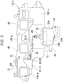
Fig. 2 is a bottom view of the intake manifold; -
Fig. 3 is a left side view of the intake manifold; -
Fig. 4 is a cross-sectional view taken along line A-A inFig. 1 ; -
Fig. 5A is a cross-sectional view of a main part showing an orifice for a blow-by gas, andFig. 5B is a cross-sectional view showing a lid member (riser) through which cooling water passes; -
Fig. 6 is a front view of an industrial-use engine; -
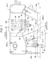
Fig. 7 is a is a right side view of the engine shown inFig. 6 ; and -
Fig. 8 is a plan view of the engine shown inFig. 6 . - Hereinafter, a preferred embodiment of the present invention relating to a blow-by gas return device is described with reference to drawings in the case where the blow-by gas return device is adopted in an industrial-use gas engine. In this industrial-use engine E, a side where a
power transmission belt 9 is disposed is defined as "front", a side where aflywheel housing 16 is disposed is defined as "rear", a side where anexhaust manifold 10 is disposed is defined as "left", and a side where anintake manifold 14 is disposed is defined as "right". - As shown in
Figs. 6 to 8 , in an industrial-use gas engine of in-line 3-cylinder (hereinafter, simply abbreviated as "engine") E, acylinder head 2 is assembled to acylinder block 1 from above, and anoil pan 4 is assembled to thecylinder block 1 from below. A lower portion of thecylinder block 1 is formed as acrankcase 1b, and an upper portion of thecylinder block 1 is formed as a cylinder 1a. A head cover (cylinder head cover) 3 is assembled to thecylinder head 2 from above. Atransmission case 5 is assembled to thecylinder block 1 from a front side. - As shown in
Figs. 6 to 8 , in a front portion of the engine E, apower transmission belt 9 is disposed. Thepower transmission belt 9 extends and is wound around adrive pulley 6, afan pulley 7 for driving a cooling fan (not shown in the drawing), and apower receiving pulley 8a of a dynamo (alternator) 8. Anexhaust manifold 10, astarter 11 and the like are mounted on a left side of the engine E. Anoil filter 13, anintake manifold 14, agas mixer 12, an ECU 17 and the like are mounted on a right side of the engine E. Threeignition coils 15 are disposed on an upper side of the engine E. Aflywheel housing 16 is mounted on a rear portion of the engine E. - As shown in
Figs. 6 to 8 , a blow-by gas return device B mounted on the engine E is configured such that a blow-by gas generated in thecrankcase 1b is introduced into an intake system k through a blow-by pipe h by way of a PCV valve (an example of a pressure control valve) 18 mounted on thehead cover 3. The blow-by pipe h includes: a first tube 19(h) which connects the head cover 3 (pressure control valve 18) and agas relay portion 21 of theintake manifold 14 to each other; and a second tube 20(h) which connects anintake body 14A of the intake manifold 14 (an example of "intake system k") and thegas relay portion 21 to each other. - The blow-by gas return device B includes: a first heating unit t1 and a second heating unit t2 for preventing freezing of the blow-by pipe h; and an
orifice 22 mounted on the gas relay portion (an example of "a passage for a blow-by gas") 21 for preventing resonance of the blow-by pipe h and the like. The first heating unit t1 uses heat of thecylinder head 2 and is mounted on thegas relay portion 21. The second heating unit t2 uses heat of cooling water, and is mounted on theintake manifold 14. Next, the blow-by gas return device B is described in detail. - As shown in
Figs. 1 to 5B , theintake manifold 14 includes; first to thirdbranched pipe portions shaped intake body 14A which communicates with these threebranched pipe portions 14a to 14c. Theintake manifold 14 also includes amounting flange 14B which integrates distal end sides of the respectivebranched pipe portions 14a to 14c to each other. Theintake manifold 14 is mounted on an engine body by threadedly mounting themounting flange 14B on thecylinder head 2 using a plurality of bolts. Amounting seat 14d for mounting thegas mixer 12 is formed on an upper side of theintake body 14A at an intermediate position in a longitudinal direction. - As shown in
Figs. 1 to 3 andFig. 5A , the first heating unit t1 includes: acylindrical hole 24 formed in a bulgingwall 23 formed in a state where the bulgingwall 23 straddles between the firstbranched pipe portion 14a and themounting flange 14B (wall portion w on a cylinder head side); and an inletjoint pipe 25 and an outletjoint pipe 26 communicating with thecylindrical hole 24. Theinlet joint pipe 25 is formed of a metal pipe mounted on thebulging wall 23 in such a manner that the metal pipe projects obliquely toward an upper left side from an upper portion of the bulgingwall 23. Theoutlet joint pipe 26 is formed of a metal sleeve mounted on thebulging wall 23 in such a manner that the metal sleeve projects toward a rear lower side from a lower portion of thebulging wall 23, and anorifice 22 is integrally formed with theoutlet joint pipe 26.Numeral 27 indicates a stopper plug for closing an open side end of thecylindrical hole 24. Left side end portions of the respectivebranched pipe portions 14a to 14c also correspond to "wall portion w on a cylinder head side". - The outlet
joint pipe 26 includes: outer peripheralmale threads 26a; an outerperipheral flange 26b; an intermediate outerperipheral portion 26c; a removal preventing outerperipheral portion 26d; a largediameter flow passage 26e formed on a proximal end side; ahexagonal hole 26f formed on a distal end side; and theorifice 22 formed of a small hole and connecting the largediameter flow passage 26e and thehexagonal hole 26f with each other. The outletjoint pipe 26 is formed using a metal material. Theorifice 22 is formed such that a cross-sectional area of theorifice 22 is apparently smaller than a cross-sectional area of thehexagonal hole 26f and a cross-sectional area of the largediameter flow passage 26e thus performing an orifice function. The outletjoint pipe 26 can be threadedly mounted on the bulging wall 23 (female threads: symbol being omitted) of the outletjoint pipe 26, and can be removed from the bulgingwall 23 by inserting a hexagonal wrench (Allen key) into thehexagonal hole 26f and rotating the hexagonal wrench. - With the use of the first heating unit t1, by allowing a blow-by gas to pass through the bulging wall 23 (cylindrical hole 24), heat of the
intake manifold 14 heated to high temperature with the heat transmitted from thecylinder head 2 can be transmitted to the blow-by pipe h and the like and a blow-by gas. Accordingly, it is possible to prevent freezing of moisture contained in the blow-by gas, and to thaw frozen moisture. Further, the bulgingwall 23 in which the passage for the blow-by gas is formed is formed in the portion which straddles between the firstbranched pipe portion 14a and the mountingflange 14B, both of those being the wall portion on a cylinder head side, and hence, it is possible to acquire an advantageous effect that heat from thecylinder head 2 can be more effectively transmitted to the blow-by pipe h and the like. - Since the
orifice 22 is formed in thegas relay portion 21, it is possible to attenuate the transmission of vibration of the engine and pulsation in the intake manifold to thePCV valve 18 by way of the blow-by pipe h (19), and it is also possible to largely change a resonance frequency. Accordingly, the present invention has an advantageous effect that it is possible to acquire an advantageous effect that the occurrence of a drawback that an unpleasant sound is generated from thePCV valve 18 or the like due to propagation of vibration or pulsation or resonance is prevented. Further, both theorifice 22 and the first heating unit t1 are formed in thegas relay portion 21 and hence, the configurations of these twoparts 22, t1 can be used in common. Accordingly, it is possible to provide the rational structure which also leads to the reduction of a manufacturing cost. - Further, the intake system k into which a blow-by gas is introduced is disposed in the
intake body 14A which is a portion disposed on a side opposite to a cylinder head side in theintake manifold 14. Accordingly, it is possible to acquire an advantageous effect that a blow-by gas can be distributed to the branchedpipe portions 14a to 14c mounted on respective cylinders in a well-balanced manner. For example, in a unit where an intake manifold has the structure where branched pipe portions are not provided or are extremely short or a blow-by gas is returned to a mountingflange 14B portion, there is a possibility of occurrence of a drawback that a blow-by gas is supplied to any one of cylinders in a non-uniform manner. However, with the configuration of the present invention, such a drawback can be eliminated or suppressed. - That is, the
orifice 22 mounted in a gas path through which a blow-by gas flows is mounted on the wall portion w of theintake manifold 14 on a cylinder head side. Thepassage 21 for a blow-by gas is formed in the wall portion w on the cylinder head side. Theorifice 22 is formed in thejoint pipe 26 which is mounted in thepassage 21 for a blow-by gas for connecting the blow-by pipe h with thepassage 21 for a blow-by gas communicably. Further, a portion p into which a blow-by gas is introduced is disposed in the box-shapedintake body 14A which is a portion of theintake manifold 14 and is disposed on a side opposite to a cylinder head side and communicates with all branchedpipe portions 14a to 14c. - All of the
first tube 19, the inletjoint pipe 25, the bulgingwall 23, the outletjoint pipe 26, thesecond tube 20, a return pipe 29 (described later) and the like are gas paths (symbols being omitted). - As shown in
Figs. 1 to 4 andFig. 5B , areturn flow portion 28 for a blow-by gas is formed in a lower portion of a longitudinally center portion of theintake body 14A at a position close to a cylinder head side (left side). Thereturn pipe 29 formed of a metal pipe and into which the second tube 20 (blow-by pipe h) is fitted is mounted on thereturn flow portion 28 which is a wall portion forming theintake manifold 14 and having a large wall thickness such that thereturn pipe 29 projects from thereturn flow portion 28. The configuration is adopted where a blow-by gas supplied from thegas relay portion 21 through thesecond tube 20 is returned via thereturn flow portion 28 to theintake body 14A. - A
flow passage 30 which is a passage for cooling water is formed in thereturn flow portion 28. Theflow passage 30 is formed as a space portion which is surrounded by a lid member (riser) 31 detachably mounted on abottom wall portion 28A of thereturn flow portion 28 and thebottom wall portion 28A. Aninlet 32 and anoutlet 33 for cooling water communicated with theflow passage 30 are formed in thereturn flow portion 28. Theinlet 32 for cooling water is formed in the form of abent pipe 32 which is mounted on abottom wall 31A of thelid member 31 in a downwardly projecting manner, and theoutlet 33 for cooling water is formed in the form of astraight pipe 33 which is mounted on aperipheral wall 31B of thelid member 31 in a projecting manner. - Cooling water enters the flat
cylindrical flow passage 30 from thebent pipe 32 and is discharged from thestraight pipe 33. Cooling water which flows through theflow passage 30 warms thereturn flow portion 28 from thebottom wall portion 28A, and also warms a blow-by gas which passes through thereturn flow portion 28. Accordingly, the second heating unit t2 is formed of thereturn flow portion 28, thelid member 31 and the like. InFig. 4 ,symbol 34 indicates a large circular hole formed in the mountingseat 14d, and numeral 36 indicates a closing plug which closes atemporary hole 35 formed in a lower end portion of theintake body 14A. - The second heating unit t2 which uses cooling water as a heat source is formed on the
return flow portion 28 which is a return portion from which a brow-by gas returns to the intake system k through the blow-by pipe h. Accordingly, thereturn flow portion 28 and a blow-by gas which flows in thereturn flow portion 28 are warmed by heat of cooling water so that freezing of the blow-by pipe h (a terminal portion of the second tube 20) and a blow-by path is prevented or freezing is thawed whereby it is possible to expect an effect of eliminating closing by freezing. The second heating unit t2 is disposed on a lower side of thereturn flow portion 28. This structure is preferable from a viewpoint of conduction of heat. - The
lid member 31 which is a part for forming the second heating unit t2 is detachably mounted on thebottom wall portion 28A by two bolts, and theinlet 32 and theoutlet 33 for cooling water are formed in thelid member 31 which forms a side detachably mounted on thebottom wall portion 28A. Accordingly, when the blow-by gas return device adopts the specification where the second heating unit t2 is unnecessary, thelid member 31 may not be assembled or may be removed. Further, in the case where thelid member 31 is removed, thebent pipe 32 and thestraight pipe 33 are also removed. Accordingly, it is possible to adopt a rational unit where there are almost no wasteful parts (lid member 31 and the like) in the specification where the second heating unit t2 is unnecessary. - A
pressure control valve 18 may be a valve other than a PCV valve such as a breather valve. The intake system k may be mounted on a portion other than theintake manifold 14 such as an air cleaner or an intake duct. - The present invention is applicable to a blow-by gas return device attached to various engines such as a diesel engine and a gasoline engine having cylinders other than 3-cylinders, that is, 2-cylinders or 5-cylinders.
Claims (5)
- A blow-by gas return device comprising:a gas path which is configured to introduce a blow-by gas generated in a crankcase into an intake system through an inside of a head cover, a pressure control valve and a blow-by pipe; andan orifice provided to the blow-by pipe, the orifice mounted on a wall portion of an intake manifold on a cylinder head side.
- The blow-by gas return device according to claim 1, wherein a passage for the blow-by gas is formed in the wall portion on the cylinder head side, and the orifice is formed on a joint pipe mounted on the passage for the blow-by gas for communicably connecting the blow-by pipe with the passage for the blow-by gas.
- The blow-by gas return device according to claim 1 or 2, wherein the wall portion on the cylinder head side has a mounting flange to be fixed to a cylinder head by a bolt.
- The blow-by gas return device according to any one of claims 1 to 3, wherein the intake system to which the blow-by gas is introduced forms the intake manifold, and the intake system is mounted on a portion of the intake manifold on a side opposite to the cylinder head side.
- The blow-by gas return device according to any one of claims 1 to 4, wherein the blow-by gas return device is used for an in-line 3-cylinder engine.
Applications Claiming Priority (1)
| Application Number | Priority Date | Filing Date | Title |
|---|---|---|---|
| JP2017127346A JP6782200B2 (en) | 2017-06-29 | 2017-06-29 | Blow-by gas reflux device |
Publications (3)
| Publication Number | Publication Date |
|---|---|
| EP3421743A2 true EP3421743A2 (en) | 2019-01-02 |
| EP3421743A3 EP3421743A3 (en) | 2019-01-16 |
| EP3421743B1 EP3421743B1 (en) | 2022-08-17 |
Family
ID=62091778
Family Applications (1)
| Application Number | Title | Priority Date | Filing Date |
|---|---|---|---|
| EP18170155.8A Active EP3421743B1 (en) | 2017-06-29 | 2018-04-30 | Blow-by gas return device |
Country Status (3)
| Country | Link |
|---|---|
| US (1) | US10975742B2 (en) |
| EP (1) | EP3421743B1 (en) |
| JP (1) | JP6782200B2 (en) |
Families Citing this family (3)
| Publication number | Priority date | Publication date | Assignee | Title |
|---|---|---|---|---|
| JP6538006B2 (en) * | 2016-06-28 | 2019-07-03 | 株式会社クボタ | Blowby gas return structure |
| JP2020023939A (en) * | 2018-08-08 | 2020-02-13 | いすゞ自動車株式会社 | Blowby gas atmosphere release device |
| JP6683774B2 (en) * | 2018-08-24 | 2020-04-22 | 本田技研工業株式会社 | air cleaner |
Citations (1)
| Publication number | Priority date | Publication date | Assignee | Title |
|---|---|---|---|---|
| JP2003090206A (en) | 2001-09-18 | 2003-03-28 | Yanmar Co Ltd | Breather device for engine |
Family Cites Families (17)
| Publication number | Priority date | Publication date | Assignee | Title |
|---|---|---|---|---|
| US3280808A (en) * | 1965-01-04 | 1966-10-25 | Ford Motor Co | Engine crankcase ventilating system |
| US3494339A (en) * | 1967-06-14 | 1970-02-10 | John Jame Fernandez | Self-cleaning smog control filter and fire trap for internal combustion engines |
| US4169432A (en) * | 1977-03-31 | 1979-10-02 | Ford Motor Company | Integrated PCV valve and oil filler cap |
| JPH0756209B2 (en) * | 1985-04-19 | 1995-06-14 | マツダ株式会社 | Multi-cylinder engine intake system |
| JPH0426644Y2 (en) * | 1985-09-27 | 1992-06-26 | ||
| JPH075210Y2 (en) * | 1988-01-26 | 1995-02-08 | ダイハツ工業株式会社 | Blow-by gas recirculation device |
| US6234154B1 (en) * | 2000-06-12 | 2001-05-22 | General Motors Corporation | Integral PCV system |
| ATE508260T1 (en) * | 2001-09-18 | 2011-05-15 | Yanmar Co Ltd | ENGINE BLEEDING DEVICE |
| KR100527441B1 (en) * | 2002-06-12 | 2005-11-09 | 현대자동차주식회사 | Apparatus for distributing blow-by gas for engine |
| KR100645576B1 (en) * | 2004-07-06 | 2006-11-15 | 현대자동차주식회사 | Air intake system for vehicle |
| WO2006102510A2 (en) * | 2005-03-24 | 2006-09-28 | Cooper-Standard Automotive, Inc. | Positive crankcase ventilation valve assembly with a vacuum pulsation dampener |
| JP2008101472A (en) * | 2006-10-17 | 2008-05-01 | Yamaha Motor Co Ltd | Spark ignition multicylinder engine |
| JP5478399B2 (en) * | 2009-09-30 | 2014-04-23 | 株式会社クボタ | Engine blow-by gas recirculation system |
| JP5490562B2 (en) * | 2010-02-19 | 2014-05-14 | 愛三工業株式会社 | PCV valve mounting structure |
| KR101234649B1 (en) * | 2010-11-25 | 2013-02-19 | 현대자동차주식회사 | Pcv anti-freezing apparattus for 2 cylinder engine |
| JP2014020279A (en) * | 2012-07-18 | 2014-02-03 | Nippon Sharyo Seizo Kaisha Ltd | Blow-by gas recirculation device |
| KR101700527B1 (en) * | 2015-09-18 | 2017-01-26 | 주식회사 현대케피코 | Intake manifold for vehicle with unified gas flow path |
-
2017
- 2017-06-29 JP JP2017127346A patent/JP6782200B2/en active Active
-
2018
- 2018-04-30 EP EP18170155.8A patent/EP3421743B1/en active Active
- 2018-05-21 US US15/985,535 patent/US10975742B2/en active Active
Patent Citations (1)
| Publication number | Priority date | Publication date | Assignee | Title |
|---|---|---|---|---|
| JP2003090206A (en) | 2001-09-18 | 2003-03-28 | Yanmar Co Ltd | Breather device for engine |
Also Published As
| Publication number | Publication date |
|---|---|
| US10975742B2 (en) | 2021-04-13 |
| JP2019011686A (en) | 2019-01-24 |
| EP3421743B1 (en) | 2022-08-17 |
| JP6782200B2 (en) | 2020-11-11 |
| EP3421743A3 (en) | 2019-01-16 |
| US20190003357A1 (en) | 2019-01-03 |
Similar Documents
| Publication | Publication Date | Title |
|---|---|---|
| EP3421743B1 (en) | Blow-by gas return device | |
| US6234154B1 (en) | Integral PCV system | |
| US9027537B2 (en) | PCV valve installation structure | |
| US10612499B2 (en) | Air intake apparatus | |
| JP3772871B2 (en) | Intake device for internal combustion engine | |
| US20100255737A1 (en) | Outboard motor | |
| JP4020059B2 (en) | Intake device for internal combustion engine | |
| JP4791305B2 (en) | Water-cooled multi-cylinder engine | |
| US20100313860A1 (en) | Apparatus for removal of oil from positive crankcase ventilation system | |
| JP2014190296A (en) | Internal combustion engine | |
| JP6225885B2 (en) | Blowby gas recirculation system | |
| JP2009209813A (en) | Blow-by gas recirculation device of engine | |
| JP7103928B2 (en) | Blow-by gas recirculation device | |
| JP6795465B2 (en) | Blow-by gas reflux device | |
| JP2013079623A (en) | Oil jet structure of engine | |
| US20200018199A1 (en) | Oil supply device | |
| JP7291642B2 (en) | Engine with blow-by gas recirculation device | |
| JPH1193635A (en) | Breather device for engine | |
| JP7092690B2 (en) | Engine with blow-by gas recirculation device | |
| US7571704B2 (en) | Internal combustion engine provided with electrical equipment holder | |
| JP7081976B2 (en) | Engine with blow-by gas recirculation device | |
| US6782864B2 (en) | Mount structure for an engine accessory | |
| CN109026321B (en) | Cooling oil passage structure of engine | |
| JP4795905B2 (en) | Water-cooled engine | |
| JP2007231896A (en) | Direct injection type engine |
Legal Events
| Date | Code | Title | Description |
|---|---|---|---|
| PUAI | Public reference made under article 153(3) epc to a published international application that has entered the european phase |
Free format text: ORIGINAL CODE: 0009012 |
|
| STAA | Information on the status of an ep patent application or granted ep patent |
Free format text: STATUS: THE APPLICATION HAS BEEN PUBLISHED |
|
| PUAL | Search report despatched |
Free format text: ORIGINAL CODE: 0009013 |
|
| AK | Designated contracting states |
Kind code of ref document: A2 Designated state(s): AL AT BE BG CH CY CZ DE DK EE ES FI FR GB GR HR HU IE IS IT LI LT LU LV MC MK MT NL NO PL PT RO RS SE SI SK SM TR |
|
| AX | Request for extension of the european patent |
Extension state: BA ME |
|
| AK | Designated contracting states |
Kind code of ref document: A3 Designated state(s): AL AT BE BG CH CY CZ DE DK EE ES FI FR GB GR HR HU IE IS IT LI LT LU LV MC MK MT NL NO PL PT RO RS SE SI SK SM TR |
|
| AX | Request for extension of the european patent |
Extension state: BA ME |
|
| RIC1 | Information provided on ipc code assigned before grant |
Ipc: F01M 13/02 20060101AFI20181211BHEP Ipc: F01M 13/00 20060101ALN20181211BHEP Ipc: F02M 35/10 20060101ALI20181211BHEP |
|
| STAA | Information on the status of an ep patent application or granted ep patent |
Free format text: STATUS: REQUEST FOR EXAMINATION WAS MADE |
|
| 17P | Request for examination filed |
Effective date: 20190704 |
|
| RBV | Designated contracting states (corrected) |
Designated state(s): AL AT BE BG CH CY CZ DE DK EE ES FI FR GB GR HR HU IE IS IT LI LT LU LV MC MK MT NL NO PL PT RO RS SE SI SK SM TR |
|
| STAA | Information on the status of an ep patent application or granted ep patent |
Free format text: STATUS: EXAMINATION IS IN PROGRESS |
|
| STAA | Information on the status of an ep patent application or granted ep patent |
Free format text: STATUS: EXAMINATION IS IN PROGRESS |
|
| 17Q | First examination report despatched |
Effective date: 20201120 |
|
| STAA | Information on the status of an ep patent application or granted ep patent |
Free format text: STATUS: EXAMINATION IS IN PROGRESS |
|
| GRAP | Despatch of communication of intention to grant a patent |
Free format text: ORIGINAL CODE: EPIDOSNIGR1 |
|
| STAA | Information on the status of an ep patent application or granted ep patent |
Free format text: STATUS: GRANT OF PATENT IS INTENDED |
|
| RIC1 | Information provided on ipc code assigned before grant |
Ipc: F01M 13/00 20060101ALN20220308BHEP Ipc: F02M 35/10 20060101ALI20220308BHEP Ipc: F02M 25/06 20160101ALI20220308BHEP Ipc: F01M 13/04 20060101ALI20220308BHEP Ipc: F01M 13/02 20060101AFI20220308BHEP |
|
| INTG | Intention to grant announced |
Effective date: 20220401 |
|
| GRAS | Grant fee paid |
Free format text: ORIGINAL CODE: EPIDOSNIGR3 |
|
| GRAA | (expected) grant |
Free format text: ORIGINAL CODE: 0009210 |
|
| STAA | Information on the status of an ep patent application or granted ep patent |
Free format text: STATUS: THE PATENT HAS BEEN GRANTED |
|
| AK | Designated contracting states |
Kind code of ref document: B1 Designated state(s): AL AT BE BG CH CY CZ DE DK EE ES FI FR GB GR HR HU IE IS IT LI LT LU LV MC MK MT NL NO PL PT RO RS SE SI SK SM TR |
|
| REG | Reference to a national code |
Ref country code: CH Ref legal event code: EP |
|
| REG | Reference to a national code |
Ref country code: DE Ref legal event code: R096 Ref document number: 602018039308 Country of ref document: DE |
|
| REG | Reference to a national code |
Ref country code: IE Ref legal event code: FG4D |
|
| REG | Reference to a national code |
Ref country code: AT Ref legal event code: REF Ref document number: 1512329 Country of ref document: AT Kind code of ref document: T Effective date: 20220915 |
|
| REG | Reference to a national code |
Ref country code: NL Ref legal event code: MP Effective date: 20220817 |
|
| REG | Reference to a national code |
Ref country code: LT Ref legal event code: MG9D |
|
| PG25 | Lapsed in a contracting state [announced via postgrant information from national office to epo] |
Ref country code: SE Free format text: LAPSE BECAUSE OF FAILURE TO SUBMIT A TRANSLATION OF THE DESCRIPTION OR TO PAY THE FEE WITHIN THE PRESCRIBED TIME-LIMIT Effective date: 20220817 Ref country code: RS Free format text: LAPSE BECAUSE OF FAILURE TO SUBMIT A TRANSLATION OF THE DESCRIPTION OR TO PAY THE FEE WITHIN THE PRESCRIBED TIME-LIMIT Effective date: 20220817 Ref country code: PT Free format text: LAPSE BECAUSE OF FAILURE TO SUBMIT A TRANSLATION OF THE DESCRIPTION OR TO PAY THE FEE WITHIN THE PRESCRIBED TIME-LIMIT Effective date: 20221219 Ref country code: NO Free format text: LAPSE BECAUSE OF FAILURE TO SUBMIT A TRANSLATION OF THE DESCRIPTION OR TO PAY THE FEE WITHIN THE PRESCRIBED TIME-LIMIT Effective date: 20221117 Ref country code: NL Free format text: LAPSE BECAUSE OF FAILURE TO SUBMIT A TRANSLATION OF THE DESCRIPTION OR TO PAY THE FEE WITHIN THE PRESCRIBED TIME-LIMIT Effective date: 20220817 Ref country code: LV Free format text: LAPSE BECAUSE OF FAILURE TO SUBMIT A TRANSLATION OF THE DESCRIPTION OR TO PAY THE FEE WITHIN THE PRESCRIBED TIME-LIMIT Effective date: 20220817 Ref country code: LT Free format text: LAPSE BECAUSE OF FAILURE TO SUBMIT A TRANSLATION OF THE DESCRIPTION OR TO PAY THE FEE WITHIN THE PRESCRIBED TIME-LIMIT Effective date: 20220817 Ref country code: FI Free format text: LAPSE BECAUSE OF FAILURE TO SUBMIT A TRANSLATION OF THE DESCRIPTION OR TO PAY THE FEE WITHIN THE PRESCRIBED TIME-LIMIT Effective date: 20220817 |
|
| REG | Reference to a national code |
Ref country code: AT Ref legal event code: MK05 Ref document number: 1512329 Country of ref document: AT Kind code of ref document: T Effective date: 20220817 |
|
| PG25 | Lapsed in a contracting state [announced via postgrant information from national office to epo] |
Ref country code: PL Free format text: LAPSE BECAUSE OF FAILURE TO SUBMIT A TRANSLATION OF THE DESCRIPTION OR TO PAY THE FEE WITHIN THE PRESCRIBED TIME-LIMIT Effective date: 20220817 Ref country code: IS Free format text: LAPSE BECAUSE OF FAILURE TO SUBMIT A TRANSLATION OF THE DESCRIPTION OR TO PAY THE FEE WITHIN THE PRESCRIBED TIME-LIMIT Effective date: 20221217 Ref country code: HR Free format text: LAPSE BECAUSE OF FAILURE TO SUBMIT A TRANSLATION OF THE DESCRIPTION OR TO PAY THE FEE WITHIN THE PRESCRIBED TIME-LIMIT Effective date: 20220817 Ref country code: GR Free format text: LAPSE BECAUSE OF FAILURE TO SUBMIT A TRANSLATION OF THE DESCRIPTION OR TO PAY THE FEE WITHIN THE PRESCRIBED TIME-LIMIT Effective date: 20221118 |
|
| PG25 | Lapsed in a contracting state [announced via postgrant information from national office to epo] |
Ref country code: SM Free format text: LAPSE BECAUSE OF FAILURE TO SUBMIT A TRANSLATION OF THE DESCRIPTION OR TO PAY THE FEE WITHIN THE PRESCRIBED TIME-LIMIT Effective date: 20220817 Ref country code: RO Free format text: LAPSE BECAUSE OF FAILURE TO SUBMIT A TRANSLATION OF THE DESCRIPTION OR TO PAY THE FEE WITHIN THE PRESCRIBED TIME-LIMIT Effective date: 20220817 Ref country code: ES Free format text: LAPSE BECAUSE OF FAILURE TO SUBMIT A TRANSLATION OF THE DESCRIPTION OR TO PAY THE FEE WITHIN THE PRESCRIBED TIME-LIMIT Effective date: 20220817 Ref country code: DK Free format text: LAPSE BECAUSE OF FAILURE TO SUBMIT A TRANSLATION OF THE DESCRIPTION OR TO PAY THE FEE WITHIN THE PRESCRIBED TIME-LIMIT Effective date: 20220817 Ref country code: CZ Free format text: LAPSE BECAUSE OF FAILURE TO SUBMIT A TRANSLATION OF THE DESCRIPTION OR TO PAY THE FEE WITHIN THE PRESCRIBED TIME-LIMIT Effective date: 20220817 Ref country code: AT Free format text: LAPSE BECAUSE OF FAILURE TO SUBMIT A TRANSLATION OF THE DESCRIPTION OR TO PAY THE FEE WITHIN THE PRESCRIBED TIME-LIMIT Effective date: 20220817 |
|
| PGFP | Annual fee paid to national office [announced via postgrant information from national office to epo] |
Ref country code: FR Payment date: 20230309 Year of fee payment: 6 |
|
| REG | Reference to a national code |
Ref country code: DE Ref legal event code: R097 Ref document number: 602018039308 Country of ref document: DE |
|
| PG25 | Lapsed in a contracting state [announced via postgrant information from national office to epo] |
Ref country code: SK Free format text: LAPSE BECAUSE OF FAILURE TO SUBMIT A TRANSLATION OF THE DESCRIPTION OR TO PAY THE FEE WITHIN THE PRESCRIBED TIME-LIMIT Effective date: 20220817 Ref country code: EE Free format text: LAPSE BECAUSE OF FAILURE TO SUBMIT A TRANSLATION OF THE DESCRIPTION OR TO PAY THE FEE WITHIN THE PRESCRIBED TIME-LIMIT Effective date: 20220817 |
|
| PLBE | No opposition filed within time limit |
Free format text: ORIGINAL CODE: 0009261 |
|
| STAA | Information on the status of an ep patent application or granted ep patent |
Free format text: STATUS: NO OPPOSITION FILED WITHIN TIME LIMIT |
|
| PG25 | Lapsed in a contracting state [announced via postgrant information from national office to epo] |
Ref country code: AL Free format text: LAPSE BECAUSE OF FAILURE TO SUBMIT A TRANSLATION OF THE DESCRIPTION OR TO PAY THE FEE WITHIN THE PRESCRIBED TIME-LIMIT Effective date: 20220817 |
|
| 26N | No opposition filed |
Effective date: 20230519 |
|
| PGFP | Annual fee paid to national office [announced via postgrant information from national office to epo] |
Ref country code: DE Payment date: 20230307 Year of fee payment: 6 |
|
| PG25 | Lapsed in a contracting state [announced via postgrant information from national office to epo] |
Ref country code: SI Free format text: LAPSE BECAUSE OF FAILURE TO SUBMIT A TRANSLATION OF THE DESCRIPTION OR TO PAY THE FEE WITHIN THE PRESCRIBED TIME-LIMIT Effective date: 20220817 |
|
| REG | Reference to a national code |
Ref country code: CH Ref legal event code: PL |
|
| PG25 | Lapsed in a contracting state [announced via postgrant information from national office to epo] |
Ref country code: LU Free format text: LAPSE BECAUSE OF NON-PAYMENT OF DUE FEES Effective date: 20230430 |
|
| REG | Reference to a national code |
Ref country code: BE Ref legal event code: MM Effective date: 20230430 |
|
| PG25 | Lapsed in a contracting state [announced via postgrant information from national office to epo] |
Ref country code: MC Free format text: LAPSE BECAUSE OF FAILURE TO SUBMIT A TRANSLATION OF THE DESCRIPTION OR TO PAY THE FEE WITHIN THE PRESCRIBED TIME-LIMIT Effective date: 20220817 |
|
| PG25 | Lapsed in a contracting state [announced via postgrant information from national office to epo] |
Ref country code: MC Free format text: LAPSE BECAUSE OF FAILURE TO SUBMIT A TRANSLATION OF THE DESCRIPTION OR TO PAY THE FEE WITHIN THE PRESCRIBED TIME-LIMIT Effective date: 20220817 Ref country code: LI Free format text: LAPSE BECAUSE OF NON-PAYMENT OF DUE FEES Effective date: 20230430 Ref country code: CH Free format text: LAPSE BECAUSE OF NON-PAYMENT OF DUE FEES Effective date: 20230430 |
|
| REG | Reference to a national code |
Ref country code: IE Ref legal event code: MM4A |
|
| PG25 | Lapsed in a contracting state [announced via postgrant information from national office to epo] |
Ref country code: BE Free format text: LAPSE BECAUSE OF NON-PAYMENT OF DUE FEES Effective date: 20230430 |
|
| PG25 | Lapsed in a contracting state [announced via postgrant information from national office to epo] |
Ref country code: IE Free format text: LAPSE BECAUSE OF NON-PAYMENT OF DUE FEES Effective date: 20230430 |
|
| PG25 | Lapsed in a contracting state [announced via postgrant information from national office to epo] |
Ref country code: IE Free format text: LAPSE BECAUSE OF NON-PAYMENT OF DUE FEES Effective date: 20230430 |
|
| PGFP | Annual fee paid to national office [announced via postgrant information from national office to epo] |
Ref country code: GB Payment date: 20240307 Year of fee payment: 7 |