EP3421389A1 - Method for vacuum packing high-purity tin and vacuum-packed high-purity tin - Google Patents
Method for vacuum packing high-purity tin and vacuum-packed high-purity tin Download PDFInfo
- Publication number
- EP3421389A1 EP3421389A1 EP17756386.3A EP17756386A EP3421389A1 EP 3421389 A1 EP3421389 A1 EP 3421389A1 EP 17756386 A EP17756386 A EP 17756386A EP 3421389 A1 EP3421389 A1 EP 3421389A1
- Authority
- EP
- European Patent Office
- Prior art keywords
- vacuum
- high purity
- purity metal
- packed
- metal
- Prior art date
- Legal status (The legal status is an assumption and is not a legal conclusion. Google has not performed a legal analysis and makes no representation as to the accuracy of the status listed.)
- Granted
Links
Images



Classifications
-
- B—PERFORMING OPERATIONS; TRANSPORTING
- B65—CONVEYING; PACKING; STORING; HANDLING THIN OR FILAMENTARY MATERIAL
- B65D—CONTAINERS FOR STORAGE OR TRANSPORT OF ARTICLES OR MATERIALS, e.g. BAGS, BARRELS, BOTTLES, BOXES, CANS, CARTONS, CRATES, DRUMS, JARS, TANKS, HOPPERS, FORWARDING CONTAINERS; ACCESSORIES, CLOSURES, OR FITTINGS THEREFOR; PACKAGING ELEMENTS; PACKAGES
- B65D81/00—Containers, packaging elements, or packages, for contents presenting particular transport or storage problems, or adapted to be used for non-packaging purposes after removal of contents
- B65D81/18—Containers, packaging elements, or packages, for contents presenting particular transport or storage problems, or adapted to be used for non-packaging purposes after removal of contents providing specific environment for contents, e.g. temperature above or below ambient
- B65D81/20—Containers, packaging elements, or packages, for contents presenting particular transport or storage problems, or adapted to be used for non-packaging purposes after removal of contents providing specific environment for contents, e.g. temperature above or below ambient under vacuum or superatmospheric pressure, or in a special atmosphere, e.g. of inert gas
- B65D81/2007—Containers, packaging elements, or packages, for contents presenting particular transport or storage problems, or adapted to be used for non-packaging purposes after removal of contents providing specific environment for contents, e.g. temperature above or below ambient under vacuum or superatmospheric pressure, or in a special atmosphere, e.g. of inert gas under vacuum
- B65D81/2023—Containers, packaging elements, or packages, for contents presenting particular transport or storage problems, or adapted to be used for non-packaging purposes after removal of contents providing specific environment for contents, e.g. temperature above or below ambient under vacuum or superatmospheric pressure, or in a special atmosphere, e.g. of inert gas under vacuum in a flexible container
-
- B—PERFORMING OPERATIONS; TRANSPORTING
- B65—CONVEYING; PACKING; STORING; HANDLING THIN OR FILAMENTARY MATERIAL
- B65B—MACHINES, APPARATUS OR DEVICES FOR, OR METHODS OF, PACKAGING ARTICLES OR MATERIALS; UNPACKING
- B65B11/00—Wrapping, e.g. partially or wholly enclosing, articles or quantities of material, in strips, sheets or blanks, of flexible material
- B65B11/50—Enclosing articles, or quantities of material, by disposing contents between two sheets, e.g. pocketed sheets, and securing their opposed free margins
- B65B11/52—Enclosing articles, or quantities of material, by disposing contents between two sheets, e.g. pocketed sheets, and securing their opposed free margins one sheet being rendered plastic, e.g. by heating, and forced by fluid pressure, e.g. vacuum, into engagement with the other sheet and contents, e.g. skin-, blister-, or bubble- packaging
-
- B—PERFORMING OPERATIONS; TRANSPORTING
- B65—CONVEYING; PACKING; STORING; HANDLING THIN OR FILAMENTARY MATERIAL
- B65D—CONTAINERS FOR STORAGE OR TRANSPORT OF ARTICLES OR MATERIALS, e.g. BAGS, BARRELS, BOTTLES, BOXES, CANS, CARTONS, CRATES, DRUMS, JARS, TANKS, HOPPERS, FORWARDING CONTAINERS; ACCESSORIES, CLOSURES, OR FITTINGS THEREFOR; PACKAGING ELEMENTS; PACKAGES
- B65D75/00—Packages comprising articles or materials partially or wholly enclosed in strips, sheets, blanks, tubes or webs of flexible sheet material, e.g. in folded wrappers
- B65D75/26—Articles or materials wholly enclosed in laminated sheets or wrapper blanks
-
- B—PERFORMING OPERATIONS; TRANSPORTING
- B65—CONVEYING; PACKING; STORING; HANDLING THIN OR FILAMENTARY MATERIAL
- B65D—CONTAINERS FOR STORAGE OR TRANSPORT OF ARTICLES OR MATERIALS, e.g. BAGS, BARRELS, BOTTLES, BOXES, CANS, CARTONS, CRATES, DRUMS, JARS, TANKS, HOPPERS, FORWARDING CONTAINERS; ACCESSORIES, CLOSURES, OR FITTINGS THEREFOR; PACKAGING ELEMENTS; PACKAGES
- B65D81/00—Containers, packaging elements, or packages, for contents presenting particular transport or storage problems, or adapted to be used for non-packaging purposes after removal of contents
- B65D81/18—Containers, packaging elements, or packages, for contents presenting particular transport or storage problems, or adapted to be used for non-packaging purposes after removal of contents providing specific environment for contents, e.g. temperature above or below ambient
- B65D81/20—Containers, packaging elements, or packages, for contents presenting particular transport or storage problems, or adapted to be used for non-packaging purposes after removal of contents providing specific environment for contents, e.g. temperature above or below ambient under vacuum or superatmospheric pressure, or in a special atmosphere, e.g. of inert gas
-
- B—PERFORMING OPERATIONS; TRANSPORTING
- B65—CONVEYING; PACKING; STORING; HANDLING THIN OR FILAMENTARY MATERIAL
- B65D—CONTAINERS FOR STORAGE OR TRANSPORT OF ARTICLES OR MATERIALS, e.g. BAGS, BARRELS, BOTTLES, BOXES, CANS, CARTONS, CRATES, DRUMS, JARS, TANKS, HOPPERS, FORWARDING CONTAINERS; ACCESSORIES, CLOSURES, OR FITTINGS THEREFOR; PACKAGING ELEMENTS; PACKAGES
- B65D81/00—Containers, packaging elements, or packages, for contents presenting particular transport or storage problems, or adapted to be used for non-packaging purposes after removal of contents
- B65D81/18—Containers, packaging elements, or packages, for contents presenting particular transport or storage problems, or adapted to be used for non-packaging purposes after removal of contents providing specific environment for contents, e.g. temperature above or below ambient
- B65D81/20—Containers, packaging elements, or packages, for contents presenting particular transport or storage problems, or adapted to be used for non-packaging purposes after removal of contents providing specific environment for contents, e.g. temperature above or below ambient under vacuum or superatmospheric pressure, or in a special atmosphere, e.g. of inert gas
- B65D81/2007—Containers, packaging elements, or packages, for contents presenting particular transport or storage problems, or adapted to be used for non-packaging purposes after removal of contents providing specific environment for contents, e.g. temperature above or below ambient under vacuum or superatmospheric pressure, or in a special atmosphere, e.g. of inert gas under vacuum
-
- B—PERFORMING OPERATIONS; TRANSPORTING
- B65—CONVEYING; PACKING; STORING; HANDLING THIN OR FILAMENTARY MATERIAL
- B65D—CONTAINERS FOR STORAGE OR TRANSPORT OF ARTICLES OR MATERIALS, e.g. BAGS, BARRELS, BOTTLES, BOXES, CANS, CARTONS, CRATES, DRUMS, JARS, TANKS, HOPPERS, FORWARDING CONTAINERS; ACCESSORIES, CLOSURES, OR FITTINGS THEREFOR; PACKAGING ELEMENTS; PACKAGES
- B65D85/00—Containers, packaging elements or packages, specially adapted for particular articles or materials
- B65D85/50—Containers, packaging elements or packages, specially adapted for particular articles or materials for living organisms, articles or materials sensitive to changes of environment or atmospheric conditions, e.g. land animals, birds, fish, water plants, non-aquatic plants, flower bulbs, cut flowers or foliage
Definitions
- the present invention relates to a method for vacuum-packing high purity tin and a vacuum-packed high purity tin.
- a high purity metal product that is susceptible to oxidation such as high purity tin product, is vacuum-packed to prevent oxidation and contamination and then shipped.
- Polyethylene with lower oxygen permeability or aluminum vapor deposited polyethylene film is used as a vacuum packing film.
- the vacuum-packed and shipped product is used after opening the packing. If washing operation such as etching is carried out after opening the vacuum packing, oxidation of the product will proceed with the operation. Therefore, the high purity metal product that is susceptible to oxidation, such as the high purity thin product, is shipped such that it can be immediately used as it is after opening the vacuum packing. For example, the product is then immediately melted and used for subsequent precision machining.
- Patent Document 1 describes an art relating to a packed high purity target. It discloses that when packing the high purity target using a polyethylene bag produced by molding polyethylene with clean air having an air cleanliness of class 6 or less, the removed target can achieve both stability at the time of initiating use in sputtering and prolonged life time characteristics.
- Patent Document 1 Japanese Patent Application Publication No. 2001-240959 A
- the present inventors was attempted to further purify high purity tin. However, even if the further purification was advanced, heating and melting the shipped high purity tin product often resulted in contamination of carbon impurities in the molten liquid, which caused undesirable particle formation.
- the present inventors was intensively studied to solve the above problems and tried to further purify the high purity tin, but could not completely avoid some degree of contamination of carbon impurities.
- the present inventors has completely changed the viewpoint of research and development and then observed the surface of the high purity tin immediately prior to heating and melting by means of an electron microscope.
- the present inventors have found that fine grains which are not visually observed are present, and components of the grains contain carbon when analyzed.
- the present inventors have then found that when vacuum-packing high purity tin by a fluorocarbon resin sheet interposed between a polyethylene sheet and tin, the high purity tin product has extremely reduced carbon deposits when opening the packing, and have completed the present invention.
- the present invention includes the following aspects:
- a high purity metal product (a high purity tin product) containing no undesirable carbon impurities can be obtained.
- the vacuum-packed high purity metal product (a vacuum-packed high purity tin product) according to the present invention can be used immediately after opening the vacuum packing without washing or the like, for example, it can be immediately heated and melted to prepare a molten metal of the high purity metal (tin), and can use the vacuum-packed high purity metal product according to the present invention as a molten metal for an ultrafine processing apparatus such as an LSI or the like.
- the molten metal has extremely reduced carbon impurities.
- the vacuum-packed high purity metal article according to the present invention can be produced by vacuum-packing a high purity metal using a method including the steps of covering at least a part of a surface of the high purity metal with a fluorocarbon resin sheet; and vacuum-packing the high-purity metal with at least a part of the surface covered with the fluorocarbon resin sheet by a vacuum packing film.
- the vacuum packing according to the present invention can be suitably used for high purity metals that are susceptible to oxidation.
- high purity metals include, for example, high purity tin (Sn), bismuth (Bi) and copper (Cu).
- high purity Sn may be used. It is important for such a high purity metal to reduce carbon impurities, in order to use the high purity metal as it is immediately after opening the vacuum packing, for example to melt the high purity metal immediately after opening the vacuum packing, without further performing washing operation such as etching, and then employ the high purity metal according to the present invention as a molten metal.
- the advantage of the present invention can be provided without no particular limitation as long as the purity of the high purity metal is of such a degree that the vacuum packing is used, for example, metals having a purity such as 2N (99%), 3N (99.9%), 4N (99.99%), 5N (99.999%), and 6N (99.9999%) may be used.
- the shape of the high purity metal is not particularly limited as long as it has a shape capable carrying out the operation of vacuum packing according to the present invention.
- Preferable shapes include, for example, shapes such as a substantially columnar shape, a columnar shape, a rectangular parallelepiped shape, and a cubic shape. Preferably, it may be substantially columnar.
- a person skilled in the art would be able to appropriately perform the vacuum packing depending on the shape of the high purity metal, by placing the fluorocarbon resin sheet along each shape to cover at least a part of the high purity metal, and vacuum-packing the high purity metal by a vacuum packing film.
- the high purity metal may have a surface roughness Ra, for example in a range of from 0.3 to 5.0 ⁇ m, and preferably in a range of from 0.3 to 3.3 ⁇ m, and more preferably in a range of from 0.5 to 3.0 ⁇ m.
- the surface roughness Ra can be determined as an arithmetic mean roughness.
- the surface roughness Ra is preferably smaller from the viewpoint of reducing the amount of carbon deposited, but if the surface roughness Ra is too small, scratches will tend to be generated during subsequent work, so that the appearance will be deteriorated.
- the covering step with the fluorocarbon resin sheet at least a part of the surface of the high purity metal is covered.
- the entire surface of the high purity metal may be covered.
- a surface portion to which the vacuum packing film is strongly pressure-bonded during the vacuum packing is selected as at least a part of the surface to be covered, depending on the shape of the high purity metal.
- the high purity metal is substantially columnar
- a curved surface on the side portion of the substantially columnar high purity metal is covered with the fluorocarbon resin sheet.
- the upper surface portion and/or the bottom surface portion of the substantially columnar high purity metal may be further covered, so that the entire surface of the substantially columnar high purity metal may be covered.
- examples of the fluorocarbon resin sheet include a polytetrafluoroethylene (PTFE) sheet, a tetrafluoroethylene-perfluoroalkyl vinyl ether copolymer, tetrafluoroethylene-hexafluoropropylene copolymer (tetra/hexa-fluorinated), a tetrafluoroethylene-ethylene copolymer, poly(vinylidene fluoride) (di-fluorinated), polychlorotrifluoroethylene (tri-fluorinated), chlorotrifluoroethylene-ethylene copolymer sheets and the like.
- PTFE polytetrafluoroethylene
- a tetrafluoroethylene-perfluoroalkyl vinyl ether copolymer tetrafluoroethylene-hexafluoropropylene copolymer (tetra/hexa-fluorinated)
- a tetrafluoroethylene-ethylene copolymer
- the polytetrafluoroethylene (PTFE) sheet includes a Teflon® sheet available from Du Pont and a Naflon® sheet available from NICHIAS Corporation.
- the thickness of the fluorocarbon resin sheet may be, for example in a range of from 0.01 to 6.0 mm, or in a range of from 0.05 to 5.0 mm, preferably in a range of from 0.02 to 4.0 mm, or in a range of from 0.05 to 3.0 mm.
- the thickness of the fluorocarbon resin sheet in such a range can achieve both rigidity for decreasing carbon deposits and flexibility for not breaking the vacuum packing film during the vacuum packing.
- the vacuum packing film that can be used includes, but not limited to, vacuum packing films conventionally used for vacuum packing of high purity metal.
- the vacuum packing film to be thus used includes films with reduced oxygen permeability (oxygen barrier films) and films with reduced water vapor permeability (water vapor barrier films).
- Example of such vacuum packing films include resin films having increased flexibility, laminated films having a metal layer(s) and/or a metal oxide layer (s) provided by vapor deposition or the like.
- resin films used for such laminated films include a polyethylene film, a nylon film, and a PET film.
- Examples of the metal of the metal layer provided by vapor deposition or the like include Al (aluminum) and Sn.
- the metal oxide of the metal oxide layer examples include Al 2 O 3 (aluminum oxide) and SiO 2 (silicon oxide).
- an Al vapor deposited polyethylene film or a Sn vapor deposited polyethylene film may be used.
- the vacuum packing film that can be used may be a laminated film in which a layer(s) is/are further laminated on the above film, including, for example, laminated films in which polyethylene films, nylon films and/or PET films are further laminated on the surfaces of the metal layer and the metal oxide layer.
- a plurality of films (laminating films) can be appropriately stacked and vacuum packing can be carried out, if desired, in order to ensure protection during transportation, or further improve the water vapor barrier property, and the like.
- the vacuum packing using the vacuum packing film can be performed by a known means and under known conditions.
- a usable vacuum packing apparatus include KASHIWAGI type vacuum packaging machine (available from NPC Corporation), and GDP-400 (available from TAMURA SEAL CO., LTD.).
- the vacuum packing can be carried out under conditions with less particles.
- the vacuum packed high purity metal article (vacuum packed high purity tin article) according to the present invention can be used immediately after opening the vacuum packing without washing or the like.
- the vacuum packed high purity metal article according to the present invention can be used as a molten metal for an ultrafine processing apparatus such as an LSI.
- the molten metal has significantly decreased carbon impurities, can suppress formation of undesirable particles, and does not generate clogging of fine flow paths.
- the column of tin was packed by a Naflon sheet having a thickness of 0.3 mm (available from NICHIAS Corporation) and further sandwiched by two Al vapor deposited polyethylene films (trade name DNP Technopack, available from Dai Nippon Printing Co., Ltd.) (a thickness of deposited Al of 12 ⁇ m, and a thickness of polyethylene of 80 ⁇ m) from the up and down directions, while directing the polyethylene surfaces to the inner side. Subsequently, the end portion was heated and sealed by a sealer to form a bag to be wrapped, and the vacuum packing was then carried out by heating and sealing the opening of the bag under vacuum suction at about -64 kPa.
- the KASHIWAGI type vacuum packaging machine was used as a vacuum packing machine.
- Example 2 a thickness of the Naflon sheet of 0.05 mm
- Example 3 a thickness of the Naflon sheet of 3 mm
- Example 1 Example 2
- Example 3 Comparative Example 1 Presence or absence of Naflon sheet Present Present Present Absent Thickness of Naflon Sheet (mm) 0.3 0.05 3 ----- Carbon Adhesion on Tin Surface Absent Absent Present
- FIG. 2 is a photograph observed by SEM (scanning electron microscope) under the same conditions as those of FIG. 1 (Example 1).
- SEM scanning electron microscope
- FIG. 2 an increased number of vertical stripes running from the top to the bottom of the photograph are observed, which would be vertical stripes generated due to the lathe processing and would be linearly continuous projections.
- the deposits each having a certain lateral width spreading like a stain are observed along the vertical strips. These deposits appear to be near the top part when assuming that each strip is a continuous linear projection.
- the massive deposits having different shapes from those deposits along the vertical stripes are also observed near the center of the photograph.
- FIG. 3-1 is an enlarged SEM photograph of the vicinity of the former deposit, in which the deposit is clearly observed.
- FIG. 3-2 is an EDX photograph of the same field of view as that of FIG. 3-1 , in which it is clearly observed that the deposit is a carbon-containing deposit.
- the present inventors have concluded that the deposits are derived from the polyethylene film adhering onto the tin surface.
- the surface of high purity tin is sufficiently smooth when macroscopically observed, but the surface of high purity tin forms peaks and valleys which will be derived from the cutting work and the like when microscopically observed.
- the present inventors believe that the polyethylene film is scraped by the peaks and valleys, and fine fragments adhere due to pressure bonding during vacuum packing.
- FIG. 4 is a photograph in which the surface of high purity tin cut by the lathe is observed by SEM (scanning electron microscope) under the same conditions as those of FIG. 1 (Example 1). As shown in FIG. 4 , the surface of high purity tin appears to be smooth when macroscopically observed, but the surface forms peaks and valleys when microscopically observed.
- the microscopic peaks and valleys on the surface of high purity tin may be probably in the form of blades, and they would be generated when the flexible polyethylene sheet is pressure-bonded onto the peaks and valleys on the tin surface and scratches the tin surface during vacuum packing.
- polyethylene it is believed that since the Naflon sheet is rigid and has a good sliding property, it would not adhere to the tin surface.
- Example 2 the vacuum packing under the same conditions as those of Example 1 was carried out using a Naflon sheet having a thickness of 10 mm.
- the Al vapor deposited polyethylene (a thickness of deposited Al of 12 ⁇ m; a thickness of polyethylene of 80 ⁇ m) was broken by the projections at the end of the Naflon sheet during processing after the vacuum packing.
- the thickness of the Naflon sheet is preferably selected so as to be a thickness to such an extent that flexibility enough not to bring about any breakage in the outer packing material due to the projections at the end portion of the Naflon sheet can be maintained, depending on the flexibility of the packing material such as the Al vapor deposited polyethylene used on the outer side of the Naflon sheet.
- a high purity metal product (a high purity tin product) containing no undesirable carbon impurities can be obtained.
- the present invention is an industrially useful invention.
Landscapes
- Engineering & Computer Science (AREA)
- Mechanical Engineering (AREA)
- Physics & Mathematics (AREA)
- Fluid Mechanics (AREA)
- Health & Medical Sciences (AREA)
- Life Sciences & Earth Sciences (AREA)
- Evolutionary Biology (AREA)
- General Health & Medical Sciences (AREA)
- Marine Sciences & Fisheries (AREA)
- Toxicology (AREA)
- Zoology (AREA)
- Packages (AREA)
- Wrappers (AREA)
- Physical Vapour Deposition (AREA)
- Laminated Bodies (AREA)
Abstract
Description
- The present invention relates to a method for vacuum-packing high purity tin and a vacuum-packed high purity tin.
- A high purity metal product that is susceptible to oxidation, such as high purity tin product, is vacuum-packed to prevent oxidation and contamination and then shipped. Polyethylene with lower oxygen permeability or aluminum vapor deposited polyethylene film is used as a vacuum packing film.
- The vacuum-packed and shipped product is used after opening the packing. If washing operation such as etching is carried out after opening the vacuum packing, oxidation of the product will proceed with the operation. Therefore, the high purity metal product that is susceptible to oxidation, such as the high purity thin product, is shipped such that it can be immediately used as it is after opening the vacuum packing. For example, the product is then immediately melted and used for subsequent precision machining.
- Patent Document 1 describes an art relating to a packed high purity target. It discloses that when packing the high purity target using a polyethylene bag produced by molding polyethylene with clean air having an air cleanliness of class 6 or less, the removed target can achieve both stability at the time of initiating use in sputtering and prolonged life time characteristics.
- Patent Document 1: Japanese Patent Application Publication No.
2001-240959 A - The present inventors was attempted to further purify high purity tin. However, even if the further purification was advanced, heating and melting the shipped high purity tin product often resulted in contamination of carbon impurities in the molten liquid, which caused undesirable particle formation.
- It is therefore an object of the present invention to provide a high purity tin product which does not contain undesirable carbon impurities.
- The present inventors was intensively studied to solve the above problems and tried to further purify the high purity tin, but could not completely avoid some degree of contamination of carbon impurities. However, the present inventors has completely changed the viewpoint of research and development and then observed the surface of the high purity tin immediately prior to heating and melting by means of an electron microscope. As a result, the present inventors have found that fine grains which are not visually observed are present, and components of the grains contain carbon when analyzed. The present inventors have then found that when vacuum-packing high purity tin by a fluorocarbon resin sheet interposed between a polyethylene sheet and tin, the high purity tin product has extremely reduced carbon deposits when opening the packing, and have completed the present invention.
- Thus, the present invention includes the following aspects:
- (1) A vacuum-packed high purity metal article comprising a vacuum-packed high purity metal,
wherein at least a part of a surface of the high purity metal is covered with a fluorocarbon resin sheet; and
wherein the high purity metal with at least a part of the surface covered with the fluorocarbon resin sheet is vacuum-packed by a vacuum packing film. - (2) The vacuum-packed high purity metal article according to (1), wherein the fluorocarbon resin sheet comprises a polytetrafluoroethylene (PTFE) sheet.
- (3) The vacuum-packed high purity metal article according to (1) or (2), wherein the fluorocarbon resin sheet has a thickness of from 0.05 to 5.0 mm.
- (4) The vacuum-packed high purity metal article according to any one of (1) to (3), wherein the vacuum packing film comprises a laminated film having at least one metal vapor deposited layer or at least one metal oxide vapor deposited layer, and wherein the at least one metal vapor deposited layer or the at least one metal oxide vapor deposited layer is vacuum-packed without being brought into contact with the high purity metal.
- (5) The vacuum-packed high purity metal article according to any one of (1) to (4), wherein the vacuum packing film comprises an Al vapor deposited polyethylene film; and wherein the Al vapor deposited layer is vacuum-packed without being brought into contact with the high purity metal.
- (6) The vacuum-packed high purity metal article according to any one of (1) to (5), wherein the high purity metal has a substantially columnar shape.
- (7) The vacuum-packed high purity metal article according to any one of (1) to (6), wherein the high purity metal has a surface roughness Ra in a range of from 0.3 to 5.0 µm.
- (8) The vacuum-packed high purity metal article according to any one of (1) to (7), wherein the high purity metal comprises high purity tin.
- (9) The vacuum-packed high purity metal article according to any one of (1) to (8), wherein the high purity metal has a substantially columnar shape; wherein a curved surface on a side portion of the substantially columnar shaped high purity metal is covered with a fluorocarbon resin sheet; and wherein the substantially columnar shaped high purity metal with the curved surface on the side portion covered with the fluorocarbon resin sheet is vacuum-packed by a vacuum packing film.
- (11) A method for vacuum-packing a high purity metal, the method comprising the steps of: covering at least a part of a surface of the high purity metal with a fluorocarbon resin sheet; and
vacuum-packing the high-purity metal with at least a part of the surface covered with the fluorocarbon resin sheet by a vacuum packing film. - (12) A method for producing a vacuum-packed high purity metal article comprising a vacuum-packed high purity metal, the method comprising the steps of:
- covering at least a part of a surface of the high purity metal with a fluorocarbon resin sheet; and
- vacuum-packing the high-purity metal with at least a part of the surface covered with the fluorocarbon resin sheet by a vacuum packing film.
- (13) The method according to (11) or (12), wherein the fluorocarbon resin sheet comprises a polytetrafluoroethylene (PTFE) sheet.
- (14) The method according to any one of (11) to (13), wherein the fluorocarbon resin sheet has a thickness of from 0.05 to 5.0 mm.
- (15) The method according to any one of (11) to (14), wherein the vacuum packing film comprises a laminated film having at least one metal vapor deposited layer or at least one metal oxide vapor deposited layer; and wherein the at least one metal vapor deposited layer or the at least one metal oxide vapor deposited layer is vacuum-packed without being brought into contact with the high purity metal.
- (16) The method according to any one of (11) to (15), wherein the vacuum packing film comprises an Al vapor deposited polyethylene film; and wherein the Al vapor deposited layer is vacuum-packed without being brought into contact with the high purity metal.
- (17) The method according to any one of (11) to (16), wherein the high purity metal has a substantially columnar shape.
- (18) The method according to any one of (11) to (17), wherein the high purity metal has a surface roughness Ra in a range of from 0.3 to 5.0 µm.
- (19) The method according to any one of (11) to (18), wherein the high purity metal comprises high purity tin.
- (20) The method according to any one of (11) to (19), wherein the step of covering at least a part of the surface of the high purity metal with the fluorocarbon resin sheet comprises covering a curved surface on a side portion of the substantially columnar shaped high purity metal with a fluorocarbon resin sheet, and wherein the step of vacuum-packing the high-purity metal with at least a part of the surface covered with the fluorocarbon resin sheet by the vacuum packing film comprises vacuum-packing the substantially columnar shaped high purity metal with the curved surface on the side portion covered with the fluorocarbon resin sheet, by the vacuum packing film.
- According to the present invention, a high purity metal product (a high purity tin product) containing no undesirable carbon impurities can be obtained. The vacuum-packed high purity metal product (a vacuum-packed high purity tin product) according to the present invention can be used immediately after opening the vacuum packing without washing or the like, for example, it can be immediately heated and melted to prepare a molten metal of the high purity metal (tin), and can use the vacuum-packed high purity metal product according to the present invention as a molten metal for an ultrafine processing apparatus such as an LSI or the like. The molten metal has extremely reduced carbon impurities.
-
-
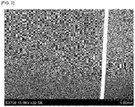
FIG. 1 is a SEM photograph of a surface of an opened article of high purity tin vacuum-packed via a Naflon sheet. -
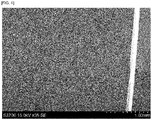
FIG. 2 is an SEM photograph of a surface of an opened article of high purity tin vacuum-packed directly by an Al vapor deposited polyethylene film without using a Naflon sheet. -
FIG. 3-1 is an SEM photograph enlarged near a deposit on a surface of an opened article of high purity tin vacuum-packed directly by an Al vapor deposited polyethylene film without using a Naflon sheet. -
FIG. 3-1 is an EDX photograph enlarged near a deposit on a surface of an opened article of high purity tin vacuum-packed directly by an Al vapor deposited polyethylene film without using a Naflon sheet. -
FIG.4 is an SEM photograph of a surface of high purity tin cut by a lathe. - Embodiments of the present invention will be described below in detail. The present invention is not limited to the embodiments described below.
- The vacuum-packed high purity metal article according to the present invention can be produced by vacuum-packing a high purity metal using a method including the steps of covering at least a part of a surface of the high purity metal with a fluorocarbon resin sheet; and vacuum-packing the high-purity metal with at least a part of the surface covered with the fluorocarbon resin sheet by a vacuum packing film.
- The vacuum packing according to the present invention can be suitably used for high purity metals that are susceptible to oxidation. Such high purity metals include, for example, high purity tin (Sn), bismuth (Bi) and copper (Cu). Preferably, high purity Sn may be used. It is important for such a high purity metal to reduce carbon impurities, in order to use the high purity metal as it is immediately after opening the vacuum packing, for example to melt the high purity metal immediately after opening the vacuum packing, without further performing washing operation such as etching, and then employ the high purity metal according to the present invention as a molten metal. The advantage of the present invention can be provided without no particular limitation as long as the purity of the high purity metal is of such a degree that the vacuum packing is used, for example, metals having a purity such as 2N (99%), 3N (99.9%), 4N (99.99%), 5N (99.999%), and 6N (99.9999%) may be used.
- The shape of the high purity metal is not particularly limited as long as it has a shape capable carrying out the operation of vacuum packing according to the present invention. Preferable shapes include, for example, shapes such as a substantially columnar shape, a columnar shape, a rectangular parallelepiped shape, and a cubic shape. Preferably, it may be substantially columnar. A person skilled in the art would be able to appropriately perform the vacuum packing depending on the shape of the high purity metal, by placing the fluorocarbon resin sheet along each shape to cover at least a part of the high purity metal, and vacuum-packing the high purity metal by a vacuum packing film.
- In a preferred embodiment, the high purity metal may have a surface roughness Ra, for example in a range of from 0.3 to 5.0 µm, and preferably in a range of from 0.3 to 3.3 µm, and more preferably in a range of from 0.5 to 3.0 µm. In the present invention, the surface roughness Ra can be determined as an arithmetic mean roughness. The surface roughness Ra is preferably smaller from the viewpoint of reducing the amount of carbon deposited, but if the surface roughness Ra is too small, scratches will tend to be generated during subsequent work, so that the appearance will be deteriorated.
- In the covering step with the fluorocarbon resin sheet, at least a part of the surface of the high purity metal is covered. The entire surface of the high purity metal may be covered. In order to effectively cover the high purity metal while maintaining the workability, a surface portion to which the vacuum packing film is strongly pressure-bonded during the vacuum packing is selected as at least a part of the surface to be covered, depending on the shape of the high purity metal. For example, when the high purity metal is substantially columnar, a curved surface on the side portion of the substantially columnar high purity metal is covered with the fluorocarbon resin sheet. In this case, if desired, the upper surface portion and/or the bottom surface portion of the substantially columnar high purity metal may be further covered, so that the entire surface of the substantially columnar high purity metal may be covered.
- In a preferred embodiment, examples of the fluorocarbon resin sheet include a polytetrafluoroethylene (PTFE) sheet, a tetrafluoroethylene-perfluoroalkyl vinyl ether copolymer, tetrafluoroethylene-hexafluoropropylene copolymer (tetra/hexa-fluorinated), a tetrafluoroethylene-ethylene copolymer, poly(vinylidene fluoride) (di-fluorinated), polychlorotrifluoroethylene (tri-fluorinated), chlorotrifluoroethylene-ethylene copolymer sheets and the like. Preferably, the polytetrafluoroethylene (PTFE) sheet includes a Teflon® sheet available from Du Pont and a Naflon® sheet available from NICHIAS Corporation. In a preferred embodiment, the thickness of the fluorocarbon resin sheet may be, for example in a range of from 0.01 to 6.0 mm, or in a range of from 0.05 to 5.0 mm, preferably in a range of from 0.02 to 4.0 mm, or in a range of from 0.05 to 3.0 mm. The thickness of the fluorocarbon resin sheet in such a range can achieve both rigidity for decreasing carbon deposits and flexibility for not breaking the vacuum packing film during the vacuum packing.
- The vacuum packing film that can be used includes, but not limited to, vacuum packing films conventionally used for vacuum packing of high purity metal. The vacuum packing film to be thus used includes films with reduced oxygen permeability (oxygen barrier films) and films with reduced water vapor permeability (water vapor barrier films). Example of such vacuum packing films include resin films having increased flexibility, laminated films having a metal layer(s) and/or a metal oxide layer (s) provided by vapor deposition or the like. Examples of resin films used for such laminated films include a polyethylene film, a nylon film, and a PET film. Examples of the metal of the metal layer provided by vapor deposition or the like include Al (aluminum) and Sn. Examples of the metal oxide of the metal oxide layer include Al2O3 (aluminum oxide) and SiO2 (silicon oxide). Preferably, an Al vapor deposited polyethylene film or a Sn vapor deposited polyethylene film may be used. The vacuum packing film that can be used may be a laminated film in which a layer(s) is/are further laminated on the above film, including, for example, laminated films in which polyethylene films, nylon films and/or PET films are further laminated on the surfaces of the metal layer and the metal oxide layer. Alternatively, a plurality of films (laminating films) can be appropriately stacked and vacuum packing can be carried out, if desired, in order to ensure protection during transportation, or further improve the water vapor barrier property, and the like.
- The vacuum packing using the vacuum packing film can be performed by a known means and under known conditions. Examples of a usable vacuum packing apparatus include KASHIWAGI type vacuum packaging machine (available from NPC Corporation), and GDP-400 (available from TAMURA SEAL CO., LTD.). In a preferred embodiment, the vacuum packing can be carried out under conditions with less particles.
- The vacuum packed high purity metal article (vacuum packed high purity tin article) according to the present invention can be used immediately after opening the vacuum packing without washing or the like. For example, the vacuum packed high purity metal article according to the present invention can be used as a molten metal for an ultrafine processing apparatus such as an LSI. The molten metal has significantly decreased carbon impurities, can suppress formation of undesirable particles, and does not generate clogging of fine flow paths.
- While Examples and Comparative Examples will be described below, these are merely for better understanding of the invention. The present invention is not intended to be limited by Examples or Comparative Examples.
- Commercially available bulk tin having purity 4N (99.99% by mass; excluding carbon, nitrogen, oxygen, hydrogen) was prepared.
- This was cut into a columnar shape having a diameter of 50, a length of 50 mm and a surface roughness Ra of 3.0 µm by means of a lathe.
- The column of tin was packed by a Naflon sheet having a thickness of 0.3 mm (available from NICHIAS Corporation) and further sandwiched by two Al vapor deposited polyethylene films (trade name DNP Technopack, available from Dai Nippon Printing Co., Ltd.) (a thickness of deposited Al of 12 µm, and a thickness of polyethylene of 80 µm) from the up and down directions, while directing the polyethylene surfaces to the inner side. Subsequently, the end portion was heated and sealed by a sealer to form a bag to be wrapped, and the vacuum packing was then carried out by heating and sealing the opening of the bag under vacuum suction at about -64 kPa. The KASHIWAGI type vacuum packaging machine was used as a vacuum packing machine.
- After leaving the vacuum packed article to stand for 3 hours, it was opened and the curved surface on the side of the columnar object was observed by SEM/EDX. The results are shown in
FIG. 1 . - As shown in
FIG. 1 , the SEM (Scanning Electron Microscopy) and EDX (Energy Dispersive X-ray Spectroscopy) observations demonstrated that there was no adhesion of carbon in the opened article of high purity tin vacuum-packed via the Naflon sheet. The results are summarized in Table 1. - Experiments were carried out by the same method as that of Example 1, with the exception that the thickness of the Naflon sheet in Example 1 was changed. The results were summarized in Table 1 as Example 2 (a thickness of the Naflon sheet of 0.05 mm) and Example 3 (a thickness of the Naflon sheet of 3 mm).
- In Comparative Example 1, the vacuum packing was carried out by the same method as of Example 1, but without using the Naflon sheet, that is, directly by an Al vapor deposited polyethylene film, and the vacuum packed article was left to stand for 3 hours and then opened, and the curved surface on the side of the columnar object was observed by SEM/EDX. The results are shown in
FIGS. 2 ,3-1 and3-2 . These results are also summarized in Table 1.[Table 1] Example 1 Example 2 Example 3 Comparative Example 1 Presence or absence of Naflon sheet Present Present Present Absent Thickness of Naflon Sheet (mm) 0.3 0.05 3 ----- Carbon Adhesion on Tin Surface Absent Absent Absent Present -
FIG. 2 is a photograph observed by SEM (scanning electron microscope) under the same conditions as those ofFIG. 1 (Example 1). InFIG. 2 , an increased number of vertical stripes running from the top to the bottom of the photograph are observed, which would be vertical stripes generated due to the lathe processing and would be linearly continuous projections. In the vertical stripes near the center in the left and right direction of the photograph among these vertical stripes, the deposits each having a certain lateral width spreading like a stain are observed along the vertical strips. These deposits appear to be near the top part when assuming that each strip is a continuous linear projection. The massive deposits having different shapes from those deposits along the vertical stripes are also observed near the center of the photograph.FIG. 3-1 is an enlarged SEM photograph of the vicinity of the former deposit, in which the deposit is clearly observed.FIG. 3-2 is an EDX photograph of the same field of view as that ofFIG. 3-1 , in which it is clearly observed that the deposit is a carbon-containing deposit. - As a result of studying candidates which may be the origin of such carbon deposits, the present inventors have concluded that the deposits are derived from the polyethylene film adhering onto the tin surface. The surface of high purity tin is sufficiently smooth when macroscopically observed, but the surface of high purity tin forms peaks and valleys which will be derived from the cutting work and the like when microscopically observed. The present inventors believe that the polyethylene film is scraped by the peaks and valleys, and fine fragments adhere due to pressure bonding during vacuum packing.
-
FIG. 4 is a photograph in which the surface of high purity tin cut by the lathe is observed by SEM (scanning electron microscope) under the same conditions as those ofFIG. 1 (Example 1). As shown inFIG. 4 , the surface of high purity tin appears to be smooth when macroscopically observed, but the surface forms peaks and valleys when microscopically observed. - The microscopic peaks and valleys on the surface of high purity tin may be probably in the form of blades, and they would be generated when the flexible polyethylene sheet is pressure-bonded onto the peaks and valleys on the tin surface and scratches the tin surface during vacuum packing. In contrast to polyethylene, it is believed that since the Naflon sheet is rigid and has a good sliding property, it would not adhere to the tin surface.
- Further, the vacuum packing under the same conditions as those of Example 1 was carried out using a Naflon sheet having a thickness of 10 mm. As a result, the Al vapor deposited polyethylene (a thickness of deposited Al of 12 µm; a thickness of polyethylene of 80 µm) was broken by the projections at the end of the Naflon sheet during processing after the vacuum packing. Therefore, although there is no upper limit on the thickness of the usable Naflon sheet in terms of reduction of carbon deposits, the thickness of the Naflon sheet is preferably selected so as to be a thickness to such an extent that flexibility enough not to bring about any breakage in the outer packing material due to the projections at the end portion of the Naflon sheet can be maintained, depending on the flexibility of the packing material such as the Al vapor deposited polyethylene used on the outer side of the Naflon sheet.
- According to the present invention, a high purity metal product (a high purity tin product) containing no undesirable carbon impurities can be obtained. The present invention is an industrially useful invention.
Claims (14)
- A vacuum-packed high purity metal article comprising a vacuum-packed high purity metal,
wherein at least a part of a surface of the high purity metal is covered with a fluorocarbon resin sheet; and
wherein the high purity metal with at least a part of the surface covered with the fluorocarbon resin sheet is vacuum-packed by a vacuum packing film. - The vacuum-packed high purity metal article according to claim 1, wherein the fluorocarbon resin sheet comprises a polytetrafluoroethylene (PTFE) sheet.
- The vacuum-packed high purity metal article according to claim 1 or 2, wherein the fluorocarbon resin sheet has a thickness of from 0.05 to 5.0 mm.
- The vacuum-packed high purity metal article according to any one of claims 1 to 3, wherein the vacuum packing film comprises a laminated film having at least one metal vapor deposited layer or at least one metal oxide vapor deposited layer, and wherein the at least one metal vapor deposited layer or the at least one metal oxide vapor deposited layer is vacuum-packed without being brought into contact with the high purity metal.
- The vacuum-packed high purity metal article according to any one of claims 1 to 4,
wherein the vacuum packing film comprises an Al vapor deposited polyethylene film; and
wherein the Al vapor deposited layer is vacuum-packed without being brought into contact with the high purity metal. - The vacuum-packed high purity metal article according to any one of claims 1 to 5, wherein the high purity metal has a substantially columnar shape.
- The vacuum-packed high purity metal article according to any one of claims 1 to 6, wherein the high purity metal has a surface roughness Ra in a range of from 0.3 to 5.0 µm.
- The vacuum-packed high purity metal article according to any one of claims 1 to 7, wherein the high purity metal comprises high purity tin.
- The vacuum-packed high purity metal article according to any one of claims 1 to 8,
wherein the high purity metal has a substantially columnar shape;
wherein a curved surface on a side portion of the substantially columnar shaped high purity metal is covered with a fluorocarbon resin sheet; and
wherein the substantially columnar shaped high purity metal with the curved surface on the side portion covered with the fluorocarbon resin sheet is vacuum-packed by a vacuum packing film. - A method for vacuum-packing a high purity metal, the method comprising the steps of:covering at least a part of a surface of the high purity metal with a fluorocarbon resin sheet; andvacuum-packing the high-purity metal with at least a part of the surface covered with the fluorocarbon resin sheet by a vacuum packing film.
- A method for producing a vacuum-packed high purity metal article comprising a vacuum-packed high purity metal, the method comprising the steps of:covering at least a part of a surface of the high purity metal with a fluorocarbon resin sheet; andvacuum-packing the high-purity metal with at least a part of the surface covered with the fluorocarbon resin sheet by a vacuum packing film.
- The method according to claim 10 or 11,
wherein the vacuum packing film comprises a laminated film having at least one metal vapor deposited layer or at least one metal oxide vapor deposited layer; and
wherein the at least one metal vapor deposited layer or the at least one metal oxide vapor deposited layer is vacuum-packed without being brought into contact with the high purity metal. - The method according to any one of claims 10 to 12,
wherein the vacuum packing film comprises an Al vapor deposited polyethylene film; and
wherein the Al vapor deposited layer is vacuum-packed without being brought into contact with the high purity metal. - The method according to any one of claims 10 to 13,
wherein the step of covering at least a part of the surface of the high purity metal with the fluorocarbon resin sheet comprises covering a curved surface on a side portion of a substantially columnar shaped high purity metal with a fluorocarbon resin sheet; and
wherein the step of vacuum-packing the high-purity metal with at least a part of the surface covered with the fluorocarbon resin sheet by the vacuum packing film comprises vacuum-packing the substantially columnar shaped high purity metal with the curved surface on the side portion covered with the fluorocarbon resin sheet, by the vacuum packing film.
Applications Claiming Priority (2)
| Application Number | Priority Date | Filing Date | Title |
|---|---|---|---|
| JP2016031308 | 2016-02-22 | ||
| PCT/JP2017/005973 WO2017145947A1 (en) | 2016-02-22 | 2017-02-17 | Method for vacuum packing high-purity tin and vacuum-packed high-purity tin |
Publications (3)
| Publication Number | Publication Date |
|---|---|
| EP3421389A1 true EP3421389A1 (en) | 2019-01-02 |
| EP3421389A4 EP3421389A4 (en) | 2019-01-09 |
| EP3421389B1 EP3421389B1 (en) | 2019-08-21 |
Family
ID=59685111
Family Applications (1)
| Application Number | Title | Priority Date | Filing Date |
|---|---|---|---|
| EP17756386.3A Active EP3421389B1 (en) | 2016-02-22 | 2017-02-17 | Method for vacuum packing high-purity tin and vacuum-packed high-purity tin |
Country Status (6)
| Country | Link |
|---|---|
| US (1) | US10781024B2 (en) |
| EP (1) | EP3421389B1 (en) |
| JP (1) | JP6850786B2 (en) |
| KR (1) | KR102076925B1 (en) |
| TW (1) | TWI634051B (en) |
| WO (1) | WO2017145947A1 (en) |
Cited By (1)
| Publication number | Priority date | Publication date | Assignee | Title |
|---|---|---|---|---|
| EP3872200A4 (en) * | 2019-03-04 | 2021-12-29 | JX Nippon Mining & Metals Corporation | Oxidation-resistant metallic tin |
Families Citing this family (1)
| Publication number | Priority date | Publication date | Assignee | Title |
|---|---|---|---|---|
| JP7782130B2 (en) * | 2021-02-02 | 2025-12-09 | 三菱マテリアル株式会社 | Package of electrode plate for plasma etcher and packaging method for the package of electrode plate for plasma etcher |
Family Cites Families (16)
| Publication number | Priority date | Publication date | Assignee | Title |
|---|---|---|---|---|
| US3522077A (en) * | 1967-08-04 | 1970-07-28 | Westinghouse Electric Corp | Inert plastic package for liquid reagent |
| FR2492342A1 (en) * | 1980-10-20 | 1982-04-23 | Conditionn Ste Gle Entreprise | BAG FOR VACUUM INSULATION AND GAS IMPREGNABLE PACKAGING |
| DE3524846A1 (en) * | 1985-07-12 | 1987-01-15 | Hoechst Ag | PACKING FOR DRY RESISTANT MATERIAL |
| JPH01199877A (en) * | 1988-02-02 | 1989-08-11 | Mitsui Eng & Shipbuild Co Ltd | Package of highly pure members |
| US4896813A (en) * | 1989-04-03 | 1990-01-30 | Toyo Kohan Co., Ltd. | Method and apparatus for cold rolling clad sheet |
| US5846645A (en) | 1995-03-03 | 1998-12-08 | Asahi Glass Company Ltd. | Fluorocarbon resin-coated product |
| US6000198A (en) * | 1998-04-07 | 1999-12-14 | Calgon Carbon Corporation | Method and package for packaging contents at reduced pressures |
| JP2001240959A (en) | 1999-12-22 | 2001-09-04 | Mitsui Mining & Smelting Co Ltd | Packaged high-purity target |
| TW546396B (en) * | 1999-12-22 | 2003-08-11 | Mitsui Mining & Smelting Co | Packed high purity target |
| JP2004059154A (en) * | 2002-06-04 | 2004-02-26 | Nippon Electric Glass Co Ltd | Sealing material packed body and method of packing sealing material |
| JP2005298036A (en) * | 2004-04-15 | 2005-10-27 | Toshiba Corp | Anti-rust bag for packaging metal parts |
| AU2008238998B2 (en) * | 2007-04-11 | 2011-02-24 | Nippon Steel Corporation | Hot-dip metal coated high-strength steel sheet for press working excellent in low-temperature toughness and process for production thereof |
| US9062828B2 (en) | 2010-10-27 | 2015-06-23 | Advanced Technology Materials, Inc. | Liner-based assembly for removing impurities |
| JP5583777B2 (en) * | 2011-03-01 | 2014-09-03 | Jx日鉱日石金属株式会社 | Method for storing metallic lanthanum target and vacuum sealed metallic lanthanum target |
| CN104326109A (en) * | 2014-08-29 | 2015-02-04 | 淮南新光神光纤线缆有限公司 | Anti-oxidizing package method for silver plated copper wire |
| CN105173267A (en) * | 2015-06-17 | 2015-12-23 | 中天合金技术有限公司 | Copper strip anti-oxidation packaging method |
-
2017
- 2017-02-16 TW TW106105070A patent/TWI634051B/en active
- 2017-02-17 KR KR1020187020367A patent/KR102076925B1/en active Active
- 2017-02-17 EP EP17756386.3A patent/EP3421389B1/en active Active
- 2017-02-17 US US16/078,139 patent/US10781024B2/en active Active
- 2017-02-17 WO PCT/JP2017/005973 patent/WO2017145947A1/en not_active Ceased
- 2017-02-17 JP JP2018501643A patent/JP6850786B2/en active Active
Cited By (2)
| Publication number | Priority date | Publication date | Assignee | Title |
|---|---|---|---|---|
| EP3872200A4 (en) * | 2019-03-04 | 2021-12-29 | JX Nippon Mining & Metals Corporation | Oxidation-resistant metallic tin |
| US12129529B2 (en) | 2019-03-04 | 2024-10-29 | Jx Advanced Metals Corporation | Oxidation-resistant metallic tin |
Also Published As
| Publication number | Publication date |
|---|---|
| WO2017145947A1 (en) | 2017-08-31 |
| KR102076925B1 (en) | 2020-02-12 |
| US20190055077A1 (en) | 2019-02-21 |
| TW201733862A (en) | 2017-10-01 |
| KR20180095641A (en) | 2018-08-27 |
| JPWO2017145947A1 (en) | 2018-12-20 |
| JP6850786B2 (en) | 2021-03-31 |
| TWI634051B (en) | 2018-09-01 |
| US10781024B2 (en) | 2020-09-22 |
| EP3421389A4 (en) | 2019-01-09 |
| EP3421389B1 (en) | 2019-08-21 |
Similar Documents
| Publication | Publication Date | Title |
|---|---|---|
| JP3099829B2 (en) | Manufacturing method of capsule for isotropic pressure treatment | |
| EP3421389B1 (en) | Method for vacuum packing high-purity tin and vacuum-packed high-purity tin | |
| EP3127647A1 (en) | Method for producing metal laminate material | |
| CN102764936B (en) | Big-thickness slab manufacturing technique | |
| US10047433B2 (en) | Tungsten sintered compact sputtering target and tungsten film formed using same target | |
| CN106392270B (en) | With the method for electric arc increasing material manufacturing aluminium alloy multilayer single track closing structure part | |
| US20150176118A1 (en) | Web substrate roll-forming apparatus and web substrate roll | |
| JP4856371B2 (en) | Laminated body for packaging, packaging bag body using the same, and packaging body for electronic material products | |
| CN110325364A (en) | Anti-fog sealing composition and coextruded multilayer polyester film comprising the same | |
| KR102660618B1 (en) | Methods and process flows for diffusion bonding and forming metallic sheets | |
| CN107424703A (en) | Grain boundary decision legal system makees the heavy rare earth attachment technique of sintered NdFeB permanent magnet | |
| KR102425203B1 (en) | Sputtering target and packaging method thereof | |
| KR102001045B1 (en) | Preparation method of sputtering target and sputtering target prepared thereby | |
| CN104722594A (en) | Manufacturing method of large-width eutectic structure aluminium-based brazing filler metal slices | |
| TWI787236B (en) | Method for processing sputtering target, apparatus for processing sputtering target, sputtering target and method for manufacturing sputtering target product | |
| US20200180840A1 (en) | Vacuum-packaged product of high-purity metal and method for producing vacuum-packaged product | |
| CN103173718B (en) | Aluminum oxide film containing Ta | |
| CN111217024A (en) | Packaging structure of sputtering target and packaging method of sputtering target | |
| WO2015064810A1 (en) | Method for regenerating spent sputtering target, and sputtering target regenerated thereby | |
| JPS6250253B2 (en) | ||
| KR102713110B1 (en) | Edge cleaner system for sheet, Cleaning method of sheet using the same and Manufacturing method of encapsulation member for organic electronic device using the same | |
| JPS6247651B2 (en) | ||
| JP6770842B2 (en) | Manufacturing method, manufacturing equipment, and laminated sheet molded product of laminated sheet molded product | |
| TWI589703B (en) | Titanium composite material and hot processing titanium material |
Legal Events
| Date | Code | Title | Description |
|---|---|---|---|
| STAA | Information on the status of an ep patent application or granted ep patent |
Free format text: STATUS: THE INTERNATIONAL PUBLICATION HAS BEEN MADE |
|
| PUAI | Public reference made under article 153(3) epc to a published international application that has entered the european phase |
Free format text: ORIGINAL CODE: 0009012 |
|
| STAA | Information on the status of an ep patent application or granted ep patent |
Free format text: STATUS: REQUEST FOR EXAMINATION WAS MADE |
|
| 17P | Request for examination filed |
Effective date: 20180904 |
|
| AK | Designated contracting states |
Kind code of ref document: A1 Designated state(s): AL AT BE BG CH CY CZ DE DK EE ES FI FR GB GR HR HU IE IS IT LI LT LU LV MC MK MT NL NO PL PT RO RS SE SI SK SM TR |
|
| AX | Request for extension of the european patent |
Extension state: BA ME |
|
| A4 | Supplementary search report drawn up and despatched |
Effective date: 20181210 |
|
| RIC1 | Information provided on ipc code assigned before grant |
Ipc: B65D 81/20 20060101AFI20181204BHEP Ipc: B65D 85/50 20060101ALI20181204BHEP |
|
| GRAP | Despatch of communication of intention to grant a patent |
Free format text: ORIGINAL CODE: EPIDOSNIGR1 |
|
| STAA | Information on the status of an ep patent application or granted ep patent |
Free format text: STATUS: GRANT OF PATENT IS INTENDED |
|
| DAV | Request for validation of the european patent (deleted) | ||
| DAX | Request for extension of the european patent (deleted) | ||
| INTG | Intention to grant announced |
Effective date: 20190402 |
|
| GRAJ | Information related to disapproval of communication of intention to grant by the applicant or resumption of examination proceedings by the epo deleted |
Free format text: ORIGINAL CODE: EPIDOSDIGR1 |
|
| STAA | Information on the status of an ep patent application or granted ep patent |
Free format text: STATUS: REQUEST FOR EXAMINATION WAS MADE |
|
| GRAR | Information related to intention to grant a patent recorded |
Free format text: ORIGINAL CODE: EPIDOSNIGR71 |
|
| GRAS | Grant fee paid |
Free format text: ORIGINAL CODE: EPIDOSNIGR3 |
|
| STAA | Information on the status of an ep patent application or granted ep patent |
Free format text: STATUS: GRANT OF PATENT IS INTENDED |
|
| INTC | Intention to grant announced (deleted) | ||
| GRAA | (expected) grant |
Free format text: ORIGINAL CODE: 0009210 |
|
| STAA | Information on the status of an ep patent application or granted ep patent |
Free format text: STATUS: THE PATENT HAS BEEN GRANTED |
|
| AK | Designated contracting states |
Kind code of ref document: B1 Designated state(s): AL AT BE BG CH CY CZ DE DK EE ES FI FR GB GR HR HU IE IS IT LI LT LU LV MC MK MT NL NO PL PT RO RS SE SI SK SM TR |
|
| INTG | Intention to grant announced |
Effective date: 20190716 |
|
| REG | Reference to a national code |
Ref country code: GB Ref legal event code: FG4D |
|
| REG | Reference to a national code |
Ref country code: CH Ref legal event code: EP |
|
| REG | Reference to a national code |
Ref country code: DE Ref legal event code: R096 Ref document number: 602017006394 Country of ref document: DE |
|
| REG | Reference to a national code |
Ref country code: AT Ref legal event code: REF Ref document number: 1169502 Country of ref document: AT Kind code of ref document: T Effective date: 20190915 |
|
| REG | Reference to a national code |
Ref country code: IE Ref legal event code: FG4D |
|
| REG | Reference to a national code |
Ref country code: NL Ref legal event code: FP |
|
| REG | Reference to a national code |
Ref country code: LT Ref legal event code: MG4D |
|
| PG25 | Lapsed in a contracting state [announced via postgrant information from national office to epo] |
Ref country code: BG Free format text: LAPSE BECAUSE OF FAILURE TO SUBMIT A TRANSLATION OF THE DESCRIPTION OR TO PAY THE FEE WITHIN THE PRESCRIBED TIME-LIMIT Effective date: 20191121 Ref country code: NO Free format text: LAPSE BECAUSE OF FAILURE TO SUBMIT A TRANSLATION OF THE DESCRIPTION OR TO PAY THE FEE WITHIN THE PRESCRIBED TIME-LIMIT Effective date: 20191121 Ref country code: LT Free format text: LAPSE BECAUSE OF FAILURE TO SUBMIT A TRANSLATION OF THE DESCRIPTION OR TO PAY THE FEE WITHIN THE PRESCRIBED TIME-LIMIT Effective date: 20190821 Ref country code: FI Free format text: LAPSE BECAUSE OF FAILURE TO SUBMIT A TRANSLATION OF THE DESCRIPTION OR TO PAY THE FEE WITHIN THE PRESCRIBED TIME-LIMIT Effective date: 20190821 Ref country code: HR Free format text: LAPSE BECAUSE OF FAILURE TO SUBMIT A TRANSLATION OF THE DESCRIPTION OR TO PAY THE FEE WITHIN THE PRESCRIBED TIME-LIMIT Effective date: 20190821 Ref country code: PT Free format text: LAPSE BECAUSE OF FAILURE TO SUBMIT A TRANSLATION OF THE DESCRIPTION OR TO PAY THE FEE WITHIN THE PRESCRIBED TIME-LIMIT Effective date: 20191223 Ref country code: SE Free format text: LAPSE BECAUSE OF FAILURE TO SUBMIT A TRANSLATION OF THE DESCRIPTION OR TO PAY THE FEE WITHIN THE PRESCRIBED TIME-LIMIT Effective date: 20190821 |
|
| PG25 | Lapsed in a contracting state [announced via postgrant information from national office to epo] |
Ref country code: GR Free format text: LAPSE BECAUSE OF FAILURE TO SUBMIT A TRANSLATION OF THE DESCRIPTION OR TO PAY THE FEE WITHIN THE PRESCRIBED TIME-LIMIT Effective date: 20191122 Ref country code: ES Free format text: LAPSE BECAUSE OF FAILURE TO SUBMIT A TRANSLATION OF THE DESCRIPTION OR TO PAY THE FEE WITHIN THE PRESCRIBED TIME-LIMIT Effective date: 20190821 Ref country code: LV Free format text: LAPSE BECAUSE OF FAILURE TO SUBMIT A TRANSLATION OF THE DESCRIPTION OR TO PAY THE FEE WITHIN THE PRESCRIBED TIME-LIMIT Effective date: 20190821 Ref country code: AL Free format text: LAPSE BECAUSE OF FAILURE TO SUBMIT A TRANSLATION OF THE DESCRIPTION OR TO PAY THE FEE WITHIN THE PRESCRIBED TIME-LIMIT Effective date: 20190821 Ref country code: RS Free format text: LAPSE BECAUSE OF FAILURE TO SUBMIT A TRANSLATION OF THE DESCRIPTION OR TO PAY THE FEE WITHIN THE PRESCRIBED TIME-LIMIT Effective date: 20190821 Ref country code: IS Free format text: LAPSE BECAUSE OF FAILURE TO SUBMIT A TRANSLATION OF THE DESCRIPTION OR TO PAY THE FEE WITHIN THE PRESCRIBED TIME-LIMIT Effective date: 20191221 |
|
| REG | Reference to a national code |
Ref country code: AT Ref legal event code: MK05 Ref document number: 1169502 Country of ref document: AT Kind code of ref document: T Effective date: 20190821 |
|
| PG25 | Lapsed in a contracting state [announced via postgrant information from national office to epo] |
Ref country code: TR Free format text: LAPSE BECAUSE OF FAILURE TO SUBMIT A TRANSLATION OF THE DESCRIPTION OR TO PAY THE FEE WITHIN THE PRESCRIBED TIME-LIMIT Effective date: 20190821 |
|
| PG25 | Lapsed in a contracting state [announced via postgrant information from national office to epo] |
Ref country code: AT Free format text: LAPSE BECAUSE OF FAILURE TO SUBMIT A TRANSLATION OF THE DESCRIPTION OR TO PAY THE FEE WITHIN THE PRESCRIBED TIME-LIMIT Effective date: 20190821 Ref country code: DK Free format text: LAPSE BECAUSE OF FAILURE TO SUBMIT A TRANSLATION OF THE DESCRIPTION OR TO PAY THE FEE WITHIN THE PRESCRIBED TIME-LIMIT Effective date: 20190821 Ref country code: IT Free format text: LAPSE BECAUSE OF FAILURE TO SUBMIT A TRANSLATION OF THE DESCRIPTION OR TO PAY THE FEE WITHIN THE PRESCRIBED TIME-LIMIT Effective date: 20190821 Ref country code: PL Free format text: LAPSE BECAUSE OF FAILURE TO SUBMIT A TRANSLATION OF THE DESCRIPTION OR TO PAY THE FEE WITHIN THE PRESCRIBED TIME-LIMIT Effective date: 20190821 Ref country code: EE Free format text: LAPSE BECAUSE OF FAILURE TO SUBMIT A TRANSLATION OF THE DESCRIPTION OR TO PAY THE FEE WITHIN THE PRESCRIBED TIME-LIMIT Effective date: 20190821 Ref country code: RO Free format text: LAPSE BECAUSE OF FAILURE TO SUBMIT A TRANSLATION OF THE DESCRIPTION OR TO PAY THE FEE WITHIN THE PRESCRIBED TIME-LIMIT Effective date: 20190821 |
|
| PG25 | Lapsed in a contracting state [announced via postgrant information from national office to epo] |
Ref country code: IS Free format text: LAPSE BECAUSE OF FAILURE TO SUBMIT A TRANSLATION OF THE DESCRIPTION OR TO PAY THE FEE WITHIN THE PRESCRIBED TIME-LIMIT Effective date: 20200224 Ref country code: SK Free format text: LAPSE BECAUSE OF FAILURE TO SUBMIT A TRANSLATION OF THE DESCRIPTION OR TO PAY THE FEE WITHIN THE PRESCRIBED TIME-LIMIT Effective date: 20190821 Ref country code: CZ Free format text: LAPSE BECAUSE OF FAILURE TO SUBMIT A TRANSLATION OF THE DESCRIPTION OR TO PAY THE FEE WITHIN THE PRESCRIBED TIME-LIMIT Effective date: 20190821 Ref country code: SM Free format text: LAPSE BECAUSE OF FAILURE TO SUBMIT A TRANSLATION OF THE DESCRIPTION OR TO PAY THE FEE WITHIN THE PRESCRIBED TIME-LIMIT Effective date: 20190821 |
|
| REG | Reference to a national code |
Ref country code: DE Ref legal event code: R097 Ref document number: 602017006394 Country of ref document: DE |
|
| PLBE | No opposition filed within time limit |
Free format text: ORIGINAL CODE: 0009261 |
|
| STAA | Information on the status of an ep patent application or granted ep patent |
Free format text: STATUS: NO OPPOSITION FILED WITHIN TIME LIMIT |
|
| PG2D | Information on lapse in contracting state deleted |
Ref country code: IS |
|
| 26N | No opposition filed |
Effective date: 20200603 |
|
| REG | Reference to a national code |
Ref country code: DE Ref legal event code: R119 Ref document number: 602017006394 Country of ref document: DE |
|
| REG | Reference to a national code |
Ref country code: CH Ref legal event code: PL |
|
| REG | Reference to a national code |
Ref country code: BE Ref legal event code: MM Effective date: 20200229 |
|
| PG25 | Lapsed in a contracting state [announced via postgrant information from national office to epo] |
Ref country code: MC Free format text: LAPSE BECAUSE OF FAILURE TO SUBMIT A TRANSLATION OF THE DESCRIPTION OR TO PAY THE FEE WITHIN THE PRESCRIBED TIME-LIMIT Effective date: 20190821 Ref country code: LU Free format text: LAPSE BECAUSE OF NON-PAYMENT OF DUE FEES Effective date: 20200217 |
|
| PG25 | Lapsed in a contracting state [announced via postgrant information from national office to epo] |
Ref country code: LI Free format text: LAPSE BECAUSE OF NON-PAYMENT OF DUE FEES Effective date: 20200229 Ref country code: CH Free format text: LAPSE BECAUSE OF NON-PAYMENT OF DUE FEES Effective date: 20200229 |
|
| PG25 | Lapsed in a contracting state [announced via postgrant information from national office to epo] |
Ref country code: IE Free format text: LAPSE BECAUSE OF NON-PAYMENT OF DUE FEES Effective date: 20200217 Ref country code: FR Free format text: LAPSE BECAUSE OF NON-PAYMENT OF DUE FEES Effective date: 20200229 Ref country code: DE Free format text: LAPSE BECAUSE OF NON-PAYMENT OF DUE FEES Effective date: 20200901 |
|
| PG25 | Lapsed in a contracting state [announced via postgrant information from national office to epo] |
Ref country code: BE Free format text: LAPSE BECAUSE OF NON-PAYMENT OF DUE FEES Effective date: 20200229 |
|
| GBPC | Gb: european patent ceased through non-payment of renewal fee |
Effective date: 20210217 |
|
| PG25 | Lapsed in a contracting state [announced via postgrant information from national office to epo] |
Ref country code: GB Free format text: LAPSE BECAUSE OF NON-PAYMENT OF DUE FEES Effective date: 20210217 |
|
| PG25 | Lapsed in a contracting state [announced via postgrant information from national office to epo] |
Ref country code: MT Free format text: LAPSE BECAUSE OF FAILURE TO SUBMIT A TRANSLATION OF THE DESCRIPTION OR TO PAY THE FEE WITHIN THE PRESCRIBED TIME-LIMIT Effective date: 20190821 Ref country code: CY Free format text: LAPSE BECAUSE OF FAILURE TO SUBMIT A TRANSLATION OF THE DESCRIPTION OR TO PAY THE FEE WITHIN THE PRESCRIBED TIME-LIMIT Effective date: 20190821 |
|
| PG25 | Lapsed in a contracting state [announced via postgrant information from national office to epo] |
Ref country code: MK Free format text: LAPSE BECAUSE OF FAILURE TO SUBMIT A TRANSLATION OF THE DESCRIPTION OR TO PAY THE FEE WITHIN THE PRESCRIBED TIME-LIMIT Effective date: 20190821 |
|
| PG25 | Lapsed in a contracting state [announced via postgrant information from national office to epo] |
Ref country code: SI Free format text: LAPSE BECAUSE OF FAILURE TO SUBMIT A TRANSLATION OF THE DESCRIPTION OR TO PAY THE FEE WITHIN THE PRESCRIBED TIME-LIMIT Effective date: 20190821 |
|
| PGFP | Annual fee paid to national office [announced via postgrant information from national office to epo] |
Ref country code: NL Payment date: 20260106 Year of fee payment: 10 |