EP3421300B1 - Control unit for vehicle - Google Patents
Control unit for vehicle Download PDFInfo
- Publication number
- EP3421300B1 EP3421300B1 EP17756187.5A EP17756187A EP3421300B1 EP 3421300 B1 EP3421300 B1 EP 3421300B1 EP 17756187 A EP17756187 A EP 17756187A EP 3421300 B1 EP3421300 B1 EP 3421300B1
- Authority
- EP
- European Patent Office
- Prior art keywords
- pressing
- threshold value
- touch sensor
- controller
- data based
- Prior art date
- Legal status (The legal status is an assumption and is not a legal conclusion. Google has not performed a legal analysis and makes no representation as to the accuracy of the status listed.)
- Active
Links
Images




Classifications
-
- G—PHYSICS
- G06—COMPUTING OR CALCULATING; COUNTING
- G06F—ELECTRIC DIGITAL DATA PROCESSING
- G06F3/00—Input arrangements for transferring data to be processed into a form capable of being handled by the computer; Output arrangements for transferring data from processing unit to output unit, e.g. interface arrangements
- G06F3/01—Input arrangements or combined input and output arrangements for interaction between user and computer
- G06F3/048—Interaction techniques based on graphical user interfaces [GUI]
- G06F3/0487—Interaction techniques based on graphical user interfaces [GUI] using specific features provided by the input device, e.g. functions controlled by the rotation of a mouse with dual sensing arrangements, or of the nature of the input device, e.g. tap gestures based on pressure sensed by a digitiser
- G06F3/0488—Interaction techniques based on graphical user interfaces [GUI] using specific features provided by the input device, e.g. functions controlled by the rotation of a mouse with dual sensing arrangements, or of the nature of the input device, e.g. tap gestures based on pressure sensed by a digitiser using a touch-screen or digitiser, e.g. input of commands through traced gestures
- G06F3/04886—Interaction techniques based on graphical user interfaces [GUI] using specific features provided by the input device, e.g. functions controlled by the rotation of a mouse with dual sensing arrangements, or of the nature of the input device, e.g. tap gestures based on pressure sensed by a digitiser using a touch-screen or digitiser, e.g. input of commands through traced gestures by partitioning the display area of the touch-screen or the surface of the digitising tablet into independently controllable areas, e.g. virtual keyboards or menus
-
- G—PHYSICS
- G06—COMPUTING OR CALCULATING; COUNTING
- G06F—ELECTRIC DIGITAL DATA PROCESSING
- G06F3/00—Input arrangements for transferring data to be processed into a form capable of being handled by the computer; Output arrangements for transferring data from processing unit to output unit, e.g. interface arrangements
- G06F3/01—Input arrangements or combined input and output arrangements for interaction between user and computer
- G06F3/048—Interaction techniques based on graphical user interfaces [GUI]
- G06F3/0481—Interaction techniques based on graphical user interfaces [GUI] based on specific properties of the displayed interaction object or a metaphor-based environment, e.g. interaction with desktop elements like windows or icons, or assisted by a cursor's changing behaviour or appearance
- G06F3/0482—Interaction with lists of selectable items, e.g. menus
-
- B—PERFORMING OPERATIONS; TRANSPORTING
- B60—VEHICLES IN GENERAL
- B60R—VEHICLES, VEHICLE FITTINGS, OR VEHICLE PARTS, NOT OTHERWISE PROVIDED FOR
- B60R11/00—Arrangements for holding or mounting articles, not otherwise provided for
- B60R11/02—Arrangements for holding or mounting articles, not otherwise provided for for radio sets, television sets, telephones, or the like; Arrangement of controls thereof
-
- B—PERFORMING OPERATIONS; TRANSPORTING
- B60—VEHICLES IN GENERAL
- B60R—VEHICLES, VEHICLE FITTINGS, OR VEHICLE PARTS, NOT OTHERWISE PROVIDED FOR
- B60R16/00—Electric or fluid circuits specially adapted for vehicles and not otherwise provided for; Arrangement of elements of electric or fluid circuits specially adapted for vehicles and not otherwise provided for
- B60R16/02—Electric or fluid circuits specially adapted for vehicles and not otherwise provided for; Arrangement of elements of electric or fluid circuits specially adapted for vehicles and not otherwise provided for electric constitutive elements
-
- G—PHYSICS
- G06—COMPUTING OR CALCULATING; COUNTING
- G06F—ELECTRIC DIGITAL DATA PROCESSING
- G06F3/00—Input arrangements for transferring data to be processed into a form capable of being handled by the computer; Output arrangements for transferring data from processing unit to output unit, e.g. interface arrangements
- G06F3/01—Input arrangements or combined input and output arrangements for interaction between user and computer
- G06F3/03—Arrangements for converting the position or the displacement of a member into a coded form
- G06F3/033—Pointing devices displaced or positioned by the user, e.g. mice, trackballs, pens or joysticks; Accessories therefor
- G06F3/0354—Pointing devices displaced or positioned by the user, e.g. mice, trackballs, pens or joysticks; Accessories therefor with detection of two-dimensional [2D] relative movements between the device, or an operating part thereof, and a plane or surface, e.g. 2D mice, trackballs, pens or pucks
- G06F3/03547—Touch pads, in which fingers can move on a surface
-
- G—PHYSICS
- G06—COMPUTING OR CALCULATING; COUNTING
- G06F—ELECTRIC DIGITAL DATA PROCESSING
- G06F3/00—Input arrangements for transferring data to be processed into a form capable of being handled by the computer; Output arrangements for transferring data from processing unit to output unit, e.g. interface arrangements
- G06F3/01—Input arrangements or combined input and output arrangements for interaction between user and computer
- G06F3/048—Interaction techniques based on graphical user interfaces [GUI]
- G06F3/0484—Interaction techniques based on graphical user interfaces [GUI] for the control of specific functions or operations, e.g. selecting or manipulating an object, an image or a displayed text element, setting a parameter value or selecting a range
- G06F3/0485—Scrolling or panning
-
- G—PHYSICS
- G06—COMPUTING OR CALCULATING; COUNTING
- G06F—ELECTRIC DIGITAL DATA PROCESSING
- G06F3/00—Input arrangements for transferring data to be processed into a form capable of being handled by the computer; Output arrangements for transferring data from processing unit to output unit, e.g. interface arrangements
- G06F3/01—Input arrangements or combined input and output arrangements for interaction between user and computer
- G06F3/048—Interaction techniques based on graphical user interfaces [GUI]
- G06F3/0487—Interaction techniques based on graphical user interfaces [GUI] using specific features provided by the input device, e.g. functions controlled by the rotation of a mouse with dual sensing arrangements, or of the nature of the input device, e.g. tap gestures based on pressure sensed by a digitiser
- G06F3/0488—Interaction techniques based on graphical user interfaces [GUI] using specific features provided by the input device, e.g. functions controlled by the rotation of a mouse with dual sensing arrangements, or of the nature of the input device, e.g. tap gestures based on pressure sensed by a digitiser using a touch-screen or digitiser, e.g. input of commands through traced gestures
-
- G—PHYSICS
- G06—COMPUTING OR CALCULATING; COUNTING
- G06F—ELECTRIC DIGITAL DATA PROCESSING
- G06F3/00—Input arrangements for transferring data to be processed into a form capable of being handled by the computer; Output arrangements for transferring data from processing unit to output unit, e.g. interface arrangements
- G06F3/01—Input arrangements or combined input and output arrangements for interaction between user and computer
- G06F3/048—Interaction techniques based on graphical user interfaces [GUI]
- G06F3/0487—Interaction techniques based on graphical user interfaces [GUI] using specific features provided by the input device, e.g. functions controlled by the rotation of a mouse with dual sensing arrangements, or of the nature of the input device, e.g. tap gestures based on pressure sensed by a digitiser
- G06F3/0488—Interaction techniques based on graphical user interfaces [GUI] using specific features provided by the input device, e.g. functions controlled by the rotation of a mouse with dual sensing arrangements, or of the nature of the input device, e.g. tap gestures based on pressure sensed by a digitiser using a touch-screen or digitiser, e.g. input of commands through traced gestures
- G06F3/04883—Interaction techniques based on graphical user interfaces [GUI] using specific features provided by the input device, e.g. functions controlled by the rotation of a mouse with dual sensing arrangements, or of the nature of the input device, e.g. tap gestures based on pressure sensed by a digitiser using a touch-screen or digitiser, e.g. input of commands through traced gestures for inputting data by handwriting, e.g. gesture or text
-
- G—PHYSICS
- G01—MEASURING; TESTING
- G01C—MEASURING DISTANCES, LEVELS OR BEARINGS; SURVEYING; NAVIGATION; GYROSCOPIC INSTRUMENTS; PHOTOGRAMMETRY OR VIDEOGRAMMETRY
- G01C21/00—Navigation; Navigational instruments not provided for in groups G01C1/00 - G01C19/00
- G01C21/26—Navigation; Navigational instruments not provided for in groups G01C1/00 - G01C19/00 specially adapted for navigation in a road network
- G01C21/34—Route searching; Route guidance
- G01C21/36—Input/output arrangements for on-board computers
- G01C21/3664—Details of the user input interface, e.g. buttons, knobs or sliders, including those provided on a touch screen; remote controllers; input using gestures
-
- G—PHYSICS
- G06—COMPUTING OR CALCULATING; COUNTING
- G06F—ELECTRIC DIGITAL DATA PROCESSING
- G06F2203/00—Indexing scheme relating to G06F3/00 - G06F3/048
- G06F2203/048—Indexing scheme relating to G06F3/048
- G06F2203/04808—Several contacts: gestures triggering a specific function, e.g. scrolling, zooming, right-click, when the user establishes several contacts with the surface simultaneously; e.g. using several fingers or a combination of fingers and pen
Definitions
- the present disclosure relates to a vehicular control unit.
- a vehicle is provided with an operation unit for a driver to operate apparatuses mounted on the vehicle (hereinafter, also referred to as "vehicle mounted apparatuses") (for example, see JP 2002-012091 A ).
- vehicle mounted apparatuses for example, see JP 2002-012091 A .
- the operation unit is provided on or near a center console. When the driver views the operation unit provided near the center console in order to operate the vehicle mounted apparatus, the driver sometimes turns their line of sight away from the forward direction while driving.
- US 2015/054760 A1 discloses a vehicle heads-up display system.
- US 2013/275924A1 discloses a system and a method to generate a touch-based user interface that allows users to reliably carry out tasks in a low-attention environment.
- WO 2015/155973 A1 discloses a touch pad input device for a vehicle.
- CN 203287883 U discloses an electronic equipment and an information processing device thereof, wherein the electronic equipment comprises a touch-sensitive display unit and a processing unit which is coupled with the same.
- WO 2013/169854 A2 discloses an electronic device with a touch-sensitive surface, a display, and one or more sensors to detect intensity of contacts with the touch-sensitive surface.
- WO 2013/169299 A1 discloses a haptic feedback based on input progression.
- US 2014/362014 A1 discloses systems and methods for pressure-based haptic effects.
- the present invention provides a vehicular control unit according to claim 1, and a vehicular control unit according to claim 2.
- a vehicular control unit may be a vehicle mounted apparatus.
- a vehicular control unit 1 includes a controller 10, a touch sensor 11, a tactile sensation presentation unit 12, a pressing detector 13, and a display 20.
- the controller 10 is respectively connected to the touch sensor 11, the tactile sensation presentation unit 12, the pressing detector 13, and the display 20.
- the controller 10 is configured to output a signal or information associated with a signal to each of the connected units. Information associated with a signal is also referred to as control information.
- the controller 10 is configured to acquire control information from each of the connected units.
- each arrow connecting the controller 10 and the respective unit indicates the main direction in which control information is outputted.
- the controller 10 and the touch sensor 11 are connected by an arrow directed from the touch sensor 11 to the controller 10. In this case, it indicates that control information is mainly outputted from the touch sensor 11 to the controller 10.
- the controller 10 includes a memory 14.
- the memory 14 may be constituted by a semiconductor memory or the like. In the memory 14, various kinds of information, a program for operating the vehicular control unit 1, or the like is stored.
- the memory 14 may function as a working memory.
- the controller 10 is configured to store control information in the memory 14, and acquire control information from the memory 14.
- the controller 10 is configured to control each of the connected units in accordance with control information.
- the controller 10 is connected to apparatuses mounted on the vehicle.
- the apparatuses mounted on the vehicle are also referred to as vehicle mounted apparatuses 80.
- the controller 10 is configured to output control information for operating the vehicle mounted apparatuses 80 in response to input to the touch sensor 11.
- Control information for operating the vehicle mounted apparatuses 80 is also referred to as apparatus operation information.
- the controller 10 is configured to acquire control information indicating the state of the vehicle mounted apparatuses 80.
- the controller 10 is configured to execute applications for operating the vehicle mounted apparatuses 80.
- the applications for operating the vehicle mounted apparatuses 80 are also simply referred to as applications.
- the controller 10 is configured to generate apparatus operation information in response to a user's input to an application.
- the controller 10 is configured to output apparatus operation information to the vehicle mounted apparatuses 80.
- the vehicle mounted apparatuses 80 are configured to operate based on the apparatus operation information acquired from the controller 10.
- the vehicle mounted apparatuses 80 operated by the applications various kinds are applicable.
- the vehicle mounted apparatuses 80 may include a car navigation system, an air conditioner, an audio, a television, and a communication apparatus. Details of the applications will be described later.
- the touch sensor 11 is for detecting touch by an object such as a finger or a stylus on the touch sensor 11.
- an object such as a finger or a stylus on the touch sensor 11.
- any method such as an electrostatic capacitance method, a resistive film method, a surface acoustic wave method or an ultrasonic method, an infrared method, an electromagnetic induction method, a load detection method, or the like can be used.
- the touch sensor 11 When the touch sensor 11 detects a finger touch, it acquires the coordinates of the touched position. The touch sensor 11 then outputs the coordinates of the touched position as control information to the controller 10. The user can make an input corresponding to the touched position by touching the touch sensor 11 with a finger. In addition, by sliding the finger touching the touch sensor 11, the user can input a pattern such as a character or a figure corresponding to the slide path.
- the tactile sensation presentation unit 12 is configured to present tactile sensation to the user's finger touching the touch sensor 11 by generating vibrations of various patterns according to a drive signal acquired from the controller 10. That is, the controller 10 outputs a drive signal as control information to the tactile sensation presentation unit 12, to thereby start driving of the tactile sensation presentation unit 12.
- the tactile sensation presentation unit 12 is constituted by a piezoelectric element, an ultrasonic vibrator, a vibration motor or an eccentric motor, or the like.
- the tactile sensation presentation unit 12 generates a vibration based on a vibration pattern corresponding to a click feeling, a material texture, or the like, and presents the tactile sensation such as a click feeling, a material texture, or the like to the user's finger touching the touch sensor 11.
- the pressing detector 13 is configured to detect pressure generated by the user touching the touch sensor 11 with a finger, a stylus, or the like and further pressing the touch sensor 11. Pressure generated by pushing the touch sensor 11 is also referred to as pressing.
- the pressing detector 13 is configured to output data based on pressing as control information to the controller 10.
- the pressing detector 13 may be constituted by a strain gage sensor, a piezoelectric element or the like, whose physical or electrical characteristics such as strain, resistance, or voltage change according to pressing.
- the pressing detector 13 when the pressing detector 13 is constituted by a piezoelectric element, the voltage value of the piezoelectric element, which is an electrical characteristic, varies according to the magnitude of the load caused by pressing against the touch sensor 11.
- the voltage value which is an electrical characteristic is included in data based on pressing.
- the data based on pressing may not only include the voltage value, but also include the magnitude of the load caused by pressing, the resistance value, and the like.
- the pressing detector 13 may be constituted in accordance with the detection method of the touch sensor 11.
- the detection method of the touch sensor 11 is a resistive film method
- the magnitude of resistance according to the size of contact area can be associated with the pressing load on the touch sensor 11.
- the touch sensor 11 uses an electrostatic capacitance method
- the capacitance size can be associated with the pressing load on the touch sensor 11.
- the pressing detector 13 can be constituted without using a strain gage sensor, a piezoelectric element or the like.
- the controller 10 may determine an input to the operation object at the touched position when the data based on pressing acquired from the pressing detector 13 is equal to or larger than a predetermined threshold value.
- data based on pressing equal to or larger than a predetermined threshold value corresponds to pressing equal to or higher than a predetermined pressure.
- An input determined when data based on pressing is equal to or larger than a predetermined threshold value, namely, when pressing is equal to or higher than a predetermined pressure is also referred to as a pressing input.
- the controller 10 may set multistage threshold values with respect to the magnitude of pressing. According to an embodiment of the present invention, the controller 10 sets a first stage threshold value and a second stage threshold value. In the case in which a first stage threshold value and a second stage threshold value are set, the controller 10 is configured to determine whether data based on pressing acquired from the pressing detector 13 has reached the first stage threshold value and the second stage threshold value. The controller 10 executes different control according to the determination result.
- the second stage threshold value is assumed to be higher than the first stage threshold value.
- An input when data based on pressing reaches the first stage threshold value and an input when data based on pressing reaches the second stage threshold value are also respectively referred to as a first stage pressing input and a second stage pressing input.
- two threshold value stages are set, however, three or more threshold value stages may be set.
- the tactile sensation presentation unit 12 and the pressing detector 13 may be integrated.
- both the tactile sensation presentation unit 12 and the pressing detector 13 are constituted using a piezoelectric element, these can share a piezoelectric element. This is because a piezoelectric element generates a voltage when pressure is applied and deforms when a voltage is applied thereto.
- the display 20 is configured to display characters, images or the like that can be visually recognized by the user, based on control information acquired from the controller 10.
- the display 20 may be a head-up display.
- a head-up display is also referred to as a HUD.
- the HUD is configured to project an image on the front wind shield 82 of the vehicle (see FIG. 2 ), and cause the user to visually recognize reflected light of the projected image as a virtual image.
- the display 20 may be a liquid crystal display, an organic or inorganic EL (Electro-Luminescence) display, or the like.
- a liquid crystal display is also referred to as a LCD.
- the display 20 may be provided on the upper part of the center console of the vehicle such that, as far as possible, the user does not need to move the line of sight from the vehicle forward direction while driving the vehicle. Note that the display 20 is not limited to the above configuration.
- the touch sensor 11 is disposed between the vehicle mounted apparatus 80 and the shift lever 81.
- a HUD is disposed as the display 20.
- the display 20 is disposed on the dashboard such that a display surface 20a is formed at the center of the lower part of the front wind shield 82.
- the display surface 20a is visually recognized by the driver as a virtual image of the image projected from the display 20.
- the display surface 20a is formed on the extended line of the traveling direction of the vehicle from the touch sensor 11. With such a configuration, the user can easily operate the touch sensor 11 by blind touching the touch sensor 11 while visually recognizing the display surface 20a without turning their line of sight away from the vehicle forward direction.
- the controller 10 of the vehicular control unit 1 is configured to execute applications for operating the vehicle mounted apparatuses 80.
- Each vehicle mounted apparatus 80 is associated with an application for operating it. For example, when the user operates an air conditioner as a vehicle mounted apparatus 80, the controller 10 activates an application corresponding to the air conditioner.
- the vehicular control unit 1 includes a menu for selecting and activating an application corresponding to the vehicle mounted apparatus 80 that the user intends to operate.
- the menu includes, for example, objects for activating applications for operating a car navigation system, an air conditioner and the like.
- the controller 10 activates an application corresponding to the object.
- the objects are associated with predetermined positions on the touch sensor 11 such that the user can select by pressing input. That is, when a pressing input is made at a predetermined position on the touch sensor 11, an object associated with the predetermined position is selected.
- the correspondence relationship between the objects and the touch sensor 11 is set by the controller 10.
- the controller 10 is configured to cause the display 20 to display the correspondence relationship between the objects and the touch sensor 11 on the display surface 20a.
- the display 20 is configured to display such that the shape of the display surface 20a is similar to that of the touch sensor 11.
- the shape of the touch sensor 11 and the display surface 20a is assumed to be a rectangle. Note that the touch sensor 11 and the display surface 20a are not limited to a rectangle and may have other shapes.
- the display 20 displays the object on the upper left of the display surface 20a. That is, the display 20 is configured to display on the display surface 20a a menu screen in which objects associated with applications are arranged so as to correspond to the positions on the touch sensor 11.
- the number of objects simultaneously associated with the touch sensor 11 namely, the number of objects simultaneously displayed on the display surface 20a is four. It is further assumed that the four objects are respectively associated with predetermined positions provided near the four corners of the touch sensor 11. Note that the number of objects simultaneously associated with the touch sensor 11 is not limited to four, and may be three or less, or five or more.
- the display 20 may display four objects (1) to (4) on the display surface 20a.
- the object (1) is associated with the upper left area of the touch sensor 11.
- the objects (2) to (4) are respectively associated with the upper right area, the lower left area, and the lower right area of the touch sensor 11.
- no object is displayed at the center of the display surface 20a, note that this is not necessary.
- an object associated with the central area of the touch sensor 11 may be displayed in the central ellipse area.
- the controller 10 is configured to, based on control information acquired from the touch sensor 11 and the pressing detector 13, determine whether a pressing input is made at a position associated with an object, namely, whether an object is selected. When an object is selected, the controller 10 activates an application corresponding to the object. For example, in the case in which the object (1) is associated with an application for operating a car navigation system, the controller 10 activates the application for operating a car navigation system in response to the selection of the object (1).
- the number of objects to be displayed is four.
- applications that can be activated by the displayed objects are limited to the applications corresponding to the first to fourth vehicle mounted apparatuses 80. That is, in the example illustrated in FIG. 3 , the display 20 cannot display on the display surface 20a the object for activating the application corresponding to the fifth vehicle mounted apparatus 80.
- the controller 10 is configured to switch the menu screen.
- the menu screen illustrated in FIG. 3 is also referred to as a first menu screen.
- the menu screen switched from the first menu screen by the controller 10 is also referred to as a second menu screen.
- the object (5) is associated with the upper left area of the touch sensor 11.
- the objects (6) to (8) are respectively associated with the upper right area, the lower left area, and the lower right area of the touch sensor 11.
- the description of the central area of the display surface 20a will be omitted for being similar to that described in relation to FIG. 3 .
- the controller 10 is configured to switch a menu screen in response to an input to the touch sensor 11.
- the controller 10 may provide an object configured to execute menu switching on the menu screen.
- the controller 10 may switch the menu screen in response to a pressing input to the object configured to execute menu switching.
- the controller 10 may switch the menu screen when a second stage pressing input is made.
- an input to select an object is set as a first stage pressing input.
- a condition may be further added that the second stage pressing input is executed while touching at least two points.
- the second stage pressing input is executed while touching two points.
- the controller 10 may switch the menu screen when a slide input including a predetermined gesture is made to the touch sensor 11.
- a slide input including a predetermined gesture is also referred to as a gesture input.
- the predetermined gesture may be, for example, a swipe input that simply slides in one direction.
- the predetermined gesture may represent a specific character such as Z, V, O, N or the like, according to the path of the slide.
- the predetermined gesture may represent a specific figure such as a triangle, a square, a star or the like, according to the path of the slide.
- a condition may be further added that the gesture input is executed while touching at least two points. For example, by executing a slide input while touching with two fingers, a gesture input can be executed while touching two points. With such a configuration, switching of menu screen unintended by the user can be reduced.
- the user can switch a menu screen without viewing the touch sensor 11, namely, without turning their line of sight away from the vehicle forward direction. As a result, the driving of the vehicle can be performed safely.
- an application for operating one vehicle mounted apparatus 80 When an application for operating one vehicle mounted apparatus 80 is activated by the vehicular control unit 1, the user may want to operate another vehicle mounted apparatus 80. In this case, it is possible to operate another vehicle mounted apparatus 80 by switching the application.
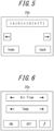
- an object for an operation of returning to the menu screen may be provided in the application. For example, as illustrated in FIG. 5 , an object indicated as "home” may be provided.
- the controller 10 may switch to the menu screen in response to an input to the object indicated as "home”. The user may return to the menu screen once by selecting the object indicated as "home", and then select another object on the menu screen to activate another application corresponding to another vehicle mounted apparatus 80.
- the controller 10 may switch directly to another application during application startup.
- the controller 10 may switch an application in response to an input to the touch sensor 11. With such a configuration, the user can switch an application more speedily without returning to the menu screen.
- the controller 10 may switch the application when a second stage pressing input is made.
- an input to select an object on the operation screen of an application is set as a first stage pressing input.
- a condition may be further added that the second stage pressing input is executed while touching at least two points.
- the second stage pressing input is executed while touching two points.
- the operation screen of an application illustrated in FIG. 6 includes an object indicated as "Air Flow” for air volume setting of an air conditioner.
- the operation screen also includes an object indicated as "Temp” for temperature setting of the air conditioner.
- the operation screen further includes objects indicated as "ON” and "OFF” for setting on /off of the air conditioner.
- the application can be switched regardless of the position on the touch sensor 11 at which a second stage pressing input is made. For example, the application may be switched between that illustrated in FIG. 5 and that illustrated in FIG. 6 . Also, the application may be sequentially switched to another application.
- the controller 10 may switch the application when a slide input to the touch sensor 11 including a predetermined gesture is made. Description of the predetermined gesture will be omitted for being similar to that related to switching of menu screen described above.
- a condition may be further added that the gesture input is executed while touching at least two points. For example, by executing an input that slides while touching with two fingers, a gesture input can be executed while touching two points. With such a configuration, unintended switching of application can be reduced.
- the user can switch an application without viewing the touch sensor 11, namely, without turning their line of sight away from the vehicle forward direction.
- the driving of the vehicle can be performed safely.
- the user can switch an application without returning to the menu screen.
- operational comfort can be improved.
- the controller 10 may execute the control method illustrated in FIGS. 7 and 8 .
- the controller 10 causes the pressing detector 13 to start detection of pressure (Step S11 in FIG. 7 ).
- the controller 10 acquires data based on pressing from the pressing detector 13, and determines whether the data based on pressing is equal to or larger than the first stage threshold value (Step S12).
- Step S12 NO
- the controller 10 proceeds to Step S41 of FIG. 8 .
- Step S12 when the data based on pressing is equal to or larger than the first stage threshold value (Step S12: YES), the controller 10 stores the data based on pressing in the memory 14 (Step S13).
- the controller 10 may cause the tactile sensation presentation unit 12 to present the user with a tactile sensation such as a click feeling corresponding to the first stage pressing input at the time when the data based on pressing is determined to be equal to or larger than the first stage threshold value.
- the controller 10 acquires data based on pressing from the pressing detector 13, and determines whether the data based on pressing is equal to or larger than the second stage threshold value (Step S14).
- Step S14 When the data based on pressing is equal to or larger than the second stage threshold value (Step S14: YES), the controller 10 stores the data based on pressing in the memory 14 (Step S15).
- the controller 10 may cause the tactile sensation presentation unit 12 to present the user with a tactile sensation such as a click feeling corresponding to the second stage pressing input at the time when the data based on pressing is determined to be equal to or larger than the second stage threshold value.
- Step S14 when the data based on pressing is not equal to or larger than the second stage threshold value(Step S14: NO), the controller 10 acquires data based on pressing from the pressing detector 13 and determines whether the data based on pressing is smaller than the first stage threshold value (Step S16). When the data based on pressing is not smaller than the first stage threshold value (Step S17: NO), the controller 10 returns to Step S13.
- Step S16 When the data based on pressing is smaller than the first stage threshold value (Step S16: YES), the controller 10 determines whether the maximum value of the data based on pressing stored in the memory 14 is equal to or larger than the second stage threshold value (Step S17).
- Step S17 NO
- the controller 10 determines that a first stage pressing input has been made (Step S18).
- the controller 10 selects the object associated with the position at which the first stage pressing input was made (Step S19).
- the controller 10 activates the application corresponding to the object.
- the controller 10 outputs apparatus operation information corresponding to the object to the vehicle mounted apparatus 80. Then, the controller 10 ends the processing of the flowchart illustrated in FIG. 7 .
- Step S17 when the data based on pressing is equal to or larger than the second stage threshold value (Step S17: YES), the controller 10 determines that a second stage pressing input has been made (Step S20).
- Step S21 When a menu screen is displayed on the display surface 20a, the controller 10 switches the menu screen (Step S21). When the operation screen of an activated application is displayed on the display surface 20a, the controller 10 switches the application. Then, the controller 10 ends the processing of the flowchart illustrated in FIG. 7 .
- the first stage pressing input and the second stage pressing input are determined after the data based on pressing is determined to be smaller than the first stage threshold value.
- the controller 10 may determine the second stage pressing input at the time when the data based on pressing is determined to be equal to or larger than the second stage threshold value. With such a configuration, operability can be improved.
- the controller 10 may determine the first stage pressing input when the state in which the data based on pressing is equal to or larger than the first stage threshold value and smaller than the second stage threshold value has lasted for a predetermined time.
- Step S12 of FIG. 7 when the data based on pressing is not equal to or larger than the first stage threshold value (Step S12 of FIG. 7 : NO), the controller 10 proceeds to Step S41 of FIG. 8 .
- the controller 10 determines whether the finger touching the touch sensor 11 has slid (Step S41 of FIG. 8 ). When the finger has not slid (Step S41: NO), the controller 10 returns to Step S12 of FIG. 7 .
- Step S41 when the finger has slid (Step S41: YES), the controller 10 determines whether the slide input includes a predetermined gesture (Step S42). When the slide input does not include a predetermined gesture (Step S42: NO), the controller 10 returns to Step S12 of FIG. 7 .
- Step S42 determines that a gesture input has been made (Step S43). At this time, the controller 10 may cause the tactile sensation presentation unit 12 to present a tactile sensation such as a click feeling corresponding to the gesture input.
- the controller switches the menu screen.
- the controller 10 switches the application. Then, the controller 10 ends the processing of the flowchart illustrated in FIG. 8 .
- the user can switch an application without viewing the touch sensor 11, namely, without turning their line of sight away from the vehicle forward direction.
- switching of menu screen and application is executed by pressing input and gesture input. Switching may be executed by one of pressing input and gesture input.
- the user can switch an application without viewing the touch sensor 11, namely, without turning their line of sight away from the vehicle forward direction.
- driving of the vehicle can be performed safely.
- the user can switch an application without returning to the menu screen.
- operational comfort can be improved.
- embodiments according to the present disclosure may be realized as a method executed by a processor included in an apparatus, or as a program or a storage medium recording a program. It is to be understood that there are also included within the scope of the present disclosure.
Landscapes
- Engineering & Computer Science (AREA)
- General Engineering & Computer Science (AREA)
- Theoretical Computer Science (AREA)
- Human Computer Interaction (AREA)
- Physics & Mathematics (AREA)
- General Physics & Mathematics (AREA)
- Mechanical Engineering (AREA)
- User Interface Of Digital Computer (AREA)
- Fittings On The Vehicle Exterior For Carrying Loads, And Devices For Holding Or Mounting Articles (AREA)
Description
- This application claims priority to and the benefit of
Japanese Patent Application No. 2016-032324 filed February 23, 2016 - The present disclosure relates to a vehicular control unit.
- A vehicle is provided with an operation unit for a driver to operate apparatuses mounted on the vehicle (hereinafter, also referred to as "vehicle mounted apparatuses") (for example, see
JP 2002-012091 A -
US 2015/054760 A1 discloses a vehicle heads-up display system.US 2013/275924A1 discloses a system and a method to generate a touch-based user interface that allows users to reliably carry out tasks in a low-attention environment.WO 2015/155973 A1 discloses a touch pad input device for a vehicle.CN 203287883 U discloses an electronic equipment and an information processing device thereof, wherein the electronic equipment comprises a touch-sensitive display unit and a processing unit which is coupled with the same.WO 2013/169854 A2 discloses an electronic device with a touch-sensitive surface, a display, and one or more sensors to detect intensity of contacts with the touch-sensitive surface.WO 2013/169299 A1 discloses a haptic feedback based on input progression.US 2014/362014 A1 discloses systems and methods for pressure-based haptic effects. - The present invention provides a vehicular control unit according to
claim 1, and a vehicular control unit according toclaim 2. - In the accompanying drawings:
-
FIG. 1 is a functional block diagram illustrating a schematic configuration example of a vehicular control unit according to an embodiment; -
FIG. 2 is an arrangement example of a vehicle mounted apparatus and a touch sensor on a center console; -
FIG. 3 is an example of a first menu screen; -
FIG. 4 is an example of a second menu screen; -
FIG. 5 is an example of an application operation screen; -
FIG. 6 is an example of an application operation screen; -
FIG. 7 is a flowchart illustrating an example of a control method for detecting a pressing input; and -
FIG. 8 is a flowchart illustrating an example of a control method for detecting a gesture input. - (Embodiment) A vehicular control unit according to the present embodiment may be a vehicle mounted apparatus.
- [Unit Configuration] As illustrated in
FIG. 1 , avehicular control unit 1 includes acontroller 10, atouch sensor 11, a tactilesensation presentation unit 12, apressing detector 13, and adisplay 20. - The
controller 10 is respectively connected to thetouch sensor 11, the tactilesensation presentation unit 12, thepressing detector 13, and thedisplay 20. Thecontroller 10 is configured to output a signal or information associated with a signal to each of the connected units. Information associated with a signal is also referred to as control information. Thecontroller 10 is configured to acquire control information from each of the connected units. InFIG. 1 , each arrow connecting thecontroller 10 and the respective unit indicates the main direction in which control information is outputted. For example, thecontroller 10 and thetouch sensor 11 are connected by an arrow directed from thetouch sensor 11 to thecontroller 10. In this case, it indicates that control information is mainly outputted from thetouch sensor 11 to thecontroller 10. - The
controller 10 includes amemory 14. Thememory 14 may be constituted by a semiconductor memory or the like. In thememory 14, various kinds of information, a program for operating thevehicular control unit 1, or the like is stored. Thememory 14 may function as a working memory. - The
controller 10 is configured to store control information in thememory 14, and acquire control information from thememory 14. Thecontroller 10 is configured to control each of the connected units in accordance with control information. - The
controller 10 is connected to apparatuses mounted on the vehicle. The apparatuses mounted on the vehicle are also referred to as vehicle mountedapparatuses 80. Thecontroller 10 is configured to output control information for operating the vehicle mountedapparatuses 80 in response to input to thetouch sensor 11. Control information for operating the vehicle mountedapparatuses 80 is also referred to as apparatus operation information. Thecontroller 10 is configured to acquire control information indicating the state of the vehicle mountedapparatuses 80. - In order to operate the vehicle mounted
apparatuses 80, thecontroller 10 is configured to execute applications for operating the vehicle mountedapparatuses 80. The applications for operating the vehicle mountedapparatuses 80 are also simply referred to as applications. Thecontroller 10 is configured to generate apparatus operation information in response to a user's input to an application. Thecontroller 10 is configured to output apparatus operation information to the vehicle mountedapparatuses 80. The vehicle mountedapparatuses 80 are configured to operate based on the apparatus operation information acquired from thecontroller 10. As to the vehicle mountedapparatuses 80 operated by the applications, various kinds are applicable. For example, the vehicle mountedapparatuses 80 may include a car navigation system, an air conditioner, an audio, a television, and a communication apparatus. Details of the applications will be described later. - The
touch sensor 11 is for detecting touch by an object such as a finger or a stylus on thetouch sensor 11. In the following description, it is assumed that thetouch sensor 11 is touched with a finger, however, it makes no difference when thetouch sensor 11 is touched with an object such as a stylus. As a method for thetouch sensor 11 to detect a touch, any method such as an electrostatic capacitance method, a resistive film method, a surface acoustic wave method or an ultrasonic method, an infrared method, an electromagnetic induction method, a load detection method, or the like can be used. - When the
touch sensor 11 detects a finger touch, it acquires the coordinates of the touched position. Thetouch sensor 11 then outputs the coordinates of the touched position as control information to thecontroller 10. The user can make an input corresponding to the touched position by touching thetouch sensor 11 with a finger. In addition, by sliding the finger touching thetouch sensor 11, the user can input a pattern such as a character or a figure corresponding to the slide path. - The tactile
sensation presentation unit 12 is configured to present tactile sensation to the user's finger touching thetouch sensor 11 by generating vibrations of various patterns according to a drive signal acquired from thecontroller 10. That is, thecontroller 10 outputs a drive signal as control information to the tactilesensation presentation unit 12, to thereby start driving of the tactilesensation presentation unit 12. - The tactile
sensation presentation unit 12 is constituted by a piezoelectric element, an ultrasonic vibrator, a vibration motor or an eccentric motor, or the like. For example, the tactilesensation presentation unit 12 generates a vibration based on a vibration pattern corresponding to a click feeling, a material texture, or the like, and presents the tactile sensation such as a click feeling, a material texture, or the like to the user's finger touching thetouch sensor 11. - The
pressing detector 13 is configured to detect pressure generated by the user touching thetouch sensor 11 with a finger, a stylus, or the like and further pressing thetouch sensor 11. Pressure generated by pushing thetouch sensor 11 is also referred to as pressing. Thepressing detector 13 is configured to output data based on pressing as control information to thecontroller 10. - The
pressing detector 13 may be constituted by a strain gage sensor, a piezoelectric element or the like, whose physical or electrical characteristics such as strain, resistance, or voltage change according to pressing. For example, when thepressing detector 13 is constituted by a piezoelectric element, the voltage value of the piezoelectric element, which is an electrical characteristic, varies according to the magnitude of the load caused by pressing against thetouch sensor 11. The voltage value which is an electrical characteristic is included in data based on pressing. The data based on pressing may not only include the voltage value, but also include the magnitude of the load caused by pressing, the resistance value, and the like. - The
pressing detector 13 may be constituted in accordance with the detection method of thetouch sensor 11. For example, when the detection method of thetouch sensor 11 is a resistive film method, the magnitude of resistance according to the size of contact area can be associated with the pressing load on thetouch sensor 11. When thetouch sensor 11 uses an electrostatic capacitance method, the capacitance size can be associated with the pressing load on thetouch sensor 11. With such a configuration, the pressingdetector 13 can be constituted without using a strain gage sensor, a piezoelectric element or the like. - The
controller 10 may determine an input to the operation object at the touched position when the data based on pressing acquired from the pressingdetector 13 is equal to or larger than a predetermined threshold value. Here, data based on pressing equal to or larger than a predetermined threshold value corresponds to pressing equal to or higher than a predetermined pressure. An input determined when data based on pressing is equal to or larger than a predetermined threshold value, namely, when pressing is equal to or higher than a predetermined pressure is also referred to as a pressing input. - The
controller 10 may set multistage threshold values with respect to the magnitude of pressing. According to an embodiment of the present invention, thecontroller 10 sets a first stage threshold value and a second stage threshold value. In the case in which a first stage threshold value and a second stage threshold value are set, thecontroller 10 is configured to determine whether data based on pressing acquired from the pressingdetector 13 has reached the first stage threshold value and the second stage threshold value. Thecontroller 10 executes different control according to the determination result. The second stage threshold value is assumed to be higher than the first stage threshold value. An input when data based on pressing reaches the first stage threshold value and an input when data based on pressing reaches the second stage threshold value are also respectively referred to as a first stage pressing input and a second stage pressing input. In the above description, two threshold value stages are set, however, three or more threshold value stages may be set. - The tactile
sensation presentation unit 12 and thepressing detector 13 may be integrated. When both the tactilesensation presentation unit 12 and thepressing detector 13 are constituted using a piezoelectric element, these can share a piezoelectric element. This is because a piezoelectric element generates a voltage when pressure is applied and deforms when a voltage is applied thereto. - The
display 20 is configured to display characters, images or the like that can be visually recognized by the user, based on control information acquired from thecontroller 10. Thedisplay 20 may be a head-up display. A head-up display is also referred to as a HUD. The HUD is configured to project an image on thefront wind shield 82 of the vehicle (seeFIG. 2 ), and cause the user to visually recognize reflected light of the projected image as a virtual image. - The
display 20 may be a liquid crystal display, an organic or inorganic EL (Electro-Luminescence) display, or the like. A liquid crystal display is also referred to as a LCD. Thedisplay 20 may be provided on the upper part of the center console of the vehicle such that, as far as possible, the user does not need to move the line of sight from the vehicle forward direction while driving the vehicle. Note that thedisplay 20 is not limited to the above configuration. - As illustrated in
FIG. 2 , thetouch sensor 11 is disposed between the vehicle mountedapparatus 80 and theshift lever 81. InFIG. 2 , a HUD is disposed as thedisplay 20. Thedisplay 20 is disposed on the dashboard such that adisplay surface 20a is formed at the center of the lower part of thefront wind shield 82. Thedisplay surface 20a is visually recognized by the driver as a virtual image of the image projected from thedisplay 20. - The
display surface 20a is formed on the extended line of the traveling direction of the vehicle from thetouch sensor 11. With such a configuration, the user can easily operate thetouch sensor 11 by blind touching thetouch sensor 11 while visually recognizing thedisplay surface 20a without turning their line of sight away from the vehicle forward direction. - The
controller 10 of thevehicular control unit 1 according to the present embodiment is configured to execute applications for operating the vehicle mountedapparatuses 80. Each vehicle mountedapparatus 80 is associated with an application for operating it. For example, when the user operates an air conditioner as a vehicle mountedapparatus 80, thecontroller 10 activates an application corresponding to the air conditioner. - The
vehicular control unit 1 includes a menu for selecting and activating an application corresponding to the vehicle mountedapparatus 80 that the user intends to operate. The menu includes, for example, objects for activating applications for operating a car navigation system, an air conditioner and the like. When the user makes a pressing input and selects an object, thecontroller 10 activates an application corresponding to the object. - The objects are associated with predetermined positions on the
touch sensor 11 such that the user can select by pressing input. That is, when a pressing input is made at a predetermined position on thetouch sensor 11, an object associated with the predetermined position is selected. The correspondence relationship between the objects and thetouch sensor 11 is set by thecontroller 10. - The
controller 10 is configured to cause thedisplay 20 to display the correspondence relationship between the objects and thetouch sensor 11 on thedisplay surface 20a. Thedisplay 20 is configured to display such that the shape of thedisplay surface 20a is similar to that of thetouch sensor 11. In the present embodiment, the shape of thetouch sensor 11 and thedisplay surface 20a is assumed to be a rectangle. Note that thetouch sensor 11 and thedisplay surface 20a are not limited to a rectangle and may have other shapes. When an object is associated with the upper left of thetouch sensor 11, thedisplay 20 displays the object on the upper left of thedisplay surface 20a. That is, thedisplay 20 is configured to display on thedisplay surface 20a a menu screen in which objects associated with applications are arranged so as to correspond to the positions on thetouch sensor 11. By associating the positions on thetouch sensor 11 with the display positions of the objects, the user can know the correspondence relationship between the objects and thetouch sensor 11. - In the menu screen according to the present embodiment, it is assumed that the number of objects simultaneously associated with the
touch sensor 11, namely, the number of objects simultaneously displayed on thedisplay surface 20a is four. It is further assumed that the four objects are respectively associated with predetermined positions provided near the four corners of thetouch sensor 11. Note that the number of objects simultaneously associated with thetouch sensor 11 is not limited to four, and may be three or less, or five or more. - As illustrated in
FIG. 3 , thedisplay 20 may display four objects (1) to (4) on thedisplay surface 20a. The object (1) is associated with the upper left area of thetouch sensor 11. In addition, the objects (2) to (4) are respectively associated with the upper right area, the lower left area, and the lower right area of thetouch sensor 11. Although no object is displayed at the center of thedisplay surface 20a, note that this is not necessary. For example, an object associated with the central area of thetouch sensor 11 may be displayed in the central ellipse area. - The
controller 10 is configured to, based on control information acquired from thetouch sensor 11 and thepressing detector 13, determine whether a pressing input is made at a position associated with an object, namely, whether an object is selected. When an object is selected, thecontroller 10 activates an application corresponding to the object. For example, in the case in which the object (1) is associated with an application for operating a car navigation system, thecontroller 10 activates the application for operating a car navigation system in response to the selection of the object (1). - In the example illustrated in
FIG. 3 , the number of objects to be displayed is four. When thevehicular control unit 1 is capable of operating five or more vehicle mountedapparatuses 80, applications that can be activated by the displayed objects are limited to the applications corresponding to the first to fourth vehicle mountedapparatuses 80. That is, in the example illustrated inFIG. 3 , thedisplay 20 cannot display on thedisplay surface 20a the object for activating the application corresponding to the fifth vehicle mountedapparatus 80. In order to display objects for activating applications corresponding to the fifth and subsequent vehicle mountedapparatuses 80, thecontroller 10 is configured to switch the menu screen. The menu screen illustrated inFIG. 3 is also referred to as a first menu screen. The menu screen switched from the first menu screen by thecontroller 10 is also referred to as a second menu screen. - As illustrated in
FIG. 4 , four objects (5) to (8) are displayed on thedisplay surface 20a by thedisplay 20. In this case, the object (5) is associated with the upper left area of thetouch sensor 11. In addition, the objects (6) to (8) are respectively associated with the upper right area, the lower left area, and the lower right area of thetouch sensor 11. The description of the central area of thedisplay surface 20a will be omitted for being similar to that described in relation toFIG. 3 . - The
controller 10 is configured to switch a menu screen in response to an input to thetouch sensor 11. For example, thecontroller 10 may provide an object configured to execute menu switching on the menu screen. Thecontroller 10 may switch the menu screen in response to a pressing input to the object configured to execute menu switching. - In the state in which a menu screen is displayed on the
display surface 20a, thecontroller 10 may switch the menu screen when a second stage pressing input is made. In this case, an input to select an object is set as a first stage pressing input. With such a configuration, it is possible to switch a menu screen without selecting an object, regardless of the position on thetouch sensor 11 at which a second stage pressing input is made. - In the case in which a menu screen is switched in response to a second stage pressing input, a condition may be further added that the second stage pressing input is executed while touching at least two points. According to an embodiment of the present invention, by making a second stage pressing input with two fingers, the second stage pressing input is executed while touching two points. With such a configuration, unintended switching of the menu screen by the user can be reduced.
- In the state in which a menu screen is displayed on the
display surface 20a, thecontroller 10 may switch the menu screen when a slide input including a predetermined gesture is made to thetouch sensor 11. A slide input including a predetermined gesture is also referred to as a gesture input. The predetermined gesture may be, for example, a swipe input that simply slides in one direction. The predetermined gesture may represent a specific character such as Z, V, O, N or the like, according to the path of the slide. The predetermined gesture may represent a specific figure such as a triangle, a square, a star or the like, according to the path of the slide. - In the case in which a menu screen is switched in response to a gesture input, a condition may be further added that the gesture input is executed while touching at least two points. For example, by executing a slide input while touching with two fingers, a gesture input can be executed while touching two points. With such a configuration, switching of menu screen unintended by the user can be reduced.
- By switching a menu screen in the above described way, the user can switch a menu screen without viewing the
touch sensor 11, namely, without turning their line of sight away from the vehicle forward direction. As a result, the driving of the vehicle can be performed safely. - When an application for operating one vehicle mounted
apparatus 80 is activated by thevehicular control unit 1, the user may want to operate another vehicle mountedapparatus 80. In this case, it is possible to operate another vehicle mountedapparatus 80 by switching the application. As one method of switching an application, an object for an operation of returning to the menu screen may be provided in the application. For example, as illustrated inFIG. 5 , an object indicated as "home" may be provided. Thecontroller 10 may switch to the menu screen in response to an input to the object indicated as "home". The user may return to the menu screen once by selecting the object indicated as "home", and then select another object on the menu screen to activate another application corresponding to another vehicle mountedapparatus 80. - As another method of switching an application, the
controller 10 may switch directly to another application during application startup. Thecontroller 10 may switch an application in response to an input to thetouch sensor 11. With such a configuration, the user can switch an application more speedily without returning to the menu screen. - In a state in which the operation screen of an application is displayed on the
display surface 20a, thecontroller 10 may switch the application when a second stage pressing input is made. In this case, an input to select an object on the operation screen of an application is set as a first stage pressing input. With such a configuration, the user can switch an application without selecting an object, regardless of the position on thetouch sensor 11 at which a second stage pressing input is made. - In the case in which an application is switched in response to a second stage pressing input, a condition may be further added that the second stage pressing input is executed while touching at least two points. According to an embodiment of the present invention, by executing a second stage pressing input with two fingers, the second stage pressing input is executed while touching two points. With such a configuration, unintended switching of an application can be reduced.
- The operation screen of an application illustrated in
FIG. 6 includes an object indicated as "Air Flow" for air volume setting of an air conditioner. The operation screen also includes an object indicated as "Temp" for temperature setting of the air conditioner. The operation screen further includes objects indicated as "ON" and "OFF" for setting on /off of the air conditioner. InFIG. 6 , irrespective of the presence or absence of the objects, the application can be switched regardless of the position on thetouch sensor 11 at which a second stage pressing input is made. For example, the application may be switched between that illustrated inFIG. 5 and that illustrated inFIG. 6 . Also, the application may be sequentially switched to another application. - In the state in which the operation screen of an application is displayed on the
display surface 20a, thecontroller 10 may switch the application when a slide input to thetouch sensor 11 including a predetermined gesture is made. Description of the predetermined gesture will be omitted for being similar to that related to switching of menu screen described above. - In the case in which an application is switched in response to a gesture input, a condition may be further added that the gesture input is executed while touching at least two points. For example, by executing an input that slides while touching with two fingers, a gesture input can be executed while touching two points. With such a configuration, unintended switching of application can be reduced.
- By switching an application in the above described way, the user can switch an application without viewing the
touch sensor 11, namely, without turning their line of sight away from the vehicle forward direction. As a result, the driving of the vehicle can be performed safely. In addition, the user can switch an application without returning to the menu screen. As a result, operational comfort can be improved. - The
controller 10 may execute the control method illustrated inFIGS. 7 and8 . - The
controller 10 causes thepressing detector 13 to start detection of pressure (Step S11 inFIG. 7 ). - Then, the
controller 10 acquires data based on pressing from the pressingdetector 13, and determines whether the data based on pressing is equal to or larger than the first stage threshold value (Step S12). - When the data based on pressing is not equal to or larger than the first stage threshold value (Step S12: NO), the
controller 10 proceeds to Step S41 ofFIG. 8 . - On the other hand, when the data based on pressing is equal to or larger than the first stage threshold value (Step S12: YES), the
controller 10 stores the data based on pressing in the memory 14 (Step S13). Thecontroller 10 may cause the tactilesensation presentation unit 12 to present the user with a tactile sensation such as a click feeling corresponding to the first stage pressing input at the time when the data based on pressing is determined to be equal to or larger than the first stage threshold value. - The
controller 10 acquires data based on pressing from the pressingdetector 13, and determines whether the data based on pressing is equal to or larger than the second stage threshold value (Step S14). - When the data based on pressing is equal to or larger than the second stage threshold value (Step S14: YES), the
controller 10 stores the data based on pressing in the memory 14 (Step S15). Thecontroller 10 may cause the tactilesensation presentation unit 12 to present the user with a tactile sensation such as a click feeling corresponding to the second stage pressing input at the time when the data based on pressing is determined to be equal to or larger than the second stage threshold value. - On the other hand, when the data based on pressing is not equal to or larger than the second stage threshold value(Step S14: NO), the
controller 10 acquires data based on pressing from the pressingdetector 13 and determines whether the data based on pressing is smaller than the first stage threshold value (Step S16). When the data based on pressing is not smaller than the first stage threshold value (Step S17: NO), thecontroller 10 returns to Step S13. - When the data based on pressing is smaller than the first stage threshold value (Step S16: YES), the
controller 10 determines whether the maximum value of the data based on pressing stored in thememory 14 is equal to or larger than the second stage threshold value (Step S17). - When the maximum value of the data based on pressing is not equal to or larger than the second stage threshold value (Step S17: NO), the
controller 10 determines that a first stage pressing input has been made (Step S18). - Then, the
controller 10 selects the object associated with the position at which the first stage pressing input was made (Step S19). When a menu screen is displayed on thedisplay surface 20a, thecontroller 10 activates the application corresponding to the object. When the operation screen of an activated application is displayed on thedisplay surface 20a, thecontroller 10 outputs apparatus operation information corresponding to the object to the vehicle mountedapparatus 80. Then, thecontroller 10 ends the processing of the flowchart illustrated inFIG. 7 . - On the other hand, when the data based on pressing is equal to or larger than the second stage threshold value (Step S17: YES), the
controller 10 determines that a second stage pressing input has been made (Step S20). - When a menu screen is displayed on the
display surface 20a, thecontroller 10 switches the menu screen (Step S21). When the operation screen of an activated application is displayed on thedisplay surface 20a, thecontroller 10 switches the application. Then, thecontroller 10 ends the processing of the flowchart illustrated inFIG. 7 . - In the processing illustrated in the flowchart of
FIG. 7 , the first stage pressing input and the second stage pressing input are determined after the data based on pressing is determined to be smaller than the first stage threshold value. With such a configuration, it is possible to cope with multistage inputs of the third or more stages. On the other hand, if thecontroller 10 is configured to not accept a pressing input of the third or more stages, thecontroller 10 may determine the second stage pressing input at the time when the data based on pressing is determined to be equal to or larger than the second stage threshold value. With such a configuration, operability can be improved. - After the data based on pressing is determined to be equal to or larger than the first stage threshold value, the
controller 10 may determine the first stage pressing input when the state in which the data based on pressing is equal to or larger than the first stage threshold value and smaller than the second stage threshold value has lasted for a predetermined time. - <Gesture Input> In Step S12 of
FIG. 7 , when the data based on pressing is not equal to or larger than the first stage threshold value (Step S12 ofFIG. 7 : NO), thecontroller 10 proceeds to Step S41 ofFIG. 8 . Thecontroller 10 determines whether the finger touching thetouch sensor 11 has slid (Step S41 ofFIG. 8 ). When the finger has not slid (Step S41: NO), thecontroller 10 returns to Step S12 ofFIG. 7 . - On the other hand, when the finger has slid (Step S41: YES), the
controller 10 determines whether the slide input includes a predetermined gesture (Step S42). When the slide input does not include a predetermined gesture (Step S42: NO), thecontroller 10 returns to Step S12 ofFIG. 7 . - On the other hand, when the slide input includes a predetermined gesture (Step S42: YES), the
controller 10 determines that a gesture input has been made (Step S43). At this time, thecontroller 10 may cause the tactilesensation presentation unit 12 to present a tactile sensation such as a click feeling corresponding to the gesture input. - When a menu screen is displayed on the
display surface 20a, the controller switches the menu screen. When the operation screen of an application is displayed on thedisplay surface 20a, thecontroller 10 switches the application. Then, thecontroller 10 ends the processing of the flowchart illustrated inFIG. 8 . - By executing the control method illustrated in the flowcharts of
FIGS. 7 and8 , the user can switch an application without viewing thetouch sensor 11, namely, without turning their line of sight away from the vehicle forward direction. - In the flowcharts of
FIGS. 7 and8 , switching of menu screen and application is executed by pressing input and gesture input. Switching may be executed by one of pressing input and gesture input. - According to the
vehicular control unit 1 of the present embodiment, the user can switch an application without viewing thetouch sensor 11, namely, without turning their line of sight away from the vehicle forward direction. As a result, driving of the vehicle can be performed safely. Further, the user can switch an application without returning to the menu screen. As a result, operational comfort can be improved. - Although an embodiment according to the present disclosure has been described based on the accompanying drawings and examples, it is to be noted that various changes and modifications will be apparent to those skilled in the art based on this disclosure. Thus, such changes and modifications are to be understood as included within the scope of this disclosure. For example, functions and the like included in various components and steps may be reordered in any logically consistent way. Furthermore, components or steps may be combined into one or divided. Although an embodiment according to the present disclosure has been described centering on an apparatus, it is to be noted that embodiments according to the present disclosure may be realized as a method including steps executed by each component of an apparatus. Further, although an embodiment according to the present disclosure has been described centering on an apparatus, it is to be noted that embodiments according to the present disclosure may be realized as a method executed by a processor included in an apparatus, or as a program or a storage medium recording a program. It is to be understood that there are also included within the scope of the present disclosure.
-
- 1
- Vehicular control unit
- 10
- Controller
- 11
- Touch sensor
- 12
- Tactile sensation presentation unit
- 13
- Pressing detector
- 14
- Memory
- 20
- Display
- 20a
- Display surface
- 80
- Vehicle mounted apparatus
- 81
- Shift lever
- 82
- Front wind shield
Claims (2)
- A vehicular control unit (1), comprising:a touch sensor (11) for placement in a first location in a vehicle;a pressing detector (13) for detecting pressing against the touch sensor (11);a display (20) for placement at a second location relatively distant from said first location in said vehicle, said display (20) configured to display a first menu screen including one or more first objects each for activating a respective different application for operating a corresponding different apparatus (80) mounted on said vehicle, and to display a second menu screen including one or more second objects each for activating a respective different application for operating a corresponding different apparatus (80) mounted on said vehicle, wherein the second objects correspond to different apparatuses (80) than the first objects;a controller (10) configured to:acquire data based on the pressing from the pressing detector (13), the data based on the pressing indicating a detected pressure;set a first stage threshold value and a second stage threshold value larger than the first stage threshold value, which are related to the data based on the pressing;activate an application corresponding to an object when a touch is exerted in an area on the touch sensor (11) corresponding with the area where said object is displayed on the display (20) and when the data based on the pressing is equal to or larger than the first stage threshold value but not equal to or larger than the second stage threshold value; andswitch the first menu screen to the second menu screen when the data based on pressing reaches the second stage threshold value and at least two touch points are detected.
- A vehicular control unit (1), comprising:a touch sensor (11) for placement in a first location in a vehicle;a pressing detector (13) for detecting pressing against the touch sensor (11);a display (20) for placement at a second location relatively distant from said first location in said vehicle, configured to display a first operation screen of a first activated application comprising one or more selectable application specific objects each associated with a respective application specific function, and a second operation screen of a second activated application comprising one or more selectable application specific objects each associated with a respective application specific function; anda controller (10) configured to:acquire data based on the pressing from the pressing detector (13), the data based on the pressing indicating a detected pressure;set a first stage threshold value and a second stage threshold value larger than the first stage threshold value, which are related to the data based on the pressing;activate the application specific function corresponding to an object when a touch is exerted in an area on the touch sensor (11) corresponding with the area where said object is displayed on the display (20) and when the data based on the pressing is equal to or larger than the first stage threshold value but not equal to or larger than the second stage threshold value; andswitch from displaying of the first operation screen to displaying of the second operation screen when the data based on pressing reaches the second stage threshold value and at least two touch points are detected.
Applications Claiming Priority (2)
| Application Number | Priority Date | Filing Date | Title |
|---|---|---|---|
| JP2016032324A JP2017149225A (en) | 2016-02-23 | 2016-02-23 | Vehicle control unit |
| PCT/JP2017/004444 WO2017145746A1 (en) | 2016-02-23 | 2017-02-07 | Control unit for vehicle |
Publications (3)
| Publication Number | Publication Date |
|---|---|
| EP3421300A1 EP3421300A1 (en) | 2019-01-02 |
| EP3421300A4 EP3421300A4 (en) | 2019-12-18 |
| EP3421300B1 true EP3421300B1 (en) | 2024-09-18 |
Family
ID=59686121
Family Applications (1)
| Application Number | Title | Priority Date | Filing Date |
|---|---|---|---|
| EP17756187.5A Active EP3421300B1 (en) | 2016-02-23 | 2017-02-07 | Control unit for vehicle |
Country Status (4)
| Country | Link |
|---|---|
| US (1) | US11221735B2 (en) |
| EP (1) | EP3421300B1 (en) |
| JP (1) | JP2017149225A (en) |
| WO (1) | WO2017145746A1 (en) |
Families Citing this family (4)
| Publication number | Priority date | Publication date | Assignee | Title |
|---|---|---|---|---|
| CN107037956A (en) * | 2016-11-01 | 2017-08-11 | 华为机器有限公司 | A terminal and method for switching applications thereof |
| TWI678656B (en) * | 2018-05-09 | 2019-12-01 | 和碩聯合科技股份有限公司 | Computer system and operational method thereof |
| JP7310301B2 (en) * | 2019-05-24 | 2023-07-19 | 株式会社デンソー | Control system and computer program |
| JP7710349B2 (en) * | 2021-09-24 | 2025-07-18 | フォルシアクラリオン・エレクトロニクス株式会社 | Control value setting device and control value setting program |
Citations (2)
| Publication number | Priority date | Publication date | Assignee | Title |
|---|---|---|---|---|
| EP1677180A1 (en) * | 2004-12-30 | 2006-07-05 | Volkswagen Aktiengesellschaft | Touchscreen capable of detecting two simultaneous touch locations |
| US20100295797A1 (en) * | 2009-05-21 | 2010-11-25 | Sony Computer Entertainment America Inc. | Continuous and dynamic scene decomposition for user interface |
Family Cites Families (24)
| Publication number | Priority date | Publication date | Assignee | Title |
|---|---|---|---|---|
| JP4675458B2 (en) | 2000-06-28 | 2011-04-20 | 京セラ株式会社 | Hands-free device |
| WO2010090033A1 (en) * | 2009-02-06 | 2010-08-12 | パナソニック株式会社 | Image display device |
| US9684521B2 (en) | 2010-01-26 | 2017-06-20 | Apple Inc. | Systems having discrete and continuous gesture recognizers |
| JP5889519B2 (en) * | 2010-06-30 | 2016-03-22 | 京セラ株式会社 | Tactile sensation presentation apparatus and control method of tactile sensation presentation apparatus |
| CN106095418B (en) * | 2010-12-20 | 2019-09-13 | 苹果公司 | Event recognition |
| JP5654114B2 (en) * | 2011-02-23 | 2015-01-14 | 京セラ株式会社 | Electronic device with touch sensor |
| JP2013210963A (en) * | 2012-03-30 | 2013-10-10 | Denso Corp | Display control device and program |
| JP5790578B2 (en) * | 2012-04-10 | 2015-10-07 | 株式会社デンソー | Display system, display device, and operation device |
| US20130275924A1 (en) | 2012-04-16 | 2013-10-17 | Nuance Communications, Inc. | Low-attention gestural user interface |
| WO2013169303A1 (en) | 2012-05-09 | 2013-11-14 | Yknots Industries Llc | Adaptive haptic feedback for electronic devices |
| CN109298789B (en) | 2012-05-09 | 2021-12-31 | 苹果公司 | Device, method and graphical user interface for providing feedback on activation status |
| JP2014046867A (en) * | 2012-08-31 | 2014-03-17 | Sony Corp | Input device |
| JP5954145B2 (en) * | 2012-12-04 | 2016-07-20 | 株式会社デンソー | Input device |
| US20140267066A1 (en) * | 2013-03-14 | 2014-09-18 | Nomovok Co. Ltd. | Vehicle dashboard device with a touchable mobile remote control |
| US9658740B2 (en) * | 2013-03-15 | 2017-05-23 | Apple Inc. | Device, method, and graphical user interface for managing concurrently open software applications |
| CN105556423B (en) * | 2013-06-11 | 2019-01-15 | 意美森公司 | System and method for pressure-based haptic effects |
| JP5814332B2 (en) * | 2013-12-13 | 2015-11-17 | 本田技研工業株式会社 | Application control program, method, apparatus, and recording medium |
| US10996844B2 (en) * | 2013-06-12 | 2021-05-04 | Honda Motor Co., Ltd. | Program, method, and device for controlling application, and recording medium |
| US20150022465A1 (en) * | 2013-07-18 | 2015-01-22 | Honda Motor Co., Ltd. | Touchpad for user to vehicle interaction |
| WO2015017693A1 (en) | 2013-07-31 | 2015-02-05 | Smarthud, Inc. | Vehicle use portable heads-up display |
| WO2015083267A1 (en) * | 2013-12-05 | 2015-06-11 | 三菱電機株式会社 | Display control device, and display control method |
| JP6273989B2 (en) * | 2014-04-10 | 2018-02-07 | 株式会社デンソー | Operating device and vehicle |
| US10289260B2 (en) * | 2014-08-27 | 2019-05-14 | Honda Motor Co., Ltd. | Systems and techniques for application multi-tasking |
| US9645732B2 (en) * | 2015-03-08 | 2017-05-09 | Apple Inc. | Devices, methods, and graphical user interfaces for displaying and using menus |
-
2016
- 2016-02-23 JP JP2016032324A patent/JP2017149225A/en active Pending
-
2017
- 2017-02-07 WO PCT/JP2017/004444 patent/WO2017145746A1/en not_active Ceased
- 2017-02-07 EP EP17756187.5A patent/EP3421300B1/en active Active
- 2017-02-07 US US16/078,640 patent/US11221735B2/en active Active
Patent Citations (2)
| Publication number | Priority date | Publication date | Assignee | Title |
|---|---|---|---|---|
| EP1677180A1 (en) * | 2004-12-30 | 2006-07-05 | Volkswagen Aktiengesellschaft | Touchscreen capable of detecting two simultaneous touch locations |
| US20100295797A1 (en) * | 2009-05-21 | 2010-11-25 | Sony Computer Entertainment America Inc. | Continuous and dynamic scene decomposition for user interface |
Also Published As
| Publication number | Publication date |
|---|---|
| JP2017149225A (en) | 2017-08-31 |
| EP3421300A1 (en) | 2019-01-02 |
| US11221735B2 (en) | 2022-01-11 |
| EP3421300A4 (en) | 2019-12-18 |
| US20190018556A1 (en) | 2019-01-17 |
| WO2017145746A1 (en) | 2017-08-31 |
Similar Documents
| Publication | Publication Date | Title |
|---|---|---|
| EP3422156B1 (en) | Control unit for vehicle and control method for the same | |
| EP2447823A2 (en) | Method and apparatus for gesture recognition | |
| JP5644962B2 (en) | Operating device | |
| CN107111397B (en) | For the method for the operating device of operation motor vehicle and operating device and motor vehicle in different operation modes | |
| JP6277786B2 (en) | Vehicle control device | |
| JP2014102660A (en) | Manipulation assistance system, manipulation assistance method, and computer program | |
| CN102741794A (en) | Handling tactile inputs | |
| US9335822B2 (en) | Method and system for providing haptic effects based on haptic context information | |
| US20190391736A1 (en) | Input device and input method | |
| US11221735B2 (en) | Vehicular control unit | |
| CN105683869A (en) | Operating device capable of keyless operation | |
| JP7043166B2 (en) | Display control device, display control system and display control method | |
| JP2014102656A (en) | Manipulation assistance system, manipulation assistance method, and computer program | |
| JP2018195134A (en) | On-vehicle information processing system | |
| KR101422060B1 (en) | Information display apparatus and method for vehicle using touch-pad, and information input module thereof | |
| JP2018136616A (en) | Display operation system | |
| JP2018010472A (en) | In-vehicle electronic equipment operation device and in-vehicle electronic equipment operation method | |
| US20180232115A1 (en) | In-vehicle input device and in-vehicle input device control method | |
| KR101480775B1 (en) | Information display apparatus and method for vehicle using touch-pad, and information input module thereof | |
| US20180292924A1 (en) | Input processing apparatus | |
| JP2014102657A (en) | Manipulation assistance system, manipulation assistance method, and computer program | |
| JP2017187922A (en) | In-vehicle information processing system | |
| JP2017187919A (en) | In-vehicle information processing system | |
| JP2025178122A (en) | Providing a user interface for controlling a touchscreen in a vehicle using multi-finger gestures | |
| JP2018122827A (en) | On-vehicle information input device and on-vehicle information input system |
Legal Events
| Date | Code | Title | Description |
|---|---|---|---|
| STAA | Information on the status of an ep patent application or granted ep patent |
Free format text: STATUS: THE INTERNATIONAL PUBLICATION HAS BEEN MADE |
|
| PUAI | Public reference made under article 153(3) epc to a published international application that has entered the european phase |
Free format text: ORIGINAL CODE: 0009012 |
|
| STAA | Information on the status of an ep patent application or granted ep patent |
Free format text: STATUS: REQUEST FOR EXAMINATION WAS MADE |
|
| 17P | Request for examination filed |
Effective date: 20180821 |
|
| AK | Designated contracting states |
Kind code of ref document: A1 Designated state(s): AL AT BE BG CH CY CZ DE DK EE ES FI FR GB GR HR HU IE IS IT LI LT LU LV MC MK MT NL NO PL PT RO RS SE SI SK SM TR |
|
| AX | Request for extension of the european patent |
Extension state: BA ME |
|
| DAV | Request for validation of the european patent (deleted) | ||
| DAX | Request for extension of the european patent (deleted) | ||
| A4 | Supplementary search report drawn up and despatched |
Effective date: 20191114 |
|
| RIC1 | Information provided on ipc code assigned before grant |
Ipc: G06F 3/0482 20130101ALI20191108BHEP Ipc: G06F 3/0488 20130101ALI20191108BHEP Ipc: B60R 16/02 20060101AFI20191108BHEP Ipc: B60R 11/02 20060101ALI20191108BHEP Ipc: G06F 3/0485 20130101ALI20191108BHEP Ipc: G06F 3/0354 20130101ALI20191108BHEP |
|
| STAA | Information on the status of an ep patent application or granted ep patent |
Free format text: STATUS: EXAMINATION IS IN PROGRESS |
|
| 17Q | First examination report despatched |
Effective date: 20210413 |
|
| P01 | Opt-out of the competence of the unified patent court (upc) registered |
Effective date: 20230505 |
|
| GRAP | Despatch of communication of intention to grant a patent |
Free format text: ORIGINAL CODE: EPIDOSNIGR1 |
|
| STAA | Information on the status of an ep patent application or granted ep patent |
Free format text: STATUS: GRANT OF PATENT IS INTENDED |
|
| INTG | Intention to grant announced |
Effective date: 20240408 |
|
| RAP3 | Party data changed (applicant data changed or rights of an application transferred) |
Owner name: KYOCERA CORPORATION |
|
| RIN1 | Information on inventor provided before grant (corrected) |
Inventor name: MURAKAMI KAZUHIRO Inventor name: HATTORI SHIGETO |
|
| GRAS | Grant fee paid |
Free format text: ORIGINAL CODE: EPIDOSNIGR3 |
|
| GRAA | (expected) grant |
Free format text: ORIGINAL CODE: 0009210 |
|
| STAA | Information on the status of an ep patent application or granted ep patent |
Free format text: STATUS: THE PATENT HAS BEEN GRANTED |
|
| AK | Designated contracting states |
Kind code of ref document: B1 Designated state(s): AL AT BE BG CH CY CZ DE DK EE ES FI FR GB GR HR HU IE IS IT LI LT LU LV MC MK MT NL NO PL PT RO RS SE SI SK SM TR |
|
| REG | Reference to a national code |
Ref country code: GB Ref legal event code: FG4D |
|
| REG | Reference to a national code |
Ref country code: CH Ref legal event code: EP |
|
| REG | Reference to a national code |
Ref country code: IE Ref legal event code: FG4D |
|
| REG | Reference to a national code |
Ref country code: DE Ref legal event code: R096 Ref document number: 602017084922 Country of ref document: DE |
|
| REG | Reference to a national code |
Ref country code: LT Ref legal event code: MG9D |
|
| PG25 | Lapsed in a contracting state [announced via postgrant information from national office to epo] |
Ref country code: NO Free format text: LAPSE BECAUSE OF FAILURE TO SUBMIT A TRANSLATION OF THE DESCRIPTION OR TO PAY THE FEE WITHIN THE PRESCRIBED TIME-LIMIT Effective date: 20241218 |
|
| PG25 | Lapsed in a contracting state [announced via postgrant information from national office to epo] |
Ref country code: GR Free format text: LAPSE BECAUSE OF FAILURE TO SUBMIT A TRANSLATION OF THE DESCRIPTION OR TO PAY THE FEE WITHIN THE PRESCRIBED TIME-LIMIT Effective date: 20241219 Ref country code: FI Free format text: LAPSE BECAUSE OF FAILURE TO SUBMIT A TRANSLATION OF THE DESCRIPTION OR TO PAY THE FEE WITHIN THE PRESCRIBED TIME-LIMIT Effective date: 20240918 |
|
| PG25 | Lapsed in a contracting state [announced via postgrant information from national office to epo] |
Ref country code: BG Free format text: LAPSE BECAUSE OF FAILURE TO SUBMIT A TRANSLATION OF THE DESCRIPTION OR TO PAY THE FEE WITHIN THE PRESCRIBED TIME-LIMIT Effective date: 20240918 |
|
| PG25 | Lapsed in a contracting state [announced via postgrant information from national office to epo] |
Ref country code: LV Free format text: LAPSE BECAUSE OF FAILURE TO SUBMIT A TRANSLATION OF THE DESCRIPTION OR TO PAY THE FEE WITHIN THE PRESCRIBED TIME-LIMIT Effective date: 20240918 |
|
| PG25 | Lapsed in a contracting state [announced via postgrant information from national office to epo] |
Ref country code: HR Free format text: LAPSE BECAUSE OF FAILURE TO SUBMIT A TRANSLATION OF THE DESCRIPTION OR TO PAY THE FEE WITHIN THE PRESCRIBED TIME-LIMIT Effective date: 20240918 |
|
| REG | Reference to a national code |
Ref country code: NL Ref legal event code: MP Effective date: 20240918 |
|
| PG25 | Lapsed in a contracting state [announced via postgrant information from national office to epo] |
Ref country code: RS Free format text: LAPSE BECAUSE OF FAILURE TO SUBMIT A TRANSLATION OF THE DESCRIPTION OR TO PAY THE FEE WITHIN THE PRESCRIBED TIME-LIMIT Effective date: 20241218 |
|
| PG25 | Lapsed in a contracting state [announced via postgrant information from national office to epo] |
Ref country code: RS Free format text: LAPSE BECAUSE OF FAILURE TO SUBMIT A TRANSLATION OF THE DESCRIPTION OR TO PAY THE FEE WITHIN THE PRESCRIBED TIME-LIMIT Effective date: 20241218 Ref country code: NO Free format text: LAPSE BECAUSE OF FAILURE TO SUBMIT A TRANSLATION OF THE DESCRIPTION OR TO PAY THE FEE WITHIN THE PRESCRIBED TIME-LIMIT Effective date: 20241218 Ref country code: LV Free format text: LAPSE BECAUSE OF FAILURE TO SUBMIT A TRANSLATION OF THE DESCRIPTION OR TO PAY THE FEE WITHIN THE PRESCRIBED TIME-LIMIT Effective date: 20240918 Ref country code: HR Free format text: LAPSE BECAUSE OF FAILURE TO SUBMIT A TRANSLATION OF THE DESCRIPTION OR TO PAY THE FEE WITHIN THE PRESCRIBED TIME-LIMIT Effective date: 20240918 Ref country code: GR Free format text: LAPSE BECAUSE OF FAILURE TO SUBMIT A TRANSLATION OF THE DESCRIPTION OR TO PAY THE FEE WITHIN THE PRESCRIBED TIME-LIMIT Effective date: 20241219 Ref country code: FI Free format text: LAPSE BECAUSE OF FAILURE TO SUBMIT A TRANSLATION OF THE DESCRIPTION OR TO PAY THE FEE WITHIN THE PRESCRIBED TIME-LIMIT Effective date: 20240918 Ref country code: BG Free format text: LAPSE BECAUSE OF FAILURE TO SUBMIT A TRANSLATION OF THE DESCRIPTION OR TO PAY THE FEE WITHIN THE PRESCRIBED TIME-LIMIT Effective date: 20240918 |
|
| REG | Reference to a national code |
Ref country code: AT Ref legal event code: MK05 Ref document number: 1724439 Country of ref document: AT Kind code of ref document: T Effective date: 20240918 |
|
| PG25 | Lapsed in a contracting state [announced via postgrant information from national office to epo] |
Ref country code: NL Free format text: LAPSE BECAUSE OF FAILURE TO SUBMIT A TRANSLATION OF THE DESCRIPTION OR TO PAY THE FEE WITHIN THE PRESCRIBED TIME-LIMIT Effective date: 20240918 |
|
| PG25 | Lapsed in a contracting state [announced via postgrant information from national office to epo] |
Ref country code: PT Free format text: LAPSE BECAUSE OF FAILURE TO SUBMIT A TRANSLATION OF THE DESCRIPTION OR TO PAY THE FEE WITHIN THE PRESCRIBED TIME-LIMIT Effective date: 20250120 Ref country code: IS Free format text: LAPSE BECAUSE OF FAILURE TO SUBMIT A TRANSLATION OF THE DESCRIPTION OR TO PAY THE FEE WITHIN THE PRESCRIBED TIME-LIMIT Effective date: 20250118 |
|
| PG25 | Lapsed in a contracting state [announced via postgrant information from national office to epo] |
Ref country code: RO Free format text: LAPSE BECAUSE OF FAILURE TO SUBMIT A TRANSLATION OF THE DESCRIPTION OR TO PAY THE FEE WITHIN THE PRESCRIBED TIME-LIMIT Effective date: 20240918 Ref country code: SM Free format text: LAPSE BECAUSE OF FAILURE TO SUBMIT A TRANSLATION OF THE DESCRIPTION OR TO PAY THE FEE WITHIN THE PRESCRIBED TIME-LIMIT Effective date: 20240918 |
|
| PG25 | Lapsed in a contracting state [announced via postgrant information from national office to epo] |
Ref country code: ES Free format text: LAPSE BECAUSE OF FAILURE TO SUBMIT A TRANSLATION OF THE DESCRIPTION OR TO PAY THE FEE WITHIN THE PRESCRIBED TIME-LIMIT Effective date: 20240918 |
|
| PG25 | Lapsed in a contracting state [announced via postgrant information from national office to epo] |
Ref country code: AT Free format text: LAPSE BECAUSE OF FAILURE TO SUBMIT A TRANSLATION OF THE DESCRIPTION OR TO PAY THE FEE WITHIN THE PRESCRIBED TIME-LIMIT Effective date: 20240918 Ref country code: EE Free format text: LAPSE BECAUSE OF FAILURE TO SUBMIT A TRANSLATION OF THE DESCRIPTION OR TO PAY THE FEE WITHIN THE PRESCRIBED TIME-LIMIT Effective date: 20240918 |
|
| PG25 | Lapsed in a contracting state [announced via postgrant information from national office to epo] |
Ref country code: PL Free format text: LAPSE BECAUSE OF FAILURE TO SUBMIT A TRANSLATION OF THE DESCRIPTION OR TO PAY THE FEE WITHIN THE PRESCRIBED TIME-LIMIT Effective date: 20240918 Ref country code: CZ Free format text: LAPSE BECAUSE OF FAILURE TO SUBMIT A TRANSLATION OF THE DESCRIPTION OR TO PAY THE FEE WITHIN THE PRESCRIBED TIME-LIMIT Effective date: 20240918 |
|
| PG25 | Lapsed in a contracting state [announced via postgrant information from national office to epo] |
Ref country code: IT Free format text: LAPSE BECAUSE OF FAILURE TO SUBMIT A TRANSLATION OF THE DESCRIPTION OR TO PAY THE FEE WITHIN THE PRESCRIBED TIME-LIMIT Effective date: 20240918 Ref country code: SK Free format text: LAPSE BECAUSE OF FAILURE TO SUBMIT A TRANSLATION OF THE DESCRIPTION OR TO PAY THE FEE WITHIN THE PRESCRIBED TIME-LIMIT Effective date: 20240918 |
|
| REG | Reference to a national code |
Ref country code: DE Ref legal event code: R097 Ref document number: 602017084922 Country of ref document: DE |
|
| PG25 | Lapsed in a contracting state [announced via postgrant information from national office to epo] |
Ref country code: DK Free format text: LAPSE BECAUSE OF FAILURE TO SUBMIT A TRANSLATION OF THE DESCRIPTION OR TO PAY THE FEE WITHIN THE PRESCRIBED TIME-LIMIT Effective date: 20240918 |
|
| PLBE | No opposition filed within time limit |
Free format text: ORIGINAL CODE: 0009261 |
|
| STAA | Information on the status of an ep patent application or granted ep patent |
Free format text: STATUS: NO OPPOSITION FILED WITHIN TIME LIMIT |
|
| 26N | No opposition filed |
Effective date: 20250619 |
|
| PG25 | Lapsed in a contracting state [announced via postgrant information from national office to epo] |
Ref country code: SE Free format text: LAPSE BECAUSE OF FAILURE TO SUBMIT A TRANSLATION OF THE DESCRIPTION OR TO PAY THE FEE WITHIN THE PRESCRIBED TIME-LIMIT Effective date: 20240918 |
|
| PG25 | Lapsed in a contracting state [announced via postgrant information from national office to epo] |
Ref country code: MC Free format text: LAPSE BECAUSE OF FAILURE TO SUBMIT A TRANSLATION OF THE DESCRIPTION OR TO PAY THE FEE WITHIN THE PRESCRIBED TIME-LIMIT Effective date: 20240918 |
|
| REG | Reference to a national code |
Ref country code: CH Ref legal event code: PL |
|
| PG25 | Lapsed in a contracting state [announced via postgrant information from national office to epo] |
Ref country code: LU Free format text: LAPSE BECAUSE OF NON-PAYMENT OF DUE FEES Effective date: 20250207 |
|
| PG25 | Lapsed in a contracting state [announced via postgrant information from national office to epo] |
Ref country code: CH Free format text: LAPSE BECAUSE OF NON-PAYMENT OF DUE FEES Effective date: 20250228 |
|
| GBPC | Gb: european patent ceased through non-payment of renewal fee |
Effective date: 20250207 |
|
| REG | Reference to a national code |
Ref country code: BE Ref legal event code: MM Effective date: 20250228 |
|
| PG25 | Lapsed in a contracting state [announced via postgrant information from national office to epo] |
Ref country code: GB Free format text: LAPSE BECAUSE OF NON-PAYMENT OF DUE FEES Effective date: 20250207 |
|
| PG25 | Lapsed in a contracting state [announced via postgrant information from national office to epo] |
Ref country code: FR Free format text: LAPSE BECAUSE OF NON-PAYMENT OF DUE FEES Effective date: 20250228 |
|
| PG25 | Lapsed in a contracting state [announced via postgrant information from national office to epo] |
Ref country code: BE Free format text: LAPSE BECAUSE OF NON-PAYMENT OF DUE FEES Effective date: 20250228 |
|
| PG25 | Lapsed in a contracting state [announced via postgrant information from national office to epo] |
Ref country code: IE Free format text: LAPSE BECAUSE OF NON-PAYMENT OF DUE FEES Effective date: 20250207 |
|
| PGFP | Annual fee paid to national office [announced via postgrant information from national office to epo] |
Ref country code: DE Payment date: 20251230 Year of fee payment: 10 |