EP3421191A1 - Capteur de sécurisation d'une machine - Google Patents
Capteur de sécurisation d'une machine Download PDFInfo
- Publication number
- EP3421191A1 EP3421191A1 EP18170726.6A EP18170726A EP3421191A1 EP 3421191 A1 EP3421191 A1 EP 3421191A1 EP 18170726 A EP18170726 A EP 18170726A EP 3421191 A1 EP3421191 A1 EP 3421191A1
- Authority
- EP
- European Patent Office
- Prior art keywords
- sensor
- machine
- danger
- evaluation unit
- control
- Prior art date
- Legal status (The legal status is an assumption and is not a legal conclusion. Google has not performed a legal analysis and makes no representation as to the accuracy of the status listed.)
- Withdrawn
Links
Images


Classifications
-
- B—PERFORMING OPERATIONS; TRANSPORTING
- B25—HAND TOOLS; PORTABLE POWER-DRIVEN TOOLS; MANIPULATORS
- B25J—MANIPULATORS; CHAMBERS PROVIDED WITH MANIPULATION DEVICES
- B25J9/00—Programme-controlled manipulators
- B25J9/16—Programme controls
- B25J9/1674—Programme controls characterised by safety, monitoring, diagnostic
- B25J9/1676—Avoiding collision or forbidden zones
-
- G—PHYSICS
- G01—MEASURING; TESTING
- G01C—MEASURING DISTANCES, LEVELS OR BEARINGS; SURVEYING; NAVIGATION; GYROSCOPIC INSTRUMENTS; PHOTOGRAMMETRY OR VIDEOGRAMMETRY
- G01C11/00—Photogrammetry or videogrammetry, e.g. stereogrammetry; Photographic surveying
- G01C11/04—Interpretation of pictures
- G01C11/30—Interpretation of pictures by triangulation
-
- H—ELECTRICITY
- H04—ELECTRIC COMMUNICATION TECHNIQUE
- H04N—PICTORIAL COMMUNICATION, e.g. TELEVISION
- H04N7/00—Television systems
- H04N7/18—Closed-circuit television [CCTV] systems, i.e. systems in which the video signal is not broadcast
- H04N7/183—Closed-circuit television [CCTV] systems, i.e. systems in which the video signal is not broadcast for receiving images from a single remote source
-
- G—PHYSICS
- G01—MEASURING; TESTING
- G01B—MEASURING LENGTH, THICKNESS OR SIMILAR LINEAR DIMENSIONS; MEASURING ANGLES; MEASURING AREAS; MEASURING IRREGULARITIES OF SURFACES OR CONTOURS
- G01B11/00—Measuring arrangements characterised by the use of optical techniques
- G01B11/14—Measuring arrangements characterised by the use of optical techniques for measuring distance or clearance between spaced objects or spaced apertures
-
- G—PHYSICS
- G01—MEASURING; TESTING
- G01C—MEASURING DISTANCES, LEVELS OR BEARINGS; SURVEYING; NAVIGATION; GYROSCOPIC INSTRUMENTS; PHOTOGRAMMETRY OR VIDEOGRAMMETRY
- G01C11/00—Photogrammetry or videogrammetry, e.g. stereogrammetry; Photographic surveying
- G01C11/02—Picture taking arrangements specially adapted for photogrammetry or photographic surveying, e.g. controlling overlapping of pictures
- G01C11/025—Picture taking arrangements specially adapted for photogrammetry or photographic surveying, e.g. controlling overlapping of pictures by scanning the object
-
- G—PHYSICS
- G06—COMPUTING; CALCULATING OR COUNTING
- G06T—IMAGE DATA PROCESSING OR GENERATION, IN GENERAL
- G06T7/00—Image analysis
- G06T7/50—Depth or shape recovery
- G06T7/55—Depth or shape recovery from multiple images
- G06T7/593—Depth or shape recovery from multiple images from stereo images
-
- G—PHYSICS
- G06—COMPUTING; CALCULATING OR COUNTING
- G06T—IMAGE DATA PROCESSING OR GENERATION, IN GENERAL
- G06T7/00—Image analysis
- G06T7/70—Determining position or orientation of objects or cameras
- G06T7/73—Determining position or orientation of objects or cameras using feature-based methods
-
- G—PHYSICS
- G06—COMPUTING; CALCULATING OR COUNTING
- G06V—IMAGE OR VIDEO RECOGNITION OR UNDERSTANDING
- G06V20/00—Scenes; Scene-specific elements
- G06V20/50—Context or environment of the image
- G06V20/52—Surveillance or monitoring of activities, e.g. for recognising suspicious objects
-
- G—PHYSICS
- G06—COMPUTING; CALCULATING OR COUNTING
- G06V—IMAGE OR VIDEO RECOGNITION OR UNDERSTANDING
- G06V20/00—Scenes; Scene-specific elements
- G06V20/60—Type of objects
- G06V20/64—Three-dimensional objects
-
- H—ELECTRICITY
- H04—ELECTRIC COMMUNICATION TECHNIQUE
- H04N—PICTORIAL COMMUNICATION, e.g. TELEVISION
- H04N13/00—Stereoscopic video systems; Multi-view video systems; Details thereof
- H04N13/20—Image signal generators
- H04N13/204—Image signal generators using stereoscopic image cameras
- H04N13/239—Image signal generators using stereoscopic image cameras using two 2D image sensors having a relative position equal to or related to the interocular distance
-
- H—ELECTRICITY
- H04—ELECTRIC COMMUNICATION TECHNIQUE
- H04N—PICTORIAL COMMUNICATION, e.g. TELEVISION
- H04N13/00—Stereoscopic video systems; Multi-view video systems; Details thereof
- H04N13/20—Image signal generators
- H04N13/271—Image signal generators wherein the generated image signals comprise depth maps or disparity maps
-
- H—ELECTRICITY
- H04—ELECTRIC COMMUNICATION TECHNIQUE
- H04N—PICTORIAL COMMUNICATION, e.g. TELEVISION
- H04N13/00—Stereoscopic video systems; Multi-view video systems; Details thereof
- H04N13/20—Image signal generators
- H04N13/296—Synchronisation thereof; Control thereof
-
- G—PHYSICS
- G01—MEASURING; TESTING
- G01S—RADIO DIRECTION-FINDING; RADIO NAVIGATION; DETERMINING DISTANCE OR VELOCITY BY USE OF RADIO WAVES; LOCATING OR PRESENCE-DETECTING BY USE OF THE REFLECTION OR RERADIATION OF RADIO WAVES; ANALOGOUS ARRANGEMENTS USING OTHER WAVES
- G01S17/00—Systems using the reflection or reradiation of electromagnetic waves other than radio waves, e.g. lidar systems
- G01S17/88—Lidar systems specially adapted for specific applications
- G01S17/89—Lidar systems specially adapted for specific applications for mapping or imaging
-
- G—PHYSICS
- G05—CONTROLLING; REGULATING
- G05B—CONTROL OR REGULATING SYSTEMS IN GENERAL; FUNCTIONAL ELEMENTS OF SUCH SYSTEMS; MONITORING OR TESTING ARRANGEMENTS FOR SUCH SYSTEMS OR ELEMENTS
- G05B2219/00—Program-control systems
- G05B2219/30—Nc systems
- G05B2219/37—Measurements
- G05B2219/37571—Camera detecting reflected light from laser
-
- G—PHYSICS
- G05—CONTROLLING; REGULATING
- G05B—CONTROL OR REGULATING SYSTEMS IN GENERAL; FUNCTIONAL ELEMENTS OF SUCH SYSTEMS; MONITORING OR TESTING ARRANGEMENTS FOR SUCH SYSTEMS OR ELEMENTS
- G05B2219/00—Program-control systems
- G05B2219/30—Nc systems
- G05B2219/40—Robotics, robotics mapping to robotics vision
- G05B2219/40202—Human robot coexistence
-
- G—PHYSICS
- G05—CONTROLLING; REGULATING
- G05B—CONTROL OR REGULATING SYSTEMS IN GENERAL; FUNCTIONAL ELEMENTS OF SUCH SYSTEMS; MONITORING OR TESTING ARRANGEMENTS FOR SUCH SYSTEMS OR ELEMENTS
- G05B2219/00—Program-control systems
- G05B2219/30—Nc systems
- G05B2219/40—Robotics, robotics mapping to robotics vision
- G05B2219/40203—Detect position of operator, create non material barrier to protect operator
-
- G—PHYSICS
- G06—COMPUTING; CALCULATING OR COUNTING
- G06T—IMAGE DATA PROCESSING OR GENERATION, IN GENERAL
- G06T2207/00—Indexing scheme for image analysis or image enhancement
- G06T2207/10—Image acquisition modality
- G06T2207/10028—Range image; Depth image; 3D point clouds
-
- G—PHYSICS
- G06—COMPUTING; CALCULATING OR COUNTING
- G06T—IMAGE DATA PROCESSING OR GENERATION, IN GENERAL
- G06T2207/00—Indexing scheme for image analysis or image enhancement
- G06T2207/30—Subject of image; Context of image processing
- G06T2207/30196—Human being; Person
-
- G—PHYSICS
- G06—COMPUTING; CALCULATING OR COUNTING
- G06T—IMAGE DATA PROCESSING OR GENERATION, IN GENERAL
- G06T2207/00—Indexing scheme for image analysis or image enhancement
- G06T2207/30—Subject of image; Context of image processing
- G06T2207/30232—Surveillance
Definitions
- the invention relates to a safe optoelectronic sensor, in particular a 3D camera, for securing a surveillance area with at least one machine and to a corresponding method according to the preamble of claims 1 and 14, respectively.
- the primary goal of safety technology is to protect people from sources of danger such as those in industrial environments.
- the machine is monitored by means of sensors, and if there is a situation in which a person threatens to come dangerously close to the machine, an appropriate safeguard is taken.
- 3D sensors are used for the monitoring. These include 3D cameras in various technologies, such as stereoscopy, triangulation, light transit time, with evaluation of the disturbance of passive two-dimensional patterns or projected illumination patterns. Such 3D sensors, in contrast to a conventional two-dimensional camera, record images which contain a distance value in their pixels. This depth-resolved or three-dimensional image data is also referred to as a depth map. Also known are scanning in two or all three directions laser scanner, which also detect three-dimensional image data on the respective scanning angle and the measured distance. Compared to a two-dimensional image acquisition higher device and evaluation effort for the generation of three-dimensional image data is justified in many applications by the additional information.
- Sensors used in safety technology must work very reliably and therefore meet high safety requirements, such as the Standard EN13849 for machine safety and the device standard IEC61496 or EN61496 for non-contact protective devices (ESPE).
- ESE non-contact protective devices
- a number of measures must be taken, such as safe electronic evaluation by means of redundant, diverse electronics, function monitoring or especially monitoring of the contamination of optical components.
- the common protection concept envisages that protective fields are configured which must not be entered by operating personnel during operation of the machine. If the sensor detects an inadmissible protective field intervention, for example a leg of an operator, it triggers a safety-related stop of the machine.
- the EP 2 023 160 B1 deals with the configuration of protective fields in three-dimensional space. Although this allows an intuitive and particularly well-defined definition of protected fields, the security approach itself remains the same.
- the EP 2 819 109 A1 discloses a 3D sensor that detects objects from a minimum size in a detection field.
- areas of the depth map are compared with appropriately chosen templates.
- the object recognition takes place in direct connection with detection fields. Objects outside of detection fields are ignored. This is therefore unsuitable for a security concept not based on protective fields.
- arXiv preprint arXiv: 1610.03646 (2016 ) formed a collision card in the voxel room from the data of several sensors, so if necessary, a robot evades. Again, the projective occlusion is disregarded.
- an industrial security system in which a light runtime camera captures 3D image data. Objects detected therein are projected onto an XY plane, where their distance is determined. In a further embodiment each object and robot are surrounded by a simple 3D body, such as an ellipsoid, and then the distance between the envelopes is calculated.
- the DE 20 2013 104 860 U1 discloses a working device with an industrial robot, in which an additional sensor determines a distance between the robot and an obstacle and from this a risk of collision is determined. It is not explained when an obstacle, for example, due to its size or other properties is considered safety-relevant, especially in the case of multiple objects that detects the additional sensor.
- the EP 2 386 876 B1 deals with a safe laser scanner whose protective field boundaries are configured from a polygon. For objects detected outside of protective fields, the laser scanner calculates their distance to each edge of the polygon, in order to issue a warning if necessary that a protective field intervention is imminent. This is therefore not a substitute for protective fields, but a supplement that was previously achieved by upstream warning fields. The actual safety function of this laser scanner continues to be based exclusively on protective field monitoring.
- the US 2015/0217455 A1 discloses a robot control in the presence of moving objects. Using a 3D camera, the environment of the robot is observed to identify unexpected moving objects over several frames. If an unexpected object is detected in a hazardous area, the robot controller reacts to avoid an accident. It is extremely complex to identify moving objects and distinguish them from expected objects, and the document does not even consider how such an evaluation could be consistent with relevant safety standards.
- a safe optoelectronic sensor for securing a monitoring area with at least one machine, which forms a danger point, and a corresponding method according to claim 1 or 14.
- the sensor is safe, ie designed for a safety-related application, and it complies with the standards mentioned in the introduction or corresponding standards in order to protect a dangerous machine.
- a light receiver receiving light is detected from the monitoring area and obtained therefrom a received signal.
- the design of the light receiver and thus the type of received signal depend on the sensor.
- the light receiver is an image sensor, and the information read out of the pixels is summarily called a reception signal.
- the received signal is evaluated in the sensor to detect object positions.
- Object positions are to be understood here generally as points of an object, not just one position per object, ie for example a cloud of measuring points, in particular a 3D point cloud, or a depth map.
- the sensor also has an output interface which is also reliable in terms of the cited or comparable standards in order to provide information obtained from the object positions. Conventionally, such an output interface is only a binary one Signal indicates whether there is a protective field violation (OSSD, Output Signal Switching Device).
- OSSD Output Signal Switching Device
- the invention is based on the basic idea of no longer monitoring protective fields and also no longer being able to generate and output a binary safety signal on its own. Instead, the required information is provided securely, very compact and easily accessible.
- the shortest distance between the danger point and the detected object positions is determined. This takes into account all objects in the surveillance area, thus determining the distance to the next point of the next object.
- the monitoring area does not have to match the maximum detection area of the sensor, but can be limited to a configured work area.
- the current shortest distance is made available instead of the usual binary hedge signal at the consequently no longer configured as OSSD safe output interface for a connected controller.
- This control such as the higher-level control of a robot cell or the control of the robot itself, can very easily determine on the basis of the shortest distance whether there is a danger, and takes over the actual safety function itself.
- the invention has the advantage that an efficient interface between the sensor and thus the object recognition and the monitored machine is provided for their protection, which ensures the safety of people at all times.
- the interface only needs very little bandwidth, since only one distance value per danger point has to be transmitted.
- a distance value can only be transmitted whenever there are changes. It is easily possible to implement such an interface in accordance with existing safe industrial fieldbus protocols with today's industrial robots that would be completely overwhelmed with high data rates such as the transmission of 3D point clouds.
- the sensor is preferably a 3D camera.
- a 3D camera can use any known technique, such as a triangulation principle, in which two camera images of a moving camera or a stereo camera correlate with each other or a camera image with a known projection pattern and disparities are estimated, or a light transit time principle with direct transit time measurement of light signals or phase measurement.
- a laser scanner also generates 3D point clouds, which are limited to a scanning level in a classic laser scanner. By moving in elevation scanning or multiple offset in elevation scanning this need not apply to a laser scanner.
- a distance value and the shortest distance are determined as the minimum of these distances for all pairs of danger point positions and object positions.
- the respective calculations for the different pairs may be performed sequentially and / or in parallel. It is also possible to restrict the pairs in advance. Then the pool of all couples is formed by the restricted couple. If the position of the sensor is known from the position of the detection, it may be possible for some objects to decide very quickly and without concrete calculations that they can not be considered as objects with the shortest distance to the machine.
- the control and evaluation unit is preferably designed to envelop the machine with at least one danger point.
- the machine itself is the danger point.
- it may be useful to surround areas of the machine with a buffer that takes into account areas of residence during the process, or rigid machine parts that pose no danger from the danger point.
- wrapping a complex geometry of the machine can be reduced to a simple geometry such as a cuboid or a sphere.
- the shortest distance may be slightly overestimated to simplify the modeling and calculations, but this does not compromise safety, but only slightly reduces availability.
- the sensor according to the invention can preferably monitor several danger spots. This will monitor several machines. In addition, it is possible to view different areas of the same machine as multiple danger spots to capture all relevant hazards through as few, small and simple enveloping body, rather than need for a single, unnecessarily large enveloping body.
- a shortest distance is preferably provided at the output interface for each danger spot in order to be able to view the dangerous situation separately.
- the control and evaluation unit is preferably designed to ignore object positions within danger points.
- the danger point itself is thus regarded as being free of objects to be detected, or rather as being blocked by the machine. In fact, depending on the envelope, which models the machine as a danger spot, there would be room for such objects. Of course, the machine itself forms an object, which is first detected by the sensor. All this, however, is intentionally ignored and the danger spot modeled as an empty, block-free block. This simplifies the monitoring and the determination of the shortest distances, because the dynamics of the machine within the danger point does not matter. From a safety point of view, this is also not a problem because every object is recognized in time when it approaches the danger point.
- the control and evaluation unit is preferably designed to monitor changing danger points, in particular for different machine states within a process flow.
- changing danger points can remain much smaller since only that part of the machine positions that the machine can actually occupy is included while a certain changing danger point is active.
- the control and evaluation unit is preferably designed to provide at least one additional piece of information at the output interface, wherein the additional information has at least one further shortest distance to other sections of the next object or other objects, an object position, a direction of movement, a velocity, an object envelope or an object cloud.
- This allows the connected controller a differentiated evaluation. For example, it is conceivable that not a slow next object, but a fast, somewhat distant object is the greatest danger.
- the at least one additional shortest distance should concern another object or at least one clearly separated other object area, such as another arm, since otherwise only immediate neighboring points would be considered to be the shortest distance whose additional information contributes little new.
- Object positions are here preferably representative, for example an object centroid or the object point to which the shortest distance was calculated, and not all known object positions to an object or its object point cloud. However, it is also conceivable to output enveloping bodies to objects or at least the 3D point cloud of the object. All of this additional information is in each case intermediate results which were detected anyway when the shortest distance was found, or variables which are very easily derivable from it, which do not significantly increase the effort.
- the sensor is preferably designed for a detection capability in which objects of a minimum size are reliably detected, with only objects of the minimum size being taken into account for determining the shortest distance.
- the detection capability is a specified suitability of a sensor, which is safe in the sense of the introductory or comparable standards, to reliably detect objects of a minimum size in the entire surveillance area. Only objects of the minimum size are considered for the determination of the shortest distance.
- the corresponding design of the sensor relates to its structure, so its optics, its light receiver and other possible, not yet mentioned components such as lighting, and the safe evaluation. The detection capability does not rule out that even smaller objects are detected.
- the protection is not guaranteed, for example, a finger is not reliably detected in a sensor designed for arm protection. Therefore, objects smaller than the minimum size may be excluded by filtering in the evaluation. It is also possible to select a minimum size above the detection capability, ie not to exploit a resolution provided per se. As numerical examples are 10 mm for finger protection or in the range of 30-80 mm for the protection of extremities, in particular 55 mm for upper arm protection.
- the control and evaluation unit is preferably designed to define danger spots in the form of at least one ball covering the machine and / or to model objects as balls with center at the position of the object and radius corresponding to the minimum size corresponding to the detection capability. This leads to a certain underestimation of distances, since the machine contour is not exactly replicated, but facilitates the evaluation quite considerably. With a larger number of balls also different radii, the machine can be covered with virtually any small buffer zones. It is not mandatory to represent the entire machine by bullets, but only the dangerous machine parts. Immovable machine parts, structurally inaccessible areas, a slowly moving, light or soft machine part need not necessarily be secured. Obtaining a suitable sphere representation is not the subject of this invention.
- the ball representation can be obtained in a preparatory step.
- the objects are also preferably modeled as spheres with center at the position of the object and radius corresponding to the minimum size. If the object exceeds the minimum size in one dimension, several such balls are formed accordingly.
- the object-side representation of the preferred ball representation of the machine corresponds and allows a simplified evaluation. The object positions for which distances are determined are then no longer the measured object positions, but those of the spheres.
- the control and evaluation unit is preferably designed to strike the danger spot and / or the object for the determination of the shortest distance of its projective shadow.
- a detected object obscures the area behind it.
- the shaded area corresponds to the projection of the object from the original position into the distance and is therefore called a projective shadow. It can not be decided if there is another object hidden there. Therefore, according to this embodiment, the projective occlusion is included and, as a precaution, the projective shadow is added to the detected object and / or the machine part or the danger spot, ie treated in this way. as if the projective shadow is also part of it. At first glance, it seems necessary to strike the projective shadow on both the object and the machine part. It is also possible to do so. However, as explained later, it is sufficient to consider the projective shadow only for either the machine part or the object.
- gaps, including occlusion in an optimized flow can be efficiently computed, particularly in a low cost implementation on a CPU, embedded hardware, application-specific integrated circuit (ASIC), or field programmable gate array (FPGA) or combinations from that.
- the calculations are easy to parallelize because they are independent of each other for different pairs of machine parts / danger points and objects or sub-areas thereof. It is possible to specify an efficient calculation which remains geometrically exact except for unavoidable numerical errors, and it is ensured that the distance is at best slightly underestimated, but never overestimated. Thus, an error has at most a low impact on availability and does not impair security.
- the control and evaluation unit is preferably designed to model projective shadows as cones.
- the tip of the cone is the position of the object or danger spot, and the cone sheath is created by projective extension of rays starting in the origin position.
- the projective shadow is a truncated cone that is closed up towards the origin position by the sphere, and the truncated cone is the exact associated projective shadow.
- the control and evaluation unit is preferably designed to strike only the project whose projective shadow for the determination of the shortest distance, if the object is closer to the sensor than the danger spot, and conversely, only the danger spot their projective shadow strike when the Danger spot closer to the sensor.
- the projective shadow is therefore considered within a pair of object and danger point only for the closer partner. This is not an approximation, but a reduction of the effort.
- the unconsidered shadow always lies, as is apparent from geometrical considerations, at a greater distance.
- the control and evaluation unit is preferably designed to model for the determination of the shortest distance the closer each partner of a pair of danger point and object in the form of a first ball including cone as a projective shadow and the distant partner as a second ball. It refers closer and further to the original position of the sensor.
- the problem simplifies the determination of the distance between simple geometric bodies.
- the result is also correct if the distant partner is also modeled with a cone, but the determination of the distance does not become more exact and unnecessarily time-consuming.
- the control and evaluation unit is preferably designed to use a sectional plane for the determination of the shortest distance, which is defined by the position of the sensor, the center of the first ball and the center of the second ball.
- the three points define a clear level in which all relevant information is still presentable.
- the determination of the distance becomes a merely two-dimensional and much easier to handle problem.
- the center of the first sphere and the center of the second sphere are preferably projected into the cutting plane, while the origin position without computation also forms the origin of coordinates for computational simplification.
- a tangent from the original position to a projection of the first ball into the sectional plane is preferably considered.
- the tangent is considered, so the calculations are based on the model idea of such a tangent, but an actual calculation or even representation of the tangent is not required.
- the projection of the first sphere results in a circle. Actually, there are two tangents through the origin position to this circle, which also looks at both can, but do not have to, because as explained in the next paragraph, only one tangent for the distance in question comes into question.
- the closer and farther tangents are immediately distinguishable on the basis of their slope behavior in the selected section plane; in particular, the closer tangent in the concrete coordinates of the embodiment explained below always has a negative slope and the further tangent has a positive slope.
- the center of the second sphere on the tangent on the basis of the solder is distinguished from the center of the second sphere on the tangent on the basis of the solder, whether the shortest distance to the first sphere or to its projective shadow exists. It is therefore made a case distinction, whether the object or machine part modeling ball itself or its projective shadow the shortest distance.
- the distinguishing criterion is whether the foot of the solder lies behind or in front of the point of contact of the tangent to the circle. If, according to the case distinction, the ball itself is decisive, the distance of the centers is formed by subtracting the radii. If it is the projective shadow, then the distance between the center of the second sphere and the already known base of the solder on the tangent is used.
- an arrangement of at least one sensor according to the invention and a controller is provided, which is connected to the output interface and the safe machine, wherein the controller is adapted to evaluate provided by the sensor shortest distances and, if necessary, initiate a safety-related response.
- the control is superior to the sensor and the monitored machine or machines, or it is the control of the machine itself.
- the controller evaluates the distances provided by the sensor and, if necessary, initiates a safety-related reaction. Examples of protection are an emergency stop, a braking, a dodge or a move to a safe position. It is conceivable to specify a fixed minimum distance, which is determined, for example, under worst-case assumptions at speeds or from known or measured trailing paths. There are also dynamic safety distances among other things depending on the current speed the machine and the object conceivable.
- the safety assessment may include data from the control of the machine.
- the arrangement preferably has a plurality of sensors which complement one another in their monitoring areas and / or their perspective.
- the object positions are thus determined from at least two origin positions.
- a possible advantage is to capture a larger surveillance area by mutual complementation.
- different perspectives are helpful in that, in overlapping areas, distances with the different projective shadows are first determined separately and then a common shortest distance is found. While the invention contemplates the occlusion in a safe and appropriate manner, it can not override the obstructive monitoring constraint. When recorded from several perspectives, the projective shadows disappear after joint evaluation or at least become much smaller. In order to keep this common evaluation particularly simple, the distances are first determined separately in the object positions from different original positions, and only then are the shortest distances sought.
- the evaluation remains decoupled, parallelizable and easy to handle.
- FIG. 1 shows in a schematic three-dimensional representation of the general structure of a stereo camera 10 for receiving a depth map.
- the stereo camera 10 is only one example of a sensor according to the invention, at which the detection of 3D image data is explained. Also conceivable would be, inter alia, the other mentioned 3D cameras with determination of the light transit time or an evaluation of the disturbance of passive two-dimensional pattern or with correlation of image and projected illumination patterns and laser scanners.
- two camera modules 14a, 14b are mounted at a known, fixed distance from one another and record images of the spatial region 12 in each case.
- an image sensor 16a, 16b is provided, usually a matrix-shaped recording chip, which receives a rectangular pixel image, for example a CCD or a CMOS sensor.
- the two image sensors 16a, 16b together form a 3D image sensor for detecting a depth map.
- the image sensors 16a, 16b are each assigned an objective 18a, 18b with imaging optics, which in practice can be realized as any known imaging objective.
- the maximum viewing angle of these optics is in FIG. 1 represented by dashed lines, each forming a reformpyramide 20a, 20b.
- a lighting unit 22 is provided to illuminate the space area 12 with a structured pattern.
- the stereoscopic camera shown is therefore designed for active stereoscopy, in which the pattern also imprints a contrast that can be evaluated anywhere in a structureless scene.
- no or a homogeneous lighting is provided to the natural Evaluate object structures in the space area 12, but this regularly leads to additional image errors.
- a control and evaluation unit 24 is connected to the two image sensors 16a, 16b and the illumination unit 22.
- the control and evaluation unit 24 may be implemented in a variety of hardware, such as digital components such as microprocessors, application-specific integrated circuit (ASIC), field programmable gate array (FPGA), graphics processing unit (GPU), or hybrid forms thereof, which may be internal or external external components can be distributed, whereby external components can also be integrated via network or a cloud, as long as latencies can be mastered or tolerated. Since the generation of the depth map and its evaluation are very computationally intensive, an at least partially parallel architecture is preferably formed.
- the control and evaluation unit 24 generates the structured illumination pattern with the aid of the illumination unit 22 and receives image data of the image sensors 16a, 16b. From this image data, it calculates the 3D image data or the depth map of the spatial region 12 with the aid of a stereoscopic disparity estimation.
- the entire detectable spatial region 12 or also working region can be restricted via a configuration, for example to hide disturbing or unnecessary regions.
- An important safety application of the stereo camera 10 is the monitoring of a machine 26, which in the FIG. 1 symbolized by a robot.
- the machine 26 may also be much more complex than shown, consist of many parts, or even actually be an assembly of multiple machines, such as multiple robots or robotic arms.
- the control and evaluation unit 24 checks where an object 28, represented as a person, is located in relation to the machine 26.
- a minimum distance of an object 28 to the machine 26 is output via a secure interface 30, either directly to the machine 26 or to an intermediate station such as a secure controller.
- the stereo camera 10 is preferably failsafe in the sense of safety standards such as the initially mentioned.
- the starting point are the positions of the machine parts of the machine 26, at least insofar these are safety relevant, or defined on this basis hazard points, which may be extended based on reaction and stopping time or other criteria, as well as the detected by the stereo camera 10 objects 28.
- the latter is for example in the form of a 2D detection card whose pixels at positions in which an object 28 of a minimum size has been recorded, the distance value measured for this is entered, and otherwise remains empty.
- the respective and in particular the shortest distance to the machine 26 is calculated, which forms a preferably also dynamic danger point.
- a controller connected to the secure interface 30 a hedge, which may be as mentioned several times in a Dodge or slow down.
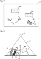
- FIG. 2 shows a monitoring situation in the monitoring area 12.
- the hedging task based on the sensor 10 is to detect the presence of humans, here simply defined as objects 28 of a certain minimum size and depending on their position and possibly other variables and the current machine state safety-oriented one initiate a defined reaction so that the safety of the people is guaranteed at all times.
- two danger points 26a-b are to be monitored, ie machine areas or machines, and currently four objects 28 are detected by the sensor 10 in its surroundings.
- Two of the objects 28 are, without the sensor 10 having to explicitly acquire this information, individual persons, another object 28 consists of two people fused together, either because they carry a workpiece together and are thus actually connected or because the segmentation is the two could not separate people.
- the unconnected arm of the person on the far left depending on the evaluation of his own further object, or he will, in particular according to the teaching of EP 3 200 122 A1 who slammed the person.
- the sensor 10 provides distance data so that a connected controller by reduced speed, an evasive rescheduling of the processes or, if necessary, timely stop the machines in the danger zones 26a-b protects the persons from injury.
- a hazard location 26a-b is a preferred modeling of the hazardous machinery 26.
- the hazard location 26a-b is a space area in which the machine 26 performs work movements in a respective period of time.
- the danger spot 26a-b may surround the machine 26 with some distance to allow sufficient play to the working movements.
- Several danger points 26a-b surround a plurality of machines 26 and / or a plurality of movable sections of a machine 26. Danger points 26a-b may be rigid and include all conceivable working movements.
- hazard areas 26a-b are respectively defined for subsections of the working movement which are used in a sequence corresponding to the process and which are smaller and better adapted.
- the control and evaluation unit 24 continuously calculates the shortest distance of the object 28 closest to a respective danger point 26a-b FIG. 2 arrows are drawn, which in the current situation of FIG. 2 represent the two shortest distances with respect to the two danger spots 26a-b.
- the shortest distance connects the next point of danger point 26a-b to the next point of the next object 28.
- the small object 28 at the bottom right exceeds the minimum size. Otherwise it would be ignored and instead output the distance to the two merged persons forming the second closest object 28.
- the shortest distance respectively determined last with respect to a danger point 26a-b is provided cyclically or acyclically at the secure interface 30.
- Typical output rates are several times per second, but it is also a rarer update conceivable, depending on the required and possible response time of the sensor 10.
- the next working step is re-planned depending on the shortest distance, so that the required safety distance between man and machine is maintained throughout the safe interface 30 connected higher-level control, in particular that of the machine 28.
- control and evaluation unit 24 also determines a speed of the object 28 at which the shortest distance was measured and outputs it at the shortest distance on the secure interface 30. This makes it possible to differentiate the hazard even better.
- the next object 28 is usually the most dangerous - or, strictly speaking, the most vulnerable.
- the safety margin that the machine 26 complies with when planning its movement may be designed for a maximum speed of human movement. Nevertheless, the machine's safety-related response to its environment is best adjusted when more information about the next object 28 and possibly other objects 28 is available.
- a dependency on the intrinsic state and the planned movement of the machine 26, in particular the position and speed of machine parts or even dangerous tool areas, is conceivable, such information preferably being provided by the machine control.
- control and evaluation unit 24 can output in addition to the shortest distance on the secure interface 30 so that they can be included in the safety consideration of the controller connected there.
- the speed of the next object 28 at which the shortest distance is measured has already been discussed.
- additional shortest distances to other objects 28 or separate object sections of the next object 28 are output, for example, another arm.
- a possible criterion here would be that there are more local distance minima in the same object, because the immediate neighboring points to the shortest distance are of no interest.
- the sensor 10 guarantees the monitoring of the five closest clearances per active danger location 26a-b.
- a sixth object and further objects or object sections are no longer taken into account, but additional information is conceivable such that there are more than five objects of the minimum size in the monitoring area 12.
- the connected controller can also be used for other future hazardous situations with other objects 28 as the next object 28 pre-plan.
- a plastic example is a still slightly further object 28 approaching a danger location 26a-b at high speed.
- next object 28 size of the next object 28, its position in the form of a center of gravity or of the next point, a direction of movement, an object envelope of an enveloping body surrounding the object 28 or a representation of the object 28 overall as an object cloud, 3D point cloud or 3D voxel representation.
- a safety application can be described as follows. This process is only an example. Initially, after suitable mounting of the sensor 10, for example in bird's eye view over the machine 26 to be secured, the danger points 26a-b are configured. Alternatively, a sensor composite is mounted in order to gain additional field of vision and / or further perspectives. The configuration itself is expediently done by a setter in a corresponding software tool, but also AR-like configurations directly in the workspace similar to the introductory mentioned EP 2 023 160 B1 are conceivable, where in this way protective fields are configured. It is conceivable to configure a further set of danger points 26a-b for each process step of the machine 26.
- the sensor 10 then detects the objects 28 in operation, which are located in the monitoring area 12, respectively.
- the recorded depth maps are filtered with the danger points 26a-b, which are not monitored themselves, and optionally with learned background objects. Small disturbing objects and imperfections in which no depth values can be detected are ignored.
- the control and evaluation unit 24 segmented in a manner not further explained here, the depth map to separate the objects 28. There are countless examples in the literature about such segmentations.
- each danger point 26a-b and each object 28 the distance is then determined.
- the distance between each object position, ie each object point, and each point of danger point 26a-b must be determined.
- more effective methods can be used, such as using envelopes, so that not every point really needs to be considered, as well as heuristics that some Quickly exclude objects 28 as inappropriate.
- a particularly effective method for finding the shortest distance is given.
- control and evaluation unit 24 determines, in addition to the shortest distance, further variables, such as the speed of the object 28 with the shortest distance or shortest distances to other objects 28.
- the shortest distance and any additional information are provided on the secure interface 28.
- a higher-level controller connected to the respective secure interfaces 30 reads out the data provided and fuses it. If the sensors 10 are initially calibrated to a common world coordinate system, this fusion is very simple since only the shortest distances per danger spot 26a-b provided locally by sensor 10 must be selected globally across all sensors 10.
- the higher-level controller or a machine controller connected thereto or directly to the secure interface 30 uses the shortest distances per danger spot 26a-b thus obtained to determine whether a rescheduling of the current work step or a future work step is required, so that the process runs optimally and the Safety is guaranteed. Only if necessary, the safety-related reaction consists in a shutdown of the machine 26th
- the determination of the shortest distances in the control and evaluation unit 24 is preferably carried out taking into account the projective geometry in 3D space.
- a 2D projection on the sensor image plane, a ground plane or an intermediate plane would be conceivable.
- FIG. 3 a schematic side view of the area monitored by the stereo camera 10 space area 12th
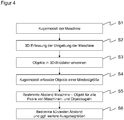
- FIG. 4 shows an example flowchart for evaluating the position of objects 28 to the monitoring machine 26 in rough steps. This is preferably done in each frame of the 3D image data acquisition or at least with a frequency that ensures a required safety-related response time.
- the machine 26 is represented for further evaluation for simplified handling by enveloping balls. These balls cover the machine 26 or at least those machine parts which form a source of danger to be monitored or the hazardous volume derived therefrom, ie the danger point 26a-b. In this case, a balance must be found between the expenditure for monitoring and the accuracy of the approximation for the number of spheres.
- the sphere representation is supplied to the control and evaluation unit 24 via an interface, for example, from other sensors or a controller of the machine 26, which knows or monitors their own motion.
- the space occupied by the machine 26, including its projection onto the image plane of the stereo camera 10 is masked out and not viewed, in order to avoid that the machine 26 itself is recognized as an object 28.
- a step S2 the spatial area 12 is then recorded by the stereo camera 10 in order to obtain 3D image data.
- the machine 26 is recognized in the 3D image data and derived therefrom a sphere representation, unless that data is otherwise made available. Then the sequence of steps S1 and S2 is preferably reversed.
- a step S3 objects 28 of the minimum size are captured in the 3D image data. They are then known with their 3D position, for example in the form of a detection card as described above.
- the objects 28 or their visible from the perspective of the stereo camera 10 surfaces are also modeled in a step S4 as a sphere.
- a sphere For example, each position in the detection map at which a distance value is entered and accordingly there an object 28 of the minimum size is detected, wrapped with a sphere of radius corresponding to the minimum size.
- a plurality of adjacent pixels in the detection map are populated with a distance value, so that nested spheres are formed there, which ultimately envelop the object as a whole. It is possible to eliminate in an intermediate step those balls that are covered by other balls and thus need not be evaluated.
- the stereo camera 10 then calculates in a step S5 which will be described with reference to FIGS FIGS. 5 to 7 is explained in more detail, the distances between the machine 26 and objects 28, in particular the shortest distance to use this for a safety-related response of the machine 26 can. Consequently, distances between the machine 26 and objects 28 representing balls must be calculated.
- the projective shadow that is to say the area hidden from view by the stereo camera 10 is a truncated cone for a sphere which is formed by rays emanating from the stereo camera 10.
- a step S6 the distances calculated for all pairs are evaluated together, in particular the shortest distance is determined as the minimum.
- the couples can also be restricted in advance. Obviously, the object 28 can be the far right in FIG. 3 do not have the shortest distance to the machine 26. It is possible to pre-set appropriate heuristics or procedures to limit the number of pairs and thus the effort.
- shortest distance One possible and in many cases particularly important output size is the shortest distance, because a typical safety consideration requires that a certain distance between machine 26 and object 28 is always maintained. But there may also be other or additional output sizes. For example, the n shortest distances to the machine 26 are calculated and output to evaluate multiple objects 28 or object areas. Similarly, it is possible, shortest distances to calculate and output to several sections of the machine 26 or more machines in parallel. Due to the spherical representation, there is no fundamental difference between a single machine 26 and several machines or danger spots. However, it is conceivable that different machine areas are treated differently, for example because of a degree of risk.
- the coordinates can also be output at a distance, that is to say the affected areas of the machine 26 or objects 28 including approximated or detected geometry in the 3D image data, the contact points of the distance line or the distance line itself.
- the speeds of the involved areas of the machine 26 and Objects 28 can be determined, for example, by object tracking, at least from a plurality of frames of the 3D detection. Depending on the subsequent safety consideration, such variables can be calculated and output in any combination that is relevant and available.
- FIG. 5 shows an exemplary flowchart with efficient single calculation steps for the calculation of the distance for a pair of balls with respective truncated cone. This can therefore be used as a concrete embodiment possibility of step S5 of in FIG. 4 be understood flowchart shown.
- a pair of balls for the machine 26 and an object 28 are selected, the distance of which is to be calculated taking into account the projective shadow 32, 34.
- the complete calculation remains geometrically correct, there is no approximation apart from unavoidable numerical inaccuracies.
- the respective enveloping spheres are converted into suitable world coordinates by means of a calibration of the 3D camera, in this case Cartesian coordinates.
- the balls are connected to a truncated cone to account for the projective shadow.
- a simplification for the further calculation takes place. It is checked which of the two partners of the pair, with respect to the respective center, is farther away from the stereo camera 10.
- the center of the closer partner is denoted by m
- the center of the further partner by p . Note that due to these definitions, m, p can no longer tell whether the machine 26 or object 28 is there, the geometric spacing problem is independent thereof.
- a step S13 at the further p, the cone is omitted.
- the projective shadows 32, 34 representing cones each arise from the perspective of the stereo camera 10 in projection and the distances are getting away from the stereo camera 10 so.
- the ball can be considered at the end very simply by subtracting its radius' of the calculated distance. In the nearer m, however, it remains with a ball that is connected to a truncated cone.
- FIG. 6 illustrates how to create a cutting plane through the three points c, m, p.
- the two normal vectors e 1 , e 2 thus span a Cartesian coordinate system within the section plane, with e 1 in the direction m and e 2 perpendicular thereto.
- FIG. 7 illustrates the situation in the cutting plane.
- the sphere around m becomes a circle around m 'of radius r
- the masking cone is defined by the tangents t 1 , t 2 to this circle through the origin c , which represent the conical surfaces in the section plane.
- tangents are considered.
- Be still ⁇ : m r the ratio of camera distance to radius r, ⁇ ⁇ 1.
- next point on the tangent to the point p or its parameterization along the tangent is needed.
- FIG. 7 For example, two different points p ' 1 , p' 2 corresponding to different possible positions of p are shown.
- the coordinate system p 'spanned by e 1 , e 2 always lies in the negative y / positive x-quadrant, which results from the order of the vectors in the cross product. This means, however, that always the descending tangent t 2 is closer.
- the tangent t 1 is preferably not considered, which facilitates the calculation in operation.
- a case distinction is now made.
- the shortest exists Distance to the tangent or to the circle.
- the tangent corresponds to the shadow 32, 34 and the circle of the machine 26 or the object 28 itself.
- the movement of the machine 26 is not completely free and dynamic, but largely known at set-up time. Then, the control and evaluation unit 24 does not have to re-look the sensor at runtime, but can predict the distances to many or all possible positions in the space region 12 in discretized form of 2D pixel addresses and depth value for a number of known configurations. This creates a look-up table in a configuration phase, which allows a very fast evaluation at runtime.
- the machine 26 is not taken into account with its Verdeckungskegel, for example, because the safety concept does not require.
- the machine 26 is then considered as a levitating ball, and the object 28 as a ball with Verdeckungskegel. If then all balls are the same size, can be expected more efficient with the squared distance, and the elaborate pulling of roots is eliminated.
- stereo camera 10 is just an exemplary sensor, and such a composite may also be inhomogeneous, ie have different sensor types.
- Each sensor determines the shortest distance for it with the projective masking that applies to it. The distances are evaluated in combination, for example by using the shortest distance from the group for safety-related evaluation.
Priority Applications (2)
| Application Number | Priority Date | Filing Date | Title |
|---|---|---|---|
| US16/007,000 US20190007659A1 (en) | 2017-06-28 | 2018-06-13 | Sensor for securing a machine |
| CN201810691295.XA CN109141373A (zh) | 2017-06-28 | 2018-06-28 | 用于防护机器的传感器 |
Applications Claiming Priority (1)
| Application Number | Priority Date | Filing Date | Title |
|---|---|---|---|
| EP17178332.7A EP3421189B1 (fr) | 2017-06-28 | 2017-06-28 | Procédé de surveillance d'une machine |
Publications (1)
| Publication Number | Publication Date |
|---|---|
| EP3421191A1 true EP3421191A1 (fr) | 2019-01-02 |
Family
ID=59276522
Family Applications (2)
| Application Number | Title | Priority Date | Filing Date |
|---|---|---|---|
| EP17178332.7A Active EP3421189B1 (fr) | 2017-06-28 | 2017-06-28 | Procédé de surveillance d'une machine |
| EP18170726.6A Withdrawn EP3421191A1 (fr) | 2017-06-28 | 2018-05-04 | Capteur de sécurisation d'une machine |
Family Applications Before (1)
| Application Number | Title | Priority Date | Filing Date |
|---|---|---|---|
| EP17178332.7A Active EP3421189B1 (fr) | 2017-06-28 | 2017-06-28 | Procédé de surveillance d'une machine |
Country Status (3)
| Country | Link |
|---|---|
| US (1) | US20190007659A1 (fr) |
| EP (2) | EP3421189B1 (fr) |
| CN (1) | CN109141373A (fr) |
Cited By (4)
| Publication number | Priority date | Publication date | Assignee | Title |
|---|---|---|---|---|
| WO2019113270A1 (fr) * | 2017-12-06 | 2019-06-13 | Illinois Tool Works Inc. | Procédé d'augmentation de zone de détection d'un système de détection d'intrusion vidéo à base d'ombre |
| DE102019206012A1 (de) * | 2019-04-26 | 2020-10-29 | Kuka Deutschland Gmbh | Verfahren und System zum Betreiben eines Roboters |
| EP3893145A1 (fr) | 2020-04-06 | 2021-10-13 | Sick Ag | Sécurisation d'un endroit dangereux |
| EP3916286A1 (fr) | 2020-05-29 | 2021-12-01 | Sick Ag | Capteur optoélectronique de sécurité et procédé de sécurisation d'une machine |
Families Citing this family (12)
| Publication number | Priority date | Publication date | Assignee | Title |
|---|---|---|---|---|
| CN106406312B (zh) * | 2016-10-14 | 2017-12-26 | 平安科技(深圳)有限公司 | 导览机器人及其移动区域标定方法 |
| US20190034735A1 (en) * | 2017-07-25 | 2019-01-31 | Motionloft, Inc. | Object detection sensors and systems |
| EP3437804A1 (fr) * | 2017-08-02 | 2019-02-06 | ABB Schweiz AG | Procédé de commande de robot |
| US10366531B2 (en) * | 2017-10-24 | 2019-07-30 | Lowe's Companies, Inc. | Robot motion planning for photogrammetry |
| US9990767B1 (en) | 2017-10-24 | 2018-06-05 | Lowe's Companies, Inc. | Generation of 3D models using stochastic shape distribution |
| JP6680752B2 (ja) * | 2017-11-28 | 2020-04-15 | ファナック株式会社 | ロボットの速度を制限する制御装置 |
| EP3709106B1 (fr) * | 2019-03-11 | 2021-01-06 | Sick Ag | Mise en sécurité d'une machine |
| CN112991356B (zh) * | 2019-12-12 | 2023-08-01 | 中国科学院沈阳自动化研究所 | 机械臂在复杂环境下的快速分割方法 |
| CN111203875B (zh) * | 2020-01-07 | 2022-08-09 | 重庆邮电大学 | 一种机械臂碰撞安全等级检测系统 |
| CN113740355B (zh) * | 2020-05-29 | 2023-06-20 | 清华大学 | 一种射线检测机器人的边界防护方法及系统 |
| CN113566723B (zh) * | 2021-08-09 | 2023-03-21 | 中国商用飞机有限责任公司北京民用飞机技术研究中心 | 一种零件间隙与干涉检查方法及其系统 |
| US20230230379A1 (en) * | 2022-01-19 | 2023-07-20 | Target Brands, Inc. | Safety compliance system and method |
Citations (2)
| Publication number | Priority date | Publication date | Assignee | Title |
|---|---|---|---|---|
| EP2386876A1 (fr) * | 2010-05-04 | 2011-11-16 | Sick AG | Capteur de sécurité optoélectronique mesurant l'éloignement et procédé de surveillance d'une zone de surveillance |
| EP2947604A1 (fr) * | 2014-05-19 | 2015-11-25 | Rockwell Automation Technologies, Inc. | Intégration de contrôle de la zone optique avec commande de machines industrielles |
Family Cites Families (14)
| Publication number | Priority date | Publication date | Assignee | Title |
|---|---|---|---|---|
| DE10152543A1 (de) * | 2001-10-24 | 2003-05-08 | Sick Ag | Verfahren und Vorrichtung zum Steuern einer sicherheitsrelevanten Funktion einer Maschine |
| DE102004041821A1 (de) * | 2004-08-27 | 2006-03-16 | Abb Research Ltd. | Vorrichtung und Verfahren zur Sicherung eines maschinell gesteuerten Handhabungsgerätes |
| CN100562877C (zh) * | 2006-04-24 | 2009-11-25 | 日产自动车株式会社 | 可照射区域识别方法和装置以及移动路径设定方法 |
| DE102006057605A1 (de) * | 2006-11-24 | 2008-06-05 | Pilz Gmbh & Co. Kg | Verfahren und Vorrichtung zum Überwachen eines dreidimensionalen Raumbereichs |
| CN104257394B (zh) * | 2007-12-21 | 2017-04-12 | 科宁公司 | 锥光束ct成像和图像引导程序的方法和装置 |
| DE102009006256B4 (de) | 2009-01-27 | 2019-01-03 | Deutsches Forschungszentrum für künstliche Intelligenz GmbH | Verfahren zur Vermeidung von Kollisionen gesteuert beweglicher Teile einer Anlage |
| EP2641236A1 (fr) * | 2010-11-17 | 2013-09-25 | Omron Scientific Technologies, Inc. | Procédé et appareil de surveillance de zones |
| DE202010013139U1 (de) * | 2010-12-16 | 2012-03-19 | Sick Ag | Schnittstellenadapter für einen elektronischen Sensor |
| CN102778223A (zh) * | 2012-06-07 | 2012-11-14 | 沈阳理工大学 | 基于车牌合作目标和单目摄像机的汽车防撞预警方法 |
| DE102013104265A1 (de) * | 2013-04-26 | 2014-10-30 | Pilz Gmbh & Co. Kg | Vorrichtung und Verfahren zum Absichern einer automatisiert arbeitenden Maschine |
| EP2819109B1 (fr) | 2013-06-28 | 2015-05-27 | Sick Ag | Capteur optoélectronique 3D et procédé de reconnaissance d'objets |
| CN104330025B (zh) * | 2014-10-22 | 2016-12-07 | 中国计量学院 | 工业机器人位姿检测装置 |
| US9892611B1 (en) * | 2015-06-01 | 2018-02-13 | Cerner Innovation, Inc. | Method for determining whether an individual enters a prescribed virtual zone using skeletal tracking and 3D blob detection |
| CN106373156A (zh) * | 2015-07-20 | 2017-02-01 | 小米科技有限责任公司 | 通过图像确定空间参数的方法、装置及终端设备 |
-
2017
- 2017-06-28 EP EP17178332.7A patent/EP3421189B1/fr active Active
-
2018
- 2018-05-04 EP EP18170726.6A patent/EP3421191A1/fr not_active Withdrawn
- 2018-06-13 US US16/007,000 patent/US20190007659A1/en not_active Abandoned
- 2018-06-28 CN CN201810691295.XA patent/CN109141373A/zh active Pending
Patent Citations (2)
| Publication number | Priority date | Publication date | Assignee | Title |
|---|---|---|---|---|
| EP2386876A1 (fr) * | 2010-05-04 | 2011-11-16 | Sick AG | Capteur de sécurité optoélectronique mesurant l'éloignement et procédé de surveillance d'une zone de surveillance |
| EP2947604A1 (fr) * | 2014-05-19 | 2015-11-25 | Rockwell Automation Technologies, Inc. | Intégration de contrôle de la zone optique avec commande de machines industrielles |
Non-Patent Citations (3)
| Title |
|---|
| FLACCO FABRIZIO ET AL: "A Depth Space Approach for Evaluating Distance to Objects", JOURNAL OF INTELLIGENT AND ROBOTIC SYSTEMS, KLUWER DORDRECHT, NL, vol. 80, no. 1, 24 October 2014 (2014-10-24), pages 7 - 22, XP035913842, ISSN: 0921-0296, [retrieved on 20141024], DOI: 10.1007/S10846-014-0146-2 * |
| MISEIKIS JUSTINAS ET AL: "Multi 3D camera mapping for predictive and reflexive robot manipulator trajectory estimation", 2016 IEEE SYMPOSIUM SERIES ON COMPUTATIONAL INTELLIGENCE (SSCI), IEEE, 6 December 2016 (2016-12-06), pages 1 - 8, XP033066633, DOI: 10.1109/SSCI.2016.7850237 * |
| ZUBE ANGELIKA: "Combined workspace monitoring and collision avoidance for mobile manipulators", 2015 IEEE 20TH CONFERENCE ON EMERGING TECHNOLOGIES & FACTORY AUTOMATION (ETFA), IEEE, 8 September 2015 (2015-09-08), pages 1 - 8, XP032797449, DOI: 10.1109/ETFA.2015.7301526 * |
Cited By (6)
| Publication number | Priority date | Publication date | Assignee | Title |
|---|---|---|---|---|
| WO2019113270A1 (fr) * | 2017-12-06 | 2019-06-13 | Illinois Tool Works Inc. | Procédé d'augmentation de zone de détection d'un système de détection d'intrusion vidéo à base d'ombre |
| US10650646B2 (en) | 2017-12-06 | 2020-05-12 | Illinois Tool Works Inc. | Method of increasing detection zone of a shadow-based video intrusion detection system |
| DE102019206012A1 (de) * | 2019-04-26 | 2020-10-29 | Kuka Deutschland Gmbh | Verfahren und System zum Betreiben eines Roboters |
| EP3893145A1 (fr) | 2020-04-06 | 2021-10-13 | Sick Ag | Sécurisation d'un endroit dangereux |
| EP3916286A1 (fr) | 2020-05-29 | 2021-12-01 | Sick Ag | Capteur optoélectronique de sécurité et procédé de sécurisation d'une machine |
| DE102020114488B3 (de) | 2020-05-29 | 2021-12-02 | Sick Ag | Optoelektronischer Sicherheitssensor und Verfahren zur Absicherung einer Maschine |
Also Published As
| Publication number | Publication date |
|---|---|
| EP3421189A1 (fr) | 2019-01-02 |
| US20190007659A1 (en) | 2019-01-03 |
| EP3421189B1 (fr) | 2019-05-22 |
| CN109141373A (zh) | 2019-01-04 |
Similar Documents
| Publication | Publication Date | Title |
|---|---|---|
| EP3421191A1 (fr) | Capteur de sécurisation d'une machine | |
| EP3011225B1 (fr) | Dispositif et procédé pour protéger une machine fonctionnant de manière automatisée | |
| EP2275990B1 (fr) | Capteur 3D | |
| EP3611422B1 (fr) | Dispositif capteur et procédé de sécurisation d'une zone de surveillance | |
| EP3578320B1 (fr) | Configurer un endroit dangereux surveillé par un capteur tridimensionnel | |
| EP2461181B1 (fr) | Dispositif de détection destiné à l'identification d'objet | |
| DE102010037744B3 (de) | Optoelektronischer Sensor | |
| DE102007007576B4 (de) | Verfahren und Vorrichtung zum Sichern eines Arbeitsraums | |
| EP2835973B1 (fr) | Caméra 3D et un procédé de capture de données d'image tridimensionnelles | |
| EP2386876B1 (fr) | Capteur de sécurité optoélectronique mesurant l'éloignement et procédé de surveillance d'une zone de surveillance | |
| EP3578319B1 (fr) | Procédé de sécurisation d'un endroit dangereux | |
| DE102017111885B4 (de) | Verfahren und System zum Überwachen einer Maschine | |
| EP2819109B1 (fr) | Capteur optoélectronique 3D et procédé de reconnaissance d'objets | |
| EP3573021A1 (fr) | Visualisation de données d'image tridimensionnelle | |
| EP3572971B1 (fr) | Protection d'une zone de surveillance à au moins une machine | |
| DE102016222245A1 (de) | Einrichtung und Verfahren zur Einwirkung auf Gegenstände | |
| DE102018116371B4 (de) | 3D-Sensor und Verfahren zum Überwachen eines Überwachungsbereichs | |
| EP3893145B1 (fr) | Sécurisation d'un endroit dangereux | |
| EP2818824B1 (fr) | Appareil comprenant un capteur optoélectronique 3D et procédé de réconaissance d'objets | |
| DE102019127826B4 (de) | Sicherer optoelektronischer Sensor und Verfahren zum Absichern eines Überwachungsbereichs | |
| DE102020127670B4 (de) | Absichern eines beweglichen Maschinenteils | |
| DE202018103869U1 (de) | 3D-Sensor zum Überwachen eines Überwachungsbereichs | |
| DE202015102019U1 (de) | Kamera zur Aufnahme von Bildern eines Erfassungsbereichs | |
| EP4131139A1 (fr) | Dispositif capteur et procédé de sécurisation d'une zone de surveillance | |
| DE202016103603U1 (de) | 3D-Kamera |
Legal Events
| Date | Code | Title | Description |
|---|---|---|---|
| PUAI | Public reference made under article 153(3) epc to a published international application that has entered the european phase |
Free format text: ORIGINAL CODE: 0009012 |
|
| STAA | Information on the status of an ep patent application or granted ep patent |
Free format text: STATUS: THE APPLICATION HAS BEEN PUBLISHED |
|
| AK | Designated contracting states |
Kind code of ref document: A1 Designated state(s): AL AT BE BG CH CY CZ DE DK EE ES FI FR GB GR HR HU IE IS IT LI LT LU LV MC MK MT NL NO PL PT RO RS SE SI SK SM TR |
|
| AX | Request for extension of the european patent |
Extension state: BA ME |
|
| STAA | Information on the status of an ep patent application or granted ep patent |
Free format text: STATUS: REQUEST FOR EXAMINATION WAS MADE |
|
| 17P | Request for examination filed |
Effective date: 20190315 |
|
| RBV | Designated contracting states (corrected) |
Designated state(s): AL AT BE BG CH CY CZ DE DK EE ES FI FR GB GR HR HU IE IS IT LI LT LU LV MC MK MT NL NO PL PT RO RS SE SI SK SM TR |
|
| STAA | Information on the status of an ep patent application or granted ep patent |
Free format text: STATUS: EXAMINATION IS IN PROGRESS |
|
| 17Q | First examination report despatched |
Effective date: 20190605 |
|
| STAA | Information on the status of an ep patent application or granted ep patent |
Free format text: STATUS: THE APPLICATION HAS BEEN WITHDRAWN |
|
| RAP1 | Party data changed (applicant data changed or rights of an application transferred) |
Owner name: SICK AG |
|
| 18W | Application withdrawn |
Effective date: 20200206 |