EP3421189A1 - Procédé de surveillance d'une machine - Google Patents
Procédé de surveillance d'une machine Download PDFInfo
- Publication number
- EP3421189A1 EP3421189A1 EP17178332.7A EP17178332A EP3421189A1 EP 3421189 A1 EP3421189 A1 EP 3421189A1 EP 17178332 A EP17178332 A EP 17178332A EP 3421189 A1 EP3421189 A1 EP 3421189A1
- Authority
- EP
- European Patent Office
- Prior art keywords
- machine
- distance
- objects
- ball
- determined
- Prior art date
- Legal status (The legal status is an assumption and is not a legal conclusion. Google has not performed a legal analysis and makes no representation as to the accuracy of the status listed.)
- Granted
Links
Images


Classifications
-
- G—PHYSICS
- G01—MEASURING; TESTING
- G01C—MEASURING DISTANCES, LEVELS OR BEARINGS; SURVEYING; NAVIGATION; GYROSCOPIC INSTRUMENTS; PHOTOGRAMMETRY OR VIDEOGRAMMETRY
- G01C11/00—Photogrammetry or videogrammetry, e.g. stereogrammetry; Photographic surveying
- G01C11/04—Interpretation of pictures
- G01C11/30—Interpretation of pictures by triangulation
-
- H—ELECTRICITY
- H04—ELECTRIC COMMUNICATION TECHNIQUE
- H04N—PICTORIAL COMMUNICATION, e.g. TELEVISION
- H04N7/00—Television systems
- H04N7/18—Closed-circuit television [CCTV] systems, i.e. systems in which the video signal is not broadcast
- H04N7/183—Closed-circuit television [CCTV] systems, i.e. systems in which the video signal is not broadcast for receiving images from a single remote source
-
- B—PERFORMING OPERATIONS; TRANSPORTING
- B25—HAND TOOLS; PORTABLE POWER-DRIVEN TOOLS; MANIPULATORS
- B25J—MANIPULATORS; CHAMBERS PROVIDED WITH MANIPULATION DEVICES
- B25J9/00—Programme-controlled manipulators
- B25J9/16—Programme controls
- B25J9/1674—Programme controls characterised by safety, monitoring, diagnostic
- B25J9/1676—Avoiding collision or forbidden zones
-
- G—PHYSICS
- G01—MEASURING; TESTING
- G01B—MEASURING LENGTH, THICKNESS OR SIMILAR LINEAR DIMENSIONS; MEASURING ANGLES; MEASURING AREAS; MEASURING IRREGULARITIES OF SURFACES OR CONTOURS
- G01B11/00—Measuring arrangements characterised by the use of optical techniques
- G01B11/14—Measuring arrangements characterised by the use of optical techniques for measuring distance or clearance between spaced objects or spaced apertures
-
- G—PHYSICS
- G01—MEASURING; TESTING
- G01C—MEASURING DISTANCES, LEVELS OR BEARINGS; SURVEYING; NAVIGATION; GYROSCOPIC INSTRUMENTS; PHOTOGRAMMETRY OR VIDEOGRAMMETRY
- G01C11/00—Photogrammetry or videogrammetry, e.g. stereogrammetry; Photographic surveying
- G01C11/02—Picture taking arrangements specially adapted for photogrammetry or photographic surveying, e.g. controlling overlapping of pictures
- G01C11/025—Picture taking arrangements specially adapted for photogrammetry or photographic surveying, e.g. controlling overlapping of pictures by scanning the object
-
- G—PHYSICS
- G06—COMPUTING; CALCULATING OR COUNTING
- G06T—IMAGE DATA PROCESSING OR GENERATION, IN GENERAL
- G06T7/00—Image analysis
- G06T7/50—Depth or shape recovery
- G06T7/55—Depth or shape recovery from multiple images
- G06T7/593—Depth or shape recovery from multiple images from stereo images
-
- G—PHYSICS
- G06—COMPUTING; CALCULATING OR COUNTING
- G06T—IMAGE DATA PROCESSING OR GENERATION, IN GENERAL
- G06T7/00—Image analysis
- G06T7/70—Determining position or orientation of objects or cameras
- G06T7/73—Determining position or orientation of objects or cameras using feature-based methods
-
- G—PHYSICS
- G06—COMPUTING; CALCULATING OR COUNTING
- G06V—IMAGE OR VIDEO RECOGNITION OR UNDERSTANDING
- G06V20/00—Scenes; Scene-specific elements
- G06V20/50—Context or environment of the image
- G06V20/52—Surveillance or monitoring of activities, e.g. for recognising suspicious objects
-
- G—PHYSICS
- G06—COMPUTING; CALCULATING OR COUNTING
- G06V—IMAGE OR VIDEO RECOGNITION OR UNDERSTANDING
- G06V20/00—Scenes; Scene-specific elements
- G06V20/60—Type of objects
- G06V20/64—Three-dimensional objects
-
- H—ELECTRICITY
- H04—ELECTRIC COMMUNICATION TECHNIQUE
- H04N—PICTORIAL COMMUNICATION, e.g. TELEVISION
- H04N13/00—Stereoscopic video systems; Multi-view video systems; Details thereof
- H04N13/20—Image signal generators
- H04N13/204—Image signal generators using stereoscopic image cameras
- H04N13/239—Image signal generators using stereoscopic image cameras using two 2D image sensors having a relative position equal to or related to the interocular distance
-
- H—ELECTRICITY
- H04—ELECTRIC COMMUNICATION TECHNIQUE
- H04N—PICTORIAL COMMUNICATION, e.g. TELEVISION
- H04N13/00—Stereoscopic video systems; Multi-view video systems; Details thereof
- H04N13/20—Image signal generators
- H04N13/271—Image signal generators wherein the generated image signals comprise depth maps or disparity maps
-
- H—ELECTRICITY
- H04—ELECTRIC COMMUNICATION TECHNIQUE
- H04N—PICTORIAL COMMUNICATION, e.g. TELEVISION
- H04N13/00—Stereoscopic video systems; Multi-view video systems; Details thereof
- H04N13/20—Image signal generators
- H04N13/296—Synchronisation thereof; Control thereof
-
- G—PHYSICS
- G01—MEASURING; TESTING
- G01S—RADIO DIRECTION-FINDING; RADIO NAVIGATION; DETERMINING DISTANCE OR VELOCITY BY USE OF RADIO WAVES; LOCATING OR PRESENCE-DETECTING BY USE OF THE REFLECTION OR RERADIATION OF RADIO WAVES; ANALOGOUS ARRANGEMENTS USING OTHER WAVES
- G01S17/00—Systems using the reflection or reradiation of electromagnetic waves other than radio waves, e.g. lidar systems
- G01S17/88—Lidar systems specially adapted for specific applications
- G01S17/89—Lidar systems specially adapted for specific applications for mapping or imaging
-
- G—PHYSICS
- G05—CONTROLLING; REGULATING
- G05B—CONTROL OR REGULATING SYSTEMS IN GENERAL; FUNCTIONAL ELEMENTS OF SUCH SYSTEMS; MONITORING OR TESTING ARRANGEMENTS FOR SUCH SYSTEMS OR ELEMENTS
- G05B2219/00—Program-control systems
- G05B2219/30—Nc systems
- G05B2219/37—Measurements
- G05B2219/37571—Camera detecting reflected light from laser
-
- G—PHYSICS
- G05—CONTROLLING; REGULATING
- G05B—CONTROL OR REGULATING SYSTEMS IN GENERAL; FUNCTIONAL ELEMENTS OF SUCH SYSTEMS; MONITORING OR TESTING ARRANGEMENTS FOR SUCH SYSTEMS OR ELEMENTS
- G05B2219/00—Program-control systems
- G05B2219/30—Nc systems
- G05B2219/40—Robotics, robotics mapping to robotics vision
- G05B2219/40202—Human robot coexistence
-
- G—PHYSICS
- G05—CONTROLLING; REGULATING
- G05B—CONTROL OR REGULATING SYSTEMS IN GENERAL; FUNCTIONAL ELEMENTS OF SUCH SYSTEMS; MONITORING OR TESTING ARRANGEMENTS FOR SUCH SYSTEMS OR ELEMENTS
- G05B2219/00—Program-control systems
- G05B2219/30—Nc systems
- G05B2219/40—Robotics, robotics mapping to robotics vision
- G05B2219/40203—Detect position of operator, create non material barrier to protect operator
-
- G—PHYSICS
- G06—COMPUTING; CALCULATING OR COUNTING
- G06T—IMAGE DATA PROCESSING OR GENERATION, IN GENERAL
- G06T2207/00—Indexing scheme for image analysis or image enhancement
- G06T2207/10—Image acquisition modality
- G06T2207/10028—Range image; Depth image; 3D point clouds
-
- G—PHYSICS
- G06—COMPUTING; CALCULATING OR COUNTING
- G06T—IMAGE DATA PROCESSING OR GENERATION, IN GENERAL
- G06T2207/00—Indexing scheme for image analysis or image enhancement
- G06T2207/30—Subject of image; Context of image processing
- G06T2207/30196—Human being; Person
-
- G—PHYSICS
- G06—COMPUTING; CALCULATING OR COUNTING
- G06T—IMAGE DATA PROCESSING OR GENERATION, IN GENERAL
- G06T2207/00—Indexing scheme for image analysis or image enhancement
- G06T2207/30—Subject of image; Context of image processing
- G06T2207/30232—Surveillance
Definitions
- the invention relates to a method for monitoring a machine according to the preamble of claim 1.
- the primary goal of safety technology is to protect people from sources of danger such as those in industrial environments.
- the machine is monitored by means of sensors, and if there is a situation in which a person threatens to come dangerously close to the machine, an appropriate safeguard is taken.
- a common protection concept envisages that protective fields are configured which must not be entered by operating personnel during operation of the machine. If the sensor detects an inadmissible protective field intervention, for example a leg of an operator, it triggers a safety-related stop of the machine.
- Alternatives to protective fields are also known, for instance to ensure that a minimum distance dependent on the relative movement is maintained between machine and person ("speed and separation monitoring").
- 3D sensors are used for the monitoring. These include 3D cameras in various technologies, such as stereoscopy, triangulation, light transit time, with evaluation of the disturbance of passive two-dimensional patterns or projected illumination patterns. Such 3D sensors, in contrast to a conventional two-dimensional camera, record images which contain a distance value in their pixels. This depth-resolved or three-dimensional image data is also referred to as a depth map. Also known are scanning in two or all three directions laser scanner, which also detect three-dimensional image data on the respective scanning angle and the measured distance. The higher device and evaluation effort compared to a two-dimensional image capture For the generation of three-dimensional image data is justified in many applications by the additional information.
- Sensors used in safety technology must work extremely reliably and therefore meet high safety requirements, for example EN13849 for machine safety and IEC61496 or EN61496 for contactless protective devices (ESPE).
- ESE contactless protective devices
- a number of measures must be taken, such as safe electronic evaluation by means of redundant, diverse electronics, function monitoring or especially monitoring of the contamination of optical components.
- arXiv preprint arXiv: 1610.03646 (2016 ) a collision map in the voxel space is formed from the data of several sensors, if necessary, a robot evades. Again, the projective coverage is disregarded.
- This object is achieved by a method for monitoring a machine according to claim 1 or a 3D sensor according to claim 15.
- 3D image data of an environment of the machine is acquired.
- the perspective of the shot is designated by an origin position, which is, for example, the position of a monitoring 3D sensor.
- the 3D image data is evaluated to find the positions of objects in it.
- the objects have in particular a minimum size that corresponds to a desired protection, for example by 10 mm for finger protection or in the range of 30-80mm for the protection of extremities.
- the minimum size can not be smaller than the detection capability, which in turn depends on the optical resolution, but also on the evaluation method for finding the objects in the 3D image data.
- the invention is based on the basic idea of determining the distance between objects and machine for evaluating the danger by or for the detected objects and thereby to include the projective occlusion.
- the shortest distance is searched, because that means the greatest danger.
- other factors play a role, such as relative speeds or, for example, the actual danger from a machine part where a hot or pointed tool can be handled differently than a padded, lightweight robot arm.
- the machine part to which the distance is determined does not necessarily have to be directly the measured, physical machine part. It may be useful to surround it with a buffer, for example, a larger and future stay area including movement options and response time or guaranteed "safe zones" of a robot.
- a captured object When capturing 3D image data from an origin position, a captured object obscures the area behind it.
- the shaded area corresponds to the projection of the object from the original position into the distance and is therefore called a projective shadow. It can not be decided if there is another object hidden there. Therefore, according to the invention, the projective shadow as a precaution to the detected object and / or the machine part struck, so treated as if the projective shadow part of the object. At first glance, it seems necessary to strike the projective shadow on both the object and the machine part. It is also possible to do so. However, as explained later, it is sufficient to consider the projective shadow only for either the machine part or the object.
- the invention has the advantage that, by taking into account the occlusion, a safe recognition of danger and in particular of persons is made possible.
- the method efficiently calculates distances including occlusion in an optimized flow, enables cost-effective implementation on a CPU, embedded hardware, application-specific integrated circuit (ASIC) or field programmable gate array (FPGA), or combinations thereof, and is easy to parallelize. since the calculations for different pairs of machine parts and objects or sub-areas of them are independent of each other.
- the calculation is geometrically exact except for unavoidable numerical errors, and it is ensured that the distance is at best slightly underestimated, but never overestimated. Thus, an error has at most a low impact on availability and does not impair security.
- the positions of machine parts are preferably determined in the form of at least one machine covering the ball. This leads to a certain underestimation of distances, since the machine contour is not exactly replicated, but facilitates the evaluation quite considerably. With a larger number of balls also different radii, the machine can be covered with virtually any small buffer zones. It is not mandatory to represent the entire machine by bullets, but only the dangerous machine parts. Immovable machine parts, structurally inaccessible areas, a slowly moving, light or soft machine part need not necessarily be secured. Obtaining a suitable sphere representation is not the subject of this invention. It can, for example, be read in directly by a machine or robot controller which knows or monitors the proper movement of the machine. It is also conceivable to identify the machine in the 3D image data and to suitably cover it with balls. If the machine movement is reproducible, the ball representation can be obtained in a preparatory step.
- the objects are preferably modeled as spheres with center at the position of the object and radius corresponding to the minimum size. If the object exceeds the minimum size in one dimension, several such balls are formed accordingly.
- the object-side representation of the preferred ball representation of the machine corresponds and allows a simplified evaluation.
- the projective shadow is preferably modeled as a cone.
- the tip of the cone is the position of the object or machine part, and the conical surface is created by projective extension of rays that start in the original position.
- the projective shadow is a truncated cone that is closed up towards the origin position by the sphere, and the truncated cone is the exact associated projective shadow.
- the distance preferably only the object whose projective shadow is added when the object is closer to the original position than the machine part, and conversely only the machine part whose projective shadow struck, when the machine part is closer to the original position.
- the projective shadow is therefore considered within a pair of object and machine part only for the closer partner. This is not an approximation, but a reduction of the effort.
- the unconsidered shadow always lies, as is apparent from geometrical considerations, at a greater distance.
- the respectively closer partner of a pair of machine part and object in the form of a first ball together with cone as projective shadow and the further partner as second ball are preferably modeled. It refers more closely and further to the original position.
- the result is also correct if the distant partner is also modeled with a cone, but the determination of the distance does not become more exact and unnecessarily time-consuming.
- the distance determination is preferably carried out in a sectional plane which is defined by the original position, the center of the first ball and the center of the second ball.
- the three points define a clear level in which all relevant information is still presentable.
- the determination of the distance becomes a merely two-dimensional and much easier to handle problem.
- the center of the first sphere and the center of the second sphere are preferably projected into the cutting plane, while the origin position without computation also forms the origin of coordinates for computational simplification.
- a tangent from the original position to a projection of the first ball into the sectional plane is preferably considered.
- the tangent is considered, so the calculations are based on the model idea of such a tangent, but an actual calculation or even representation of the tangent is not required.
- the projection of the first sphere results in a circle. Actually, there are two tangents through the origin position to this circle, which both can be viewed, but need not, because as explained in the next paragraph, only one tangent for the distance in question comes into question.
- the closer and farther tangents are immediately distinguishable on the basis of their slope behavior in the selected section plane; in particular, the closer tangent in the concrete coordinates of the embodiment explained below always has a negative slope and the further tangent has a positive slope.
- the center of the second sphere on the tangent on the basis of the solder is distinguished from the center of the second sphere on the tangent on the basis of the solder, whether the shortest distance to the first sphere or to its projective shadow exists. It is therefore made a case distinction, whether the object or machine part modeling ball itself or its projective shadow the shortest distance.
- the distinguishing criterion is whether the foot of the solder lies behind or in front of the point of contact of the tangent to the circle. If, according to the case distinction, the ball itself is decisive, the distance of the centers is formed by subtracting the radii. Is it the projective Shadow, so the distance between the center of the second ball and the already known base of the solder is used on the tangent.
- the distance is preferably determined for all pairs of machine parts and objects and the shortest distance as the minimum of these distances.
- the respective calculations for the different pairs may be performed sequentially and / or in parallel. It is also possible to restrict the pairs in advance. Then the pool of all couples is formed by the restricted couple. With a well-known perspective of capturing the 3D image data, it may be possible to decide very quickly for objects without concrete calculations that they and their projective shadows can not be considered objects with the shortest distance to the machine.
- At least one of the following variables is determined: n pairs of machine parts and objects with the shortest distance, m nearest objects to a machine part or vice versa machine parts to an object, the 3D positions between which the distances exist, further object data of an object with the shortest distance , in particular its position, speed and / or contour.
- This can be a more complex assessment of the environment of the machine as only by the shortest distance.
- the machine is safeguarded when a determined distance falls below a safety distance.
- a safety distance examples of protection are an emergency stop, a braking, a dodge or a move to a safe position.
- a fixed minimum distance which is determined, for example, under worst-case assumptions at speeds or from known or measured trailing paths.
- dynamic safety distances among other things, depending on the current speed of the machine and the object.
- data can be obtained from the machine control or image analysis with object tracking and also via other sensors.
- the 3D image data are preferably determined from at least two original positions, wherein in overlapping regions distances with the different projective shadows are first determined separately and then a common shortest distance is found.
- the invention takes into account the occlusion in a safe and appropriate manner, but the monitoring restriction by Do not pick up obscurity.
- the projective shadows disappear after joint evaluation or at least become much smaller.
- the distances are first determined separately in the 3D image data from different original positions, and only then are the shortest distances sought. In this way, the evaluation remains decoupled, parallelizable and easy to handle.
- 3D image data could also be merged earlier in the processing chain, thereby directly eliminating or reducing the projective shadows. However, this is much more complex and not simply a continuation of the method according to the invention to several 3D image recordings from different perspectives.
- a 3D sensor according to the invention for monitoring a machine has a sensor head for detecting 3D image data of an environment of the machine and an evaluation unit which is designed to evaluate the 3D image data using a method according to the invention and thus a distance between the machine and objects in the vicinity of the machine.
- 3D sensors include 3D cameras and 3D scanners.
- a 3D camera can use any known technique, such as a triangulation principle in which two camera images of a moving or stereo camera correlate with each other or a camera image and a known projection pattern and disparities are estimated, or a light transit time principle with direct transit time measurement of light signals or phase measurement.
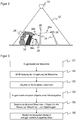
- FIG. 1 shows in a schematic three-dimensional representation of the general structure of a stereo camera 10 for receiving a depth map.
- the stereo camera 10 is just one example in which the detection of 3D image data is explained. Also conceivable would be, inter alia, the other mentioned 3D cameras with determination of the light transit time or an evaluation of the disturbance of passive two-dimensional pattern or of projected illumination patterns and laser scanners.
- two camera modules 14a, 14b are mounted at a known, fixed distance from one another and record images of the spatial region 12 in each case.
- an image sensor 16a, 16b is provided, usually a matrix-shaped recording chip, which receives a rectangular pixel image, for example a CCD or a CMOS sensor.
- the two image sensors 16a, 16b together form a 3D image sensor for detecting a depth map.
- the image sensors 16a, 16b are each assigned an objective 18a, 18b with imaging optics, which in practice can be realized as any known imaging objective.
- the maximum viewing angle of these optics is in FIG. 1 represented by dashed lines, each forming a reformpyramide 20a, 20b.
- a lighting unit 22 is provided to illuminate the space area 12 with a structured pattern.
- the stereoscopic camera shown is therefore designed for active stereoscopy, in which the pattern also imprints a contrast that can be evaluated anywhere in a structureless scene.
- no or a homogeneous illumination is provided in order to evaluate the natural object structures in the spatial region 12, but this regularly leads to additional image errors.
- a control and evaluation unit 24 is connected to the two image sensors 16a, 16b and the illumination unit 22.
- the control and evaluation unit 24 can in Various hardware may be implemented, such as digital devices such as microprocessors, Application Specific Integrated Circuits (ASICs), field programmable gate arrays (FPGAs), graphics processing units (GPUs), or hybrids thereof, which can be arbitrarily distributed to internal and external components, including external components can also be integrated via network or a cloud, as long as latencies can be mastered or tolerated. Since the generation of the depth map and its evaluation are very computationally intensive, an at least partially parallel architecture is preferably formed.
- the control and evaluation unit 24 generates the structured illumination pattern with the aid of the illumination unit 22 and receives image data of the image sensors 16a, 16b. From this image data, it calculates the 3D image data or the depth map of the spatial region 12 with the aid of a stereoscopic disparity estimation.
- the entire detectable spatial region 12 or also working region can be restricted via a configuration, for example to hide disturbing or unnecessary regions.
- An important safety application of the stereo camera 10 is the monitoring of a machine 26, which in the FIG. 1 symbolized by a robot.
- the machine 26 may also be much more complex than shown, consist of many parts, or even actually be an assembly of multiple machines, such as multiple robots or robotic arms.
- the control and evaluation unit 24 checks whether an object 28, represented as a person, is in a dangerous position with respect to the machine 26, which may depend on further conditions such as the speeds or the nature of the object and machine area of the imminent collision , In the event of danger, a safety-related safety signal is output via an output 30 (OSSD, Output Signal Switching Device), for example to stop, decelerate or dodge the machine 26.
- OSD Output Signal Switching Device
- a control signal may be output to the machine 26 or measurement results such as a minimum distance of an object to the machine 26, either directly to the machine 26 or to an intermediate station such as a secure controller.
- the stereo camera 10 is preferably failsafe in the sense of safety standards such as the initially mentioned.
- control and evaluation unit 24 enables position and distance monitoring, for example for a Human-robot collaboration taking into account DIN EN ISO 10218 or ISO / TS 15066.
- the starting point are the positions of the machine parts of the machine 26, at least insofar as they are safety-relevant, if appropriate on the basis of reaction and stopping time or other criteria extended to a dangerous volume, as well as the detected by the stereo camera 10 objects 28.
- the latter is for example in the form of a 2D detection card whose pixels at positions in which an object 28 of a minimum size was detected, the measured distance value is entered, and otherwise remains empty.
- the respective and in particular the shortest distance to the machine 26 is calculated, which forms a dynamic danger spot.
- a hedge which as mentioned several times can also exist in a Dodge or slow down.
- FIG. 2 shows a schematic side view of the area monitored by the stereo camera 10 space area 12th
- FIG. 3 shows an example flowchart for evaluating the position of objects 28 to the monitoring machine 26 in rough steps. This is preferably done in each frame of the 3D image data acquisition or at least with a frequency that ensures a required safety-related response time.
- the machine 26 is represented for further evaluation for simplified handling by enveloping balls. These balls cover the machine 26 or at least those machine parts which form a source of danger to be monitored or the dangerous volume derived therefrom. In this case, a balance must be found between the expenditure for monitoring and the accuracy of the approximation for the number of spheres.
- the sphere representation is supplied to the control and evaluation unit 24 via an interface, for example, from other sensors or a controller of the machine 26, which knows or monitors their own motion.
- the space occupied by the machine 26, including its projection onto the image plane of the stereo camera 10 is masked out and not viewed, in order to avoid that the machine 26 itself is recognized as an object 28.
- a step S2 the spatial area 12 is then recorded by the stereo camera 10 in order to obtain 3D image data.
- the machine becomes 26 detected in the 3D image data and derived therefrom a ball representation, unless these data are made available elsewhere. Then the sequence of steps S1 and S2 is preferably reversed.
- a step S3 objects 28 of the minimum size are captured in the 3D image data. They are then known with their 3D position, for example in the form of a detection card as described above.
- the objects 28 or their visible from the perspective of the stereo camera 10 surfaces are also modeled in a step S4 as a sphere.
- a sphere For example, each position in the detection map at which a distance value is entered and accordingly there an object 28 of the minimum size is detected, wrapped with a sphere of radius corresponding to the minimum size.
- a plurality of adjacent pixels in the detection map are populated with a distance value, so that nested spheres are formed there, which ultimately envelop the object as a whole. It is possible to eliminate in an intermediate step those balls that are covered by other balls and thus need not be evaluated.
- the stereo camera 10 then calculates in a step S5 which will be described with reference to FIGS FIGS. 4 to 6 is explained in more detail, the distances between the machine 26 and objects 28, in particular the shortest distance to use this for a safety-related response of the machine 26 can. Consequently, distances between the machine 26 and objects 28 representing balls must be calculated.
- the projective shadow that is to say the area hidden from view by the stereo camera 10 is a truncated cone for a sphere which is formed by rays emanating from the stereo camera 10.
- a step S6 the distances calculated for all pairs are evaluated together, in particular the shortest distance is determined as the minimum.
- the couples can also be restricted in advance. Obviously, the object 28 can be the far right in FIG. 2 do not have the shortest distance to the machine 26. It is possible to pre-set appropriate heuristics or procedures to limit the number of pairs and thus the effort.
- shortest distance One possible and in many cases particularly important output size is the shortest distance, because a typical safety consideration requires that a certain distance between machine 26 and object 28 is always maintained. But there may also be other or additional output sizes.
- the n shortest distances to the machine 26 are calculated and output to evaluate multiple objects 28 or object areas.
- the coordinates can also be output at a distance, that is to say the affected areas of the machine 26 or objects 28 including approximated or detected geometry in the 3D image data, the contact points of the distance line or the distance line itself.
- the speeds of the involved areas of the machine 26 and Objects 28 can be determined, for example, by object tracking, at least from a plurality of frames of the 3D detection. Depending on the subsequent safety consideration, such variables can be calculated and output in a relevant and relevant manner in any combination.
- FIG. 4 shows an exemplary flowchart with efficient single calculation steps for the calculation of the distance for a pair of balls with respective truncated cone. This can therefore be used as a concrete embodiment possibility of step S5 of in FIG. 3 be understood flowchart shown.
- a pair of balls for the machine 26 and an object 28 are selected, the distance of which is to be calculated taking into account the projective shadow 32, 34.
- the complete calculation remains geometrically correct, there is no approximation apart from unavoidable numerical inaccuracies.
- the respective enveloping spheres are converted into suitable world coordinates by means of a calibration of the 3D camera, in this case Cartesian coordinates.
- the balls are connected to a truncated cone to account for the projective shadow.
- a simplification for the further calculation takes place. It is checked which of the two partners of the pair, with respect to the respective center, is farther away from the stereo camera 10.
- the center of the closer partner is denoted by m
- the center of the further partner by p. Note that due to these definitions, m , p can no longer tell whether the machine 26 or object 28 is there, the geometric spacing problem is independent thereof.
- a step S13 at the further p, the cone is omitted.
- the projective shadows 32, 34 representing cones each arise from the perspective of the stereo camera 10 in projection and the distances are getting away from the stereo camera 10 so.
- the ball can be considered at the end very simply by subtracting its radius' of the calculated distance. In the nearer m, however, it remains with a ball that is connected to a truncated cone.
- FIG. 5 illustrates how to create a cutting plane through the three points c, m, p.
- the two normal vectors e 1 , e 2 thus span a Cartesian coordinate system within the section plane, with e 1 in the direction m and e 2 perpendicular thereto.
- FIG. 6 illustrates the situation in the cutting plane.
- the sphere around m becomes a circle around m 'of radius r, and the masking cone is defined by the tangents t 1 , t 2 to this circle through the origin c, which represent the conical surfaces in the section plane.
- tangents are considered.
- the coordinate system p ' spanned by e 1 , e 2 always lies in the negative y / positive x-quadrant, which results from the order of the vectors in the cross product. However, this means that always the descending tangent t 2 is closer.
- the tangent t 1 is preferably not considered, which facilitates the calculation in operation.
- a case distinction is now made.
- the shortest distance to the tangent or to the circle exists.
- the tangent corresponds to the shadow 32, 34 and the circle of the machine 26 or the object 28 itself.
- the movement of the machine 26 is not completely free and dynamic, but largely known at set-up time.
- the control and evaluation unit 24 of the sensor does not have to re-look at the distance at runtime, but can predict the distances to many or all possible positions in the space region 12 in approximately discretized form of 2D pixel addresses and depth value for a number of known configurations. This creates a look-up table in a configuration phase, which allows a very fast evaluation at runtime.
- the machine 26 is not taken into account with its Verdeckungskegel, for example, because the safety concept does not require.
- the machine 26 is then considered as a levitating ball, and the object 28 as a ball with Verdeckungskegel. If then all balls are the same size, can be expected more efficient with the squared distance, and the elaborate pulling of roots is eliminated.
- stereo camera 10 is just an exemplary sensor, and such a composite may also be inhomogeneous, i. have different types of sensors.
- Each sensor determines the shortest distance for it with the projective masking that applies to it. The distances are evaluated in combination, for example by using the shortest distance from the group for safety-related evaluation.
Landscapes
- Engineering & Computer Science (AREA)
- Multimedia (AREA)
- Physics & Mathematics (AREA)
- General Physics & Mathematics (AREA)
- Theoretical Computer Science (AREA)
- Signal Processing (AREA)
- Computer Vision & Pattern Recognition (AREA)
- Radar, Positioning & Navigation (AREA)
- Remote Sensing (AREA)
- Robotics (AREA)
- Mechanical Engineering (AREA)
- Length Measuring Devices By Optical Means (AREA)
- Manipulator (AREA)
- Image Processing (AREA)
Priority Applications (4)
| Application Number | Priority Date | Filing Date | Title |
|---|---|---|---|
| EP17178332.7A EP3421189B1 (fr) | 2017-06-28 | 2017-06-28 | Procédé de surveillance d'une machine |
| EP18170726.6A EP3421191A1 (fr) | 2017-06-28 | 2018-05-04 | Capteur de sécurisation d'une machine |
| US16/007,000 US20190007659A1 (en) | 2017-06-28 | 2018-06-13 | Sensor for securing a machine |
| CN201810691295.XA CN109141373A (zh) | 2017-06-28 | 2018-06-28 | 用于防护机器的传感器 |
Applications Claiming Priority (1)
| Application Number | Priority Date | Filing Date | Title |
|---|---|---|---|
| EP17178332.7A EP3421189B1 (fr) | 2017-06-28 | 2017-06-28 | Procédé de surveillance d'une machine |
Publications (2)
| Publication Number | Publication Date |
|---|---|
| EP3421189A1 true EP3421189A1 (fr) | 2019-01-02 |
| EP3421189B1 EP3421189B1 (fr) | 2019-05-22 |
Family
ID=59276522
Family Applications (2)
| Application Number | Title | Priority Date | Filing Date |
|---|---|---|---|
| EP17178332.7A Active EP3421189B1 (fr) | 2017-06-28 | 2017-06-28 | Procédé de surveillance d'une machine |
| EP18170726.6A Withdrawn EP3421191A1 (fr) | 2017-06-28 | 2018-05-04 | Capteur de sécurisation d'une machine |
Family Applications After (1)
| Application Number | Title | Priority Date | Filing Date |
|---|---|---|---|
| EP18170726.6A Withdrawn EP3421191A1 (fr) | 2017-06-28 | 2018-05-04 | Capteur de sécurisation d'une machine |
Country Status (3)
| Country | Link |
|---|---|
| US (1) | US20190007659A1 (fr) |
| EP (2) | EP3421189B1 (fr) |
| CN (1) | CN109141373A (fr) |
Families Citing this family (16)
| Publication number | Priority date | Publication date | Assignee | Title |
|---|---|---|---|---|
| CN106406312B (zh) * | 2016-10-14 | 2017-12-26 | 平安科技(深圳)有限公司 | 导览机器人及其移动区域标定方法 |
| US20190034735A1 (en) * | 2017-07-25 | 2019-01-31 | Motionloft, Inc. | Object detection sensors and systems |
| EP3437804A1 (fr) * | 2017-08-02 | 2019-02-06 | ABB Schweiz AG | Procédé de commande de robot |
| US9990767B1 (en) | 2017-10-24 | 2018-06-05 | Lowe's Companies, Inc. | Generation of 3D models using stochastic shape distribution |
| US10366531B2 (en) * | 2017-10-24 | 2019-07-30 | Lowe's Companies, Inc. | Robot motion planning for photogrammetry |
| JP6680752B2 (ja) * | 2017-11-28 | 2020-04-15 | ファナック株式会社 | ロボットの速度を制限する制御装置 |
| US10650646B2 (en) * | 2017-12-06 | 2020-05-12 | Illinois Tool Works Inc. | Method of increasing detection zone of a shadow-based video intrusion detection system |
| EP3709106B1 (fr) * | 2019-03-11 | 2021-01-06 | Sick Ag | Mise en sécurité d'une machine |
| DE102019206012A1 (de) * | 2019-04-26 | 2020-10-29 | Kuka Deutschland Gmbh | Verfahren und System zum Betreiben eines Roboters |
| CN112991356B (zh) * | 2019-12-12 | 2023-08-01 | 中国科学院沈阳自动化研究所 | 机械臂在复杂环境下的快速分割方法 |
| CN111203875B (zh) * | 2020-01-07 | 2022-08-09 | 重庆邮电大学 | 一种机械臂碰撞安全等级检测系统 |
| EP3893145B1 (fr) | 2020-04-06 | 2022-03-16 | Sick Ag | Sécurisation d'un endroit dangereux |
| DE102020114488B3 (de) | 2020-05-29 | 2021-12-02 | Sick Ag | Optoelektronischer Sicherheitssensor und Verfahren zur Absicherung einer Maschine |
| CN113740355B (zh) * | 2020-05-29 | 2023-06-20 | 清华大学 | 一种射线检测机器人的边界防护方法及系统 |
| CN113566723B (zh) * | 2021-08-09 | 2023-03-21 | 中国商用飞机有限责任公司北京民用飞机技术研究中心 | 一种零件间隙与干涉检查方法及其系统 |
| US20230230379A1 (en) * | 2022-01-19 | 2023-07-20 | Target Brands, Inc. | Safety compliance system and method |
Citations (3)
| Publication number | Priority date | Publication date | Assignee | Title |
|---|---|---|---|---|
| WO2010085944A1 (fr) | 2009-01-27 | 2010-08-05 | Deutsches Forschungszentrum für künstliche Intelligenz GmbH | Procédé destiné à éviter des collisions de parties à mobilité commandée d'une installation |
| EP2819109A1 (fr) | 2013-06-28 | 2014-12-31 | Sick Ag | Appareil comprenant un capteur optoélectronique 3D et procédé de réconaissance d'objets |
| EP2947604A1 (fr) * | 2014-05-19 | 2015-11-25 | Rockwell Automation Technologies, Inc. | Intégration de contrôle de la zone optique avec commande de machines industrielles |
Family Cites Families (13)
| Publication number | Priority date | Publication date | Assignee | Title |
|---|---|---|---|---|
| DE10152543A1 (de) * | 2001-10-24 | 2003-05-08 | Sick Ag | Verfahren und Vorrichtung zum Steuern einer sicherheitsrelevanten Funktion einer Maschine |
| DE102004041821A1 (de) * | 2004-08-27 | 2006-03-16 | Abb Research Ltd. | Vorrichtung und Verfahren zur Sicherung eines maschinell gesteuerten Handhabungsgerätes |
| CN100562877C (zh) * | 2006-04-24 | 2009-11-25 | 日产自动车株式会社 | 可照射区域识别方法和装置以及移动路径设定方法 |
| DE102006057605A1 (de) * | 2006-11-24 | 2008-06-05 | Pilz Gmbh & Co. Kg | Verfahren und Vorrichtung zum Überwachen eines dreidimensionalen Raumbereichs |
| CN104257394B (zh) * | 2007-12-21 | 2017-04-12 | 科宁公司 | 锥光束ct成像和图像引导程序的方法和装置 |
| EP2386876B1 (fr) * | 2010-05-04 | 2013-07-10 | Sick AG | Capteur de sécurité optoélectronique mesurant l'éloignement et procédé de surveillance d'une zone de surveillance |
| US20120123563A1 (en) * | 2010-11-17 | 2012-05-17 | Omron Scientific Technologies, Inc. | Method and Apparatus for Monitoring Zones |
| DE202010013139U1 (de) * | 2010-12-16 | 2012-03-19 | Sick Ag | Schnittstellenadapter für einen elektronischen Sensor |
| CN102778223A (zh) * | 2012-06-07 | 2012-11-14 | 沈阳理工大学 | 基于车牌合作目标和单目摄像机的汽车防撞预警方法 |
| DE102013104265A1 (de) * | 2013-04-26 | 2014-10-30 | Pilz Gmbh & Co. Kg | Vorrichtung und Verfahren zum Absichern einer automatisiert arbeitenden Maschine |
| CN104330025B (zh) * | 2014-10-22 | 2016-12-07 | 中国计量学院 | 工业机器人位姿检测装置 |
| US9892611B1 (en) * | 2015-06-01 | 2018-02-13 | Cerner Innovation, Inc. | Method for determining whether an individual enters a prescribed virtual zone using skeletal tracking and 3D blob detection |
| CN106373156A (zh) * | 2015-07-20 | 2017-02-01 | 小米科技有限责任公司 | 通过图像确定空间参数的方法、装置及终端设备 |
-
2017
- 2017-06-28 EP EP17178332.7A patent/EP3421189B1/fr active Active
-
2018
- 2018-05-04 EP EP18170726.6A patent/EP3421191A1/fr not_active Withdrawn
- 2018-06-13 US US16/007,000 patent/US20190007659A1/en not_active Abandoned
- 2018-06-28 CN CN201810691295.XA patent/CN109141373A/zh active Pending
Patent Citations (3)
| Publication number | Priority date | Publication date | Assignee | Title |
|---|---|---|---|---|
| WO2010085944A1 (fr) | 2009-01-27 | 2010-08-05 | Deutsches Forschungszentrum für künstliche Intelligenz GmbH | Procédé destiné à éviter des collisions de parties à mobilité commandée d'une installation |
| EP2819109A1 (fr) | 2013-06-28 | 2014-12-31 | Sick Ag | Appareil comprenant un capteur optoélectronique 3D et procédé de réconaissance d'objets |
| EP2947604A1 (fr) * | 2014-05-19 | 2015-11-25 | Rockwell Automation Technologies, Inc. | Intégration de contrôle de la zone optique avec commande de machines industrielles |
Non-Patent Citations (7)
| Title |
|---|
| FLACCO FABRIZIO ET AL: "A Depth Space Approach for Evaluating Distance to Objects", JOURNAL OF INTELLIGENT AND ROBOTIC SYSTEMS, KLUWER DORDRECHT, NL, vol. 80, no. 1, 24 October 2014 (2014-10-24), pages 7 - 22, XP035913842, ISSN: 0921-0296, [retrieved on 20141024], DOI: 10.1007/S10846-014-0146-2 * |
| FLACCO, FABRIZIO ET AL.: "Robotics and Automation (ICRA)", 2012, IEEE, article "A depth space approach to human-robot collision avoidance" |
| LENZ, CLAUS ET AL.: "Fusing multiple kinects to survey shared human-robot-workspaces", TECH. REP. TUM-11214, 2012 |
| MISEIKIS JUSTINAS ET AL: "Multi 3D camera mapping for predictive and reflexive robot manipulator trajectory estimation", 2016 IEEE SYMPOSIUM SERIES ON COMPUTATIONAL INTELLIGENCE (SSCI), IEEE, 6 December 2016 (2016-12-06), pages 1 - 8, XP033066633, DOI: 10.1109/SSCI.2016.7850237 * |
| MISEIKIS, JUSTINAS ET AL.: "Multi 3D Camera Mapping for Predictive and Reflexive Robot Manipulator Trajectory Estimation", ARXIV PREPRINT ARXIV:1610.03646, 2016 |
| TÄUBIG, HOLGER; BERTHOLD BÄUML; UDO FRESE: "Intelligent Robots and Systems (IROS), 2011 IEEE/RSJ International Conference on", 2011, IEEE, article "Real-time swept volume and distance computation for self collision detection" |
| ZUBE ANGELIKA: "Combined workspace monitoring and collision avoidance for mobile manipulators", 2015 IEEE 20TH CONFERENCE ON EMERGING TECHNOLOGIES & FACTORY AUTOMATION (ETFA), IEEE, 8 September 2015 (2015-09-08), pages 1 - 8, XP032797449, DOI: 10.1109/ETFA.2015.7301526 * |
Also Published As
| Publication number | Publication date |
|---|---|
| US20190007659A1 (en) | 2019-01-03 |
| EP3421191A1 (fr) | 2019-01-02 |
| EP3421189B1 (fr) | 2019-05-22 |
| CN109141373A (zh) | 2019-01-04 |
Similar Documents
| Publication | Publication Date | Title |
|---|---|---|
| EP3421189B1 (fr) | Procédé de surveillance d'une machine | |
| EP2275990B1 (fr) | Capteur 3D | |
| EP3011225B1 (fr) | Dispositif et procédé pour protéger une machine fonctionnant de manière automatisée | |
| EP2461181B1 (fr) | Dispositif de détection destiné à l'identification d'objet | |
| DE102010037744B3 (de) | Optoelektronischer Sensor | |
| DE102009031732B3 (de) | Entfernungsmessender optoelektronischer Sensor | |
| EP3578320B1 (fr) | Configurer un endroit dangereux surveillé par un capteur tridimensionnel | |
| DE102007007576B4 (de) | Verfahren und Vorrichtung zum Sichern eines Arbeitsraums | |
| EP2275989B1 (fr) | Caméra 3D stéréoscopique | |
| EP3611422B1 (fr) | Dispositif capteur et procédé de sécurisation d'une zone de surveillance | |
| DE102019111640A1 (de) | Verfahren zum Absichern einer Gefahrenstelle | |
| EP3195256A1 (fr) | Procédé et dispositif pour identifier dans des images de caméra des éléments structurels d'un motif structurel projeté | |
| DE102017111885B4 (de) | Verfahren und System zum Überwachen einer Maschine | |
| EP2819109B1 (fr) | Capteur optoélectronique 3D et procédé de reconnaissance d'objets | |
| EP3573021A1 (fr) | Visualisation de données d'image tridimensionnelle | |
| EP3572971B1 (fr) | Protection d'une zone de surveillance à au moins une machine | |
| DE202015105376U1 (de) | 3D-Kamera zur Aufnahme von dreidimensionalen Bildern | |
| DE102018116371B4 (de) | 3D-Sensor und Verfahren zum Überwachen eines Überwachungsbereichs | |
| EP2818824B1 (fr) | Appareil comprenant un capteur optoélectronique 3D et procédé de réconaissance d'objets | |
| EP3893145B1 (fr) | Sécurisation d'un endroit dangereux | |
| DE102019127826B4 (de) | Sicherer optoelektronischer Sensor und Verfahren zum Absichern eines Überwachungsbereichs | |
| DE202012102541U1 (de) | 3D-Kamera | |
| DE102015215211B4 (de) | Verfahren zur Sicherheitssteuerung einer Anlage und entsprechendes Sicherheitssystem | |
| DE202018103869U1 (de) | 3D-Sensor zum Überwachen eines Überwachungsbereichs | |
| DE202015102019U1 (de) | Kamera zur Aufnahme von Bildern eines Erfassungsbereichs |
Legal Events
| Date | Code | Title | Description |
|---|---|---|---|
| PUAI | Public reference made under article 153(3) epc to a published international application that has entered the european phase |
Free format text: ORIGINAL CODE: 0009012 |
|
| STAA | Information on the status of an ep patent application or granted ep patent |
Free format text: STATUS: REQUEST FOR EXAMINATION WAS MADE |
|
| 17P | Request for examination filed |
Effective date: 20180810 |
|
| AK | Designated contracting states |
Kind code of ref document: A1 Designated state(s): AL AT BE BG CH CY CZ DE DK EE ES FI FR GB GR HR HU IE IS IT LI LT LU LV MC MK MT NL NO PL PT RO RS SE SI SK SM TR |
|
| AX | Request for extension of the european patent |
Extension state: BA ME |
|
| GRAP | Despatch of communication of intention to grant a patent |
Free format text: ORIGINAL CODE: EPIDOSNIGR1 |
|
| STAA | Information on the status of an ep patent application or granted ep patent |
Free format text: STATUS: GRANT OF PATENT IS INTENDED |
|
| INTG | Intention to grant announced |
Effective date: 20190307 |
|
| RIN1 | Information on inventor provided before grant (corrected) |
Inventor name: HORNUNG, ARMIN Inventor name: NEUBAUER, MATTHIAS |
|
| GRAS | Grant fee paid |
Free format text: ORIGINAL CODE: EPIDOSNIGR3 |
|
| GRAA | (expected) grant |
Free format text: ORIGINAL CODE: 0009210 |
|
| STAA | Information on the status of an ep patent application or granted ep patent |
Free format text: STATUS: THE PATENT HAS BEEN GRANTED |
|
| AK | Designated contracting states |
Kind code of ref document: B1 Designated state(s): AL AT BE BG CH CY CZ DE DK EE ES FI FR GB GR HR HU IE IS IT LI LT LU LV MC MK MT NL NO PL PT RO RS SE SI SK SM TR |
|
| REG | Reference to a national code |
Ref country code: GB Ref legal event code: FG4D Free format text: NOT ENGLISH |
|
| REG | Reference to a national code |
Ref country code: CH Ref legal event code: EP |
|
| REG | Reference to a national code |
Ref country code: IE Ref legal event code: FG4D Free format text: LANGUAGE OF EP DOCUMENT: GERMAN |
|
| REG | Reference to a national code |
Ref country code: DE Ref legal event code: R096 Ref document number: 502017001385 Country of ref document: DE |
|
| REG | Reference to a national code |
Ref country code: AT Ref legal event code: REF Ref document number: 1135539 Country of ref document: AT Kind code of ref document: T Effective date: 20190615 |
|
| REG | Reference to a national code |
Ref country code: NL Ref legal event code: MP Effective date: 20190522 |
|
| REG | Reference to a national code |
Ref country code: LT Ref legal event code: MG4D |
|
| PG25 | Lapsed in a contracting state [announced via postgrant information from national office to epo] |
Ref country code: NO Free format text: LAPSE BECAUSE OF FAILURE TO SUBMIT A TRANSLATION OF THE DESCRIPTION OR TO PAY THE FEE WITHIN THE PRESCRIBED TIME-LIMIT Effective date: 20190822 Ref country code: HR Free format text: LAPSE BECAUSE OF FAILURE TO SUBMIT A TRANSLATION OF THE DESCRIPTION OR TO PAY THE FEE WITHIN THE PRESCRIBED TIME-LIMIT Effective date: 20190522 Ref country code: SE Free format text: LAPSE BECAUSE OF FAILURE TO SUBMIT A TRANSLATION OF THE DESCRIPTION OR TO PAY THE FEE WITHIN THE PRESCRIBED TIME-LIMIT Effective date: 20190522 Ref country code: FI Free format text: LAPSE BECAUSE OF FAILURE TO SUBMIT A TRANSLATION OF THE DESCRIPTION OR TO PAY THE FEE WITHIN THE PRESCRIBED TIME-LIMIT Effective date: 20190522 Ref country code: PT Free format text: LAPSE BECAUSE OF FAILURE TO SUBMIT A TRANSLATION OF THE DESCRIPTION OR TO PAY THE FEE WITHIN THE PRESCRIBED TIME-LIMIT Effective date: 20190922 Ref country code: AL Free format text: LAPSE BECAUSE OF FAILURE TO SUBMIT A TRANSLATION OF THE DESCRIPTION OR TO PAY THE FEE WITHIN THE PRESCRIBED TIME-LIMIT Effective date: 20190522 Ref country code: NL Free format text: LAPSE BECAUSE OF FAILURE TO SUBMIT A TRANSLATION OF THE DESCRIPTION OR TO PAY THE FEE WITHIN THE PRESCRIBED TIME-LIMIT Effective date: 20190522 Ref country code: ES Free format text: LAPSE BECAUSE OF FAILURE TO SUBMIT A TRANSLATION OF THE DESCRIPTION OR TO PAY THE FEE WITHIN THE PRESCRIBED TIME-LIMIT Effective date: 20190522 Ref country code: LT Free format text: LAPSE BECAUSE OF FAILURE TO SUBMIT A TRANSLATION OF THE DESCRIPTION OR TO PAY THE FEE WITHIN THE PRESCRIBED TIME-LIMIT Effective date: 20190522 |
|
| PG25 | Lapsed in a contracting state [announced via postgrant information from national office to epo] |
Ref country code: BG Free format text: LAPSE BECAUSE OF FAILURE TO SUBMIT A TRANSLATION OF THE DESCRIPTION OR TO PAY THE FEE WITHIN THE PRESCRIBED TIME-LIMIT Effective date: 20190822 Ref country code: RS Free format text: LAPSE BECAUSE OF FAILURE TO SUBMIT A TRANSLATION OF THE DESCRIPTION OR TO PAY THE FEE WITHIN THE PRESCRIBED TIME-LIMIT Effective date: 20190522 Ref country code: GR Free format text: LAPSE BECAUSE OF FAILURE TO SUBMIT A TRANSLATION OF THE DESCRIPTION OR TO PAY THE FEE WITHIN THE PRESCRIBED TIME-LIMIT Effective date: 20190823 Ref country code: LV Free format text: LAPSE BECAUSE OF FAILURE TO SUBMIT A TRANSLATION OF THE DESCRIPTION OR TO PAY THE FEE WITHIN THE PRESCRIBED TIME-LIMIT Effective date: 20190522 |
|
| PG25 | Lapsed in a contracting state [announced via postgrant information from national office to epo] |
Ref country code: SK Free format text: LAPSE BECAUSE OF FAILURE TO SUBMIT A TRANSLATION OF THE DESCRIPTION OR TO PAY THE FEE WITHIN THE PRESCRIBED TIME-LIMIT Effective date: 20190522 Ref country code: RO Free format text: LAPSE BECAUSE OF FAILURE TO SUBMIT A TRANSLATION OF THE DESCRIPTION OR TO PAY THE FEE WITHIN THE PRESCRIBED TIME-LIMIT Effective date: 20190522 Ref country code: CZ Free format text: LAPSE BECAUSE OF FAILURE TO SUBMIT A TRANSLATION OF THE DESCRIPTION OR TO PAY THE FEE WITHIN THE PRESCRIBED TIME-LIMIT Effective date: 20190522 Ref country code: DK Free format text: LAPSE BECAUSE OF FAILURE TO SUBMIT A TRANSLATION OF THE DESCRIPTION OR TO PAY THE FEE WITHIN THE PRESCRIBED TIME-LIMIT Effective date: 20190522 Ref country code: EE Free format text: LAPSE BECAUSE OF FAILURE TO SUBMIT A TRANSLATION OF THE DESCRIPTION OR TO PAY THE FEE WITHIN THE PRESCRIBED TIME-LIMIT Effective date: 20190522 |
|
| RAP2 | Party data changed (patent owner data changed or rights of a patent transferred) |
Owner name: SICK AG |
|
| REG | Reference to a national code |
Ref country code: DE Ref legal event code: R097 Ref document number: 502017001385 Country of ref document: DE |
|
| PG25 | Lapsed in a contracting state [announced via postgrant information from national office to epo] |
Ref country code: SM Free format text: LAPSE BECAUSE OF FAILURE TO SUBMIT A TRANSLATION OF THE DESCRIPTION OR TO PAY THE FEE WITHIN THE PRESCRIBED TIME-LIMIT Effective date: 20190522 Ref country code: IT Free format text: LAPSE BECAUSE OF FAILURE TO SUBMIT A TRANSLATION OF THE DESCRIPTION OR TO PAY THE FEE WITHIN THE PRESCRIBED TIME-LIMIT Effective date: 20190522 Ref country code: MC Free format text: LAPSE BECAUSE OF FAILURE TO SUBMIT A TRANSLATION OF THE DESCRIPTION OR TO PAY THE FEE WITHIN THE PRESCRIBED TIME-LIMIT Effective date: 20190522 |
|
| PLBE | No opposition filed within time limit |
Free format text: ORIGINAL CODE: 0009261 |
|
| REG | Reference to a national code |
Ref country code: BE Ref legal event code: MM Effective date: 20190630 |
|
| STAA | Information on the status of an ep patent application or granted ep patent |
Free format text: STATUS: NO OPPOSITION FILED WITHIN TIME LIMIT |
|
| PG25 | Lapsed in a contracting state [announced via postgrant information from national office to epo] |
Ref country code: TR Free format text: LAPSE BECAUSE OF FAILURE TO SUBMIT A TRANSLATION OF THE DESCRIPTION OR TO PAY THE FEE WITHIN THE PRESCRIBED TIME-LIMIT Effective date: 20190522 |
|
| 26N | No opposition filed |
Effective date: 20200225 |
|
| PG25 | Lapsed in a contracting state [announced via postgrant information from national office to epo] |
Ref country code: PL Free format text: LAPSE BECAUSE OF FAILURE TO SUBMIT A TRANSLATION OF THE DESCRIPTION OR TO PAY THE FEE WITHIN THE PRESCRIBED TIME-LIMIT Effective date: 20190522 Ref country code: IE Free format text: LAPSE BECAUSE OF NON-PAYMENT OF DUE FEES Effective date: 20190628 |
|
| PG25 | Lapsed in a contracting state [announced via postgrant information from national office to epo] |
Ref country code: LU Free format text: LAPSE BECAUSE OF NON-PAYMENT OF DUE FEES Effective date: 20190628 Ref country code: BE Free format text: LAPSE BECAUSE OF NON-PAYMENT OF DUE FEES Effective date: 20190630 |
|
| PG25 | Lapsed in a contracting state [announced via postgrant information from national office to epo] |
Ref country code: CY Free format text: LAPSE BECAUSE OF FAILURE TO SUBMIT A TRANSLATION OF THE DESCRIPTION OR TO PAY THE FEE WITHIN THE PRESCRIBED TIME-LIMIT Effective date: 20190522 |
|
| PG25 | Lapsed in a contracting state [announced via postgrant information from national office to epo] |
Ref country code: IS Free format text: LAPSE BECAUSE OF FAILURE TO SUBMIT A TRANSLATION OF THE DESCRIPTION OR TO PAY THE FEE WITHIN THE PRESCRIBED TIME-LIMIT Effective date: 20190922 |
|
| PG25 | Lapsed in a contracting state [announced via postgrant information from national office to epo] |
Ref country code: MT Free format text: LAPSE BECAUSE OF FAILURE TO SUBMIT A TRANSLATION OF THE DESCRIPTION OR TO PAY THE FEE WITHIN THE PRESCRIBED TIME-LIMIT Effective date: 20190522 Ref country code: HU Free format text: LAPSE BECAUSE OF FAILURE TO SUBMIT A TRANSLATION OF THE DESCRIPTION OR TO PAY THE FEE WITHIN THE PRESCRIBED TIME-LIMIT; INVALID AB INITIO Effective date: 20170628 |
|
| PG25 | Lapsed in a contracting state [announced via postgrant information from national office to epo] |
Ref country code: SI Free format text: LAPSE BECAUSE OF FAILURE TO SUBMIT A TRANSLATION OF THE DESCRIPTION OR TO PAY THE FEE WITHIN THE PRESCRIBED TIME-LIMIT Effective date: 20190522 |
|
| PG25 | Lapsed in a contracting state [announced via postgrant information from national office to epo] |
Ref country code: MK Free format text: LAPSE BECAUSE OF FAILURE TO SUBMIT A TRANSLATION OF THE DESCRIPTION OR TO PAY THE FEE WITHIN THE PRESCRIBED TIME-LIMIT Effective date: 20190522 |
|
| PGFP | Annual fee paid to national office [announced via postgrant information from national office to epo] |
Ref country code: FR Payment date: 20230620 Year of fee payment: 7 Ref country code: DE Payment date: 20230620 Year of fee payment: 7 |
|
| REG | Reference to a national code |
Ref country code: AT Ref legal event code: MM01 Ref document number: 1135539 Country of ref document: AT Kind code of ref document: T Effective date: 20220628 |
|
| PG25 | Lapsed in a contracting state [announced via postgrant information from national office to epo] |
Ref country code: AT Free format text: LAPSE BECAUSE OF NON-PAYMENT OF DUE FEES Effective date: 20220628 |
|
| PGFP | Annual fee paid to national office [announced via postgrant information from national office to epo] |
Ref country code: GB Payment date: 20230622 Year of fee payment: 7 Ref country code: CH Payment date: 20230702 Year of fee payment: 7 |