EP3421180A1 - Polishing pad of a hand-held power tool and power tool with such a polishing pad - Google Patents
Polishing pad of a hand-held power tool and power tool with such a polishing pad Download PDFInfo
- Publication number
- EP3421180A1 EP3421180A1 EP17178980.3A EP17178980A EP3421180A1 EP 3421180 A1 EP3421180 A1 EP 3421180A1 EP 17178980 A EP17178980 A EP 17178980A EP 3421180 A1 EP3421180 A1 EP 3421180A1
- Authority
- EP
- European Patent Office
- Prior art keywords
- polishing pad
- polishing
- pieces
- pad
- working surface
- Prior art date
- Legal status (The legal status is an assumption and is not a legal conclusion. Google has not performed a legal analysis and makes no representation as to the accuracy of the status listed.)
- Granted
Links
- 238000005498 polishing Methods 0.000 title claims abstract description 248
- 239000000463 material Substances 0.000 claims abstract description 79
- 239000004033 plastic Substances 0.000 claims description 23
- 229920003023 plastic Polymers 0.000 claims description 23
- 229920001410 Microfiber Polymers 0.000 claims description 9
- 239000003658 microfiber Substances 0.000 claims description 9
- 239000002245 particle Substances 0.000 claims description 7
- 210000002268 wool Anatomy 0.000 claims description 7
- 239000013078 crystal Substances 0.000 claims description 2
- 229920002635 polyurethane Polymers 0.000 description 7
- 239000004814 polyurethane Substances 0.000 description 7
- 238000007517 polishing process Methods 0.000 description 6
- 239000004952 Polyamide Substances 0.000 description 5
- 229920002647 polyamide Polymers 0.000 description 5
- 230000007547 defect Effects 0.000 description 4
- 239000000835 fiber Substances 0.000 description 4
- 238000000034 method Methods 0.000 description 4
- 229920000728 polyester Polymers 0.000 description 3
- 229920000049 Carbon (fiber) Polymers 0.000 description 2
- 230000001154 acute effect Effects 0.000 description 2
- 239000004917 carbon fiber Substances 0.000 description 2
- 239000002131 composite material Substances 0.000 description 2
- 230000006835 compression Effects 0.000 description 2
- 238000007906 compression Methods 0.000 description 2
- 230000007423 decrease Effects 0.000 description 2
- 230000000694 effects Effects 0.000 description 2
- 239000002360 explosive Substances 0.000 description 2
- 239000006260 foam Substances 0.000 description 2
- 239000003365 glass fiber Substances 0.000 description 2
- 239000002184 metal Substances 0.000 description 2
- VNWKTOKETHGBQD-UHFFFAOYSA-N methane Chemical compound C VNWKTOKETHGBQD-UHFFFAOYSA-N 0.000 description 2
- 239000003973 paint Substances 0.000 description 2
- 238000003825 pressing Methods 0.000 description 2
- 239000002966 varnish Substances 0.000 description 2
- 235000012773 waffles Nutrition 0.000 description 2
- 239000002023 wood Substances 0.000 description 2
- 230000003213 activating effect Effects 0.000 description 1
- QVGXLLKOCUKJST-UHFFFAOYSA-N atomic oxygen Chemical compound [O] QVGXLLKOCUKJST-UHFFFAOYSA-N 0.000 description 1
- 239000003086 colorant Substances 0.000 description 1
- 238000001816 cooling Methods 0.000 description 1
- 230000009977 dual effect Effects 0.000 description 1
- 239000000428 dust Substances 0.000 description 1
- 230000002708 enhancing effect Effects 0.000 description 1
- 238000004880 explosion Methods 0.000 description 1
- 239000006261 foam material Substances 0.000 description 1
- 239000007788 liquid Substances 0.000 description 1
- 230000007774 longterm Effects 0.000 description 1
- 239000000203 mixture Substances 0.000 description 1
- 229910052760 oxygen Inorganic materials 0.000 description 1
- 239000001301 oxygen Substances 0.000 description 1
- 229920006149 polyester-amide block copolymer Polymers 0.000 description 1
- 238000006748 scratching Methods 0.000 description 1
- 230000002393 scratching effect Effects 0.000 description 1
Images


Classifications
-
- B—PERFORMING OPERATIONS; TRANSPORTING
- B24—GRINDING; POLISHING
- B24B—MACHINES, DEVICES, OR PROCESSES FOR GRINDING OR POLISHING; DRESSING OR CONDITIONING OF ABRADING SURFACES; FEEDING OF GRINDING, POLISHING, OR LAPPING AGENTS
- B24B23/00—Portable grinding machines, e.g. hand-guided; Accessories therefor
- B24B23/02—Portable grinding machines, e.g. hand-guided; Accessories therefor with rotating grinding tools; Accessories therefor
-
- B—PERFORMING OPERATIONS; TRANSPORTING
- B24—GRINDING; POLISHING
- B24D—TOOLS FOR GRINDING, BUFFING OR SHARPENING
- B24D13/00—Wheels having flexibly-acting working parts, e.g. buffing wheels; Mountings therefor
- B24D13/14—Wheels having flexibly-acting working parts, e.g. buffing wheels; Mountings therefor acting by the front face
- B24D13/147—Wheels having flexibly-acting working parts, e.g. buffing wheels; Mountings therefor acting by the front face comprising assemblies of felted or spongy material; comprising pads surrounded by a flexible material
-
- B—PERFORMING OPERATIONS; TRANSPORTING
- B24—GRINDING; POLISHING
- B24D—TOOLS FOR GRINDING, BUFFING OR SHARPENING
- B24D7/00—Bonded abrasive wheels, or wheels with inserted abrasive blocks, designed for acting otherwise than only by their periphery, e.g. by the front face; Bushings or mountings therefor
- B24D7/06—Bonded abrasive wheels, or wheels with inserted abrasive blocks, designed for acting otherwise than only by their periphery, e.g. by the front face; Bushings or mountings therefor with inserted abrasive blocks, e.g. segmental
-
- B—PERFORMING OPERATIONS; TRANSPORTING
- B24—GRINDING; POLISHING
- B24D—TOOLS FOR GRINDING, BUFFING OR SHARPENING
- B24D7/00—Bonded abrasive wheels, or wheels with inserted abrasive blocks, designed for acting otherwise than only by their periphery, e.g. by the front face; Bushings or mountings therefor
- B24D7/14—Zonally-graded wheels; Composite wheels comprising different abrasives
Definitions
- the present invention refers to a polishing pad, adapted for being detachably attached to a bottom surface of a plate-like backing pad of a hand-held power tool.
- the backing pad is actuated by an electric or pneumatic motor of the hand-held power tool, in order to perform a purely rotating, random orbital or roto-orbital working movement.
- the power tool can be a purely rotational, a random orbital or a roto orbital (dual action, gear driven) polisher.
- the polishing pad comprises a bottom working surface facing a workpiece to be polished during intended use of the power tool.
- Polishing pads of the above mentioned kind are well known in the prior art in a plurality of different embodiments. They usually are used for polishing a workpiece in the form of a vehicle or car body or the hull or any other part of a boat or ship.
- the workpiece is preferably made of wood, metal, plastic or a composite material (e.g. glass fiber reinforced, GFR, or carbon fiber reinforced, CFR, material) and may be provided with or without some kind of base coat, primer, paint and/or varnish.
- Some kind of polishing paste or polishing liquid may be applied to the working surface in order to enhance the polishing effect of the polishing pad 11 during its intended use.
- Such polishing pads are manufactured and sold by a large number of companies, for example RUPES S.p.A., 3M, Lake Country and others.
- a polishing pad can be made of a sponge-like material, in particular a plastics material like polyurethane with an open-cell structure.
- the bottom working surface of the polishing pad is realized by the sponge-like material of the pad.
- another type of polishing pad can comprise a support structure consisting of a plate-like element made of a plastics material, like polyurethane with a closed-cell structure, with microfibers attached to the bottom surface of the support structure.
- the microfibers are made of polyester and/or polyamide.
- the bottom working surface of the polishing pad is realized by the microfibers.
- another type of polishing pad can comprise a support structure consisting of a sponge-like element made of a plastics material, like polyurethane with an open-cell structure, with natural or synthetic wool attached to the bottom surface of the support structure.
- polishing pads or their bottom working surfaces, respectively can have a variety of different characteristics, e.g. they can be made of different materials (e.g. foamed plastics material (e.g. polyurethane), natural or synthetic wool, microfibers), they can have different rigidities or - in the case of foamed plastics material - have different cell structures (e.g. open-cell or closed-cell structure) and different cell sizes.
- foamed plastics material e.g. polyurethane
- cell structures e.g. open-cell or closed-cell structure
- foam pads having a larger rigidity are adapted for effecting a more intense cutting polishing action of a workpiece to be polished, in order to remove a larger amount of material from a surface of a workpiece to be polished and to delete deeper scratches and other defects in the workpiece's surface.
- foam pads having a smaller rigidity are adapted for effecting a soft finishing polishing action of the workpiece to be polished, in order to delete any swirls or other fine marks which may result from the previous cutting polishing action and to obtain a very even, smooth and glossy polished surface.
- the different rigidities of the foamed material are a result of:
- microfiber or wool polishing pads are a result of:
- polishing pads In order to switch between the different intended uses of the polishing pads, they have to be exchanged during the process of working the surface of the workpiece to be polished. This is cumbersome and time consuming. Therefore, it would be desirous to provide for a single polishing pad which can be used for different intended uses, in particular for performing different polishing actions (e.g. cutting or finishing action) with a single polishing pad.
- the present invention suggests a polishing pad of the above mentioned kind wherein the bottom working surface has at least two pieces of polishing material with different characteristics, and wherein a bottom working surface of at least one of the pieces of the polishing pad having a first characteristic extends beyond a bottom working surface of at least another of the pieces of the polishing pad having a second characteristic.
- the different characteristics of the various pieces of the bottom working surface refer to one or more of a group comprising: the rigidity of the material of the two pieces, the type of material of the two pieces, and, in case of a polishing pad made of a foamed plastics material, the structure and/or the size of the cells of the foamed plastics material.
- a precisely cut sample of the material may be compressed to 25%, 40% and 65% of its original height and the force necessary for the various degrees of compression is determined.
- foam materials there are a large variety of different foam materials available having different rigidities or compliances.
- the present invention proposes a polishing pad having a bottom working surface facing the workpiece to be polished during intended use of the power tool, which consists of at least two pieces having different characteristics. Due to their different characteristics these pieces of the bottom working surface of the polishing pad are adapted to realize different uses of the polishing pad (e.g. cutting or finishing action). For example, at least one of the pieces having a first characteristic may be used for effecting a more intense cutting polishing action of a workpiece, in order to remove a larger amount of material from a surface of the workpiece and to delete deeper scratches and other defects in the workpiece's surface.
- At least one of the pieces having a second characteristic may be used for effecting a soft finishing polishing action of the workpiece to be polished, in order to delete any swirls or other fine marks, which may result from the previous cutting polishing action and to obtain a very even and smooth polished surface of the workpiece. So the present invention proposes a single polishing pad which can be used for different intended uses.
- a bottom working surface of at least one of the pieces of the bottom working surface of the polishing pad having a first characteristic extends beyond a bottom working surface of at least another of the pieces of the bottom working surface of the polishing pad having a second characteristic.
- the first and second characteristics are different.
- the pieces having the first and second characteristics are made of different types of material (e.g. natural or synthetic wool, microfibers, Polyamide, Polyester or Polyurethane) or a combination of some of these materials, are made of material having different rigidities or - in the case they are made of the same type of foamed plastics material, the foamed plastics material of the two pieces has different cell-structures and/or cell-sizes.
- the bottom working surface of said at least one piece of the bottom working surface of the polishing pad having a first characteristic extends 3-10 mm beyond the bottom working surface of said at least one piece of the bottom working surface of the polishing pad having a second characteristic.
- a bottom working surface of at least one of the pieces of the bottom working surface of the polishing pad having a smaller rigidity extends beyond a bottom working surface of at least another of the pieces of the bottom working surface of the polishing pad having a larger rigidity.
- the bottom working surface of said at least one piece of the bottom working surface of the polishing pad having a smaller rigidity extends 3-10 mm beyond the bottom working surface of said at least one piece of the bottom working surface of the polishing pad having a larger rigidity.
- This embodiment has the advantage that the kind of intended use of the polishing pad (e.g. cutting action or finishing action) can be varied simply by applying a varying amount of pressure to the hand held power tool and by pressing the polishing pad onto the surface of the workpiece with more or less force.
- the power tool and the polishing pad are pressed onto the surface of the workpiece to be polished with a larger force.
- the at least one of the pieces having a smaller rigidity is compressed and the bottom working surface of the at least one of the pieces having a larger rigidity comes into contact with the surface of the workpiece to be polished and can realize the more intense cutting polishing action.
- the pressure applied to the power tool and the polishing pad can be reduced thereby detaching the bottom working surface of the at least one of the pieces having a larger rigidity from the surface of the workpiece to be polished.
- the bottom working surface of the at least one of the pieces having a smaller rigidity remains in contact with the surface of the workpiece to be polished and the soft finishing polishing action of the workpiece to be polished can be realized.
- the polishing pad according to the present invention comprises at least two pieces having different characteristics. These pieces may be distributed in the polishing pad in a variety of different designs according to the individual needs of the customers; to the different applications of the polishing pad and to the different workpiece surfaces to be polished.
- the various pieces of the polishing pad can have almost any possible cross section form, and may have different colors and designs.
- the bottom working surface of the polishing pad comprises at least one inner piece having the second characteristic and at least one outer circumferential piece surrounding the at least one inner piece and having the first characteristic.
- the at least one inner piece of the polishing pad may be located in the center of the polishing pad or in any desired decentral position in respect to a rotational axis of the plate-like backing pad and of the polishing pad, respectively. If the at least one inner piece is located in the center of the polishing pad, the polishing pad will usually comprise only one inner piece. If the at least one inner piece is located in a decentral position, the polishing pad will usually comprise a plurality of inner pieces.
- the polishing pad is adapted to be detachably attached to the bottom surface of the plate-like backing pad by any type of attachment means or attachment layer.
- the polishing pad is adapted to be detachably attached to the bottom surface of the plate-like backing pad by means of hook-and-loop attachment means (e.g. Velcro®) provided in part on the bottom surface of the backing pad and in part on a top surface of the polishing pad, facing the bottom surface of the backing pad.
- Hook-and-loop attachment means allow a long-term, secure and easy to achieve and easy to release connection of the polishing pad to the backing pad.
- the at least two pieces of polishing material with different characteristics are embodied as separate parts, which are each detachably attached to the bottom surface of the plate-like backing pad independently from one another.
- the top surface of each of the separate parts has attachment means for detachably attaching the part to the bottom surface of the backing pad.
- first at least one outer circumferential part is attached to the bottom surface of the backing pad.
- the at least one circumferential part comprises openings, into which the inner parts can then be introduced and attached to the bottom surface of the backing pad in the correct position.
- the at least one circumferential part of the polishing pad has at least one opening extending from the bottom working surface of the polishing pad to the top surface of the polishing pad and having an inner circumferential form corresponding to an outer circumferential form of the at least one inner part of the polishing pad, to be received in said at least one opening.
- the inner circumferential form of the at least one opening in the at least one circumferential part of the polishing pad has the form of a circle, an ellipse, a triangle, a rectangle, a star or any other kind of multi-angled or polygon form, and the at least one inner piece of the polishing pad to be received in said at least one opening has a corresponding outer circumferential form. It may be advantageous if sharp or acute angles of the outer circumferential form of the inner parts are rounded.
- polishing pad being made up of a plurality of separate parts to be individually attached to the bottom surface of the plate-like backing pad
- the at least two pieces of polishing material with different characteristics are laminated together before detachably attaching them to the bottom surface of the backing pad in order to form a single part to be detachably attached to the bottom surface of the backing pad.
- the at least two pieces of polishing material with different characteristics are located concentrically in respect to a rotational axis of the plate-like backing pad.
- the inner part may have a circular form and the outer circumferential part may have an annular form with a central opening for receiving the inner part. This is probably one of the easiest ways of designing the polishing pad according to the present invention.
- At least the bottom working surfaces of the at least two pieces constituting the polishing pad preferably not only the bottom working surface but rather the entire pieces, comprise a foamed plastics material having an open-cell or a closed-cell structure, wool or microfiber.
- the foamed plastics material can comprise, for example, Polyamide, Polyester, and Polyurethane.
- the entire two pieces are made of foamed plastics material with an open-cell structure and different rigidities.
- At least one of the bottom working surfaces of the at least two pieces constituting the polishing pad comprise a three-dimensional structure, overlying the cell structure of foamed plastics material on the bottom working surface of the polishing pad.
- This structure may comprise, for example, one or more slots or channels having a straight or a sickle shaped arched form, or a waffle structure having depressions and hills displaced in respect to one another, wherein the distance of the highest points of the hills to the lowest points of the depressions in a direction perpendicular to the main extension plane of the bottom working surface is approximately in the range of 2mm to 10mm.
- the distance of the highest point of a first hill to the highest point of a neighboring hill in the main extension plane of the bottom working surface is approximately in the range of 5mm to 20mm. Slots, channels or depressions may serve for first receiving and then slowly releasing an abrasive paste or the like during the polishing procedure. Furthermore, by means of the three-dimensional structure the efficiency of the polishing process can be enhanced. Finally, the structure can give the polishing pad a special, unique design, in order to distinguish it optically from other known polishing pads.
- At least one of the bottom working surfaces of the at least two pieces constituting the polishing pad comprise small abrasive particles, in particular in the form of crystals, incorporated in the at least one bottom working surface.
- These abrasive particles are slowly released from the bottom surface over a longer period of time (e.g. half an hour) during the polishing process and serve for enhancing the efficiency of the polishing process.
- the fact that the abrasive particles are incorporated in the bottom working surface has the advantage that no separate abrasive paste or the like has to be applied to the bottom working surface of the polishing pad and/or the workpiece's surface before starting and during the polishing process. During the polishing process the size of the particles may decrease.
- the at least one piece of the polishing pad having a smaller rigidity is adapted for effecting a soft finishing polishing action of the workpiece to be polished.
- the at least one piece of the polishing pad having a larger rigidity is preferably adapted for effecting a more intense cutting polishing action of the workpiece to be polished.
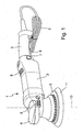
- Fig. 1 shows an example of a hand-held power tool 1 according to the present invention in the form of a random orbital polishing tool 1.
- the polisher 1 has a housing 2, essentially made of a plastic material.
- the polisher 1 is provided with a handle 3 at its rear end and a grip 4 at its front end.
- An electric power supply line 5 with an electric plug at its distal end exits the housing 2 at the rear end of the handle 3.
- a switch 6 is provided for activating and deactivating the power tool 1.
- the switch 6 can be continuously held in its activated position by means of a push button 7.
- the power tool 1 can be provided with a rotary adjustment means (not shown) for adjusting the rotational speed of the tool's motor.
- the housing 2 can be provided with cooling openings 8 for allowing heat from electronic components and/or the electric motor both located inside the housing 2 to dissipate into the environment.
- the power tool 1 shown in Fig. 1 has an electric motor.
- the machine tool according to the present invention could also be equipped with a pneumatic motor, which is especially advantageous in explosive environments, where sparks from an electric motor could provoke an explosion of an explosive mixture (e.g. oxygen and very fine dust) contained in the environment.
- an explosive mixture e.g. oxygen and very fine dust
- the machine tool 1 could alternatively be equipped with a rechargeable battery (not shown) located inside the housing 2. In that case the electric energy for driving the electric motor would be provided by the battery.
- the power tool 1 has a plate-like backing pad 9 rotatable about a rotational axis 10 and having a connection element (not shown) extending along the backing pad's rotational axis 10.
- the connection element is adapted for connecting the backing pad 9 to a backing pad holder (not shown) of the tool 1.
- a bottom surface 9a of the backing pad 9 is provided with means for attaching a polishing pad 11 according to the present invention.
- the attachment means can comprise a first layer of a hook-and-loop fastener (or Velcro®), wherein the top surface 11a of the polishing pad 11 is provided with the second layer of the hook-and-loop fastener.
- the two layers of the hook-and-loop fastener interact with one another in order to releasably but safely fix the polishing pad 11 to the bottom surface 9a of the backing pad 9.
- the plate-like backing pad 9 is made of a semi-rigid material, preferably a plastic material, which on the one hand is rigid enough to carry and support the polishing pad 11 during the intended use of the power tool 1 and to apply a force to the polishing pad 11 in a direction essentially downwards and parallel to the backing pad's rotational axis 10 and which on the other hand is flexible enough to avoid damage or scratching of the surface to be worked by the polishing pad 11.
- the polishing pad 11 is in particular used for polishing a workpiece in the form of a vehicle or car body or the hull or any other part of a boat or ship.
- the workpiece is preferably made of wood, metal, plastic or a composite material (e.g. glass fiber reinforced, GFR, or carbon fiber reinforced, CFR, material) provided with or without some kind of paint and/or varnish.
- Some kind of polishing paste may be applied to the working surface in order to enhance the polishing effect of the polishing pad.
- a multi-part polishing pad 11 comprising a bottom working surface 11b facing the workpiece to be polished during intended use of the power tool 1.
- the bottom working surface 11b comprises at least two pieces 12, 13 of polishing material with different characteristics (see Fig. 2 ).
- the different characteristics of the various pieces of the bottom working surface refer to one or more of a group comprising: the rigidity of the material of the two pieces, the type of material of the two pieces, and, in case of a polishing pad made of a foamed plastics material, the cell-structure of the foamed plastics material.
- the polishing pad 11 comprises a foamed plastics material made of Polyurethane with an open-cell structure.
- the characteristic by which the two pieces of the working surface 11b distinguish is the rigidity of the material used.
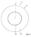
- Fig. 2 shows the plate-like backing pad 9 and the polishing pad 11 releasably attached thereto.
- the bottom working surface 11b of the polishing pad 11 comprises two pieces 12, 13 of polishing material with different rigidities.
- the entire polishing pad 11 comprises two separate pieces 12, 13.
- the bottom working surface 11b of the polishing pad 11 comprises one inner piece 12 and one outer circumferential piece 13 surrounding the inner piece 12, both located coaxially to the rotational axis 10 of the backing pad 9 and the polishing pad 11, respectively.
- the outer circumferential piece 13 preferably has a smaller rigidity than the inner piece 12.
- the bottom working surface 11b of the polishing pad 11 comprises two partial working surfaces, a circular partial working surface 12b and an annular partial working surface 13b. Both partial working surfaces 12b, 13b together form the polishing pad's working surface 11b.
- the material forming the central partial working surface 12b preferably the entire material of the polishing pad 11 extending from the partial working surface 12b to the opposite side 11a (see Fig. 3 ) of the polishing pad 11, has a larger rigidity than the material forming the outer annular partial working surface 13b, preferably of the entire material of the polishing pad 11 extending from the partial working surface 13b to the opposite side 11a of the polishing pad 11.
- the present invention is realized by providing material with different rigidities on the bottom working surface 11b of the polishing pad 11, for example in the form of inserts 12 which could be inserted in appropriate depressions or holes located on the bottom working surface 11b of the polishing pad 11.
- the polishing pad 11 is realized with at least two separate parts 12, 13 which can be individually handled and individually attached to and detached from the bottom surface 9a of the plate-like backing pad 9.
- the embodiments described hereinafter refer to a polishing pad 11 made up of a plurality of separate parts, for example parts 12, 13. This can be seen from Fig. 3 , where it is shown that the center piece 12 runs all the way through the polishing pad 11 to the top surface 11a, where it forms a separate circular partial top surface 12a. Similarly, the outer annular circumferential piece 13 runs all the way through the polishing pad 11 to the top surface 11a, where it forms a separate annular partial top surface 13a.
- Both partial top surfaces 12a, 13a together form the even and plane polishing pad's top surface 11a.
- Both partial surfaces 12a, 13a are provided with attachment means, e.g. part of a hook-and-loop fastener (Velcro®), wherein the other part of the hook-and-loop fastener is attached to the bottom surface 9a of the backing pad 9.
- attachment means e.g. part of a hook-and-loop fastener (Velcro®), wherein the other part of the hook-and-loop fastener is attached to the bottom surface 9a of the backing pad 9.
- the outer annular circumferential piece 13 having a certain characteristic extends beyond the partial bottom working surface 12b of the inner circular central piece 12 having another characteristic (e.g. a larger rigidity).
- the partial bottom working surface 13b extends by approximately 3-10 mm beyond the other partial bottom working surface 12b.
- the kind of intended use of the polishing pad 11 can be varied by applying a varying amount of downward pressure to the hand-held power tool 1 and by pressing the polishing pad 11 or rather its bottom working surface 11b onto the surface of the workpiece with more or less force.
- the power tool 1 and the polishing pad 11 are pressed onto the surface of the workpiece to be polished with a larger force.
- the outer annular circumferential piece 13 is compressed and the partial bottom working surface 12b of the inner circular central piece 12 comes into contact with the surface of the workpiece to be polished and can realize the more intense cutting polishing action. Then, when the deeper scratches and other defects in the workpiece's surface are eliminated to a large extent, the downward pressure applied to the power tool 1 and the polishing pad 11 can be reduced, thereby detaching the partial bottom working surface 12b of the inner circular central piece 12 from the surface of the workpiece to be polished. By doing so only the partial bottom working surface 13b of the outer annular circumferential piece 13 remains in contact with the surface of the workpiece to be polished and the soft finishing polishing action of the workpiece can be realized. So with a single multi-part polishing pad 11 according to the present invention two different types of uses (cutting and finishing action) of the power tool 1 can be realized.
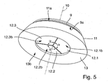
- Figs. 5 and 6 show a further embodiment of the polishing pad 11.
- the bottom working surface 11b or the polishing pad 11, respectively, of Figs. 5 and 6 comprises a single outer circumferential piece 13.
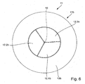
- the bottom working surface 11b or the polishing pad 11, respectively, of Figs. 5 and 6 comprises a plurality of inner central pieces 12.
- the polishing pad 11 comprises three inner central pieces 12.1, 12.2 and 12.3, each of which having the form of a partial circular area corresponding to a center angle of 120°.
- all three inner pieces 12.1, 12.2, 12.3 are made of the same material and have the same rigidity, being larger than the rigidity of the outer circumferential piece 13.
- the number of inner central pieces 12 and their form may vary from the shown embodiment.
- the three inner pieces 12.1, 12.2, 12.3 may be made of different materials and/or may have different rigidities.
- Each of the three inner pieces 12.1, 12.2, 12.3 has a bottom partial working surface 12.1b, 12.2b, 12.3b (see Fig. 5 ), together forming the partial working surface 12b of the inner central piece 12. Again, the partial working surfaces 12.1b, 12.2b, 12.3b and the partial working surface 13b of the outer circumferential piece 13 together form the working surface 11b of the polishing pad 11. The partial working surface 13 extends beyond the partial working surfaces 12.1b, 12.2b, 12.3b.
- each of the three inner pieces 12.1, 12.2, 12.3 has a partial top surface. Together these form the partial top surface 12a of the inner central piece 12. Together with the partial top surface 13a of the outer circumferential piece 13, the partial top surfaces of the three inner pieces 12.1, 12.2, 12.3 form the even and plane top surface 11a of the polishing pad 11.
- Each of the partial top surfaces of the three inner pieces 12.1, 12.2, 12.3 as well as the partial top surface of the outer circumferential piece 13 are provided with attachment means, e.g. part of a hook-and-loop fastener (Velcro®), wherein the other part of the hook-and-loop fastener is attached to the bottom surface 9a of the backing pad 9.
- attachment means e.g. part of a hook-and-loop fastener (Velcro®), wherein the other part of the hook-and-loop fastener is attached to the bottom surface 9a of the backing pad 9.
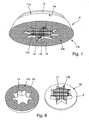
- Figs. 7-9 show yet another embodiment of the present invention. Seen in the main plane of extension of the bottom working surface 11b of the polishing pad 11, the inner central piece 12 has a cross-sectional form of a star. Of course, any other form (e.g. triangle, rectangle or any other multi-angle form) can be chosen, too.
- the outer circumferential piece 13 has an opening 14 corresponding to the star-form of the inner central piece 12 and adapted for receiving the same.
- Fig. 8 shows the two pieces 12, 13 constituting the polishing pad 11 separate from one another, wherein the inner central piece 12 is attached to the bottom surface 9a of the backing pad 9 and the outer circumferential piece 13 is detached from the backing pad 9.
- the star-shaped opening 14 for receiving the inner central piece 12 is clearly visible.
- the top surface 11a of the polishing pad 11 is shown, where the attachment means comprising loops or hooks as part of the hook-and-loop fastener for attaching the polishing pad 11 to the corresponding part of the hook-and-loop fastener on the bottom surface 9a of the backing pad 9 are provided on both the partial top surfaces 12a, 13a of the polishing pad 11.
- the at least one outer circumferential piece 13 of the polishing pad 11 has at least one opening 14 extending from the bottom working surface 11b of the polishing pad 11 to the top attachment surface 11a of the polishing pad 11 and having an inner circumferential form (in the embodiment of Figs. 7-9 a star-shape) corresponding to an outer circumferential form of the at least one inner part 12 of the polishing pad 11, to be received in said at least one opening 14.
- the inner circumferential form of the at least one opening 14 may have the form of a circle, an ellipse, a triangle, a rectangle, a star or any other kind of multi-angle form, and the at least one inner piece 12 of the polishing pad 11 to be received in said at least one opening 14 has a corresponding outer circumferential form.
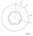
- Figs. 10 and 11 show yet another embodiment of the polishing pad 11 according to the present invention, similar to the embodiment of Figs. 7-9 .
- the acute angels of the star-shape have been rounded.
- This circumferential form of the inner central piece 12 and of the opening 14 in the outer circumferential piece 13 may have advantages in the sense that the rounded angles are not worn as fast as they will probably be in the embodiment of Figs. 7-9 during the intended use of the polishing pad 11.
- polishing paste or the like will be gathered in the angles of the polishing pad 11 during its intended use, if the angles are rounded.
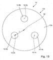
- Fig. 12 shows yet another embodiment of the polishing pad 11 according to the present invention in a perspective view and Fig. 13 shows the same embodiment in a bottom view.
- the outer circumferential piece 13 has a plurality of circular openings 14 located in a distance r (see Fig. 13 ) to the rotational axis 10 of the backing pad 9 and the polishing pad 11, respectively.
- Inner circular pieces 12.1, 12.2, 12.3 are inserted in each of the openings 14.
- each of the inner circular pieces 12 comprises a partial top surface 12a (not shown in Figs.
- the inner pieces 12.1, 12.2, 12.3 are made of the same material and have the same rigidity.
- the inner pieces 12.1, 12.2, 12.3 are made of different materials and/or have different rigidities.
- the distances r from the centers 12.1c, 12.2c, 12.3c of the inner pieces 12 to the rotational axis 10 of the backing pad 9 and the polishing pad 11, respectively, is the same for each of the inner pieces 12.1, 12.2, 12.3.
- the distances r could also be different for each of the inner pieces 12.1, 12.2, 12.3.
- the number, form and size of the plurality of inner pieces 12.1, 12.2, 12.3 could vary from what is shown in Figs. 12 and 13 .
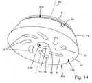
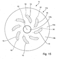
- Figs. 14 and 15 show yet another embodiment of a polishing pad 11 according to the present invention.
- the bottom working surface 11b of the polishing pad 11 comprises a three-dimensional structure.
- the structure comprises slots 15 with a longitudinal extension along a curved line 16 (see Fig. 15 ).
- the slots 15 are located circumferentially around the rotational axis 10 of the plate-like backing pad 9 or the polishing pad 11, respectively.
- the lines 16 extend in a roughly radial direction. All lines 16 are curved in the same direction.
- the curved lines 16 of the slots 15 may intersect in the rotational axis 10.
- the slots 15 extend through the entire polishing pad 11 from its top attachment surface 11a to its bottom working surface 11b.
- the slots 15 are provided in the outer circumferential part 13 of the polishing pad 11 forming recesses in the bottom working surface 13b.
- the outer circumferential part 13 has a central circular opening 14 for receiving the inner central piece 12 therein.
- the inner central piece 12 has a circular cross section and is located concentrically to the rotational axis 10.
- the number, form and size of the slots can vary from what is shown in Figs. 14 and 15 .
- the three dimensional structure of the bottom working surface may also be realized in any other way.
- the three-dimensional structure is not exclusively embodied on the partial working surface 13b of the outer circumferential piece 13, but at least in part could also be embodied on the partial working surface 12b of the inner central part 12.
- the three-dimensional structure could also be realized, for example, by means of a waffle structure having depressions and hills displaced in respect to one another and located on at least part of the bottom working surface 11b of the polishing pad 11 (not shown).
- Figs. 16 and 17 show yet another embodiment similar to the one shown in Figs. 14 and 15 .
- the outer circumferential part 13 of the polishing pad 11 does not have a central opening 14 for receiving an inner central piece 12.
- the slots 15 provided in the polishing pad 11 form openings in which inner pieces 12 are located, each having the curved form of the slots 15.
- the partial working surfaces 12b of all inner pieces 12 inserted into the slots 15 form part of the working surface 11b of the polishing pad 11.
- the partial working surface 13b of the outer circumferential piece 13 extends beyond the partial working surfaces 12b of all inner pieces 12.
- the rigidity of the material of the outer circumferential piece 13 is smaller than the rigidity of the inserted inner pieces 12.
Abstract
Description
- The present invention refers to a polishing pad, adapted for being detachably attached to a bottom surface of a plate-like backing pad of a hand-held power tool. The backing pad is actuated by an electric or pneumatic motor of the hand-held power tool, in order to perform a purely rotating, random orbital or roto-orbital working movement. Hence, the power tool can be a purely rotational, a random orbital or a roto orbital (dual action, gear driven) polisher. The polishing pad comprises a bottom working surface facing a workpiece to be polished during intended use of the power tool.
- Polishing pads of the above mentioned kind are well known in the prior art in a plurality of different embodiments. They usually are used for polishing a workpiece in the form of a vehicle or car body or the hull or any other part of a boat or ship. The workpiece is preferably made of wood, metal, plastic or a composite material (e.g. glass fiber reinforced, GFR, or carbon fiber reinforced, CFR, material) and may be provided with or without some kind of base coat, primer, paint and/or varnish. Some kind of polishing paste or polishing liquid may be applied to the working surface in order to enhance the polishing effect of the
polishing pad 11 during its intended use. Such polishing pads are manufactured and sold by a large number of companies, for example RUPES S.p.A., 3M, Lake Country and others. - For example, a polishing pad can be made of a sponge-like material, in particular a plastics material like polyurethane with an open-cell structure. In this case the bottom working surface of the polishing pad is realized by the sponge-like material of the pad. Furthermore, another type of polishing pad can comprise a support structure consisting of a plate-like element made of a plastics material, like polyurethane with a closed-cell structure, with microfibers attached to the bottom surface of the support structure. The microfibers are made of polyester and/or polyamide. In this case the bottom working surface of the polishing pad is realized by the microfibers. Finally, another type of polishing pad can comprise a support structure consisting of a sponge-like element made of a plastics material, like polyurethane with an open-cell structure, with natural or synthetic wool attached to the bottom surface of the support structure.
- Known polishing pads or their bottom working surfaces, respectively, can have a variety of different characteristics, e.g. they can be made of different materials (e.g. foamed plastics material (e.g. polyurethane), natural or synthetic wool, microfibers), they can have different rigidities or - in the case of foamed plastics material - have different cell structures (e.g. open-cell or closed-cell structure) and different cell sizes.
- Conventional polishing pads are available in different rigidities for different intended uses of the pad. For example, foam pads having a larger rigidity are adapted for effecting a more intense cutting polishing action of a workpiece to be polished, in order to remove a larger amount of material from a surface of a workpiece to be polished and to delete deeper scratches and other defects in the workpiece's surface. In contrast thereto, foam pads having a smaller rigidity are adapted for effecting a soft finishing polishing action of the workpiece to be polished, in order to delete any swirls or other fine marks which may result from the previous cutting polishing action and to obtain a very even, smooth and glossy polished surface. The different rigidities of the foamed material are a result of:
- different materials used (e.g. Polyamide (PA), Polyester, etc.),
- different cell structures (closed-cell or open-cell structure) and/or
- different cell sizes.
- The different rigidities of microfiber or wool polishing pads are a result of:
- different lengths of the microfiber or wool fibers,
- different diameters of the fibers and/or
- different desities of the fibers (number of fibers per cm2).
- In order to switch between the different intended uses of the polishing pads, they have to be exchanged during the process of working the surface of the workpiece to be polished. This is cumbersome and time consuming. Therefore, it would be desirous to provide for a single polishing pad which can be used for different intended uses, in particular for performing different polishing actions (e.g. cutting or finishing action) with a single polishing pad.
- In order to solve this problem the present invention suggests a polishing pad of the above mentioned kind wherein the bottom working surface has at least two pieces of polishing material with different characteristics, and wherein a bottom working surface of at least one of the pieces of the polishing pad having a first characteristic extends beyond a bottom working surface of at least another of the pieces of the polishing pad having a second characteristic.
- The different characteristics of the various pieces of the bottom working surface refer to one or more of a group comprising: the rigidity of the material of the two pieces, the type of material of the two pieces, and, in case of a polishing pad made of a foamed plastics material, the structure and/or the size of the cells of the foamed plastics material.
- In order to determine the rigidity or compliance of a foamed material having a cell structure, a precisely cut sample of the material may be compressed to 25%, 40% and 65% of its original height and the force necessary for the various degrees of compression is determined. The larger the rigidity of the material is, the larger the force necessary for obtaining a given compression of the material will be. Hence, the force is a measure of the rigidity of the material. The larger the compliance of the material is, the smaller the necessary force is in order to compress the material by a given amount. Depending on the intended use of the foamed material, there are a large variety of different foam materials available having different rigidities or compliances.
- The present invention proposes a polishing pad having a bottom working surface facing the workpiece to be polished during intended use of the power tool, which consists of at least two pieces having different characteristics. Due to their different characteristics these pieces of the bottom working surface of the polishing pad are adapted to realize different uses of the polishing pad (e.g. cutting or finishing action). For example, at least one of the pieces having a first characteristic may be used for effecting a more intense cutting polishing action of a workpiece, in order to remove a larger amount of material from a surface of the workpiece and to delete deeper scratches and other defects in the workpiece's surface. In contrast thereto, at least one of the pieces having a second characteristic may be used for effecting a soft finishing polishing action of the workpiece to be polished, in order to delete any swirls or other fine marks, which may result from the previous cutting polishing action and to obtain a very even and smooth polished surface of the workpiece. So the present invention proposes a single polishing pad which can be used for different intended uses.
- According to the present invention it is suggested that a bottom working surface of at least one of the pieces of the bottom working surface of the polishing pad having a first characteristic extends beyond a bottom working surface of at least another of the pieces of the bottom working surface of the polishing pad having a second characteristic. The first and second characteristics are different. This means that the pieces having the first and second characteristics are made of different types of material (e.g. natural or synthetic wool, microfibers, Polyamide, Polyester or Polyurethane) or a combination of some of these materials, are made of material having different rigidities or - in the case they are made of the same type of foamed plastics material, the foamed plastics material of the two pieces has different cell-structures and/or cell-sizes. Preferably, the bottom working surface of said at least one piece of the bottom working surface of the polishing pad having a first characteristic extends 3-10 mm beyond the bottom working surface of said at least one piece of the bottom working surface of the polishing pad having a second characteristic.
- In the case where the different characteristics of the two pieces of the bottom working surface of the polishing pad comprise materials having different rigidities, it is suggested that a bottom working surface of at least one of the pieces of the bottom working surface of the polishing pad having a smaller rigidity extends beyond a bottom working surface of at least another of the pieces of the bottom working surface of the polishing pad having a larger rigidity. Preferably, the bottom working surface of said at least one piece of the bottom working surface of the polishing pad having a smaller rigidity extends 3-10 mm beyond the bottom working surface of said at least one piece of the bottom working surface of the polishing pad having a larger rigidity.
- This embodiment has the advantage that the kind of intended use of the polishing pad (e.g. cutting action or finishing action) can be varied simply by applying a varying amount of pressure to the hand held power tool and by pressing the polishing pad onto the surface of the workpiece with more or less force. For example, in order to realize a more intense cutting polishing action at the beginning of the process of working the surface of the workpiece, the power tool and the polishing pad are pressed onto the surface of the workpiece to be polished with a larger force. By doing so the at least one of the pieces having a smaller rigidity is compressed and the bottom working surface of the at least one of the pieces having a larger rigidity comes into contact with the surface of the workpiece to be polished and can realize the more intense cutting polishing action. Then, when all the deeper scratches and other defects in the workpiece's surface are deleted, the pressure applied to the power tool and the polishing pad can be reduced thereby detaching the bottom working surface of the at least one of the pieces having a larger rigidity from the surface of the workpiece to be polished. By doing so only the bottom working surface of the at least one of the pieces having a smaller rigidity remains in contact with the surface of the workpiece to be polished and the soft finishing polishing action of the workpiece to be polished can be realized.
- The polishing pad according to the present invention comprises at least two pieces having different characteristics. These pieces may be distributed in the polishing pad in a variety of different designs according to the individual needs of the customers; to the different applications of the polishing pad and to the different workpiece surfaces to be polished. The various pieces of the polishing pad can have almost any possible cross section form, and may have different colors and designs. Preferably, the bottom working surface of the polishing pad comprises at least one inner piece having the second characteristic and at least one outer circumferential piece surrounding the at least one inner piece and having the first characteristic. The at least one inner piece of the polishing pad may be located in the center of the polishing pad or in any desired decentral position in respect to a rotational axis of the plate-like backing pad and of the polishing pad, respectively. If the at least one inner piece is located in the center of the polishing pad, the polishing pad will usually comprise only one inner piece. If the at least one inner piece is located in a decentral position, the polishing pad will usually comprise a plurality of inner pieces.
- The polishing pad is adapted to be detachably attached to the bottom surface of the plate-like backing pad by any type of attachment means or attachment layer. According to a further preferred embodiment of the present invention, it is suggested that the polishing pad is adapted to be detachably attached to the bottom surface of the plate-like backing pad by means of hook-and-loop attachment means (e.g. Velcro®) provided in part on the bottom surface of the backing pad and in part on a top surface of the polishing pad, facing the bottom surface of the backing pad. Hook-and-loop attachment means allow a long-term, secure and easy to achieve and easy to release connection of the polishing pad to the backing pad.
- Preferably, the at least two pieces of polishing material with different characteristics are embodied as separate parts, which are each detachably attached to the bottom surface of the plate-like backing pad independently from one another. This has the advantage that each of the pieces can be replaced separately depending on the individual wear of the piece. The top surface of each of the separate parts has attachment means for detachably attaching the part to the bottom surface of the backing pad. In order to attach the multi-part polishing pad to the backing pad, preferably first at least one outer circumferential part is attached to the bottom surface of the backing pad. The at least one circumferential part comprises openings, into which the inner parts can then be introduced and attached to the bottom surface of the backing pad in the correct position.
- In particular, it is suggested that the at least one circumferential part of the polishing pad has at least one opening extending from the bottom working surface of the polishing pad to the top surface of the polishing pad and having an inner circumferential form corresponding to an outer circumferential form of the at least one inner part of the polishing pad, to be received in said at least one opening. Hence, when all parts or pieces, respectively, of the polishing pad are attached to the bottom surface of the plate-like backing pad it is as if a single polishing pad consisting of different materials having different characteristics was attached to the backing pad, wherein the bottom working surfaces of the parts or pieces, respectively, are on different levels and do not form a single even plane.
- As mentioned above, the possible design of the multi-part polishing pad is almost unlimited. According to a preferred embodiment the inner circumferential form of the at least one opening in the at least one circumferential part of the polishing pad has the form of a circle, an ellipse, a triangle, a rectangle, a star or any other kind of multi-angled or polygon form, and the at least one inner piece of the polishing pad to be received in said at least one opening has a corresponding outer circumferential form. It may be advantageous if sharp or acute angles of the outer circumferential form of the inner parts are rounded.
- Instead of the polishing pad being made up of a plurality of separate parts to be individually attached to the bottom surface of the plate-like backing pad, it is also possible that the at least two pieces of polishing material with different characteristics are laminated together before detachably attaching them to the bottom surface of the backing pad in order to form a single part to be detachably attached to the bottom surface of the backing pad. This has the advantage that the positioning, attaching and removing of the multi-part polishing pad is particularly easy and fast.
- Preferably, it is suggested that the at least two pieces of polishing material with different characteristics are located concentrically in respect to a rotational axis of the plate-like backing pad. For example, the inner part may have a circular form and the outer circumferential part may have an annular form with a central opening for receiving the inner part. This is probably one of the easiest ways of designing the polishing pad according to the present invention.
- It is possible to use any desired and known material for the at least two pieces of the polishing pad. According to yet another preferred embodiment of the present invention it is suggested that at least the bottom working surfaces of the at least two pieces constituting the polishing pad, preferably not only the bottom working surface but rather the entire pieces, comprise a foamed plastics material having an open-cell or a closed-cell structure, wool or microfiber. The foamed plastics material can comprise, for example, Polyamide, Polyester, and Polyurethane. According to a preferred embodiment, the entire two pieces are made of foamed plastics material with an open-cell structure and different rigidities.
- It may further be advantageous if at least one of the bottom working surfaces of the at least two pieces constituting the polishing pad comprise a three-dimensional structure, overlying the cell structure of foamed plastics material on the bottom working surface of the polishing pad. This structure may comprise, for example, one or more slots or channels having a straight or a sickle shaped arched form, or a waffle structure having depressions and hills displaced in respect to one another, wherein the distance of the highest points of the hills to the lowest points of the depressions in a direction perpendicular to the main extension plane of the bottom working surface is approximately in the range of 2mm to 10mm. The distance of the highest point of a first hill to the highest point of a neighboring hill in the main extension plane of the bottom working surface is approximately in the range of 5mm to 20mm. Slots, channels or depressions may serve for first receiving and then slowly releasing an abrasive paste or the like during the polishing procedure. Furthermore, by means of the three-dimensional structure the efficiency of the polishing process can be enhanced. Finally, the structure can give the polishing pad a special, unique design, in order to distinguish it optically from other known polishing pads.
- It is also suggested that at least one of the bottom working surfaces of the at least two pieces constituting the polishing pad comprise small abrasive particles, in particular in the form of crystals, incorporated in the at least one bottom working surface. These abrasive particles are slowly released from the bottom surface over a longer period of time (e.g. half an hour) during the polishing process and serve for enhancing the efficiency of the polishing process. The fact that the abrasive particles are incorporated in the bottom working surface has the advantage that no separate abrasive paste or the like has to be applied to the bottom working surface of the polishing pad and/or the workpiece's surface before starting and during the polishing process. During the polishing process the size of the particles may decrease. So at the beginning of the polishing process when the size of the particles is relatively large, a more intense cutting polishing action of the workpiece can be realized. As time goes by and the size of the particles decreases, a soft finishing polishing action of the workpiece to be polished can be realized.
- Finally, it is suggested that the at least one piece of the polishing pad having a smaller rigidity is adapted for effecting a soft finishing polishing action of the workpiece to be polished. And the at least one piece of the polishing pad having a larger rigidity is preferably adapted for effecting a more intense cutting polishing action of the workpiece to be polished.
- Further characteristics and advantages of the present invention will be described hereinafter in more detail making reference to the accompanying figures. The figures show:
- Fig. 1
- a hand-held power tool comprising a polishing pad according to the present invention;
- Fig. 2
- a perspective view on a bottom working surface of a polishing pad according to a first embodiment of the present invention, attached to a plate-like backing pad;
- Fig. 3
- a perspective view on a top surface of the polishing pad of
Fig. 2 ; - Fig. 4
- a plan view on the bottom working surface of the polishing pad of
Fig. 2 ; - Fig. 5
- a perspective view on a bottom working surface of a polishing pad according to another embodiment of the present invention, attached to a plate-like backing pad;
- Fig. 6
- a plan view on the bottom working surface of the polishing pad of
Fig. 5 ; - Fig. 7
- a perspective view on a bottom working surface of a polishing pad according to another embodiment of the present invention, attached to a plate-like backing pad;
- Fig. 8
- a perspective view on the bottom working surface of the polishing pad of
Fig. 7 , separated into an outer circumferential piece and in inner central piece; - Fig. 9
- a perspective view on the top surface of the polishing pad of
Fig. 7 ; - Fig. 10
- a perspective view on a bottom working surface of a polishing pad according to another embodiment of the present invention, attached to a plate-like backing pad;
- Fig. 11
- a plan view on the bottom working surface of the polishing pad of
Fig. 10 ; - Fig. 12
- a perspective view on a bottom working surface of a polishing pad according to another embodiment of the present invention, attached to a plate-like backing pad;
- Fig. 13
- a plan view on the bottom working surface of the polishing pad of
Fig. 12 ; - Fig. 14
- a perspective view on a bottom working surface of a polishing pad according to another embodiment of the present invention, attached to a plate-like backing pad;
- Fig. 15
- a plan view on the bottom working surface of the polishing pad of
Fig. 14 ; - Fig. 16
- a perspective view on a bottom working surface of a polishing pad according to another embodiment of the present invention, attached to a plate-like backing pad; and
- Fig. 17
- a plan view on the bottom working surface of the polishing pad of
Fig. 16 . -
Fig. 1 shows an example of a hand-held power tool 1 according to the present invention in the form of a random orbital polishing tool 1. The polisher 1 has ahousing 2, essentially made of a plastic material. The polisher 1 is provided with ahandle 3 at its rear end and agrip 4 at its front end. An electricpower supply line 5 with an electric plug at its distal end exits thehousing 2 at the rear end of thehandle 3. At the bottom side of the handle 3 aswitch 6 is provided for activating and deactivating the power tool 1. Theswitch 6 can be continuously held in its activated position by means of apush button 7. The power tool 1 can be provided with a rotary adjustment means (not shown) for adjusting the rotational speed of the tool's motor. Thehousing 2 can be provided withcooling openings 8 for allowing heat from electronic components and/or the electric motor both located inside thehousing 2 to dissipate into the environment. - The power tool 1 shown in
Fig. 1 has an electric motor. Of course, the machine tool according to the present invention could also be equipped with a pneumatic motor, which is especially advantageous in explosive environments, where sparks from an electric motor could provoke an explosion of an explosive mixture (e.g. oxygen and very fine dust) contained in the environment. Furthermore, instead of the connection of the machine tool 1 to a mains power supply by means of theelectric cable 5, the machine tool 1 could alternatively be equipped with a rechargeable battery (not shown) located inside thehousing 2. In that case the electric energy for driving the electric motor would be provided by the battery. - The power tool 1 has a plate-
like backing pad 9 rotatable about arotational axis 10 and having a connection element (not shown) extending along the backing pad'srotational axis 10. The connection element is adapted for connecting thebacking pad 9 to a backing pad holder (not shown) of the tool 1. Abottom surface 9a of thebacking pad 9 is provided with means for attaching apolishing pad 11 according to the present invention. The attachment means can comprise a first layer of a hook-and-loop fastener (or Velcro®), wherein thetop surface 11a of thepolishing pad 11 is provided with the second layer of the hook-and-loop fastener. The two layers of the hook-and-loop fastener interact with one another in order to releasably but safely fix thepolishing pad 11 to thebottom surface 9a of thebacking pad 9. - The plate-
like backing pad 9 is made of a semi-rigid material, preferably a plastic material, which on the one hand is rigid enough to carry and support thepolishing pad 11 during the intended use of the power tool 1 and to apply a force to thepolishing pad 11 in a direction essentially downwards and parallel to the backing pad'srotational axis 10 and which on the other hand is flexible enough to avoid damage or scratching of the surface to be worked by thepolishing pad 11. Thepolishing pad 11 is in particular used for polishing a workpiece in the form of a vehicle or car body or the hull or any other part of a boat or ship. The workpiece is preferably made of wood, metal, plastic or a composite material (e.g. glass fiber reinforced, GFR, or carbon fiber reinforced, CFR, material) provided with or without some kind of paint and/or varnish. Some kind of polishing paste may be applied to the working surface in order to enhance the polishing effect of the polishing pad. - According to the present invention a
multi-part polishing pad 11 is proposed, comprising abottom working surface 11b facing the workpiece to be polished during intended use of the power tool 1. Thebottom working surface 11b comprises at least twopieces Fig. 2 ). The different characteristics of the various pieces of the bottom working surface refer to one or more of a group comprising: the rigidity of the material of the two pieces, the type of material of the two pieces, and, in case of a polishing pad made of a foamed plastics material, the cell-structure of the foamed plastics material. In the following, purely by example, thepolishing pad 11 comprises a foamed plastics material made of Polyurethane with an open-cell structure. Further, purely by example the characteristic by which the two pieces of the workingsurface 11b distinguish is the rigidity of the material used. -
Fig. 2 shows the plate-like backing pad 9 and thepolishing pad 11 releasably attached thereto. Thebottom working surface 11b of thepolishing pad 11 comprises twopieces Fig. 2 theentire polishing pad 11 comprises twoseparate pieces Fig. 2 thebottom working surface 11b of thepolishing pad 11 comprises oneinner piece 12 and one outercircumferential piece 13 surrounding theinner piece 12, both located coaxially to therotational axis 10 of thebacking pad 9 and thepolishing pad 11, respectively. The outercircumferential piece 13 preferably has a smaller rigidity than theinner piece 12. Thebottom working surface 11b of thepolishing pad 11 according to the invention comprises two partial working surfaces, a circular partial workingsurface 12b and an annular partial workingsurface 13b. Both partial workingsurfaces surface 11b. The material forming the central partial workingsurface 12b, preferably the entire material of thepolishing pad 11 extending from the partial workingsurface 12b to theopposite side 11a (seeFig. 3 ) of thepolishing pad 11, has a larger rigidity than the material forming the outer annular partial workingsurface 13b, preferably of the entire material of thepolishing pad 11 extending from the partial workingsurface 13b to theopposite side 11a of thepolishing pad 11. With other words the present invention is realized by providing material with different rigidities on thebottom working surface 11b of thepolishing pad 11, for example in the form ofinserts 12 which could be inserted in appropriate depressions or holes located on thebottom working surface 11b of thepolishing pad 11. - Preferably, the
polishing pad 11 is realized with at least twoseparate parts bottom surface 9a of the plate-like backing pad 9. The embodiments described hereinafter refer to apolishing pad 11 made up of a plurality of separate parts, forexample parts Fig. 3 , where it is shown that thecenter piece 12 runs all the way through thepolishing pad 11 to thetop surface 11a, where it forms a separate circular partialtop surface 12a. Similarly, the outer annularcircumferential piece 13 runs all the way through thepolishing pad 11 to thetop surface 11a, where it forms a separate annular partialtop surface 13a. Both partialtop surfaces top surface 11a. Bothpartial surfaces bottom surface 9a of thebacking pad 9.
In the embodiment ofFigs. 2 to 4 the outer annularcircumferential piece 13 having a certain characteristic (e.g. a smaller rigidity) extends beyond the partialbottom working surface 12b of the inner circularcentral piece 12 having another characteristic (e.g. a larger rigidity). Preferably the partialbottom working surface 13b extends by approximately 3-10 mm beyond the other partialbottom working surface 12b. - With the partial
bottom working surfaces polishing pad 11 or rather itsbottom working surface 11b onto the surface of the workpiece with more or less force. For example, in order to realize a more intense cutting polishing action at the beginning of a process of working the surface of the workpiece, the power tool 1 and thepolishing pad 11 are pressed onto the surface of the workpiece to be polished with a larger force. By doing so the the outer annularcircumferential piece 13 is compressed and the partialbottom working surface 12b of the inner circularcentral piece 12 comes into contact with the surface of the workpiece to be polished and can realize the more intense cutting polishing action. Then, when the deeper scratches and other defects in the workpiece's surface are eliminated to a large extent, the downward pressure applied to the power tool 1 and thepolishing pad 11 can be reduced, thereby detaching the partialbottom working surface 12b of the inner circularcentral piece 12 from the surface of the workpiece to be polished. By doing so only the partialbottom working surface 13b of the outer annularcircumferential piece 13 remains in contact with the surface of the workpiece to be polished and the soft finishing polishing action of the workpiece can be realized. So with a singlemulti-part polishing pad 11 according to the present invention two different types of uses (cutting and finishing action) of the power tool 1 can be realized. -
Figs. 5 and6 show a further embodiment of thepolishing pad 11. Just like thepolishing pad 11 of the first embodiment ofFigs. 2-4 , thebottom working surface 11b or thepolishing pad 11, respectively, ofFigs. 5 and6 comprises a single outercircumferential piece 13. However, instead of only one inner circularcentral piece 12, thebottom working surface 11b or thepolishing pad 11, respectively, ofFigs. 5 and6 comprises a plurality of innercentral pieces 12. In this embodiment, thepolishing pad 11 comprises three inner central pieces 12.1, 12.2 and 12.3, each of which having the form of a partial circular area corresponding to a center angle of 120°. In the embodiment, all three inner pieces 12.1, 12.2, 12.3 are made of the same material and have the same rigidity, being larger than the rigidity of the outercircumferential piece 13. Of course, the number of innercentral pieces 12 and their form may vary from the shown embodiment. Furthermore, the three inner pieces 12.1, 12.2, 12.3 may be made of different materials and/or may have different rigidities. - Each of the three inner pieces 12.1, 12.2, 12.3 has a bottom partial working surface 12.1b, 12.2b, 12.3b (see
Fig. 5 ), together forming the partial workingsurface 12b of the innercentral piece 12. Again, the partial working surfaces 12.1b, 12.2b, 12.3b and the partial workingsurface 13b of the outercircumferential piece 13 together form the workingsurface 11b of thepolishing pad 11. The partial workingsurface 13 extends beyond the partial working surfaces 12.1b, 12.2b, 12.3b. - Similar to what is shown in
Fig. 3 regarding the first embodiment, each of the three inner pieces 12.1, 12.2, 12.3 has a partial top surface. Together these form the partialtop surface 12a of the innercentral piece 12. Together with the partialtop surface 13a of the outercircumferential piece 13, the partial top surfaces of the three inner pieces 12.1, 12.2, 12.3 form the even and planetop surface 11a of thepolishing pad 11. Each of the partial top surfaces of the three inner pieces 12.1, 12.2, 12.3 as well as the partial top surface of the outercircumferential piece 13 are provided with attachment means, e.g. part of a hook-and-loop fastener (Velcro®), wherein the other part of the hook-and-loop fastener is attached to thebottom surface 9a of thebacking pad 9. -
Figs. 7-9 show yet another embodiment of the present invention. Seen in the main plane of extension of thebottom working surface 11b of thepolishing pad 11, the innercentral piece 12 has a cross-sectional form of a star. Of course, any other form (e.g. triangle, rectangle or any other multi-angle form) can be chosen, too. The outercircumferential piece 13 has anopening 14 corresponding to the star-form of the innercentral piece 12 and adapted for receiving the same.Fig. 8 shows the twopieces polishing pad 11 separate from one another, wherein the innercentral piece 12 is attached to thebottom surface 9a of thebacking pad 9 and the outercircumferential piece 13 is detached from thebacking pad 9. The star-shapedopening 14 for receiving the innercentral piece 12 is clearly visible. InFig. 9 thetop surface 11a of thepolishing pad 11 is shown, where the attachment means comprising loops or hooks as part of the hook-and-loop fastener for attaching thepolishing pad 11 to the corresponding part of the hook-and-loop fastener on thebottom surface 9a of thebacking pad 9 are provided on both the partialtop surfaces polishing pad 11. - Generally speaking, the at least one outer
circumferential piece 13 of thepolishing pad 11 has at least oneopening 14 extending from thebottom working surface 11b of thepolishing pad 11 to thetop attachment surface 11a of thepolishing pad 11 and having an inner circumferential form (in the embodiment ofFigs. 7-9 a star-shape) corresponding to an outer circumferential form of the at least oneinner part 12 of thepolishing pad 11, to be received in said at least oneopening 14. In particular, the inner circumferential form of the at least oneopening 14 may have the form of a circle, an ellipse, a triangle, a rectangle, a star or any other kind of multi-angle form, and the at least oneinner piece 12 of thepolishing pad 11 to be received in said at least oneopening 14 has a corresponding outer circumferential form. -
Figs. 10 and11 show yet another embodiment of thepolishing pad 11 according to the present invention, similar to the embodiment ofFigs. 7-9 . In contrast thereto, the acute angels of the star-shape have been rounded. This circumferential form of the innercentral piece 12 and of theopening 14 in the outercircumferential piece 13 may have advantages in the sense that the rounded angles are not worn as fast as they will probably be in the embodiment ofFigs. 7-9 during the intended use of thepolishing pad 11. Furthermore, by far less polishing paste or the like will be gathered in the angles of thepolishing pad 11 during its intended use, if the angles are rounded. -
Fig. 12 shows yet another embodiment of thepolishing pad 11 according to the present invention in a perspective view andFig. 13 shows the same embodiment in a bottom view. The outercircumferential piece 13 has a plurality ofcircular openings 14 located in a distance r (seeFig. 13 ) to therotational axis 10 of thebacking pad 9 and thepolishing pad 11, respectively. Inner circular pieces 12.1, 12.2, 12.3 are inserted in each of theopenings 14. Preferably, each of the innercircular pieces 12 comprises a partialtop surface 12a (not shown inFigs. 12 and13 ) comprising loops or hooks as part of the hook-and-loop fastener for attaching thepolishing pad 11 to the corresponding part of the hook-and-loop fastener on thebottom surface 9a of thebacking pad 9. Preferably, the inner pieces 12.1, 12.2, 12.3 are made of the same material and have the same rigidity. Of course, it would also be possible that the inner pieces 12.1, 12.2, 12.3 are made of different materials and/or have different rigidities. In the embodiment ofFigs. 12 and13 the distances r from the centers 12.1c, 12.2c, 12.3c of theinner pieces 12 to therotational axis 10 of thebacking pad 9 and thepolishing pad 11, respectively, is the same for each of the inner pieces 12.1, 12.2, 12.3. Of course the distances r could also be different for each of the inner pieces 12.1, 12.2, 12.3. Furthermore, the number, form and size of the plurality of inner pieces 12.1, 12.2, 12.3 could vary from what is shown inFigs. 12 and13 . -
Figs. 14 and15 show yet another embodiment of apolishing pad 11 according to the present invention. In this embodiment, thebottom working surface 11b of thepolishing pad 11 comprises a three-dimensional structure. The structure comprisesslots 15 with a longitudinal extension along a curved line 16 (seeFig. 15 ). Theslots 15 are located circumferentially around therotational axis 10 of the plate-like backing pad 9 or thepolishing pad 11, respectively. Thelines 16 extend in a roughly radial direction. Alllines 16 are curved in the same direction. Thecurved lines 16 of theslots 15 may intersect in therotational axis 10. Theslots 15 extend through theentire polishing pad 11 from itstop attachment surface 11a to itsbottom working surface 11b. In the embodiment shown, theslots 15 are provided in the outercircumferential part 13 of thepolishing pad 11 forming recesses in thebottom working surface 13b. The outercircumferential part 13 has a centralcircular opening 14 for receiving the innercentral piece 12 therein. The innercentral piece 12 has a circular cross section and is located concentrically to therotational axis 10. - Of course, the number, form and size of the slots can vary from what is shown in
Figs. 14 and15 . Furthermore, instead of the slots, the three dimensional structure of the bottom working surface may also be realized in any other way. Further, it would also be possible, that the three-dimensional structure is not exclusively embodied on the partial workingsurface 13b of the outercircumferential piece 13, but at least in part could also be embodied on the partial workingsurface 12b of the innercentral part 12. The three-dimensional structure could also be realized, for example, by means of a waffle structure having depressions and hills displaced in respect to one another and located on at least part of thebottom working surface 11b of the polishing pad 11 (not shown). - Finally,
Figs. 16 and17 show yet another embodiment similar to the one shown inFigs. 14 and15 . In contrast to that embodiment, the outercircumferential part 13 of thepolishing pad 11 does not have acentral opening 14 for receiving an innercentral piece 12. Rather, in this embodiment, theslots 15 provided in thepolishing pad 11 form openings in whichinner pieces 12 are located, each having the curved form of theslots 15. The partial working surfaces 12b of allinner pieces 12 inserted into theslots 15 form part of the workingsurface 11b of thepolishing pad 11. Thepartial working surface 13b of the outercircumferential piece 13 extends beyond the partial workingsurfaces 12b of allinner pieces 12. Again, it is preferred that the rigidity of the material of the outercircumferential piece 13 is smaller than the rigidity of the insertedinner pieces 12.
Claims (15)
- Polishing pad (11) having a top surface (11a) adapted for being detachably attached to a bottom surface (9a) of a plate-like backing pad (9) of a hand-held power tool (1), the backing pad (9) being actuated by an electric or pneumatic motor of the hand-held power tool (1), in order to perform together with the polishing pad (11) attached thereto a purely rotating, a random orbital or a roto-orbital working movement, wherein the polishing pad (11) comprises a bottom working surface (11b) facing a workpiece to be polished during intended use of the power tool (1), characterized in that the bottom working surface (11b) has at least two pieces (12, 13) of polishing material with different characteristics, wherein a bottom working surface (13b) of at least one of the pieces (13) of the polishing pad (11) having a first characteristic extends beyond a bottom working surface (12b) of at least another of the pieces (12) of the polishing pad (11) having a different second characteristic.
- Polishing pad (11) according to claim 1, wherein the different characteristics of the pieces (12, 13) refer to one or more of a group comprising:- rigidity of material of the two pieces (12, 13) of polishing material,- type of material or combinations of materials of each of the two pieces (12, 13) of polishing material, and- in case at least one of the two pieces (12, 13) of the polishing pad (11) comprises a foamed plastics material, size and structure of cells of the foamed plastics material.
- Polishing pad (11) according to claim 1, wherein the different characteristics refer to the rigidity of the polishing material of the two pieces (12, 13), and wherein the bottom working surface (13b) of at least one of the pieces (13) of the polishing pad (11) having a smaller rigidity extends beyond a bottom working surface (12b) of at least another of the pieces (12) of the polishing pad (11) having a larger rigidity.
- Polishing pad (11) according to one of the preceding claims, wherein the bottom working surface (11b) of the polishing pad (11) comprises at least one inner piece (12) having the second characteristic and at least one outer circumferential piece (13) surrounding the at least one inner piece (12) and having the first characteristic.
- Polishing pad (11) according to one of the preceding claims, wherein the polishing pad (11) is adapted to be detachably attached to the bottom surface (9a) of the backing pad (9) by means of hook-and-loop attachment means provided in part on the bottom surface (9a) of the backing pad (9) and in part on a top surface (11a) of the polishing pad (11), facing the bottom surface (9a) of the backing pad (9).
- Polishing pad (11) according to one of the preceding claims, wherein the at least two pieces (12, 13) of polishing material with different characteristics of the polishing pad (11) are separate parts, which are adapted to be separately detached from the bottom surface (9a) of the backing pad (9) independently from one another.
- Polishing pad (11) according to claim 4 and 6, wherein the at least one circumferential part (13) of the polishing pad (11) has at least one opening (14) extending from the bottom working surface (11b) of the polishing pad (11) to the top surface (11a) of the polishing pad (11) and having an inner circumferential form corresponding to an outer circumferential form of the at least one inner part (12) of the polishing pad (11) to be received in said at least one opening (14).
- Polishing pad (11) according to claim 7, wherein the inner circumferential form of the at least one opening (14) has the form of a circle, an ellipse, a triangle, a rectangle, a star or any other kind of multi-angle form, and the at least one inner piece (12) of the polishing pad (11) to be received in said at least one opening (14) has a corresponding outer circumferential form.
- Polishing pad (11) according to one of the claims 1 to 5, wherein at least two pieces (12, 13) of polishing material with different characteristics of the polishing pad (11) are laminated together before detachably attaching them to the bottom surface (9a) of the backing pad (9) in order to form a single part to be detachably attached to the bottom surface (9a) of the backing pad (9).
- Polishing pad (11) according to one of the preceding claims, wherein the at least two pieces (12, 13) of polishing material with different characteristics are located concentrically in respect to a rotational axis (10) of the backing pad (9) or the polishing pad (11), respectively.
- Polishing pad (11) according to one of the preceding claims, wherein at least the bottom working surfaces (12b, 13b) of the at least two pieces (12, 13) constituting the polishing pad (11) comprise one or more of a group comprising a foamed plastics material having an open-cell structure, wool and microfiber.
- Polishing pad (11) according to one of the preceding claims, wherein at least one of the bottom working surfaces (12b, 13b) of the at least two pieces (12, 13) constituting the polishing pad (11) comprise small abrasive particles, in particular in the form of crystals, incorporated in the at least one bottom working surface (12b, 13b).
- Polishing pad (11) according to one of the preceding claims, wherein the different characteristics refer to the rigidity of the polishing material of the two pieces (12, 13), and wherein the at least one piece (13) of the polishing pad (11) having a smaller rigidity is adapted for effecting a soft finishing polishing action of the workpiece to be polished.
- Polishing pad (11) according to one of the preceding claims, wherein the different characteristics refer to the rigidity of the polishing material of the two pieces (12, 13), and wherein the at least one piece (12) of the polishing pad (11) having a larger rigidity is adapted for effecting a more intense cutting polishing action of the workpiece to be polished.
- Hand-held power tool (1) comprising an electric or pneumatic motor and a plate-like backing pad (9) actuated by the motor in order to perform a purely rotating, a random orbital or a roto-orbital working movement and further comprising a polishing pad (11) detachably attached to a bottom surface (9a) of the backing pad (9), characterized in that the polishing pad (11) is embodied according to one of the preceding claims.
Priority Applications (2)
| Application Number | Priority Date | Filing Date | Title |
|---|---|---|---|
| EP17178980.3A EP3421180B1 (en) | 2017-06-30 | 2017-06-30 | Polishing pad of a hand-held power tool and power tool with such a polishing pad |
| US16/007,597 US20190001458A1 (en) | 2017-06-30 | 2018-06-13 | Polishing pad of a hand-held power tool and power tool with such a polishing pad |
Applications Claiming Priority (1)
| Application Number | Priority Date | Filing Date | Title |
|---|---|---|---|
| EP17178980.3A EP3421180B1 (en) | 2017-06-30 | 2017-06-30 | Polishing pad of a hand-held power tool and power tool with such a polishing pad |
Publications (3)
| Publication Number | Publication Date |
|---|---|
| EP3421180A1 true EP3421180A1 (en) | 2019-01-02 |
| EP3421180C0 EP3421180C0 (en) | 2023-07-12 |
| EP3421180B1 EP3421180B1 (en) | 2023-07-12 |
Family
ID=59269881
Family Applications (1)
| Application Number | Title | Priority Date | Filing Date |
|---|---|---|---|
| EP17178980.3A Active EP3421180B1 (en) | 2017-06-30 | 2017-06-30 | Polishing pad of a hand-held power tool and power tool with such a polishing pad |
Country Status (2)
| Country | Link |
|---|---|
| US (1) | US20190001458A1 (en) |
| EP (1) | EP3421180B1 (en) |
Cited By (1)
| Publication number | Priority date | Publication date | Assignee | Title |
|---|---|---|---|---|
| CN115106898A (en) * | 2021-03-23 | 2022-09-27 | 安德里亚·瓦伦蒂尼 | Plate-shaped backing plate suitable for detachable attachment to a hand-held polishing or sanding power tool |
Families Citing this family (6)
| Publication number | Priority date | Publication date | Assignee | Title |
|---|---|---|---|---|
| US10631256B2 (en) * | 2017-09-25 | 2020-04-21 | Apple Inc. | Power headroom of grantless uplink |
| USD957768S1 (en) * | 2019-06-18 | 2022-07-12 | Griot's Garage, Inc. | Polisher |
| USD957224S1 (en) | 2019-10-02 | 2022-07-12 | Griot's Garage, Inc. | Polisher |
| USD945725S1 (en) * | 2020-08-28 | 2022-03-08 | Guangzhou Yihua Electronic Equipment Co., Ltd. | Cleaning device for soldering tips |
| WO2023102007A1 (en) * | 2021-12-03 | 2023-06-08 | 3M Innovative Properties Company | Backup pads and methods of using the same |
| USD1019320S1 (en) * | 2022-11-09 | 2024-03-26 | Yiqian Zhu | Polishing machine |
Citations (4)
| Publication number | Priority date | Publication date | Assignee | Title |
|---|---|---|---|---|
| DE10211342A1 (en) * | 2001-03-28 | 2002-10-24 | Disco Corp | Polishing tool used for polishing semiconductor wafers comprises a support and/or support part and a polishing material made from a felt containing abrasive grains and/or grinding grains |
| WO2004080654A1 (en) * | 2003-03-14 | 2004-09-23 | Ebara Corporation | Polishing tool and polishing apparatus |
| EP1961519A1 (en) * | 2007-02-22 | 2008-08-27 | sia Abrasives Industries AG | Grinding tools |
| WO2015167899A1 (en) * | 2014-05-02 | 2015-11-05 | 3M Innovative Properties Company | Interrupted structured abrasive article and methods of polishing a workpiece |
-
2017
- 2017-06-30 EP EP17178980.3A patent/EP3421180B1/en active Active
-
2018
- 2018-06-13 US US16/007,597 patent/US20190001458A1/en not_active Abandoned
Patent Citations (4)
| Publication number | Priority date | Publication date | Assignee | Title |
|---|---|---|---|---|
| DE10211342A1 (en) * | 2001-03-28 | 2002-10-24 | Disco Corp | Polishing tool used for polishing semiconductor wafers comprises a support and/or support part and a polishing material made from a felt containing abrasive grains and/or grinding grains |
| WO2004080654A1 (en) * | 2003-03-14 | 2004-09-23 | Ebara Corporation | Polishing tool and polishing apparatus |
| EP1961519A1 (en) * | 2007-02-22 | 2008-08-27 | sia Abrasives Industries AG | Grinding tools |
| WO2015167899A1 (en) * | 2014-05-02 | 2015-11-05 | 3M Innovative Properties Company | Interrupted structured abrasive article and methods of polishing a workpiece |
Cited By (2)
| Publication number | Priority date | Publication date | Assignee | Title |
|---|---|---|---|---|
| CN115106898A (en) * | 2021-03-23 | 2022-09-27 | 安德里亚·瓦伦蒂尼 | Plate-shaped backing plate suitable for detachable attachment to a hand-held polishing or sanding power tool |
| CN115106898B (en) * | 2021-03-23 | 2024-01-30 | 安德里亚·瓦伦蒂尼 | Plate-like pad adapted for removable attachment to a hand-held polishing or sanding power tool |
Also Published As
| Publication number | Publication date |
|---|---|
| EP3421180C0 (en) | 2023-07-12 |
| EP3421180B1 (en) | 2023-07-12 |
| US20190001458A1 (en) | 2019-01-03 |
Similar Documents
| Publication | Publication Date | Title |
|---|---|---|
| EP3421180B1 (en) | Polishing pad of a hand-held power tool and power tool with such a polishing pad | |
| US20190001459A1 (en) | Polishing pad for a releasable attachment to a bottom surface of a plate-like backing pad of a power tool, backing pad and hand-held power tool | |
| EP3012068B1 (en) | Hand held and/or hand guided power tool | |
| EP2007552B1 (en) | Laminated flexible resilient abrasive article | |
| US3998012A (en) | Abrading article | |
| ES2329950T3 (en) | PORTABLE DEVICE AND COMBINABLE UTENSILS WITH THE SAME. | |
| US20090183887A1 (en) | Power hand tool system with universal flexible shaft and method of operating | |
| US20080207099A1 (en) | Resilient abrasive article and method of manufacture | |
| WO1990001398A1 (en) | Disposable sanding device | |
| CN110116354B (en) | Hand-held and hand-guided power tool and work element for the same in the form of a back cushion | |
| EP3238878A1 (en) | Hand held or hand guided grinding or polishing machine tool | |
| US7285038B1 (en) | Sanding attachment for a reciprocating power tool | |
| US7493670B1 (en) | Buffing and polishing tool | |
| US9511472B2 (en) | Modular dual-action devices and related methods | |
| JP3865444B2 (en) | Hand tools | |
| US7775855B2 (en) | Sanding tool with rotatable handle | |
| US20090070976A1 (en) | Non-Pneumatic Scaler | |
| CN109202695A (en) | The polishing pad of hand-hold power tool and power tool with this polishing pad | |
| JP3125072U (en) | Polishing tool for automobile repair | |
| US10675735B2 (en) | Handheld sharpening apparatus | |
| CN214519995U (en) | Hand-held and/or manually operated power tool | |
| US5456630A (en) | Cleaning and dressing tool for buffing pads | |
| CN113547460A (en) | Polishing or sanding element and hand-guided power tool | |
| KR20200000146U (en) | Electric nail polisher | |
| JP3183767U (en) | Electric nail polisher |
Legal Events
| Date | Code | Title | Description |
|---|---|---|---|
| PUAI | Public reference made under article 153(3) epc to a published international application that has entered the european phase |
Free format text: ORIGINAL CODE: 0009012 |
|
| STAA | Information on the status of an ep patent application or granted ep patent |
Free format text: STATUS: THE APPLICATION HAS BEEN PUBLISHED |
|
| AK | Designated contracting states |
Kind code of ref document: A1 Designated state(s): AL AT BE BG CH CY CZ DE DK EE ES FI FR GB GR HR HU IE IS IT LI LT LU LV MC MK MT NL NO PL PT RO RS SE SI SK SM TR |
|
| AX | Request for extension of the european patent |
Extension state: BA ME |
|
| STAA | Information on the status of an ep patent application or granted ep patent |
Free format text: STATUS: REQUEST FOR EXAMINATION WAS MADE |
|
| 17P | Request for examination filed |
Effective date: 20190702 |
|
| RBV | Designated contracting states (corrected) |
Designated state(s): AL AT BE BG CH CY CZ DE DK EE ES FI FR GB GR HR HU IE IS IT LI LT LU LV MC MK MT NL NO PL PT RO RS SE SI SK SM TR |
|
| STAA | Information on the status of an ep patent application or granted ep patent |
Free format text: STATUS: EXAMINATION IS IN PROGRESS |
|
| 17Q | First examination report despatched |
Effective date: 20211202 |
|
| GRAP | Despatch of communication of intention to grant a patent |
Free format text: ORIGINAL CODE: EPIDOSNIGR1 |
|
| STAA | Information on the status of an ep patent application or granted ep patent |
Free format text: STATUS: GRANT OF PATENT IS INTENDED |
|
| INTG | Intention to grant announced |
Effective date: 20230216 |
|
| GRAS | Grant fee paid |
Free format text: ORIGINAL CODE: EPIDOSNIGR3 |
|
| GRAA | (expected) grant |
Free format text: ORIGINAL CODE: 0009210 |
|
| STAA | Information on the status of an ep patent application or granted ep patent |
Free format text: STATUS: THE PATENT HAS BEEN GRANTED |
|
| P01 | Opt-out of the competence of the unified patent court (upc) registered |
Effective date: 20230508 |
|
| AK | Designated contracting states |
Kind code of ref document: B1 Designated state(s): AL AT BE BG CH CY CZ DE DK EE ES FI FR GB GR HR HU IE IS IT LI LT LU LV MC MK MT NL NO PL PT RO RS SE SI SK SM TR |
|
| REG | Reference to a national code |
Ref country code: CH Ref legal event code: EP |
|
| REG | Reference to a national code |
Ref country code: DE Ref legal event code: R096 Ref document number: 602017071135 Country of ref document: DE |
|
| REG | Reference to a national code |
Ref country code: IE Ref legal event code: FG4D |
|
| U01 | Request for unitary effect filed |
Effective date: 20230726 |
|
| U07 | Unitary effect registered |
Designated state(s): AT BE BG DE DK EE FI FR IT LT LU LV MT NL PT SE SI Effective date: 20230801 |
|
| P04 | Withdrawal of opt-out of the competence of the unified patent court (upc) registered |
Effective date: 20230728 |
|
| REG | Reference to a national code |
Ref country code: LT Ref legal event code: MG9D |
|
| PG25 | Lapsed in a contracting state [announced via postgrant information from national office to epo] |
Ref country code: GR Free format text: LAPSE BECAUSE OF FAILURE TO SUBMIT A TRANSLATION OF THE DESCRIPTION OR TO PAY THE FEE WITHIN THE PRESCRIBED TIME-LIMIT Effective date: 20231013 |
|
| PG25 | Lapsed in a contracting state [announced via postgrant information from national office to epo] |
Ref country code: ES Free format text: LAPSE BECAUSE OF FAILURE TO SUBMIT A TRANSLATION OF THE DESCRIPTION OR TO PAY THE FEE WITHIN THE PRESCRIBED TIME-LIMIT Effective date: 20230712 |
|
| PG25 | Lapsed in a contracting state [announced via postgrant information from national office to epo] |
Ref country code: IS Free format text: LAPSE BECAUSE OF FAILURE TO SUBMIT A TRANSLATION OF THE DESCRIPTION OR TO PAY THE FEE WITHIN THE PRESCRIBED TIME-LIMIT Effective date: 20231112 |
|
| PG25 | Lapsed in a contracting state [announced via postgrant information from national office to epo] |
Ref country code: RS Free format text: LAPSE BECAUSE OF FAILURE TO SUBMIT A TRANSLATION OF THE DESCRIPTION OR TO PAY THE FEE WITHIN THE PRESCRIBED TIME-LIMIT Effective date: 20230712 Ref country code: NO Free format text: LAPSE BECAUSE OF FAILURE TO SUBMIT A TRANSLATION OF THE DESCRIPTION OR TO PAY THE FEE WITHIN THE PRESCRIBED TIME-LIMIT Effective date: 20231012 Ref country code: IS Free format text: LAPSE BECAUSE OF FAILURE TO SUBMIT A TRANSLATION OF THE DESCRIPTION OR TO PAY THE FEE WITHIN THE PRESCRIBED TIME-LIMIT Effective date: 20231112 Ref country code: HR Free format text: LAPSE BECAUSE OF FAILURE TO SUBMIT A TRANSLATION OF THE DESCRIPTION OR TO PAY THE FEE WITHIN THE PRESCRIBED TIME-LIMIT Effective date: 20230712 Ref country code: GR Free format text: LAPSE BECAUSE OF FAILURE TO SUBMIT A TRANSLATION OF THE DESCRIPTION OR TO PAY THE FEE WITHIN THE PRESCRIBED TIME-LIMIT Effective date: 20231013 Ref country code: ES Free format text: LAPSE BECAUSE OF FAILURE TO SUBMIT A TRANSLATION OF THE DESCRIPTION OR TO PAY THE FEE WITHIN THE PRESCRIBED TIME-LIMIT Effective date: 20230712 |
|
| PG25 | Lapsed in a contracting state [announced via postgrant information from national office to epo] |
Ref country code: PL Free format text: LAPSE BECAUSE OF FAILURE TO SUBMIT A TRANSLATION OF THE DESCRIPTION OR TO PAY THE FEE WITHIN THE PRESCRIBED TIME-LIMIT Effective date: 20230712 |