EP3420331B1 - Optisches wellenleitersystem für zweidimensionale positionserfassung - Google Patents
Optisches wellenleitersystem für zweidimensionale positionserfassung Download PDFInfo
- Publication number
- EP3420331B1 EP3420331B1 EP17707807.8A EP17707807A EP3420331B1 EP 3420331 B1 EP3420331 B1 EP 3420331B1 EP 17707807 A EP17707807 A EP 17707807A EP 3420331 B1 EP3420331 B1 EP 3420331B1
- Authority
- EP
- European Patent Office
- Prior art keywords
- waveguide
- optical
- crossing
- row
- sensor
- Prior art date
- Legal status (The legal status is an assumption and is not a legal conclusion. Google has not performed a legal analysis and makes no representation as to the accuracy of the status listed.)
- Active
Links
Images


Classifications
-
- G—PHYSICS
- G01—MEASURING; TESTING
- G01L—MEASURING FORCE, STRESS, TORQUE, WORK, MECHANICAL POWER, MECHANICAL EFFICIENCY, OR FLUID PRESSURE
- G01L1/00—Measuring force or stress, in general
- G01L1/24—Measuring force or stress, in general by measuring variations of optical properties of material when it is stressed, e.g. by photoelastic stress analysis using infrared, visible light, ultraviolet
- G01L1/242—Measuring force or stress, in general by measuring variations of optical properties of material when it is stressed, e.g. by photoelastic stress analysis using infrared, visible light, ultraviolet the material being an optical fibre
- G01L1/243—Measuring force or stress, in general by measuring variations of optical properties of material when it is stressed, e.g. by photoelastic stress analysis using infrared, visible light, ultraviolet the material being an optical fibre using means for applying force perpendicular to the fibre axis
-
- G—PHYSICS
- G01—MEASURING; TESTING
- G01L—MEASURING FORCE, STRESS, TORQUE, WORK, MECHANICAL POWER, MECHANICAL EFFICIENCY, OR FLUID PRESSURE
- G01L1/00—Measuring force or stress, in general
- G01L1/24—Measuring force or stress, in general by measuring variations of optical properties of material when it is stressed, e.g. by photoelastic stress analysis using infrared, visible light, ultraviolet
- G01L1/247—Measuring force or stress, in general by measuring variations of optical properties of material when it is stressed, e.g. by photoelastic stress analysis using infrared, visible light, ultraviolet using distributed sensing elements, e.g. microcapsules
-
- G—PHYSICS
- G01—MEASURING; TESTING
- G01L—MEASURING FORCE, STRESS, TORQUE, WORK, MECHANICAL POWER, MECHANICAL EFFICIENCY, OR FLUID PRESSURE
- G01L5/00—Apparatus for, or methods of, measuring force, work, mechanical power, or torque, specially adapted for specific purposes
- G01L5/22—Apparatus for, or methods of, measuring force, work, mechanical power, or torque, specially adapted for specific purposes for measuring the force applied to control members, e.g. control members of vehicles, triggers
- G01L5/226—Apparatus for, or methods of, measuring force, work, mechanical power, or torque, specially adapted for specific purposes for measuring the force applied to control members, e.g. control members of vehicles, triggers to manipulators, e.g. the force due to gripping
- G01L5/228—Apparatus for, or methods of, measuring force, work, mechanical power, or torque, specially adapted for specific purposes for measuring the force applied to control members, e.g. control members of vehicles, triggers to manipulators, e.g. the force due to gripping using tactile array force sensors
-
- G—PHYSICS
- G02—OPTICS
- G02F—OPTICAL DEVICES OR ARRANGEMENTS FOR THE CONTROL OF LIGHT BY MODIFICATION OF THE OPTICAL PROPERTIES OF THE MEDIA OF THE ELEMENTS INVOLVED THEREIN; NON-LINEAR OPTICS; FREQUENCY-CHANGING OF LIGHT; OPTICAL LOGIC ELEMENTS; OPTICAL ANALOGUE/DIGITAL CONVERTERS
- G02F1/00—Devices or arrangements for the control of the intensity, colour, phase, polarisation or direction of light arriving from an independent light source, e.g. switching, gating or modulating; Non-linear optics
- G02F1/01—Devices or arrangements for the control of the intensity, colour, phase, polarisation or direction of light arriving from an independent light source, e.g. switching, gating or modulating; Non-linear optics for the control of the intensity, phase, polarisation or colour
- G02F1/13—Devices or arrangements for the control of the intensity, colour, phase, polarisation or direction of light arriving from an independent light source, e.g. switching, gating or modulating; Non-linear optics for the control of the intensity, phase, polarisation or colour based on liquid crystals, e.g. single liquid crystal display cells
- G02F1/133—Constructional arrangements; Operation of liquid crystal cells; Circuit arrangements
- G02F1/1333—Constructional arrangements; Manufacturing methods
- G02F1/13338—Input devices, e.g. touch panels
-
- G—PHYSICS
- G06—COMPUTING OR CALCULATING; COUNTING
- G06F—ELECTRIC DIGITAL DATA PROCESSING
- G06F3/00—Input arrangements for transferring data to be processed into a form capable of being handled by the computer; Output arrangements for transferring data from processing unit to output unit, e.g. interface arrangements
- G06F3/01—Input arrangements or combined input and output arrangements for interaction between user and computer
- G06F3/03—Arrangements for converting the position or the displacement of a member into a coded form
- G06F3/041—Digitisers, e.g. for touch screens or touch pads, characterised by the transducing means
- G06F3/042—Digitisers, e.g. for touch screens or touch pads, characterised by the transducing means by opto-electronic means
- G06F3/0421—Digitisers, e.g. for touch screens or touch pads, characterised by the transducing means by opto-electronic means by interrupting or reflecting a light beam, e.g. optical touch-screen
Definitions
- This invention relates to pressure sensing providing 2-D location information.
- Position sensing is a key function needed for monitoring the movements of objects and/or persons. Preferably it is to be done without affixing any wires to those objects/persons, in order not to hamper these in their movements. In particular in observing the behavior of persons, it is desired that this sensing function remains unobtrusive.
- US4733068 discloses a fiber optic sensor array including a row of transmitting optical fibers, with a column of detecting optical fibers overlapping the transmitting fibers.
- a planar compliant spacer separates the transmitting fibers from the detecting fibers, so that a sensor element is defined at each location where a detecting fiber overlaps a transmitting fiber.
- the surfaces of each transmitting fiber and each receiving fiber are modified at the location of each sensor element to increase the optical coupling between the transmitting fiber and the receiving fiber at that element.
- the spacer in the array includes an opening between the transmitting fiber and the detecting fiber at the location of each sensor element.
- a support surface is affixed to the detecting fibers opposite the compliant spacer and a protective cover layer is affixed to the transmitting fibers opposite the compliant spacer.
- An array of light emitting elements with each element in the emitting array being adapted to transmit light into one of the transmitting fibers, and an array of light detecting elements, each element in the detecting array being adapted to detect light emanating from one of the detecting fibers are provided.
- a clock times the emission of light from each emitting element and times the detection of light at each detecting element. The clock is connected to cause each detecting element to detect light in sequence after each emitting element has emitted light.
- a further fiber optic sensor array is known from EP0089237 in which the bending of the fibers are enhanced by a contact tab.
- the present disclosure provides an optical waveguide pressure sensor array as detailed in claim 1. Advantageous features are provided in dependent claims.
- this work provides a position-sensing method which does not require any physical connections to the objects/persons. It is based on sensing local pressures exerted by them on a surface using a 2-dimensional optical waveguide structure. Within this structure, the light propagation is changed by these pressures, and by measuring these changes in correlation to the position in the structure, the 2-dimensional localization is done. E.g., by putting this structure inside or beneath a mattress, the 2-dimensional movements of a person during his sleep can be monitored while he does not experience any effects from the sensing system which may have impact on his sleep behavior. Note also that the measurements are taken by changes in the optical propagation characteristics of the structure, not by electrical fields. Thus these measurements are not influenced by any disturbing electromagnetic fields (coming e.g. from local Wi-Fi systems, or from electrical power lines), nor are they generating electromagnetic fields themselves which e.g. could interfere with medical monitoring equipment or with devices inside/near the person (such as heart pace makers).
- any disturbing electromagnetic fields coming e.g. from local Wi-Fi
- Bending optical waveguide can introduce losses because of light that escapes.
- the light that escapes can be captured in a crossing waveguide.
- bending crossing optical waveguides when pressure or force is exerted, can result in optical coupling between the two crossing waveguides, which is roughly proportional to this exerted pressure or force.
- a ring at a waveguide crossing can realize this bending of the waveguide(s). This construction is easy to produce, because the waveguide cladding can be left intact and alignment is not critical. The crossing is still very robust. Other constructions which realize bending at waveguide crossings may also be possible.
- This sensing method is robust, flexible and waterproof because of the use of Plastic Optical Fiber (POF) in preferred embodiments, is readily scalable because N detectors plus M sources create N ⁇ M sensor points, is not affected by external electrical fields, nor does it generate any electrical fields itself, and is thin (e.g., only 3mm thick in one example) so it can easily be put under e.g. a mattress.
- the method is low-cost because readily available optical and electrical components can be used like LEDs for lighting and silicon photodiodes, and only low frequency electrical components are needed.
- Applications include but are not limited to: 1) Position monitoring of persons during their sleep without causing any disturbances to them; and 2) monitoring trips/falls with an under-carpet sensor installation (or one that is woven into the carpet). This can detect walking and falling of elderly persons, which is more privacy-friendly than using video cameras.
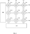
- FIG. 1 shows an exemplary embodiment of the invention.
- two or more row optical waveguides 102, 104, and 106 and two or more column optical waveguide 108, 110, and 112 are arranged in a planar array to define crossing sensors.
- Each crossing sensor includes one of the row waveguides in contact with one of the column waveguides at an intersection point.
- Each crossing sensor further includes a mechanical structure configured to enhance waveguide bending when pressure is applied to the crossing sensor.
- these mechanical structures are rigid rings 114a, 114b, 114c, 114d, 114e, 114f, 114g, 114h, and 114i.
- the optical waveguide pressure sensor array this provides is configured to sense pressure by providing light to the row optical waveguides with source electronics 118 and measuring light coupled to the column optical waveguides with detection electronics 116, or vice versa.
- the mechanical structure includes a rigid ring disposed in contact with one of the row or column optical waveguides and a hole of the rigid ring laterally encloses the intersection point of the crossing sensor, as shown on FIG. 1 .
- Suitable waveguides include, but are not limited to: step-index plastic fibers and graded-index plastic fibers.
- the optical coupling between the waveguides at the crossing sensors is a function of the local pressure, so by detecting the optical power received, the pressure on a crossing sensor can be measured. Because the optical coupling effect between transmitting and receiving waveguide is very small, high-sensitivity optical receivers are needed, using transimpedance amplifiers with high gain and a high input impedance. Sensitivity can be increased further by modulating each optical source with a low frequency carrier and applying highly-selective synchronous or lock-in detection, executed by multiplying the received amplified signal with the same carrier signal driving the LEDs and low-pass filtering the output. To achieve a simple and scalable system, a crossing sensor scanning method is preferred. Source electronics 118 selects only one row at a time to illuminate, and the crossings are scanned column by column by detection electronics 116. In this way, each crossing sensor is individually resolved and the combined results can provide a full 2-D pressure map.
- a local oscillator generates an electrical signal (e.g. a square wave) at a frequency f 0 , with which an array of M optical sources (e.g. LEDs) is modulated.
- an array of M optical sources e.g. LEDs
- this signal with frequency f 0 is fed to only one LED at a time, and each LED of the array is activated periodically (with a time period M ⁇ P/f 0 ).
- These LEDs each feed a transmission waveguide running along the cross-points in a column of the matrix.
- the receiving waveguides each running along a row of the matrix, each feed a photodetector (PD).
- the output signal of a PD is amplified, and then fed into a multiplier circuit where it is correlated with the signal from the local oscillator.
- the received signal from that PD can be measured by analog detection with high selectivity and sensitivity.
- binary detection of the activated cross-points can be done. Joint processing of the (binary) row-outputs and the (binary or analog) column-outputs provides the (row, column) position sensing information.
- FIG. 2 is a top view of a crossing sensor having a ring to enhance waveguide bending under pressure.
- 202 is a first rigid ring
- 206 is the receiving optical waveguide
- 204 is the transmitting optical waveguide.
- 206 can be the transmitting optical waveguide
- 204 can be the receiving optical waveguide.
- the inside edge of the hole of ring 202 is referenced as 208.
- waveguides at an angle of 90 degrees to each other are shown on FIG. 2 , other intersection angles are also usable.
- FIGs. 3A-B are side views showing operation of the crossing sensor of FIG. 2.
- FIG. 3A shows the configuration with no applied pressure.
- application of pressure block arrows on FIG. 3B
- the bending of the waveguide results in optical coupling at the waveguide crossing which is roughly proportional to the applied pressure. Bending the waveguide with a sufficiently small bend radius will slightly disrupt the confinement of the waveguide mode(s) (i.e., a small fraction of the light will leak through the cladding), and this is the physical effect relied upon here.
- the optical cross coupling is mainly due to bending of the transmitting and/or receiving waveguides. Bending enhances both light emitted from the transmitting waveguide and the ability of the receiving waveguide to couple incident light into its core.
- FIG. 4 shows a crossing sensor having two rigid rings sandwiching the waveguide intersection.
- a second rigid ring 402 having the inside edge of its hole referenced as 408 is disposed so that rings 302 and 402 sandwich the intersection point of the crossing sensor.
- the hole of the second rigid ring laterally encloses the intersection point of the crossing sensor.
- the holes of the first and second rigid rings have substantially the same size and shape, and are also substantially laterally aligned, as schematically shown on FIG. 4 . With this configuration, both waveguides have enhanced bending, thereby further increasing the cross-coupling.
- FIG. 5 shows an exemplary experimental setup for measuring waveguide cross coupling.
- Synchronous detection also known as lock-in detection
- 502 is the frequency reference
- 504 is the optical source
- 506 is the transmitting optical waveguide
- 508 is the receiving optical waveguide
- 510 (if present) is the mechanical structure for enhancing waveguide bending under pressure
- 512 is the optical detector
- 514 is a transimpedance amplifier
- 516 is a lock-in amplifier.
- waveguides 508 and 510 were standard PMMA (polymethylmethacrylate) step index POF (SI POF), with a fiber core diameter of 0.98 mm, fiber cladding diameter of 1.0 mm, and a Numerical Aperture of 0.5.
- Source 504 was a visible white light LED with an output power coupled into the SI-POF of about 3 mW. This light was modulated with a square wave signal with a frequency of 1000Hz from frequency reference 502.
- Detector 512 was a silicon photodiode and 516 was an EG&G Brookdeal 5206 Lock-in amplifier, which performed the amplification and synchronous detection operations.
- the rings 510 had an outside diameter of 50mm and an inside diameter of 8.5mm.
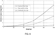
- FIG. 6 shows the voltage of the lock-in amplifier vs. the weight exerted to a crossing with: two rings, one ring and no rings.
- waveguide crossings There are various specific options for the configuration of the waveguide crossings. These will be discussed by way of examples where the waveguides are optical fibers, but the principles involve are more generally applicable.
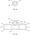
- FIG. 7A schematically shows a cross section of an optical fiber.
- 702 is the core
- 704 is the cladding
- 706 is the protective jacket. It is helpful to clearly understand the difference between cladding 704 and protective jacket 706, so we briefly review this distinction below.
- a waveguide has a core surrounded by a cladding to provide propagation of light confined mainly to the core. Although light does extend into the part of the cladding nearest the core (i.e., the evanescent tail of the waveguide mode(s)), the cladding is thick enough that a negligible faction (i.e., exponentially small) of the light normally reaches the outer surface of the cladding. Because the waveguide mode extends into the cladding, the cladding should have low optical loss. Note that a conventional optical fiber will often have a 3-layer construction of core, cladding and protective jacket, as on FIG. 7A . The protective jacket, if present, is not part of the cladding, because no significant part of the waveguide mode(s) extends into the protective jacket. Accordingly, the optical properties of the protective jacket are irrelevant, and it need not have low optical loss.
- FIG. 7B shows a preferred configuration for a crossing sensor having fibers.
- the first fiber has core 702, cladding 704 and protective jacket 706.
- the second fiber has core 712, cladding 714 and protective jacket 716.
- reflectors 720 and/or 722 e.g., aluminum foil
- the configuration of FIG. 7B has the protective jacket (706, 716) removed from both fibers at the crossing sensor.
- the cladding of both fibers (704, 714) is intact at the crossing sensor. This beneficially reduces the amount of work needed to fabricate a crossing sensor. More specifically, only the jacket needs to be removed. Nothing needs to be done to the cladding.
- One of the main points of this work is that sufficient waveguide cross-coupling can be obtained via waveguide bending even for waveguide crossings where the waveguide cladding is intact.
- step-index POF did not provide sufficient cross-coupling at waveguide crossings having intact cladding.
- Approaches were developed to increase cross-coupling in such cases, and these concepts were demonstrated in experiments using a light emitting diode (LED) as the source. Using an LED instead of a laser advantageously reduces cost.
- LED light emitting diode
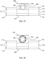
- FIGs. 7C and 7D These approaches for increasing cross-coupling may lead to improved performance in combination with enhanced waveguide bending as described herein. Accordingly, they are described below in connection with FIGs. 7C and 7D .
- a weight of 100g was detectable. This measured signal shows a clear reproducible and nearly linear relation to the weight pressure on the crossing sensor.
- FIG. 7C The configuration of FIG. 7C is similar to the configuration of FIG. 7B except that the cladding (704, 714) is removed from both fibers at the crossing sensor. Such removal of the cladding can be partial or complete ( FIG. 7C shows complete removal). Such partial or complete removal of the cladding can increase the cross-coupling provided by the crossing sensor under pressure.
- cladding 714 is removed at the crossing sensor, cladding 704 is intact at the crossing sensor, and cladding 704 is surrounded by a scatterer 730.
- Scatterer 730 serves to increase the fraction of light emitted from fiber core 712 (transmitting) that ends up in fiber core 702 (receiving).
- a small area of cladding 714 is removed so a small percentage ( ⁇ 0.1%) of the light in the core 712 can escape. Because of this small percentage, the optical power in the transmitting fiber is nearly constant over the whole length of the fiber (which is typically less than a few meters).
- the jacket or protective coating 706 of the receiving fiber is removed over a few centimeters and replaced by an elastic scattering non-absorbing primary coating 730. This is positioned such that the elastic scattering primary coating 730 of the receiving fiber can make physical contact to the core/cladding of the transmitting fiber at a fixed position.
- some light of the transmitting fiber which is coupled in the elastic scattering primary coating 730 of the receiving fiber may then transition via the cladding 704 into the core 702 of the receiving fiber.
- a reflective structure such as a reflective aluminum foil
- 720, 722 was added locally at the crossing sensor.
- some light gets from the transmitting fiber into the receiving fiber. The amount of this transitioning light depends upon the force exerted on the crossing sensor.
- a proof-of-principle setup has been realized to measure a pressure profile of a person lying on a mattress using fiber crossings as in FIG. 7D .
- Scanning i.e. the switching of the receiving fibers to a single photodiode
- the sensor grid was 8 transmitting and 8 receiving SI-POFs with a Numerical Aperture of 0.3, so the grid had 64 crossings.
- the distance between the fibers is 9cm so an area of about 70 x 70cm is covered.
- metal disks of 6 x 6cm are fixed at the POF crossings.
- This grid is put under a foam mattress of 180 x 80 x 16cm and 2D pressure profiles have been measured in three situations -- a person standing up on the mattress, lying on his back on the mattress, and lying on his right side. The measured pressure profiles clearly showed the position of the person on the mattress.
Landscapes
- Physics & Mathematics (AREA)
- General Physics & Mathematics (AREA)
- Engineering & Computer Science (AREA)
- Theoretical Computer Science (AREA)
- General Engineering & Computer Science (AREA)
- Chemical & Material Sciences (AREA)
- Nonlinear Science (AREA)
- Human Computer Interaction (AREA)
- Analytical Chemistry (AREA)
- Mathematical Physics (AREA)
- Crystallography & Structural Chemistry (AREA)
- Optics & Photonics (AREA)
- Measuring Fluid Pressure (AREA)
- Optical Couplings Of Light Guides (AREA)
- Force Measurement Appropriate To Specific Purposes (AREA)
Claims (9)
- Drucksensoranordnung für optische Wellenleiter, umfassend:zwei oder mehr optische Reihenwellenleiter (102, 104, 106);zwei oder mehr optische Spaltenwellenleiter (108, 110, 112), wobei die optischen Reihenwellenleiter (102, 104, 106) und die optischen Spaltenwellenleiter (108, 110, 112) in einer planaren Anordnung angeordnet sind, um Kreuzsensoren zu definieren, wobei jeder Kreuzsensor einen der Reihenwellenleiter (102, 104, 106) in Kontakt mit einem der Spaltenwellenleiter (108, 110, 112) an einem Schnittpunkt beinhaltet;wobei jeder Kreuzsensor ferner eine mechanische Struktur beinhaltet, die konfiguriert ist, um Wellenleiterbiegung zu verstärken, wenn Druck auf den Kreuzsensor ausgeübt wird, wobei die mechanische Struktur einen ersten starren Ring (202) beinhaltet, der in Kontakt mit einem von den optischen Reihen- oder Spaltenwellenleitern angeordnet ist, und ein Loch des ersten starren Rings (202) den Schnittpunkt des Kreuzsensors seitlich einschließt;wobei die Drucksensoranordnung für optische Wellenleiter konfiguriert ist, um Druck zu erfassen, indem den optischen Reihenwellenleitern Licht bereitgestellt wird und Licht gemessen wird, das an die optischen Spaltenwellenleiter gekoppelt ist, oder umgekehrt.
- Drucksensor für optische Wellenleiter nach Anspruch 1, wobei die mechanische Struktur ferner einen zweiten starren Ring (402) beinhaltet, der angeordnet ist, sodass der Schnittpunkt des Kreuzsensors vertikal zwischen dem ersten starren Ring (202) und dem zweiten starren Ring (402) eingefügt ist;
wobei ein Loch des zweiten starren Rings (402) den Schnittpunkt des Kreuzsensors seitlich einschließt. - Drucksensor für optische Wellenleiter nach Anspruch 2, wobei das Loch des ersten starren Rings (202) und das Loch des zweiten starren Rings (402) die gleiche Größe und Form aufweisen und seitlich ausgerichtet sind.
- Drucksensor für optische Wellenleiter nach Anspruch 1, wobei jeder optische Reihenwellenleiter einen Wellenleiterkern (702) beinhaltet, der von einer Wellenleiterummantelung (704) umgeben ist,
wobei jeder optische Spaltenwellenleiter einen Wellenleiterkern (702) beinhaltet, der von einer Wellenleiterummantelung (704) umgeben ist,
wobei die Wellenleiterummantelungen (704) sowohl von den optischen Reihenwellenleitern als auch den optischen Spaltenwellenleitern an einem oder mehreren der Kreuzsensoren intakt sind. - Drucksensor für optische Wellenleiter nach Anspruch 1, wobei jeder optische Reihenwellenleiter einen Wellenleiterkern (702) beinhaltet, der von einer Wellenleiterummantelung (704) umgeben ist,
wobei jeder optische Spaltenwellenleiter einen Wellenleiterkern (702) beinhaltet, der von einer Wellenleiterummantelung (704) umgeben ist,
wobei die Wellenleiterummantelungen (704) von einem oder von beiden von den optischen Reihenwellenleitern und den optischen Spaltenwellenleitern an einem oder mehreren der Kreuzsensoren zumindest teilweise entfernt sind. - Drucksensor für optische Wellenleiter nach Anspruch 1, wobei jeder optische Reihenwellenleiter eine optische Faser ist, die einen Wellenleiterkern (702) aufweist, der von einer Wellenleiterummantelung (704) umgeben ist, die von einem Schutzmantel (706) umgeben ist,
wobei jeder optische Spaltenwellenleiter eine optische Faser ist, die einen Wellenleiterkern (702) aufweist, der von einer Wellenleiterummantelung (704) umgeben ist, die von einem Schutzmantel (706) umgeben ist,
wobei die Schutzmäntel (706) sowohl von den optischen Reihenwellenleitern als auch den optischen Spaltenwellenleitern an einem oder mehreren der Kreuzsensoren entfernt sind. - Drucksensor für optische Wellenleiter nach Anspruch 1, wobei einer oder mehrere von den Kreuzsensoren ferner einen Reflektor (716) umfassen, um optische Kopplung zu erhöhen, wenn der Kreuzsensor unter Druck steht.
- Drucksensor für optische Wellenleiter nach Anspruch 1, wobei einer oder mehrere von den Kreuzsensoren ferner einen Streuer (730) umfassen, um optische Kopplung zu erhöhen, wenn der Kreuzsensor unter Druck steht.
- Drucksensor für optische Wellenleiter nach Anspruch 1, wobei die optischen Reihen- und Spaltenwellenleiter aus der Gruppe ausgewählt sind, die aus Folgendem besteht: Kunststofffasern mit Stufenindex und Kunststofffasern mit Gradientenindex.
Applications Claiming Priority (2)
| Application Number | Priority Date | Filing Date | Title |
|---|---|---|---|
| US201662300153P | 2016-02-26 | 2016-02-26 | |
| PCT/EP2017/054353 WO2017144675A1 (en) | 2016-02-26 | 2017-02-24 | Optical waveguide system for 2-dimensional location sensing |
Publications (2)
| Publication Number | Publication Date |
|---|---|
| EP3420331A1 EP3420331A1 (de) | 2019-01-02 |
| EP3420331B1 true EP3420331B1 (de) | 2021-04-07 |
Family
ID=58191416
Family Applications (1)
| Application Number | Title | Priority Date | Filing Date |
|---|---|---|---|
| EP17707807.8A Active EP3420331B1 (de) | 2016-02-26 | 2017-02-24 | Optisches wellenleitersystem für zweidimensionale positionserfassung |
Country Status (4)
| Country | Link |
|---|---|
| US (1) | US10768060B2 (de) |
| EP (1) | EP3420331B1 (de) |
| JP (1) | JP2019512773A (de) |
| WO (1) | WO2017144675A1 (de) |
Cited By (1)
| Publication number | Priority date | Publication date | Assignee | Title |
|---|---|---|---|---|
| DE102024001989A1 (de) * | 2024-06-18 | 2025-12-18 | HTWK Hochschule für Technik, Wirtschaft und Kultur Leipzig, Körperschaft des öffentlichen Rechts | Flächendrucksensor |
Families Citing this family (10)
| Publication number | Priority date | Publication date | Assignee | Title |
|---|---|---|---|---|
| WO2021256921A1 (en) * | 2020-06-14 | 2021-12-23 | Technische Universiteit Eindhoven | Two-dimensional optical waveguide pressure sensor array |
| CN117693670A (zh) * | 2021-08-20 | 2024-03-12 | 华为技术有限公司 | 一种触觉传感设备、检测方法以及装置 |
| WO2023064748A1 (en) * | 2021-10-15 | 2023-04-20 | Fiber Sense Limited | Scalable telecommunications geotechnical surveying |
| EP4220109B1 (de) * | 2022-02-01 | 2026-04-01 | Luxisens Technologies B.V. | Faseroptisches drucksensorarray oder -gitter zur orts-, vibrations- und/oder bewegungsmessung und matratze damit |
| CN115014623B (zh) * | 2022-06-10 | 2023-12-29 | 清华大学 | 光波导触觉传感器、传感系统、标定方法、及机器人 |
| EP4613187A1 (de) | 2024-03-07 | 2025-09-10 | Koninklijke Philips N.V. | Überwachung des patientenzustands in verbindung mit medizinischen eingriffen |
| EP4613188A1 (de) | 2024-03-07 | 2025-09-10 | Koninklijke Philips N.V. | Überwachung des patientenzustands während der medizinischen bildgebung |
| CN118129805B (zh) * | 2024-05-06 | 2024-09-13 | 天津工业大学 | 一种聚合物基环形谐振腔网状传感阵列多功能传感器 |
| EP4692744A1 (de) | 2024-08-07 | 2026-02-11 | Koninklijke Philips N.V. | Ausleseschaltung für ein druckmesssystem |
| EP4725394A1 (de) | 2024-10-08 | 2026-04-15 | Koninklijke Philips N.V. | Anpassung eines medizinischen bildgebungsverfahrens an patienteneigenschaften |
Citations (2)
| Publication number | Priority date | Publication date | Assignee | Title |
|---|---|---|---|---|
| EP0089237A2 (de) * | 1982-03-16 | 1983-09-21 | Unisys Corporation | Optischer Schalter mit Membrane und Tastatur auf einer Ebene |
| US4733068A (en) * | 1986-04-07 | 1988-03-22 | Rockwell International Corporation | Crossed fiber optic tactile sensor |
Family Cites Families (5)
| Publication number | Priority date | Publication date | Assignee | Title |
|---|---|---|---|---|
| GB2141821B (en) * | 1983-04-25 | 1986-05-29 | Gen Electric Plc | Pressure sensor |
| US7060964B1 (en) * | 2002-11-12 | 2006-06-13 | Ifos, Inc. | Reflection-mode fiber sensing devices |
| US7241986B2 (en) * | 2003-10-08 | 2007-07-10 | Mississippi State University | Fiber ringdown pressure/force sensors |
| US8209092B2 (en) * | 2007-03-23 | 2012-06-26 | Patricia Wiener | System and method for sensing loads |
| US9557846B2 (en) * | 2012-10-04 | 2017-01-31 | Corning Incorporated | Pressure-sensing touch system utilizing optical and capacitive systems |
-
2017
- 2017-02-24 EP EP17707807.8A patent/EP3420331B1/de active Active
- 2017-02-24 WO PCT/EP2017/054353 patent/WO2017144675A1/en not_active Ceased
- 2017-02-24 JP JP2018544926A patent/JP2019512773A/ja active Pending
- 2017-02-24 US US16/080,006 patent/US10768060B2/en active Active
Patent Citations (2)
| Publication number | Priority date | Publication date | Assignee | Title |
|---|---|---|---|---|
| EP0089237A2 (de) * | 1982-03-16 | 1983-09-21 | Unisys Corporation | Optischer Schalter mit Membrane und Tastatur auf einer Ebene |
| US4733068A (en) * | 1986-04-07 | 1988-03-22 | Rockwell International Corporation | Crossed fiber optic tactile sensor |
Cited By (3)
| Publication number | Priority date | Publication date | Assignee | Title |
|---|---|---|---|---|
| DE102024001989A1 (de) * | 2024-06-18 | 2025-12-18 | HTWK Hochschule für Technik, Wirtschaft und Kultur Leipzig, Körperschaft des öffentlichen Rechts | Flächendrucksensor |
| WO2025261546A1 (de) | 2024-06-18 | 2025-12-26 | Otto-von-Guericke-Universität Magdeburg, Körperschaft des öffentlichen Rechts | Flächendrucksensor |
| DE102024001989B4 (de) | 2024-06-18 | 2026-03-19 | HTWK Hochschule für Technik, Wirtschaft und Kultur Leipzig, Körperschaft des öffentlichen Rechts | Flächendrucksensor |
Also Published As
| Publication number | Publication date |
|---|---|
| US10768060B2 (en) | 2020-09-08 |
| JP2019512773A (ja) | 2019-05-16 |
| US20190064012A1 (en) | 2019-02-28 |
| EP3420331A1 (de) | 2019-01-02 |
| WO2017144675A1 (en) | 2017-08-31 |
Similar Documents
| Publication | Publication Date | Title |
|---|---|---|
| EP3420331B1 (de) | Optisches wellenleitersystem für zweidimensionale positionserfassung | |
| US4734577A (en) | Continuous strain measurement along a span | |
| US4692610A (en) | Fiber optic aircraft load relief control system | |
| EP0007312B1 (de) | Optisches messgerät | |
| US10634551B2 (en) | Reflectometric vibration measurement system and relative method for monitoring multiphase flows | |
| US4947693A (en) | Discrete strain sensor | |
| DE60039172D1 (de) | Integrierender sensor mit mehreren wellenleitern | |
| EP3144633B1 (de) | Faser-bragg-gitter-abfrageanordnung und verfahren dafür | |
| CN102292621A (zh) | 分布式光纤感测中的改进 | |
| EP1203211B1 (de) | Verfahren und vorrichtung für faseroptische messsysteme | |
| US4717253A (en) | Optical strain gauge | |
| US6144790A (en) | Contact fiber optic impact sensor | |
| EP3384248B1 (de) | Optische messvorrichtung mit einem interrogator und einem monomodem polymerbasierten faseroptischen sensorsystem | |
| KR20190006659A (ko) | 브릴루앙 산란을 이용한 형상 센싱 장치, 방법 및 시스템 | |
| GB2091874A (en) | Intruder detection system | |
| EP2144207A1 (de) | Glasfasereindringungsschutzsystem | |
| EP1969323A1 (de) | Optoelektronisches system und verfahren zum detektieren von störungen | |
| JP2017116531A (ja) | 薄膜光センシングネットワークを用いた触覚センシングシステム及び方法 | |
| Arute et al. | Time–space–weight calibrated plastic optical fiber-based pressure sensing carpet | |
| US5446278A (en) | Fiber optic sensor employing successively destroyed coupled points or reflectors for detecting shock wave speed and damage location | |
| KR200259974Y1 (ko) | 침입자 감시용 광섬유 센서 시스템 | |
| KR20140128508A (ko) | 광섬유를 이용한 사면붕괴 방지시스템 | |
| KR101953281B1 (ko) | 설치 및 환경에 의한 오차가 없는 광섬유 센서를 이용한 센싱시스템 | |
| van den Boom¹ et al. | Optical Coupling between Crossing Polymer Optical Fibres | |
| GB2166864A (en) | Magnetometer |
Legal Events
| Date | Code | Title | Description |
|---|---|---|---|
| STAA | Information on the status of an ep patent application or granted ep patent |
Free format text: STATUS: UNKNOWN |
|
| STAA | Information on the status of an ep patent application or granted ep patent |
Free format text: STATUS: THE INTERNATIONAL PUBLICATION HAS BEEN MADE |
|
| PUAI | Public reference made under article 153(3) epc to a published international application that has entered the european phase |
Free format text: ORIGINAL CODE: 0009012 |
|
| STAA | Information on the status of an ep patent application or granted ep patent |
Free format text: STATUS: REQUEST FOR EXAMINATION WAS MADE |
|
| 17P | Request for examination filed |
Effective date: 20180823 |
|
| AK | Designated contracting states |
Kind code of ref document: A1 Designated state(s): AL AT BE BG CH CY CZ DE DK EE ES FI FR GB GR HR HU IE IS IT LI LT LU LV MC MK MT NL NO PL PT RO RS SE SI SK SM TR |
|
| AX | Request for extension of the european patent |
Extension state: BA ME |
|
| DAV | Request for validation of the european patent (deleted) | ||
| DAX | Request for extension of the european patent (deleted) | ||
| STAA | Information on the status of an ep patent application or granted ep patent |
Free format text: STATUS: EXAMINATION IS IN PROGRESS |
|
| 17Q | First examination report despatched |
Effective date: 20190916 |
|
| GRAP | Despatch of communication of intention to grant a patent |
Free format text: ORIGINAL CODE: EPIDOSNIGR1 |
|
| STAA | Information on the status of an ep patent application or granted ep patent |
Free format text: STATUS: GRANT OF PATENT IS INTENDED |
|
| RIC1 | Information provided on ipc code assigned before grant |
Ipc: G01L 1/24 20060101ALI20200907BHEP Ipc: G01L 5/22 20060101AFI20200907BHEP Ipc: G06F 3/042 20060101ALI20200907BHEP Ipc: G02F 1/1333 20060101ALI20200907BHEP Ipc: B25J 13/08 20060101ALI20200907BHEP |
|
| INTG | Intention to grant announced |
Effective date: 20201012 |
|
| GRAS | Grant fee paid |
Free format text: ORIGINAL CODE: EPIDOSNIGR3 |
|
| GRAA | (expected) grant |
Free format text: ORIGINAL CODE: 0009210 |
|
| STAA | Information on the status of an ep patent application or granted ep patent |
Free format text: STATUS: THE PATENT HAS BEEN GRANTED |
|
| AK | Designated contracting states |
Kind code of ref document: B1 Designated state(s): AL AT BE BG CH CY CZ DE DK EE ES FI FR GB GR HR HU IE IS IT LI LT LU LV MC MK MT NL NO PL PT RO RS SE SI SK SM TR |
|
| REG | Reference to a national code |
Ref country code: GB Ref legal event code: FG4D |
|
| REG | Reference to a national code |
Ref country code: AT Ref legal event code: REF Ref document number: 1380292 Country of ref document: AT Kind code of ref document: T Effective date: 20210415 Ref country code: CH Ref legal event code: EP |
|
| REG | Reference to a national code |
Ref country code: DE Ref legal event code: R096 Ref document number: 602017036124 Country of ref document: DE |
|
| REG | Reference to a national code |
Ref country code: IE Ref legal event code: FG4D |
|
| REG | Reference to a national code |
Ref country code: LT Ref legal event code: MG9D |
|
| REG | Reference to a national code |
Ref country code: NL Ref legal event code: MP Effective date: 20210407 Ref country code: AT Ref legal event code: MK05 Ref document number: 1380292 Country of ref document: AT Kind code of ref document: T Effective date: 20210407 |
|
| PG25 | Lapsed in a contracting state [announced via postgrant information from national office to epo] |
Ref country code: FI Free format text: LAPSE BECAUSE OF FAILURE TO SUBMIT A TRANSLATION OF THE DESCRIPTION OR TO PAY THE FEE WITHIN THE PRESCRIBED TIME-LIMIT Effective date: 20210407 Ref country code: LT Free format text: LAPSE BECAUSE OF FAILURE TO SUBMIT A TRANSLATION OF THE DESCRIPTION OR TO PAY THE FEE WITHIN THE PRESCRIBED TIME-LIMIT Effective date: 20210407 Ref country code: NL Free format text: LAPSE BECAUSE OF FAILURE TO SUBMIT A TRANSLATION OF THE DESCRIPTION OR TO PAY THE FEE WITHIN THE PRESCRIBED TIME-LIMIT Effective date: 20210407 Ref country code: HR Free format text: LAPSE BECAUSE OF FAILURE TO SUBMIT A TRANSLATION OF THE DESCRIPTION OR TO PAY THE FEE WITHIN THE PRESCRIBED TIME-LIMIT Effective date: 20210407 Ref country code: BG Free format text: LAPSE BECAUSE OF FAILURE TO SUBMIT A TRANSLATION OF THE DESCRIPTION OR TO PAY THE FEE WITHIN THE PRESCRIBED TIME-LIMIT Effective date: 20210707 Ref country code: AT Free format text: LAPSE BECAUSE OF FAILURE TO SUBMIT A TRANSLATION OF THE DESCRIPTION OR TO PAY THE FEE WITHIN THE PRESCRIBED TIME-LIMIT Effective date: 20210407 |
|
| PG25 | Lapsed in a contracting state [announced via postgrant information from national office to epo] |
Ref country code: IS Free format text: LAPSE BECAUSE OF FAILURE TO SUBMIT A TRANSLATION OF THE DESCRIPTION OR TO PAY THE FEE WITHIN THE PRESCRIBED TIME-LIMIT Effective date: 20210807 Ref country code: LV Free format text: LAPSE BECAUSE OF FAILURE TO SUBMIT A TRANSLATION OF THE DESCRIPTION OR TO PAY THE FEE WITHIN THE PRESCRIBED TIME-LIMIT Effective date: 20210407 Ref country code: GR Free format text: LAPSE BECAUSE OF FAILURE TO SUBMIT A TRANSLATION OF THE DESCRIPTION OR TO PAY THE FEE WITHIN THE PRESCRIBED TIME-LIMIT Effective date: 20210708 Ref country code: SE Free format text: LAPSE BECAUSE OF FAILURE TO SUBMIT A TRANSLATION OF THE DESCRIPTION OR TO PAY THE FEE WITHIN THE PRESCRIBED TIME-LIMIT Effective date: 20210407 Ref country code: RS Free format text: LAPSE BECAUSE OF FAILURE TO SUBMIT A TRANSLATION OF THE DESCRIPTION OR TO PAY THE FEE WITHIN THE PRESCRIBED TIME-LIMIT Effective date: 20210407 Ref country code: PL Free format text: LAPSE BECAUSE OF FAILURE TO SUBMIT A TRANSLATION OF THE DESCRIPTION OR TO PAY THE FEE WITHIN THE PRESCRIBED TIME-LIMIT Effective date: 20210407 Ref country code: NO Free format text: LAPSE BECAUSE OF FAILURE TO SUBMIT A TRANSLATION OF THE DESCRIPTION OR TO PAY THE FEE WITHIN THE PRESCRIBED TIME-LIMIT Effective date: 20210707 Ref country code: PT Free format text: LAPSE BECAUSE OF FAILURE TO SUBMIT A TRANSLATION OF THE DESCRIPTION OR TO PAY THE FEE WITHIN THE PRESCRIBED TIME-LIMIT Effective date: 20210809 |
|
| REG | Reference to a national code |
Ref country code: DE Ref legal event code: R097 Ref document number: 602017036124 Country of ref document: DE |
|
| PG25 | Lapsed in a contracting state [announced via postgrant information from national office to epo] |
Ref country code: RO Free format text: LAPSE BECAUSE OF FAILURE TO SUBMIT A TRANSLATION OF THE DESCRIPTION OR TO PAY THE FEE WITHIN THE PRESCRIBED TIME-LIMIT Effective date: 20210407 Ref country code: ES Free format text: LAPSE BECAUSE OF FAILURE TO SUBMIT A TRANSLATION OF THE DESCRIPTION OR TO PAY THE FEE WITHIN THE PRESCRIBED TIME-LIMIT Effective date: 20210407 Ref country code: DK Free format text: LAPSE BECAUSE OF FAILURE TO SUBMIT A TRANSLATION OF THE DESCRIPTION OR TO PAY THE FEE WITHIN THE PRESCRIBED TIME-LIMIT Effective date: 20210407 Ref country code: CZ Free format text: LAPSE BECAUSE OF FAILURE TO SUBMIT A TRANSLATION OF THE DESCRIPTION OR TO PAY THE FEE WITHIN THE PRESCRIBED TIME-LIMIT Effective date: 20210407 Ref country code: EE Free format text: LAPSE BECAUSE OF FAILURE TO SUBMIT A TRANSLATION OF THE DESCRIPTION OR TO PAY THE FEE WITHIN THE PRESCRIBED TIME-LIMIT Effective date: 20210407 Ref country code: SM Free format text: LAPSE BECAUSE OF FAILURE TO SUBMIT A TRANSLATION OF THE DESCRIPTION OR TO PAY THE FEE WITHIN THE PRESCRIBED TIME-LIMIT Effective date: 20210407 Ref country code: SK Free format text: LAPSE BECAUSE OF FAILURE TO SUBMIT A TRANSLATION OF THE DESCRIPTION OR TO PAY THE FEE WITHIN THE PRESCRIBED TIME-LIMIT Effective date: 20210407 |
|
| PLBE | No opposition filed within time limit |
Free format text: ORIGINAL CODE: 0009261 |
|
| STAA | Information on the status of an ep patent application or granted ep patent |
Free format text: STATUS: NO OPPOSITION FILED WITHIN TIME LIMIT |
|
| 26N | No opposition filed |
Effective date: 20220110 |
|
| PG25 | Lapsed in a contracting state [announced via postgrant information from national office to epo] |
Ref country code: IS Free format text: LAPSE BECAUSE OF FAILURE TO SUBMIT A TRANSLATION OF THE DESCRIPTION OR TO PAY THE FEE WITHIN THE PRESCRIBED TIME-LIMIT Effective date: 20210807 Ref country code: AL Free format text: LAPSE BECAUSE OF FAILURE TO SUBMIT A TRANSLATION OF THE DESCRIPTION OR TO PAY THE FEE WITHIN THE PRESCRIBED TIME-LIMIT Effective date: 20210407 |
|
| PG25 | Lapsed in a contracting state [announced via postgrant information from national office to epo] |
Ref country code: IT Free format text: LAPSE BECAUSE OF FAILURE TO SUBMIT A TRANSLATION OF THE DESCRIPTION OR TO PAY THE FEE WITHIN THE PRESCRIBED TIME-LIMIT Effective date: 20210407 |
|
| REG | Reference to a national code |
Ref country code: LU Ref legal event code: PD Owner name: LUXISENS TECHNOLOGIES B.V.; NL Free format text: FORMER OWNER: TECHNISCHE UNIVERSITEIT EINDHOVEN Effective date: 20220816 Ref country code: LU Ref legal event code: HC Owner name: TECHNISCHE UNIVERSITEIT EINDHOVEN; NL Free format text: FORMER OWNER: TECHNISCHE UNIVERSITEIT EINDHOVEN Effective date: 20220816 |
|
| PG25 | Lapsed in a contracting state [announced via postgrant information from national office to epo] |
Ref country code: MC Free format text: LAPSE BECAUSE OF FAILURE TO SUBMIT A TRANSLATION OF THE DESCRIPTION OR TO PAY THE FEE WITHIN THE PRESCRIBED TIME-LIMIT Effective date: 20210407 |
|
| REG | Reference to a national code |
Ref country code: CH Ref legal event code: PL |
|
| REG | Reference to a national code |
Ref country code: BE Ref legal event code: MM Effective date: 20220228 |
|
| PG25 | Lapsed in a contracting state [announced via postgrant information from national office to epo] |
Ref country code: LU Free format text: LAPSE BECAUSE OF NON-PAYMENT OF DUE FEES Effective date: 20220224 |
|
| REG | Reference to a national code |
Ref country code: GB Ref legal event code: 732E Free format text: REGISTERED BETWEEN 20221117 AND 20221123 |
|
| PG25 | Lapsed in a contracting state [announced via postgrant information from national office to epo] |
Ref country code: IE Free format text: LAPSE BECAUSE OF NON-PAYMENT OF DUE FEES Effective date: 20220224 |
|
| PG25 | Lapsed in a contracting state [announced via postgrant information from national office to epo] |
Ref country code: BE Free format text: LAPSE BECAUSE OF NON-PAYMENT OF DUE FEES Effective date: 20220228 |
|
| P01 | Opt-out of the competence of the unified patent court (upc) registered |
Effective date: 20230731 |
|
| PG25 | Lapsed in a contracting state [announced via postgrant information from national office to epo] |
Ref country code: HU Free format text: LAPSE BECAUSE OF FAILURE TO SUBMIT A TRANSLATION OF THE DESCRIPTION OR TO PAY THE FEE WITHIN THE PRESCRIBED TIME-LIMIT; INVALID AB INITIO Effective date: 20170224 |
|
| PG25 | Lapsed in a contracting state [announced via postgrant information from national office to epo] |
Ref country code: MK Free format text: LAPSE BECAUSE OF FAILURE TO SUBMIT A TRANSLATION OF THE DESCRIPTION OR TO PAY THE FEE WITHIN THE PRESCRIBED TIME-LIMIT Effective date: 20210407 Ref country code: CY Free format text: LAPSE BECAUSE OF FAILURE TO SUBMIT A TRANSLATION OF THE DESCRIPTION OR TO PAY THE FEE WITHIN THE PRESCRIBED TIME-LIMIT Effective date: 20210407 |
|
| PG25 | Lapsed in a contracting state [announced via postgrant information from national office to epo] |
Ref country code: MT Free format text: LAPSE BECAUSE OF FAILURE TO SUBMIT A TRANSLATION OF THE DESCRIPTION OR TO PAY THE FEE WITHIN THE PRESCRIBED TIME-LIMIT Effective date: 20210407 |
|
| PG25 | Lapsed in a contracting state [announced via postgrant information from national office to epo] |
Ref country code: TR Free format text: LAPSE BECAUSE OF FAILURE TO SUBMIT A TRANSLATION OF THE DESCRIPTION OR TO PAY THE FEE WITHIN THE PRESCRIBED TIME-LIMIT Effective date: 20210407 |
|
| REG | Reference to a national code |
Ref country code: CH Ref legal event code: U11 Free format text: ST27 STATUS EVENT CODE: U-0-0-U10-U11 (AS PROVIDED BY THE NATIONAL OFFICE) Effective date: 20260326 |
|
| PGFP | Annual fee paid to national office [announced via postgrant information from national office to epo] |
Ref country code: GB Payment date: 20260324 Year of fee payment: 10 |
|
| PGFP | Annual fee paid to national office [announced via postgrant information from national office to epo] |
Ref country code: DE Payment date: 20260224 Year of fee payment: 10 |
|
| PGFP | Annual fee paid to national office [announced via postgrant information from national office to epo] |
Ref country code: FR Payment date: 20260226 Year of fee payment: 10 |
|
| PGFP | Annual fee paid to national office [announced via postgrant information from national office to epo] |
Ref country code: CH Payment date: 20260326 Year of fee payment: 10 |