EP3420281B1 - System, verfahren und computerprogrammprodukt zur luftfilterverwaltung - Google Patents
System, verfahren und computerprogrammprodukt zur luftfilterverwaltung Download PDFInfo
- Publication number
- EP3420281B1 EP3420281B1 EP17712256.1A EP17712256A EP3420281B1 EP 3420281 B1 EP3420281 B1 EP 3420281B1 EP 17712256 A EP17712256 A EP 17712256A EP 3420281 B1 EP3420281 B1 EP 3420281B1
- Authority
- EP
- European Patent Office
- Prior art keywords
- air filter
- air
- filter
- arrangement
- sensor
- Prior art date
- Legal status (The legal status is an assumption and is not a legal conclusion. Google has not performed a legal analysis and makes no representation as to the accuracy of the status listed.)
- Active
Links
- 238000000034 method Methods 0.000 title claims description 30
- 238000004590 computer program Methods 0.000 title claims description 10
- 238000009434 installation Methods 0.000 claims description 76
- 238000002485 combustion reaction Methods 0.000 claims description 29
- 238000004891 communication Methods 0.000 claims description 24
- 239000000428 dust Substances 0.000 claims description 22
- 238000012545 processing Methods 0.000 claims description 14
- 238000011109 contamination Methods 0.000 claims description 9
- 239000011236 particulate material Substances 0.000 claims description 5
- 239000003570 air Substances 0.000 description 394
- 238000007726 management method Methods 0.000 description 28
- 239000002245 particle Substances 0.000 description 20
- 230000008901 benefit Effects 0.000 description 13
- 238000010586 diagram Methods 0.000 description 12
- 239000012080 ambient air Substances 0.000 description 11
- 239000000356 contaminant Substances 0.000 description 7
- 238000011144 upstream manufacturing Methods 0.000 description 7
- 230000008859 change Effects 0.000 description 6
- 230000000875 corresponding effect Effects 0.000 description 6
- 238000001914 filtration Methods 0.000 description 6
- 230000008569 process Effects 0.000 description 6
- 230000015556 catabolic process Effects 0.000 description 5
- 238000006731 degradation reaction Methods 0.000 description 5
- 230000007613 environmental effect Effects 0.000 description 5
- 238000004519 manufacturing process Methods 0.000 description 5
- CURLTUGMZLYLDI-UHFFFAOYSA-N Carbon dioxide Chemical compound O=C=O CURLTUGMZLYLDI-UHFFFAOYSA-N 0.000 description 4
- 230000005540 biological transmission Effects 0.000 description 4
- 238000005259 measurement Methods 0.000 description 4
- 230000009467 reduction Effects 0.000 description 4
- 238000000926 separation method Methods 0.000 description 4
- 230000002596 correlated effect Effects 0.000 description 3
- 238000005265 energy consumption Methods 0.000 description 3
- 239000000463 material Substances 0.000 description 3
- 150000003839 salts Chemical class 0.000 description 3
- 239000000523 sample Substances 0.000 description 3
- 238000009423 ventilation Methods 0.000 description 3
- 229910002092 carbon dioxide Inorganic materials 0.000 description 2
- 239000001569 carbon dioxide Substances 0.000 description 2
- 238000007728 cost analysis Methods 0.000 description 2
- 238000005516 engineering process Methods 0.000 description 2
- 238000003860 storage Methods 0.000 description 2
- 241000238631 Hexapoda Species 0.000 description 1
- FAPWRFPIFSIZLT-UHFFFAOYSA-M Sodium chloride Chemical compound [Na+].[Cl-] FAPWRFPIFSIZLT-UHFFFAOYSA-M 0.000 description 1
- 230000004931 aggregating effect Effects 0.000 description 1
- 230000002776 aggregation Effects 0.000 description 1
- 238000004220 aggregation Methods 0.000 description 1
- 230000001143 conditioned effect Effects 0.000 description 1
- 230000003750 conditioning effect Effects 0.000 description 1
- 238000013500 data storage Methods 0.000 description 1
- 230000002950 deficient Effects 0.000 description 1
- 238000013461 design Methods 0.000 description 1
- 230000002542 deteriorative effect Effects 0.000 description 1
- 230000001627 detrimental effect Effects 0.000 description 1
- 230000003467 diminishing effect Effects 0.000 description 1
- 238000009826 distribution Methods 0.000 description 1
- 230000000694 effects Effects 0.000 description 1
- 238000011156 evaluation Methods 0.000 description 1
- 239000000446 fuel Substances 0.000 description 1
- 230000006870 function Effects 0.000 description 1
- 238000012804 iterative process Methods 0.000 description 1
- 230000007774 longterm Effects 0.000 description 1
- 238000012423 maintenance Methods 0.000 description 1
- 238000012544 monitoring process Methods 0.000 description 1
- 238000005457 optimization Methods 0.000 description 1
- 230000000717 retained effect Effects 0.000 description 1
- 239000004576 sand Substances 0.000 description 1
- 239000011780 sodium chloride Substances 0.000 description 1
- 238000012546 transfer Methods 0.000 description 1
- 230000000007 visual effect Effects 0.000 description 1
Images


Classifications
-
- F—MECHANICAL ENGINEERING; LIGHTING; HEATING; WEAPONS; BLASTING
- F24—HEATING; RANGES; VENTILATING
- F24F—AIR-CONDITIONING; AIR-HUMIDIFICATION; VENTILATION; USE OF AIR CURRENTS FOR SCREENING
- F24F11/00—Control or safety arrangements
- F24F11/30—Control or safety arrangements for purposes related to the operation of the system, e.g. for safety or monitoring
- F24F11/32—Responding to malfunctions or emergencies
- F24F11/39—Monitoring filter performance
-
- F—MECHANICAL ENGINEERING; LIGHTING; HEATING; WEAPONS; BLASTING
- F24—HEATING; RANGES; VENTILATING
- F24F—AIR-CONDITIONING; AIR-HUMIDIFICATION; VENTILATION; USE OF AIR CURRENTS FOR SCREENING
- F24F11/00—Control or safety arrangements
- F24F11/30—Control or safety arrangements for purposes related to the operation of the system, e.g. for safety or monitoring
-
- B—PERFORMING OPERATIONS; TRANSPORTING
- B01—PHYSICAL OR CHEMICAL PROCESSES OR APPARATUS IN GENERAL
- B01D—SEPARATION
- B01D35/00—Filtering devices having features not specifically covered by groups B01D24/00 - B01D33/00, or for applications not specifically covered by groups B01D24/00 - B01D33/00; Auxiliary devices for filtration; Filter housing constructions
- B01D35/14—Safety devices specially adapted for filtration; Devices for indicating clogging
- B01D35/143—Filter condition indicators
-
- B—PERFORMING OPERATIONS; TRANSPORTING
- B01—PHYSICAL OR CHEMICAL PROCESSES OR APPARATUS IN GENERAL
- B01D—SEPARATION
- B01D46/00—Filters or filtering processes specially modified for separating dispersed particles from gases or vapours
- B01D46/0084—Filters or filtering processes specially modified for separating dispersed particles from gases or vapours provided with safety means
- B01D46/0086—Filter condition indicators
-
- B—PERFORMING OPERATIONS; TRANSPORTING
- B01—PHYSICAL OR CHEMICAL PROCESSES OR APPARATUS IN GENERAL
- B01D—SEPARATION
- B01D46/00—Filters or filtering processes specially modified for separating dispersed particles from gases or vapours
- B01D46/42—Auxiliary equipment or operation thereof
- B01D46/44—Auxiliary equipment or operation thereof controlling filtration
- B01D46/46—Auxiliary equipment or operation thereof controlling filtration automatic
-
- F—MECHANICAL ENGINEERING; LIGHTING; HEATING; WEAPONS; BLASTING
- F02—COMBUSTION ENGINES; HOT-GAS OR COMBUSTION-PRODUCT ENGINE PLANTS
- F02C—GAS-TURBINE PLANTS; AIR INTAKES FOR JET-PROPULSION PLANTS; CONTROLLING FUEL SUPPLY IN AIR-BREATHING JET-PROPULSION PLANTS
- F02C7/00—Features, components parts, details or accessories, not provided for in, or of interest apart form groups F02C1/00 - F02C6/00; Air intakes for jet-propulsion plants
- F02C7/04—Air intakes for gas-turbine plants or jet-propulsion plants
- F02C7/05—Air intakes for gas-turbine plants or jet-propulsion plants having provisions for obviating the penetration of damaging objects or particles
- F02C7/052—Air intakes for gas-turbine plants or jet-propulsion plants having provisions for obviating the penetration of damaging objects or particles with dust-separation devices
-
- F—MECHANICAL ENGINEERING; LIGHTING; HEATING; WEAPONS; BLASTING
- F24—HEATING; RANGES; VENTILATING
- F24F—AIR-CONDITIONING; AIR-HUMIDIFICATION; VENTILATION; USE OF AIR CURRENTS FOR SCREENING
- F24F11/00—Control or safety arrangements
- F24F11/62—Control or safety arrangements characterised by the type of control or by internal processing, e.g. using fuzzy logic, adaptive control or estimation of values
- F24F11/63—Electronic processing
-
- F—MECHANICAL ENGINEERING; LIGHTING; HEATING; WEAPONS; BLASTING
- F24—HEATING; RANGES; VENTILATING
- F24F—AIR-CONDITIONING; AIR-HUMIDIFICATION; VENTILATION; USE OF AIR CURRENTS FOR SCREENING
- F24F8/00—Treatment, e.g. purification, of air supplied to human living or working spaces otherwise than by heating, cooling, humidifying or drying
- F24F8/10—Treatment, e.g. purification, of air supplied to human living or working spaces otherwise than by heating, cooling, humidifying or drying by separation, e.g. by filtering
- F24F8/108—Treatment, e.g. purification, of air supplied to human living or working spaces otherwise than by heating, cooling, humidifying or drying by separation, e.g. by filtering using dry filter elements
-
- B—PERFORMING OPERATIONS; TRANSPORTING
- B01—PHYSICAL OR CHEMICAL PROCESSES OR APPARATUS IN GENERAL
- B01D—SEPARATION
- B01D2279/00—Filters adapted for separating dispersed particles from gases or vapours specially modified for specific uses
- B01D2279/60—Filters adapted for separating dispersed particles from gases or vapours specially modified for specific uses for the intake of internal combustion engines or turbines
-
- F—MECHANICAL ENGINEERING; LIGHTING; HEATING; WEAPONS; BLASTING
- F05—INDEXING SCHEMES RELATING TO ENGINES OR PUMPS IN VARIOUS SUBCLASSES OF CLASSES F01-F04
- F05D—INDEXING SCHEME FOR ASPECTS RELATING TO NON-POSITIVE-DISPLACEMENT MACHINES OR ENGINES, GAS-TURBINES OR JET-PROPULSION PLANTS
- F05D2260/00—Function
- F05D2260/60—Fluid transfer
- F05D2260/607—Preventing clogging or obstruction of flow paths by dirt, dust, or foreign particles
-
- F—MECHANICAL ENGINEERING; LIGHTING; HEATING; WEAPONS; BLASTING
- F24—HEATING; RANGES; VENTILATING
- F24F—AIR-CONDITIONING; AIR-HUMIDIFICATION; VENTILATION; USE OF AIR CURRENTS FOR SCREENING
- F24F2110/00—Control inputs relating to air properties
- F24F2110/50—Air quality properties
-
- F—MECHANICAL ENGINEERING; LIGHTING; HEATING; WEAPONS; BLASTING
- F24—HEATING; RANGES; VENTILATING
- F24F—AIR-CONDITIONING; AIR-HUMIDIFICATION; VENTILATION; USE OF AIR CURRENTS FOR SCREENING
- F24F2110/00—Control inputs relating to air properties
- F24F2110/50—Air quality properties
- F24F2110/52—Air quality properties of the outside air
-
- Y—GENERAL TAGGING OF NEW TECHNOLOGICAL DEVELOPMENTS; GENERAL TAGGING OF CROSS-SECTIONAL TECHNOLOGIES SPANNING OVER SEVERAL SECTIONS OF THE IPC; TECHNICAL SUBJECTS COVERED BY FORMER USPC CROSS-REFERENCE ART COLLECTIONS [XRACs] AND DIGESTS
- Y02—TECHNOLOGIES OR APPLICATIONS FOR MITIGATION OR ADAPTATION AGAINST CLIMATE CHANGE
- Y02B—CLIMATE CHANGE MITIGATION TECHNOLOGIES RELATED TO BUILDINGS, e.g. HOUSING, HOUSE APPLIANCES OR RELATED END-USER APPLICATIONS
- Y02B30/00—Energy efficient heating, ventilation or air conditioning [HVAC]
- Y02B30/70—Efficient control or regulation technologies, e.g. for control of refrigerant flow, motor or heating
Definitions
- the present invention relates to a system, method and computer program product for air filter management of an air filter arrangement in an air flow inlet to an industrial installation.
- filters in such arrangements gradually accumulate matter from the air and as this matter accumulates on the filter the resistance to flow of air through the filter increases.
- Industrial filter arrangements are clogged up by particles trapped in the air filters but also by environmental conditions such as fog, rain, snow, and the like. The clogging may reduce filtration and operating efficiency while increasing the overall pressure drop.
- An increase of the pressure drop over the filter arrangement implies an inlet air pressure loss that may affect the operation and performance of the industrial installation.
- a plurality of air filters are arranged in a sequential set up.
- the first filter is usually a coarse filter arranged to remove larger particles in the air.
- the pressure drop increase over such a coarse filter may be insignificant.
- An intermediary filter may be arranged to protect the air flow inlet from mid-size particles.
- the air quality reaching the industrial installation, e.g., a turbine, is determined through the use of a final filter arranged to collect particles of smaller sizes, e.g. saline particles.
- Combustion turbine power plants e.g., gas turbine power plants
- gas turbine power plants are examples of industrial installations that require a large supply of intake air to support the combustion process.
- Other examples worth mentioning are turbine powered compressor stations or turbine powered mechanical drives.
- air filter arrangements are provided at the air flow inlet to the combustion turbine.
- a filter has a certain lifespan during which it functions adequately.
- the lifespan depends on different factors such as particle density in the air, the flow of air etc.
- the filters should be used as long as possible until their technical lifetime has come to an end, e.g., at a time when a pressure loss over the filter results in inadequate air supply in support of the combustion process.
- US6009404 discloses a method and device for cost-oriented monitoring operation of a filter arrangement.
- a plurality of sensors is used to obtain information relevant for determining an operating state of the filter.
- An evaluation unit is provided wherein information gathered in the sensors is processed and used to determine operating costs associated with the determined operating state of the filter.
- SE537506 describes a method of determining an optimal time for operating a filter in a ventilation system in order to save costs and leave as little carbon dioxide footprint as possible. The method is based on obtaining information on environmental impact for manufacturing a new filter, information on environmental impact from using the present filter and information relevant for determining an operating state of a filter. An optimal lifetime for a filter in the ventilation system is determined based on this information. Thus, a life-cycle cost analysis is provided wherein environmental aspects are taken into account.
- the optimal filter use time is based on estimates from current conditions in the specific industrial installation. Current conditions may be established with high accuracy, but there is a lack of actual data for continued operation of the filter arrangements and estimates for future operating states of the industrial installation may be quite unreliable.
- the main problem when using a filter with an inadequate operating state is not the increase of energy consumption for operating the combustion turbine, but a reduction in the output of the turbine. The impact of such a reduction in the output of the turbine is so significant that even a fairly moderate reduction in the operating state of a filter, may imply a high loss in production for a plant owner.
- Another problem for the plant owner is that an exchange of filter may require reduced operation during the time needed for the filter exchange.
- the proposed solutions enable improved air filter management in that improved estimates for a technical lifetime, life expectancy, and lifecycle costs are generated and in that operators may gain an improved understanding of cost of filter replacement versus the cost of maintaining a filter when filter capacity has started to deteriorate.
- a system comprises air filter devices and an air filter control station.
- Each air filter device is provided at an air filter arrangement in an air flow inlet to an industrial installation; the air filter arrangement comprising at least one filter medium capable of removing particulate material and/or airborne molecular contamination, AMC, from an air flow received at the air flow inlet.
- Each air filter device comprises a set of sensors arranged to gather sensor data representative of an operating state of the air filter arrangement, a microprocessor arranged to determine operating state information for the air filter arrangement based on the gathered sensor data, and a communication unit arranged to transmit the operating state information.
- the air filter control station comprises a communication unit arranged to receive operating state information from a plurality of air filter devices and a user interface for selecting an air filter arrangement.
- the air filter control station also comprises processing circuitry arranged to estimate a life expectancy of the selected air filter arrangement based on operating state information received from an air filter device provided at the selected air filter arrangement and operating state information received from one or more other air filter devices provided at other air filter arrangements in real time.
- Input from a plurality of uncorrelated air filter devices provides for improvements in air filter management and in the reliability of the estimates generated with regard to life cycle cost of an air filter arrangement for a specific industrial installation.
- access in a centralized application to reliable life cycle data for an air filter arrangement provides for a reliable estimate of future operating conditions for the air filter arrangement, a better informed decision on the side of the operator to make replacements in the air filter arrangement, and the ability for an air filter provider to predict the need to maintain air filter replacement units in the premises of a warehouse for sale or distribution.
- the system receives data from at least one air filter device provided in an air filter arrangement in an air flow inlet to another industrial installation than the air filter device of the selected air filter arrangement.
- the ability to base predictions in an air filter control station on input from a plurality of air filter devices, including air filter devices situated at different sites of corresponding industrial installations, provides the advantage of truly enabling estimation based on a significantly substantial amount of data for reliably using the estimate.
- Limited access to measured sensor data relevant for air filter management of a specific air filter arrangement implies that the credibility of the estimates could be low.
- access to true data representing measurements performed during air filter management enables faster generation of the estimates in real-time.
- the set of sensors comprises one or more of a flow sensor, a humidity sensor, an ambient dust concentration sensor and a pressure drop sensor.
- the set of sensors comprising sensors of different sensing capabilities provides a comprehensive representation of filter qualities and ambient air qualities.
- the use of a plurality of sensors measuring varying aspects having an impact on airflow to the receiving industrial installation provides the advantage of an improved understanding of the operating conditions for the industrial installation and the cause of these operating conditions.
- the air filter control station is further arranged to receive performance data for industrial installations corresponding to respective air filter arrangements, and to estimate a life cycle cost based on the estimated life expectancy and performance data for the industrial installation of the selected air filter arrangement.
- Access to performance data provides the advantage that the life cycle cost of an air filter arrangement may be based on both the filter replacement cost and costs derivable from impact of the air filter arrangement on performance of the industrial installation. Consequently, a decision to replace or condition an air filter installation may be based on a proper understanding of the economic consequences of replacing or maintaining an air filter arrangement over time.
- the life cycle estimate is also based on performance data received from one or more other air filter devices provided at other air filter arrangements.
- the present invention provides for aggregation of data from air filter arrangements provided at industrial installations performing similar operations and experiencing similar operating conditions. Access to larger set of relevant data provides for improvements in the estimates of operational data and costs.
- the performance data is obtained by the air filter device of the industrial installation of the selected air filter arrangement.
- the obtained performance data is then transmitted to the air filter control station.
- a user interface for manual or automatic submission of performance data is be provided in the system. The user interface provides the advantage of enabling feedback of performance related data that may be correlated to filter functionality.
- the life expectancy of a selected air filter arrangement is based on a trend line of pressure drop in the air filter device.
- the trend-line of pressure drop in the air filter device is calculated from a correlation of sensor data from one or more pressure drop sensors, and sensor data of at least one flow sensor, ambient dust concentration sensor and/or humidity sensor.
- sensor data from an ambient dust concentration sensor and from one or more filter pressure drop sensor together with sensor data from a flow sensor provides the benefits in that sensor data from air filter devices having similar operating conditions may be determined, while sensor data from other air filter devices may be excluded from the estimation generating process.
- the invention also presents a method embodiment, performed in an air filter control station of the above system for air filter management and all variations of this system.
- the method comprises receipt of operating state information from a plurality of air filter devices, and receipt of a query, over a user interface, for a selected air filter arrangement of an air filter device.
- An estimate of life expectancy of the selected air filter arrangement is provided based on operating state information received from an air filter device of a selected air filter arrangement and operating state information received from one or more other air filter devices provided at other air filter arrangements.
- the invention also regards a computer program embodiment relating to a computer program comprising computer program code that causes a system for air filter management to perform the above method when executed.
- the method embodiment and the computer program embodiment provide the advantages previously discussed for the system embodiment.
- Figure 1 illustrates an example view of an air flow inlet 1 to an industrial installation 2, e.g., to a combustion turbine that mechanically powers an electrical generator in a turbine power plant, a turbine powered compressor station or a turbine powered mechanical drive.
- Ambient air is supplied to the industrial installation 2 through an air intake 3. While being readily available, a problem with an ambient air supply is that the ambient air contains at least some degrees of material that may be contaminating. A supply of ambient air to the industrial installation consequently implies a supply of contaminating material. The use of ambient air may be more or less problematic depending on the environment where the industrial installation is situated.
- One or more air filter arrangements 4 in the air flow inlet to the industrial installation turbine provides means to overcome the problems associated with using ambient, impure air
- an air filter arrangement 4 is positioned in the air flow inlet 1 to the industrial installation 2.
- the disclosed air filter arrangement 4 comprises a three air filter units 5a-c, with varying filter qualities, e.g., a coarse air filter unit 5a of a lower filter class, an intermediary air filter unit 5b and a final filter unit 5c capable of filtering out particles of very small sizes.
- coarser materials such as e.g. insects or sand particles can be entrapped by a particle filter unit closer to the air intake 3, while small particles such as salt and airborne molecular contamination, AMC, is removed from the air stream in a more downstream filter unit.
- Each air filter unit 5a-c has an upstream surface directed towards the air intake 3 and a downstream surface directed towards the industrial installation 2, by which is meant that the upstream surface is the side of the filter unit that is first reached by the air flow and the downstream surface is on the side where the air stream leaves the filter unit after having passed through a filter medium in the filter unit.
- Other air filter arrangements 4 are also possible, e.g. air filter arrangements 4 comprising filter units positioned in a V-shape with a peak facing the incoming air flow and air filter arrangement containing any number of filter units 5a-c. Ambient air is supplied to the industrial installation 2 through the air flow inlet 1.
- Each filter unit 5a,b,c of the filter arrangement represents a separate filtering step with specific characteristics with regard to susceptibility for clogging and changes in pressure drop.
- the air filter arrangements 4 provides for replacement of the filter units 5a-c.
- the filter replacement services usually require restrictions in the operation of industrial installation during replacing, having a negative impact on performance of the industrial installation.
- the filter replacement is also associated with costs for the filter hardware and for the service cost of performing the filter replacement service. Life cycle cost analysis is common when setting up filter exchange programs with the aim to schedule filter replacements so that these are made prior to expiry of the technical life time, while maximizing the economic life time.
- the performance of the filter units 5a-c in the air filter arrangement 4 is determined based on separation capability and changes in pressure loss/drop over a filter unit. While separation capability may be maintained in a clogged up filter, the clogging will inevitably result in an increase of pressure loss over the filter, which will in turn impair the efficiency of the combustion turbine.
- Techniques for estimating the performance of an air filter are well known; using sensors to determine pressure loss and separation capability.
- Prior art solutions include sensor equipment installed in an air filter arrangement or in the vicinity of an upstream or downstream surface of the air filter arrangement and capable of delivering sensor data to an operator station in the industrial installation, e.g., a power plant.
- the sensor equipment may include one or more sensor probes arranged to acquire such sensor data as air flow, humidity, and filter pressure drop.
- the sensor data is processed in processing circuitry in the vicinity of the sensor probes or in the operator sensor.
- the draw-back with these known applications is that the estimates are quite un-precise and may leave the operator in doubt with regard to cost and benefits of changing a filter and also provides little room for the operator to improve future filter estimates.
- FIG 2 is an example view of an air filter arrangement 4 according to an aspect of the present invention.
- the air filter arrangement 4 is configured to fit in the air flow inlet to an industrial installation, e.g., a combustion turbine power plant, as disclosed in Figure 1 .
- the air filter arrangement comprises at least one filter unit, but could of course include any number of filter units 5a,b,c or stages as described in relation to Figure 1 .
- Ambient air of certain humidity and containing airborne contamination enters the air filter arrangement 4 through an air intake 3, and the air stream passes through one or more filter units 5a-c and exits into the industrial installation.
- the filtered air is supplied to an industrial installation sensitive to contamination, e.g. through airborne molecular contamination, AMC, or salt particles.
- a plurality of filter units 5a-c may be provided, including a final high class filter capable of removing even the finest particles, but also sensitive to clogging.
- the air filter arrangement 4 is configured to fit tightly into the air inlet 3 to the industrial application so that the air supply to the industrial installation is achieved through the filter arrangement 4 and subject to filtering on its way to the industrial installation.
- the air filter arrangement contains an air filter device.
- the air filter arrangement contains an air filter device 22 attached at an upstream air receiving side or a downstream filtered air delivering side of the air filter arrangement 4.
- Parts of the sensor device may also be included in a frame of the air filter arrangement. While Figure 2 discloses the air filter device in an attached position, it should be understood that the air filter device may also be handled as an integrated part of the air filter arrangement.
- the air filter device When deploying an air filter arrangement with an integrated air filter device configuration, the air filter device is replaced upon replacement of the air filter arrangement. With the configuration disclosed in Figure 2 , the air filter device may be removed from the air filter arrangement and reused on the replacement filter arrangement.
- the air filter device 22 may also be configured to induce a vortex pattern in the air flow when contained in an air filter arrangement, e.g., in the air filter arrangement of Figure 2 .
- Figure 3a discloses a block diagram of an air filter device 22 configured to be contained in an air filter arrangement 4.
- the air filter device includes one or further sensors 31a,b,c representative of an operating state of the air filter arrangement, e.g., one or more of a filter pressure drop sensor, a humidity sensor, and/or an ambient dust concentration sensor that may be incorporated into a compact housing.
- the various sensors may also be at physically distinct locations in the vicinity of the air filter arrangement, whereupon the sensors are configured to transfer sensor data to the receiving air filter device 22.
- the air filter sensor device is further configured to receive sensor data from air flow determining means for determining an air velocity of the air flow received at the air flow inlet.
- the air flow determining means is a vortex sensor configured to determine a pressure pulse attributable to the vortex pattern.
- the air flow determining means is a pitot sensor configured to determine an air speed of the air flow received at the air flow inlet.
- Use of other types of anemometers is of course also within the scope of the present invention, e.g., thermal anemometers, sonic anemometers or any other type of anemometer that may be fitted into a compact air filter device.
- the air sensor device may comprise or receive sensor data from a particle counter arranged to count particles following the final filter of the air filter arrangement. The count of particles may be correlated to engine degradation and used to predict future degradation.
- the air filter device 22 also comprises a microprocessor 32 arranged to process sensor data received from said sensors 31a-c to determine operating state information for the air filter arrangement, e.g., an estimated remaining technical lifetime of the air filter arrangement or an estimated filter degradation.
- a communication unit 33 is arranged to transmit the operating state information to a receiving air filter control system.
- the air filter device may be configured as a smart device including control circuitry, i.e., a microprocessor, for on-site processing of retrieved sensor data.
- the air filter device may also be configured as a sensor system including a variety of separate sensors arranged to transmit sensor data to a receiving processing unit.
- the communication unit 33 in the air filter device is configured to transmit the determined operating state information to a receiving air filter control station.
- the microprocessor 32 of the air filter device 22 is arranged to receive or obtain data from the set of sensors 31a-c, e.g., on a continuous basis recording values according to predetermined time intervals.
- the microprocessor 32 is embodied in a printed circuity board with a CPU that collects signals and records the data every 20 minutes.
- the microprocessor is arranged to perform a Fast Fourier transform on one of the signal outputs resulting in a discrete peak value that may be stored in a memory of the air filter device and/or transferred to the air filter control station. Data storage of approximately 500kB per month is expected for each air filter device, thus, a memory is also foreseen in the air filter device.
- the processed sensor data is communicated to a receiving air filter control station capable of processing operating state information received from a plurality of air filter devices, e.g., a plurality of devices located at the same industrial installation or at varying industrial installations.
- a system comprising the air filter control station and one or more air filter devices will be described in the following with reference to Figure 4 .
- the communication unit 33 may be any type of wireless communication unit configured for machine to machine communication, e.g. using WiFi, GSM, LTE or any type of suitable wireless technology. While not specifically illustrated, one or more batteries may be provided in the air filter device to power the communication unit, the sensors and/or the microprocessor.
- the air filter device may also be powered from a powerline, using battery power for back-up purposes or through any combination of powerline powering and battery power, e.g., in a configuration where the air filter device is configured by remotely battery operated sensors and a main computer receiving the sensor data.
- FIG 3b discloses a block diagram of an air filter control station.
- the air filter control station comprises a communication unit arranged to receive operating state information from a plurality of air filter devices, e.g., over the Internet.
- the communication unit may be configured as a wired link providing access to the Internet, or as a wireless link provided by WiFi or a mobile data connection.
- Processing circuitry of the air filter control station is arranged to process the received operating state information and to estimate a life expectancy of a selected air filter arrangement.
- the processing circuitry may comprise processing circuitry provided in an operator station providing a user interface to the air filter control station, but the processing circuitry may also comprise remote server capability accessible through the operator station, e.g. from a central or distributed server environment such as a cloud environment.
- Figure 7a discloses an exemplary embodiment of such an operator station configured as an application for a computer, a tablet or a mobile device such as a smart phone.
- FIG. 4 discloses an exemplary block diagram of a system for air filter management comprising an air filter control station 42 and one or more air filter devices 41a,b.
- each air filter device 41a,b is contained in an air filter arrangement configure to fit in an air flow inlet to an industrial installation, e.g., a gas turbine power plant or any other type of combustion turbine power plant.
- the air filter arrangement comprises at least one filter medium capable of removing particulate material and/or airborne molecular contamination, AMC, from an air flow received at the air flow inlet.
- the air filter control station 42 of the system is provided at a location remote from the one or more air filter arrangements, e.g., in an operations control environment of the industrial installation or as a software application accessible through a computer, tablet or mobile device.
- Each air filter device 41a,b of an air filter arrangement comprises a communication unit for wireless transmission of sensor data to the air filter control station 42.
- transmission is not perceived as direct device to device communication, but to be performed over intermediate network structures such as conventional data network structures.
- a wireless link is illustrated between each air filter device and the air filter control station to illustrate that at least part of the communication between the air filter device and the air filter control station will normally involve a wireless communication link.
- the air filter devices 41a,b of the system are provided in air filter arrangements located at different geographical locations, such as in air filter arrangements located at different combustion turbine power plants when considering the power plant application.
- Other industrial installations are of course also within the scope of the present disclosure, such as gas turbines for compressor stations or gas turbines for boats or off shore applications.
- the air filter control stations is configured to compile data from a plurality of air filter devices, preferably air filter devices of differing locations and to use the compiled data in order to establish a reliable estimate for a remaining life span and cost of operating the corresponding air filter arrangements in a specific industrial installation.
- the system for air filter management may comprises a set of sensors arranged in a plurality of air filter devices comprising sensors positioned on or in the vicinity of one or more specific filter units or a single air filter device comprising a greater number of sensors positioned on or in the vicinity of several filter units in the filter arrangement.
- the one or more air filter devices are arranged to gather sensor data representative of the operating state of the air filter arrangement for the specific industrial application.
- sensor is meant a device comprising one or more sensing probes and an instrument capable of sensing a condition to be monitored.
- the sensors disclosed in Figure 3a may comprise one or more of a flow sensor, a humidity sensor, an ambient dust concentration sensor and a pressure drop sensor.
- the output obtained from each sensor is an output value corresponding to the measured condition, e.g. airflow of cubic metres per hour, relative air humidity in percent, a dust concentration of grams of dust per cubic metre and a relative pressure drop dP.
- the air filter device 41a,b containing the sensors is included in the air filter arrangement, e.g., within the frame work of the air filter arrangement, on an upstream side of a filter unit or on a downstream surface of a filter unit.
- the air filter device may also receive additional input from sensors positioned outside of the air filter arrangement, e.g. some sensors positioned on an upstream side of the air filter arrangement, while others are placed on the downstream side.
- air filter devices may be arranged on the surface or in the vicinity of two or more filter units in the filter arrangement.
- the output from the air filter control station may include input from a plurality of air filter devices in the same air flow inlet, but where the input for the respective air filter devices differs with regard to the sensor data input, e.g., content of particles and pressure drop.
- the use of a plurality of air filter devices allows for a more detailed and balanced information of the condition of the filter units in a filter arrangement, providing information on which filter that may be most economical to change and also viable estimates on a remaining lifetime on the present filter units.
- the air filter devices are arranged to collect air filter data, but may according to aspects of the disclosure also collect performance data. Such data may also be retrieved to the air filter control station directly from an operator environment of the industrial installation.
- each air filter device 41a,b is embodied as described with reference to Figure 3a .
- a microprocessor is communicatively connected to one or more sensors 31a-c, e.g., a flow sensor, a temperature and/or humidity sensor, an ambient dust concentration sensor and/or at least one sensor for determining filter pressure drop over the filter.
- each air filter device 41a,b is integrated with a respective the air filter arrangement, e.g. on an upstream or downstream side of the air filter arrangement.
- each air filter device 41a,b is arranged to transmit the collected data on a regular basis, e.g. by using a wireless link 43, in machine to machine communication.
- a wireless link 43 in machine to machine communication.
- the air filter control station may include one or more cooperating entities, where a user interface may be provided, e.g., as an application in a computer, mobile phone or on a tablet, while the actual processing is performed in a cloud environment, e.g., by cooperating servers located in different locations or in a same geographical location.
- a user interface may be provided, e.g., as an application in a computer, mobile phone or on a tablet, while the actual processing is performed in a cloud environment, e.g., by cooperating servers located in different locations or in a same geographical location.
- a cloud environment e.g., by cooperating servers located in different locations or in a same geographical location.
- the air filter device also comprises a memory arranged to provide for such local storage and may also comprise a power supply or power reservoir.
- the system 40 for air filter management comprises a plurality of air filter devices 41a,b and an air filter control station 42.
- Each air filter device 41a,b is provided at an air filter arrangement in an air flow inlet to an industrial installation, which air filter arrangement comprises at least one filter medium capable of removing particulate material and/or airborne molecular contamination, AMC, from an air flow received at the air flow inlet.
- Each air filter device 41a,b comprises a set of sensors, i.e. at least flow determining means for determining air velocity and preferably also sensors to determine pressure drop over the air filter arrangement containing the air filter device, arranged to gather sensor data representative of an operating state of the air filter arrangement.
- Each air filter device 41a,b further comprises a microprocessor and a communication unit.
- the air filter control station 42 also comprises a communication unit arranged to receive sensor data from the plurality of air filter devices 41a,b.
- the air filter control station provides a user interface for selecting an air filter arrangement of an air filter device 41a.
- Processing circuitry of the air filter control station is arranged to estimate a life expectancy of the selected air filter arrangement 41a based on operating state information determined from sensor data gathered in the air filter device 41a of the selected air filter arrangement and on the sensor data received from one or more other air filter devices 41b.
- the air filter device comprises one or more of the following sensors: a temperature and humidity sensor, pressure drop sensor(s), ambient dust sensor and an air flow sensor.
- the air filter device may provide a comprehensive set of sensor data required in air filter management.
- the air flow sensor may determine air speed using a custom vortex flowmeter.
- a pressure sensor installed facing away from the airflow is used to determine pressure variations and the frequency of these variations.
- a Fast Fourier Transform is performed for the input from the pressure sensor, resulting in an FFT that is used to determine the main frequency of vortex shedding caused by the moving air. From this frequency, the speed of moving air can be determined.
- Input from the air flow measurements may also be used when calculating pressure loss and a pressure loss trend, dP trend.
- the dP trend depends on the pressure loss due to dust loading in the filter, but also to pressure loss due to humidity and rain.
- Pressure loss due to dust loading in the filter may be correlated to dust concentration (g/m 3 ) and airflow (m 3 /hour).
- the pressure loss due to humidity may be estimated from a correlation to humidity.
- the output of an industrial installation depends on the air flow to the combustion chamber of the turbine.
- a change in air flow will have significant impact on the output of the combustion turbine; thus, there is a need to normalize data for airflow.
- the air filter arrangement is used as a well-defined measurement platform for measuring a broad range of sensor data.
- Components contained in the air filter device, and consequently also in the air filter arrangement, are used to generate more accurate life expectancy estimates based on highly reliable sensor data.
- dust concentration in the ambient air is also a significant input for the assessment of the benefits/needs for a filter change.
- measurement of ambient air dust concentration also provides a prerequisite for benchmarking between different sites and different filter, i.e. to base the filter management on a larger set of data than what have been used in prior art filter management applications.
- the inventors have discovered that more accurate estimates may be produced when compiling sensor data from a plurality of air filter devices, representative of the same categories of industrial installations, in a central depository, i.e. an air filter control station.
- the present invention provides a means to improve life expectancy estimation for each specific air filter device and also to improve life cycle cost estimating.
- Prior art solutions are based only on the specific conditions for the filter unit for which pressure loss is determined and the process of building up enough sensor data to enable accurate estimates of future filter conditions may prove quite time consuming.
- the inventors have realized that it would be possible to improve access to sensor data, by allowing use of sensor data from a plurality of independent entities, air filter devices, when estimating a life time of one or more filter units of an air filter arrangement in an industrial installation such as a combustion turbine power plant. Furthermore, the inventors present a solution for aggregating data so that such accurate estimates are at hand.
- data from air filter devices residing at another industrial installation representing the same type of industrial installation, may be used to improve the estimation for an air filter arrangement.
- the invention is based on determining ambient conditions for air filter devices providing uncorrelated sensor data and to use normalized sensor data from a plurality of air filter devices to improve life expectancy estimates for a given node. It is a problem with typical estimations of filter life that these are done based on lab calculated Dust Holding Capacity, DHC. However, the inventors have found that a filter that can hold 100 grams of "lab dust" before needing replacement, may in fact have a technical lifetime implying a loading of somewhere between 50 to 300 grams of "real world" dust.
- Each air filter device may also include LED status lights that are used to indicate that a corresponding filter unit is in need of replacement.
- the air filter devices are used to gather the sensor data that is transmitted to an air filter control station on a regular basis.
- Each operator of an industrial installation is able to access data relating to conditions of their specific installation from the air filter control station.
- a communications interface to the air filter control station may be provided by means of a web site, an application for a tablet or an application for a mobile device.
- a user interface is represented in Figure 7a .
- the user interface may be accessible by the operator of the industrial installation, but also by the filter provider so that there is an increased readiness to provide replacement filters according to actual needs rather than according to a pre-calculated filter replacement program.
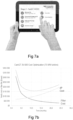
- Data representing life expectancy of the filter and associated filter costs over the estimated life time may be presented in graphical images.
- Figure 7b illustrates a graphical presentation of life cycle cost of the filter and a cost associated with continued operation of the deteriorating filter, i.e., costs relating to a reduction in output from the power plant.
- a power plant operator may provide additional operational data to the air filter control station.
- the collected data is processed. Such processing implies correcting data for flow conditions, creating historical trend lines for pressure drop, dP, based on measured data, and forecast future dP based on the historical trend lines.
- the air filter control station also converts the pressure drop value into a monetary value to visualize a decrease in production output due to pressure drop.
- the end user receives visual information on time until the filters need to be replaced due to technical reasons, i.e. pressure loss; time until filter replacement is recommended for commercial reasons; cost savings for making the filter replacement based on commercial reasons rather than technical reasons.
- An important aspect in the presentation of commercial aspects is the degradation in the performance of the industrial installation, e.g., suffered from degradation of the airflow to the combustion chamber of the combustion turbine.
- Figure 5 discloses a flow diagram of exemplary method steps performed in an air filter device.
- the air filter device is configured to obtain S51 sensor data using well known sensor technology. Such sensor data comprises sensor data generated from state of the art sensors arranged on or in the air filter arrangement. From the system perspective, the invention is not limited to a certain placement of the sensors, even though a compact, smart air filter device provides a number of benefits for the accuracy in the measured sensor data and for the ability to replace defective sensors without delay.
- the air filter device further comprises a microprocessor configured to process S52 the obtained sensor data to determine operating state information representing an operating state of the air filter arrangement where the air filter device is located.
- the air filter device transmits S53 the operating state information to a receiving remote air filter control station. The transmission of processed sensor data from the air filter sensor device to the air filter control station may at least in part be performed over a wireless communication link.
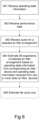
- Figure 6 discloses a flow diagram of an example method performed in an air filter control station for air filter management in an air filter management system.
- the method comprises receiving S61 operating state information from a plurality of air filter devices.
- the air filter devices may also be arranged to receive S62 performance data relevant for the industrial installation wherein the air filter arrangement is operated.
- the air filter control station receives S63 a filter condition query relevant for a selected air filter arrangement of one or more air filter devices in the air filter management system.
- the air filter control station processes the query and estimates S64 a life expectancy of the selected air filter arrangement based on operating state information received from the corresponding air filter device and on operating state information received from one or more other air filter devices.
- a life cycle cost is estimated based on the estimated life expectancy and performance data for the industrial installation of the selected air filter arrangement.
- a filter replacement cost derivable from the estimated life expectancy may be compared to the operational costs derivable from use of the air filter arrangement in the industrial installations, e.g., the costs associated with a reduced output from a combustion turbine power plant when operating using an air filter arrangement approaching the end of its life time. As previously mentioned, such reduced output may result from a reduced air inflow to support the combustion process.
- the query is received S63 over a user interface accessible to an operator of the industrial installation, e.g. a power plant operator, and/or to filter maintenance personnel or any other authorized recipient.
- the estimate for a life expectancy of the selected filter arrangement may either be performed upon receipt of data in the system, i.e., for any filter in the air filter arrangement as soon as new data is entered into the system or on receipt of a query relating to life expectancy of a given air filter arrangement.
- life expectancy for all air filter devices enlisted with the air filter control station is continuously updated as soon as new data is received in the system.
- the estimate of life expectancy of a selected air filter arrangement is preferably achieved by using metamodeling, such as the Kriging model, that allows for a design optimization in an iterative process without undue computing efforts.
- metamodeling such as the Kriging model
- the specific modelling principles for estimating the life expectancy are not part of the present invention where a life expectancy estimate may be derived from use of a plurality of modelling techniques.
- Figure 7a discloses an example of a user interface to an air filter control station, wherein at least part of the software and processing capability of the air filter control station is embodied in a tablet.
- Figure 7b discloses an example of a graphical image disclosing operator aspect, wherein a cost impact of air inlet to the combustion turbine is calculated and displayed.
- the cost impact includes increases in the fuel cost, loss of output power due to pressure loss in the filter, and filter replacement cost. While the filter replacement cost is diminishing over time, the cost trend for production loss is the opposite. Having access to accurate estimates of these costs and the expected filter life time, it is possible to calculate, in real time, the most optimal filter replacement or conditioning interval and to receive advice on monetary savings that may be gained from following a recommendation to change filter at a given point in time.
- the air filter control station may be a cloud application wherein data is collected and analyzed at regular intervals, e.g., once per day.
- Each customer receives a login and password that gives them access to filter data for some or all combustion turbines in their fleet.
- the customer is able to determine the condition of every air flow inlet to the combustion turbine power plants, the technical lifetime of the filter arrangement and the economic lifetime for the filter arrangement, i.e., the point in time when the cost of maintaining the filter in further operation surpasses the cost for exchanging the filter.
- Data from the air filter control station may also be accessible to filter replacement providers so that they are able to improve service with regard to aftermarket filter replacement sales, but also to suggest amendments to the filter configurations based on historical performance data.
- the present invention also relates to a computer program product arranged to perform the above disclosed method steps when executed in an air filter management system comprising a plurality of air filter devices and an air filter control station.
- the air filter device and the air filter management system disclosed in the description above provide the advantage of enabling access to additional data for estimating costs and benefits of a filter replacement. Furthermore, the air filter device provide access to more reliable filter data delivered to the air filter management system, thus improving the quality of the estimations even further.
Claims (15)
- System zur Luftfilterverwaltung (40), wobei das System eine Vielzahl von Luftfiltervorrichtungen (41a, b) und einen Luftfiltersteuerstand (42) umfasst, wobei jede Luftfiltervorrichtung (41a, b) an einer Luftfilteranordnung bereitgestellt ist, die in dem System in einem Luftstromeinlass beinhaltet ist, der mit einer Betriebsanlage verbindbar ist, wobei die Luftfilteranordnung mindestens ein Filtermedium, das fähig ist, Teilchenmaterial und/oder luftgetragene molekulare Kontamination (abgekürzt AMC) aus einem Luftstrom zu entfernen, der an dem Luftstromeinlass empfangen wird, wobei jede Luftfiltervorrichtung einen Satz von Sensoren umfasst, die dazu ausgelegt sind, Sensordaten zu erfassen, die einen Betriebszustand der Luftfilteranordnung, an der die Luftfiltervorrichtung bereitgestellt ist, darstellen, einen Mikroprozessor, der dazu ausgelegt ist, Betriebszustandsinformationen für die Luftfilteranordnung basierend auf den erfassten Sensordaten zu bestimmen, und eine erste Kommunikationseinheit umfasst, die dazu ausgelegt ist, die Betriebszustandsinformationen zu übertragen, wobei der Luftfiltersteuerstand (42) eine zweite Kommunikationseinheit umfasst, die dazu ausgelegt ist, Betriebszustandsinformationen von einer Vielzahl von Luftfiltervorrichtungen zu empfangen; eine Benutzerschnittstelle zum Auswählen einer Luftfilteranordnung; and eine Verarbeitungsschaltung, die dazu ausgelegt ist, eine Lebensdauererwartung der ausgewählten Luftfilteranordnung zu schätzen, dadurch gekennzeichnet, dass die geschätzte Lebensdauererwartung auf Betriebszustandsinformationen, die von einer Luftfiltervorrichtung (41a) empfangen werden, die an der ausgewählten Luftfilteranordnung bereitgestellt ist, und Betriebszustandsinformationen, die von einer oder mehreren anderen Luftfiltervorrichtungen (41b) in Echtzeit empfangen werden, die an anderen Luftfilteranordnungen bereitgestellt werden, basiert.
- System nach Anspruch 1, wobei mindestens eine von der einen oder den mehreren anderen Luftfiltervorrichtungen (41b) an einer Luftfilteranordnung in einem Luftstromeinlass zu einer anderen Betriebsanlage bereitgestellt ist.
- System nach Anspruch 1 oder 2, wobei der Satz von Sensoren eines oder mehrere von einem Durchflusssensor, einem Feuchtigkeitssensor, einem Umgebungsstaubkonzentrationssensor und einem Druckabfallsensor umfasst.
- System nach einem der Ansprüche 1-3, wobei der Luftfiltersteuerstand (42) ferner dazu ausgelegt ist, Leistungsdaten für Betriebsanlagen, die jeweiligen Luftfilteranordnungen entsprechen, zu empfangen und Lebensdauerkosten basierend auf der geschätzten Lebensdauererwartung und Leistungsdaten für die Betriebsanlage der ausgewählten Luftfilteranordnung zu schätzen.
- System nach Anspruch 4, wobei die Lebensdauerkostenschätzung auch auf Leistungsdaten basiert, die von einer oder mehreren anderen Luftfiltervorrichtungen empfangen werden, die an anderen Luftfilteranordnungen bereitgestellt sind.
- System nach Anspruch 4 oder 5, wobei jede Luftfiltervorrichtung (41a, b) ferner dazu ausgelegt ist, Leistungsdaten für die Betriebsanlage der jeweiligen Luftfilteranordnung einzuholen und die eingeholten Leistungsdaten an den Luftfiltersteuerstand zu übertragen.
- System nach Anspruch 6, wobei die Leistungsdaten über die Benutzerschnittstelle empfangen werden.
- System nach einem der vorhergehenden Ansprüche, wobei die Betriebszustandsinformationen eine Trendlinie eines Druckabfalls, dP, in der Luftfiltervorrichtung sind.
- System nach Anspruch 8, wobei die Trendlinie eines Druckabfalls, dP, in der Luftfiltervorrichtung aus einer Korrelation von Sensordaten von einem oder mehreren Filterdruckabfallsensoren und Sensordaten von mindestens einem Durchflusssensor, Umgebungsstaubkonzentrationssensor und/oder Feuchtigkeitssensor berechnet wird.
- System nach einem der vorhergehenden Ansprüche, wobei die Betriebsanlage ein Gasturbinenkraftwerk, eine turbinenbetriebene Kompressorstation oder ein turbinenbetriebener mechanischer Antrieb ist.
- System nach Anspruch 10, wobei die Leistungsdaten einen Ausstoß des Gasturbinenkraftwerks darstellen.
- Verfahren, das in einem Luftfiltersteuerstand des Systems (40) zur Luftfilterverwaltung nach einem der Ansprüche 1-11 durchgeführt wird, wobei das Verfahren Folgendes umfasst:- Empfangen (S61) von Betriebszustandsinformationen von einer Vielzahl von Luftfiltervorrichtungen, wobei jede Luftfiltervorrichtung an einer Luftfilteranordnung bereitgestellt ist,- Empfangen (S63) einer Anfrage, über eine Benutzerschnittstelle, für eine ausgewählte Luftfilteranordnung einer Luftfiltervorrichtung; und- Schätzen (S64) einer Lebensdauererwartung der ausgewählten Luftfilteranordnung basierend auf Betriebszustandsinformationen,dadurch gekennzeichnet, dass die Betriebszustandsinformationen von einer Luftfiltervorrichtung (41a), die an der ausgewählten Luftfilteranordnung bereitgestellt ist, empfangen werden und Betriebszustandsinformationen, die in Echtzeit von einer oder mehreren anderen Luftfiltervorrichtungen (41b) empfangen werden, die an anderen Luftfilteranordnungen bereitgestellt werden.
- Verfahren nach Anspruch 12, ferner umfassend:- Empfangen (S62) von Leistungsdaten für Betriebsanlagen, die jeweiligen Luftfilteranordnungen entsprechen, und- Schätzen (S65) von Lebensdauerkosten basierend auf der geschätzten Lebensdauererwartung und Leistungsdaten für die Betriebsanlage der ausgewählten Luftfilteranordnung.
- Verfahren nach Anspruch 12 oder 13, wobei die Schätzung für die Lebensdauererwartung als Reaktion auf einen Empfang der Sensordaten von einer Vielzahl von Luftfiltervorrichtungen oder als Reaktion auf den Empfang der Anfrage für eine ausgewählte Luftfilteranordnung einer Luftfiltervorrichtung erzeugt wird.
- Computerprogrammprodukt, umfassend einen Computerprogrammcode, der, wenn er in dem System nach den Ansprüchen 1-11 ausgeführt wird, dazu ausgelegt ist, das Verfahren nach einem der Ansprüche 12-14 durchzuführen.
Applications Claiming Priority (2)
| Application Number | Priority Date | Filing Date | Title |
|---|---|---|---|
| SE1650244A SE539464C2 (en) | 2016-02-24 | 2016-02-24 | System, method and computer program product for air filter management |
| PCT/SE2017/050169 WO2017146637A1 (en) | 2016-02-24 | 2017-02-22 | System, method and computer program product for air filter management |
Publications (2)
| Publication Number | Publication Date |
|---|---|
| EP3420281A1 EP3420281A1 (de) | 2019-01-02 |
| EP3420281B1 true EP3420281B1 (de) | 2023-07-19 |
Family
ID=58361059
Family Applications (1)
| Application Number | Title | Priority Date | Filing Date |
|---|---|---|---|
| EP17712256.1A Active EP3420281B1 (de) | 2016-02-24 | 2017-02-22 | System, verfahren und computerprogrammprodukt zur luftfilterverwaltung |
Country Status (9)
| Country | Link |
|---|---|
| US (1) | US10976065B2 (de) |
| EP (1) | EP3420281B1 (de) |
| CN (1) | CN108779925B (de) |
| CA (1) | CA3013201C (de) |
| ES (1) | ES2959789T3 (de) |
| MY (1) | MY194136A (de) |
| RU (1) | RU2704944C1 (de) |
| SE (1) | SE539464C2 (de) |
| WO (1) | WO2017146637A1 (de) |
Families Citing this family (41)
| Publication number | Priority date | Publication date | Assignee | Title |
|---|---|---|---|---|
| EP3702685A1 (de) | 2012-08-28 | 2020-09-02 | Delos Living LLC | Klimaregelungssystem und verfahren zum betrieb solch eines systems |
| WO2015130786A1 (en) | 2014-02-28 | 2015-09-03 | Delos Living Llc | Systems, methods and articles for enhancing wellness associated with habitable environments |
| CN112973258B (zh) * | 2016-04-08 | 2022-07-26 | 康明斯滤清系统知识产权公司 | 经由远程信息处理输出过滤器监测系统信息的系统和方法 |
| JP6998119B2 (ja) * | 2017-03-29 | 2022-01-18 | 三菱重工業株式会社 | プラント評価システム、プラント評価方法及びプログラム |
| US10816234B2 (en) | 2017-04-14 | 2020-10-27 | Johnson Controls Technology Company | Systems and methods for HVAC filter replacement type recommendation |
| US11668481B2 (en) | 2017-08-30 | 2023-06-06 | Delos Living Llc | Systems, methods and articles for assessing and/or improving health and well-being |
| SE541077C2 (en) * | 2017-09-05 | 2019-03-26 | Husqvarna Ab | Separator, separator system and methods of their operation |
| CN107461894A (zh) * | 2017-09-15 | 2017-12-12 | 深圳市晓风建筑环境科技有限公司 | 一种空气净化器及其滤网监控方法和装置、以及存储介质 |
| US10767878B2 (en) | 2017-11-21 | 2020-09-08 | Emerson Climate Technologies, Inc. | Humidifier control systems and methods |
| US11065568B2 (en) | 2018-01-19 | 2021-07-20 | Mann+Hummel Gmbh | Smart filter module analysis system and associated methods |
| US11486593B2 (en) | 2018-04-20 | 2022-11-01 | Emerson Climate Technologies, Inc. | Systems and methods with variable mitigation thresholds |
| US11371726B2 (en) | 2018-04-20 | 2022-06-28 | Emerson Climate Technologies, Inc. | Particulate-matter-size-based fan control system |
| WO2019204790A1 (en) | 2018-04-20 | 2019-10-24 | Emerson Climate Technologies, Inc. | Systems and methods with variable mitigation thresholds |
| US20210236979A1 (en) * | 2018-04-20 | 2021-08-05 | Emerson Climate Technologies, Inc. | Particulate-matter-size-based fan control system |
| US11226128B2 (en) | 2018-04-20 | 2022-01-18 | Emerson Climate Technologies, Inc. | Indoor air quality and occupant monitoring systems and methods |
| WO2019204792A1 (en) | 2018-04-20 | 2019-10-24 | Emerson Climate Technologies, Inc. | Coordinated control of standalone and building indoor air quality devices and systems |
| GB201808579D0 (en) * | 2018-05-24 | 2018-07-11 | Environmental Dust Monitor Systems Ltd | Remote filter monitoring |
| US11649977B2 (en) | 2018-09-14 | 2023-05-16 | Delos Living Llc | Systems and methods for air remediation |
| EP3628388A1 (de) * | 2018-09-26 | 2020-04-01 | Valeo Systemes Thermiques | Computerimplementiertes verfahren und system zur schätzung einer filterverstopfung |
| US11960261B2 (en) | 2019-07-12 | 2024-04-16 | Johnson Controls Tyco IP Holdings LLP | HVAC system with sustainability and emissions controls |
| CN113242755A (zh) | 2018-10-25 | 2021-08-10 | 唐纳森公司 | 用于空气过滤系统的监测装置 |
| US10828986B2 (en) * | 2019-01-07 | 2020-11-10 | Mann+Hummel Gmbh | Cabin air filter element monitoring and analysis system and associated methods |
| US11761660B2 (en) | 2019-01-30 | 2023-09-19 | Johnson Controls Tyco IP Holdings LLP | Building control system with feedback and feedforward total energy flow compensation |
| WO2020176503A1 (en) | 2019-02-26 | 2020-09-03 | Delos Living Llc | Method and apparatus for lighting in an office environment |
| US20200289968A1 (en) * | 2019-03-12 | 2020-09-17 | Bissell Inc. | Air purifier in a furniture article |
| US11898898B2 (en) | 2019-03-25 | 2024-02-13 | Delos Living Llc | Systems and methods for acoustic monitoring |
| EP3973230B1 (de) | 2019-05-20 | 2023-09-06 | Belimo Holding AG | Verfahren und computersystem zur überwachung und steuerung eines hlk-systems |
| US11274842B2 (en) | 2019-07-12 | 2022-03-15 | Johnson Controls Tyco IP Holdings LLP | Systems and methods for optimizing ventilation, filtration, and conditioning schemes for buildings |
| US11714393B2 (en) | 2019-07-12 | 2023-08-01 | Johnson Controls Tyco IP Holdings LLP | Building control system with load curtailment optimization |
| WO2021011464A1 (en) * | 2019-07-12 | 2021-01-21 | Johnson Controls Technology Company | Heat mapping, air quality control, and disinfection system |
| JP2021110475A (ja) * | 2020-01-07 | 2021-08-02 | ダイキン工業株式会社 | 有用情報提供システム |
| WO2021149135A1 (ja) * | 2020-01-21 | 2021-07-29 | 株式会社テクノミライ | デジタル・クーリングコントロール・システム |
| EP4142914A1 (de) * | 2020-04-30 | 2023-03-08 | Integrated Viral Protection Solutions, LLC | Mobile reinigungsvorrichtung mit einem beheizten filter zum abtöten biologischer spezies, einschliesslich covid-19 |
| US11235272B2 (en) * | 2020-05-23 | 2022-02-01 | Sid Chaudhuri | IoT enabled smart filter device |
| CN115715226A (zh) * | 2020-06-11 | 2023-02-24 | 胡斯华纳有限公司 | 用于工业除尘器的过滤设备 |
| SE545877C2 (en) * | 2020-06-11 | 2024-02-27 | Husqvarna Ab | Filter arrangements for industrial dust extractors |
| CN111536633A (zh) * | 2020-06-12 | 2020-08-14 | 深圳市中建南方环境股份有限公司 | 一种具备高效过滤机组的新型空气净化系统、方法和装置 |
| EP3944885A1 (de) * | 2020-07-30 | 2022-02-02 | Siemens Energy Global GmbH & Co. KG | Motorfiltermanagement mit kontinuierlicher strömung |
| US11446600B2 (en) | 2020-12-10 | 2022-09-20 | Hourani Ip, Llc | Detoxification device having heated filter for killing pathogens |
| JP2024517163A (ja) * | 2021-04-27 | 2024-04-19 | ヘルスウェイ ホーム プロダクツ カンパニー インコーポレイテッド | 除菌空気濾過システム構成 |
| CN115430224A (zh) * | 2022-09-28 | 2022-12-06 | 圣晖系统集成集团股份有限公司 | 一种过滤结构及计算化学滤网更换时间的方法 |
Citations (17)
| Publication number | Priority date | Publication date | Assignee | Title |
|---|---|---|---|---|
| US6009404A (en) | 1995-02-10 | 1999-12-28 | Tepcon Engineering Gesellschaft Gmbh | Method and device for cost-orientated operation of a conditioning device particularly a filter |
| US6423118B1 (en) | 2000-09-05 | 2002-07-23 | General Electric Company | Methods and systems for controlling air filtration systems |
| US7261762B2 (en) | 2004-05-06 | 2007-08-28 | Carrier Corporation | Technique for detecting and predicting air filter condition |
| EP2233993A1 (de) | 2009-03-25 | 2010-09-29 | Oliver Frieters | Steuerungs-Baukasten |
| US20110036145A1 (en) | 2009-08-14 | 2011-02-17 | Dobbyn Gregory J | Ductless fume hood gas monitoring and detection system |
| US20130197829A1 (en) | 2012-01-31 | 2013-08-01 | William Sherman, III | Filter clog sensing system and method for compensating in response to blower speed changes |
| US20140208942A1 (en) | 2013-01-28 | 2014-07-31 | General Electric Company | Method, Apparatus, And System For Air Filter Cleaning |
| WO2015042960A1 (en) | 2013-09-30 | 2015-04-02 | Schneider Electric It Corporation | Method and system for detecting dust accumulation in a hvac filtering system |
| WO2015073698A1 (en) * | 2012-11-13 | 2015-05-21 | Beier Michael B | Filtration monitoring system |
| WO2015073669A1 (en) | 2013-11-18 | 2015-05-21 | Bha Altair, Llc | Systems and methods for managing turbine intake filters |
| SE537506C2 (sv) | 2011-12-19 | 2015-05-26 | Dinair Ab | Förfarande för optimering av brukstiden för filter mellan filterbyten i ett ventilationssystem |
| US20150241318A1 (en) | 2013-03-19 | 2015-08-27 | International Business Machines Corporation | Filter replacement lifetime prediction |
| US20150260424A1 (en) | 2010-11-19 | 2015-09-17 | Google Inc. | Hvac filter monitoring |
| US20150285517A1 (en) | 2014-04-04 | 2015-10-08 | Magni-Power Company | System for determining force imparted by a filter in a variable force environment and related methods of use |
| US20150283491A1 (en) | 2012-04-20 | 2015-10-08 | International Business Machines Corporation | Filter systems |
| US20150306533A1 (en) | 2014-04-25 | 2015-10-29 | Fellowes, Inc. | Air Purifier with Intelligent Sensors and Intellectual Airflow |
| WO2015164237A1 (en) | 2014-04-24 | 2015-10-29 | 3M Innovative Properties Company | System and method for maintenance and monitoring of filtration systems |
Family Cites Families (5)
| Publication number | Priority date | Publication date | Assignee | Title |
|---|---|---|---|---|
| DK1674144T3 (da) * | 2004-12-23 | 2007-11-05 | Gore W L & Ass Gmbh | Luftfilter for en turbine |
| TWI515035B (zh) * | 2009-03-02 | 2016-01-01 | 科邁實業有限公司 | 可再生皺褶式過濾器媒介 |
| FR2973718B1 (fr) * | 2011-04-06 | 2015-11-06 | Degremont | Dispositif et procede pour tester des modules de filtration membranaires, en particulier des modules d'ultrafiltration, de microfiltration ou d'osmose inverse |
| CN103019161A (zh) * | 2011-09-20 | 2013-04-03 | 朗德华信(北京)自控技术有限公司 | 基于云计算的空气处理设备管理控制系统及方法 |
| CN104524896B (zh) * | 2014-12-29 | 2017-07-04 | 东莞市宇洁新材料有限公司 | 一种可检测颗粒物过滤器寿命的室内空气净化装置及其检测方法 |
-
2016
- 2016-02-24 SE SE1650244A patent/SE539464C2/en unknown
-
2017
- 2017-02-22 CA CA3013201A patent/CA3013201C/en active Active
- 2017-02-22 MY MYPI2018702931A patent/MY194136A/en unknown
- 2017-02-22 RU RU2018133452A patent/RU2704944C1/ru active
- 2017-02-22 EP EP17712256.1A patent/EP3420281B1/de active Active
- 2017-02-22 WO PCT/SE2017/050169 patent/WO2017146637A1/en active Application Filing
- 2017-02-22 ES ES17712256T patent/ES2959789T3/es active Active
- 2017-02-22 CN CN201780013608.XA patent/CN108779925B/zh active Active
- 2017-02-22 US US16/075,046 patent/US10976065B2/en active Active
Patent Citations (17)
| Publication number | Priority date | Publication date | Assignee | Title |
|---|---|---|---|---|
| US6009404A (en) | 1995-02-10 | 1999-12-28 | Tepcon Engineering Gesellschaft Gmbh | Method and device for cost-orientated operation of a conditioning device particularly a filter |
| US6423118B1 (en) | 2000-09-05 | 2002-07-23 | General Electric Company | Methods and systems for controlling air filtration systems |
| US7261762B2 (en) | 2004-05-06 | 2007-08-28 | Carrier Corporation | Technique for detecting and predicting air filter condition |
| EP2233993A1 (de) | 2009-03-25 | 2010-09-29 | Oliver Frieters | Steuerungs-Baukasten |
| US20110036145A1 (en) | 2009-08-14 | 2011-02-17 | Dobbyn Gregory J | Ductless fume hood gas monitoring and detection system |
| US20150260424A1 (en) | 2010-11-19 | 2015-09-17 | Google Inc. | Hvac filter monitoring |
| SE537506C2 (sv) | 2011-12-19 | 2015-05-26 | Dinair Ab | Förfarande för optimering av brukstiden för filter mellan filterbyten i ett ventilationssystem |
| US20130197829A1 (en) | 2012-01-31 | 2013-08-01 | William Sherman, III | Filter clog sensing system and method for compensating in response to blower speed changes |
| US20150283491A1 (en) | 2012-04-20 | 2015-10-08 | International Business Machines Corporation | Filter systems |
| WO2015073698A1 (en) * | 2012-11-13 | 2015-05-21 | Beier Michael B | Filtration monitoring system |
| US20140208942A1 (en) | 2013-01-28 | 2014-07-31 | General Electric Company | Method, Apparatus, And System For Air Filter Cleaning |
| US20150241318A1 (en) | 2013-03-19 | 2015-08-27 | International Business Machines Corporation | Filter replacement lifetime prediction |
| WO2015042960A1 (en) | 2013-09-30 | 2015-04-02 | Schneider Electric It Corporation | Method and system for detecting dust accumulation in a hvac filtering system |
| WO2015073669A1 (en) | 2013-11-18 | 2015-05-21 | Bha Altair, Llc | Systems and methods for managing turbine intake filters |
| US20150285517A1 (en) | 2014-04-04 | 2015-10-08 | Magni-Power Company | System for determining force imparted by a filter in a variable force environment and related methods of use |
| WO2015164237A1 (en) | 2014-04-24 | 2015-10-29 | 3M Innovative Properties Company | System and method for maintenance and monitoring of filtration systems |
| US20150306533A1 (en) | 2014-04-25 | 2015-10-29 | Fellowes, Inc. | Air Purifier with Intelligent Sensors and Intellectual Airflow |
Also Published As
| Publication number | Publication date |
|---|---|
| BR112018017295A8 (pt) | 2022-06-28 |
| CA3013201A1 (en) | 2017-08-31 |
| RU2704944C1 (ru) | 2019-10-31 |
| SE1650244A1 (en) | 2017-08-25 |
| ES2959789T3 (es) | 2024-02-28 |
| SE539464C2 (en) | 2017-09-26 |
| CN108779925B (zh) | 2021-05-07 |
| WO2017146637A1 (en) | 2017-08-31 |
| US20190041079A1 (en) | 2019-02-07 |
| US10976065B2 (en) | 2021-04-13 |
| CN108779925A (zh) | 2018-11-09 |
| EP3420281A1 (de) | 2019-01-02 |
| BR112018017295A2 (pt) | 2019-01-02 |
| CA3013201C (en) | 2021-01-26 |
| MY194136A (en) | 2022-11-14 |
Similar Documents
| Publication | Publication Date | Title |
|---|---|---|
| EP3420281B1 (de) | System, verfahren und computerprogrammprodukt zur luftfilterverwaltung | |
| WO2017146633A1 (en) | Air filter arrangement, device and system | |
| US20210207833A1 (en) | Device and method for monitoring hvac air filter | |
| US10724927B2 (en) | Filter replacement lifetime prediction | |
| CN208057242U (zh) | 用于压缩机的基于条件的监测的涡轮系统 | |
| CN107816386A (zh) | 涡轮系统、计算机实现的监测方法以及计算机可读介质 | |
| US20190195525A1 (en) | Method and apparatus for operating heating and cooling equipment via a network | |
| CN108361916B (zh) | 智能实时风道滤网堵塞程度判定系统及方法 | |
| WO2018228648A1 (en) | Independent monitoring system for a wind turbine | |
| KR102376355B1 (ko) | 필터의 교체주기 간 수명의 최적화 방법 및 환기 시스템의 모니터링 시스템 | |
| KR20140130540A (ko) | 설비들의 그룹의 조건 모니터링을 위한 방법 및 시스템 | |
| JP2003162324A (ja) | ビル内のユーティリティの異常使用を検出するインテリジェント・データ分析法 | |
| CN109612029B (zh) | 效能预测方法 | |
| US10207213B2 (en) | Turbomachinery filter change forecaster | |
| KR20150054974A (ko) | 기술 시스템, 특히 전기 에너지-발생 설비의 동작의 컴퓨터-보조 모니터링을 위한 방법 | |
| US20210060474A1 (en) | Method for predicting the service life of a filter | |
| CN114341896A (zh) | 用于检测过滤器脏污程度的系统和方法 | |
| CN113790102B (zh) | 一种燃气轮机进气过滤器的智能运维系统 | |
| BR112018017295B1 (pt) | Sistema e método para gerenciamento de filtro de ar, e, meio de armazenamento em memória | |
| CN117073136B (zh) | 一种基于安全值校验的过滤网清洁提醒方法及系统 | |
| CN116805194A (zh) | 基于云平台的大数据处理分析系统 | |
| CN116709058A (zh) | 一种在线用水模式识别设备 | |
| CN115902483A (zh) | 一种电力系统中用电计量监测预警装置 |
Legal Events
| Date | Code | Title | Description |
|---|---|---|---|
| STAA | Information on the status of an ep patent application or granted ep patent |
Free format text: STATUS: UNKNOWN |
|
| STAA | Information on the status of an ep patent application or granted ep patent |
Free format text: STATUS: THE INTERNATIONAL PUBLICATION HAS BEEN MADE |
|
| PUAI | Public reference made under article 153(3) epc to a published international application that has entered the european phase |
Free format text: ORIGINAL CODE: 0009012 |
|
| STAA | Information on the status of an ep patent application or granted ep patent |
Free format text: STATUS: REQUEST FOR EXAMINATION WAS MADE |
|
| 17P | Request for examination filed |
Effective date: 20180828 |
|
| AK | Designated contracting states |
Kind code of ref document: A1 Designated state(s): AL AT BE BG CH CY CZ DE DK EE ES FI FR GB GR HR HU IE IS IT LI LT LU LV MC MK MT NL NO PL PT RO RS SE SI SK SM TR |
|
| AX | Request for extension of the european patent |
Extension state: BA ME |
|
| DAV | Request for validation of the european patent (deleted) | ||
| DAX | Request for extension of the european patent (deleted) | ||
| STAA | Information on the status of an ep patent application or granted ep patent |
Free format text: STATUS: EXAMINATION IS IN PROGRESS |
|
| STAA | Information on the status of an ep patent application or granted ep patent |
Free format text: STATUS: EXAMINATION IS IN PROGRESS |
|
| 17Q | First examination report despatched |
Effective date: 20201007 |
|
| STAA | Information on the status of an ep patent application or granted ep patent |
Free format text: STATUS: EXAMINATION IS IN PROGRESS |
|
| RAP1 | Party data changed (applicant data changed or rights of an application transferred) |
Owner name: CAMFIL AB |
|
| RIC1 | Information provided on ipc code assigned before grant |
Ipc: F24F 8/10 20210101ALI20221215BHEP Ipc: F24F 110/50 20180101ALI20221215BHEP Ipc: F24F 11/63 20180101ALI20221215BHEP Ipc: F24F 11/39 20180101ALI20221215BHEP Ipc: F24F 11/30 20180101ALI20221215BHEP Ipc: B01D 46/00 20060101ALI20221215BHEP Ipc: F24F 3/16 20060101AFI20221215BHEP |
|
| GRAP | Despatch of communication of intention to grant a patent |
Free format text: ORIGINAL CODE: EPIDOSNIGR1 |
|
| STAA | Information on the status of an ep patent application or granted ep patent |
Free format text: STATUS: GRANT OF PATENT IS INTENDED |
|
| INTG | Intention to grant announced |
Effective date: 20230220 |
|
| GRAS | Grant fee paid |
Free format text: ORIGINAL CODE: EPIDOSNIGR3 |
|
| GRAA | (expected) grant |
Free format text: ORIGINAL CODE: 0009210 |
|
| STAA | Information on the status of an ep patent application or granted ep patent |
Free format text: STATUS: THE PATENT HAS BEEN GRANTED |
|
| AK | Designated contracting states |
Kind code of ref document: B1 Designated state(s): AL AT BE BG CH CY CZ DE DK EE ES FI FR GB GR HR HU IE IS IT LI LT LU LV MC MK MT NL NO PL PT RO RS SE SI SK SM TR |
|
| P01 | Opt-out of the competence of the unified patent court (upc) registered |
Effective date: 20230613 |
|
| REG | Reference to a national code |
Ref country code: GB Ref legal event code: FG4D |
|
| REG | Reference to a national code |
Ref country code: CH Ref legal event code: EP |
|
| REG | Reference to a national code |
Ref country code: DE Ref legal event code: R096 Ref document number: 602017071440 Country of ref document: DE |
|
| REG | Reference to a national code |
Ref country code: IE Ref legal event code: FG4D |
|
| REG | Reference to a national code |
Ref country code: NL Ref legal event code: FP |
|
| REG | Reference to a national code |
Ref country code: LT Ref legal event code: MG9D |
|
| REG | Reference to a national code |
Ref country code: AT Ref legal event code: MK05 Ref document number: 1589819 Country of ref document: AT Kind code of ref document: T Effective date: 20230719 |
|
| PG25 | Lapsed in a contracting state [announced via postgrant information from national office to epo] |
Ref country code: GR Free format text: LAPSE BECAUSE OF FAILURE TO SUBMIT A TRANSLATION OF THE DESCRIPTION OR TO PAY THE FEE WITHIN THE PRESCRIBED TIME-LIMIT Effective date: 20231020 |
|
| PG25 | Lapsed in a contracting state [announced via postgrant information from national office to epo] |
Ref country code: IS Free format text: LAPSE BECAUSE OF FAILURE TO SUBMIT A TRANSLATION OF THE DESCRIPTION OR TO PAY THE FEE WITHIN THE PRESCRIBED TIME-LIMIT Effective date: 20231119 |
|
| PG25 | Lapsed in a contracting state [announced via postgrant information from national office to epo] |
Ref country code: SE Free format text: LAPSE BECAUSE OF FAILURE TO SUBMIT A TRANSLATION OF THE DESCRIPTION OR TO PAY THE FEE WITHIN THE PRESCRIBED TIME-LIMIT Effective date: 20230719 Ref country code: RS Free format text: LAPSE BECAUSE OF FAILURE TO SUBMIT A TRANSLATION OF THE DESCRIPTION OR TO PAY THE FEE WITHIN THE PRESCRIBED TIME-LIMIT Effective date: 20230719 Ref country code: PT Free format text: LAPSE BECAUSE OF FAILURE TO SUBMIT A TRANSLATION OF THE DESCRIPTION OR TO PAY THE FEE WITHIN THE PRESCRIBED TIME-LIMIT Effective date: 20231120 Ref country code: NO Free format text: LAPSE BECAUSE OF FAILURE TO SUBMIT A TRANSLATION OF THE DESCRIPTION OR TO PAY THE FEE WITHIN THE PRESCRIBED TIME-LIMIT Effective date: 20231019 Ref country code: LV Free format text: LAPSE BECAUSE OF FAILURE TO SUBMIT A TRANSLATION OF THE DESCRIPTION OR TO PAY THE FEE WITHIN THE PRESCRIBED TIME-LIMIT Effective date: 20230719 Ref country code: LT Free format text: LAPSE BECAUSE OF FAILURE TO SUBMIT A TRANSLATION OF THE DESCRIPTION OR TO PAY THE FEE WITHIN THE PRESCRIBED TIME-LIMIT Effective date: 20230719 Ref country code: IS Free format text: LAPSE BECAUSE OF FAILURE TO SUBMIT A TRANSLATION OF THE DESCRIPTION OR TO PAY THE FEE WITHIN THE PRESCRIBED TIME-LIMIT Effective date: 20231119 Ref country code: HR Free format text: LAPSE BECAUSE OF FAILURE TO SUBMIT A TRANSLATION OF THE DESCRIPTION OR TO PAY THE FEE WITHIN THE PRESCRIBED TIME-LIMIT Effective date: 20230719 Ref country code: GR Free format text: LAPSE BECAUSE OF FAILURE TO SUBMIT A TRANSLATION OF THE DESCRIPTION OR TO PAY THE FEE WITHIN THE PRESCRIBED TIME-LIMIT Effective date: 20231020 Ref country code: FI Free format text: LAPSE BECAUSE OF FAILURE TO SUBMIT A TRANSLATION OF THE DESCRIPTION OR TO PAY THE FEE WITHIN THE PRESCRIBED TIME-LIMIT Effective date: 20230719 Ref country code: AT Free format text: LAPSE BECAUSE OF FAILURE TO SUBMIT A TRANSLATION OF THE DESCRIPTION OR TO PAY THE FEE WITHIN THE PRESCRIBED TIME-LIMIT Effective date: 20230719 |
|
| REG | Reference to a national code |
Ref country code: ES Ref legal event code: FG2A Ref document number: 2959789 Country of ref document: ES Kind code of ref document: T3 Effective date: 20240228 |
|
| PG25 | Lapsed in a contracting state [announced via postgrant information from national office to epo] |
Ref country code: PL Free format text: LAPSE BECAUSE OF FAILURE TO SUBMIT A TRANSLATION OF THE DESCRIPTION OR TO PAY THE FEE WITHIN THE PRESCRIBED TIME-LIMIT Effective date: 20230719 |
|
| PGFP | Annual fee paid to national office [announced via postgrant information from national office to epo] |
Ref country code: IE Payment date: 20240220 Year of fee payment: 8 Ref country code: NL Payment date: 20240219 Year of fee payment: 8 Ref country code: ES Payment date: 20240326 Year of fee payment: 8 |
|
| PLBI | Opposition filed |
Free format text: ORIGINAL CODE: 0009260 |
|
| PG25 | Lapsed in a contracting state [announced via postgrant information from national office to epo] |
Ref country code: SM Free format text: LAPSE BECAUSE OF FAILURE TO SUBMIT A TRANSLATION OF THE DESCRIPTION OR TO PAY THE FEE WITHIN THE PRESCRIBED TIME-LIMIT Effective date: 20230719 Ref country code: RO Free format text: LAPSE BECAUSE OF FAILURE TO SUBMIT A TRANSLATION OF THE DESCRIPTION OR TO PAY THE FEE WITHIN THE PRESCRIBED TIME-LIMIT Effective date: 20230719 Ref country code: EE Free format text: LAPSE BECAUSE OF FAILURE TO SUBMIT A TRANSLATION OF THE DESCRIPTION OR TO PAY THE FEE WITHIN THE PRESCRIBED TIME-LIMIT Effective date: 20230719 Ref country code: DK Free format text: LAPSE BECAUSE OF FAILURE TO SUBMIT A TRANSLATION OF THE DESCRIPTION OR TO PAY THE FEE WITHIN THE PRESCRIBED TIME-LIMIT Effective date: 20230719 Ref country code: CZ Free format text: LAPSE BECAUSE OF FAILURE TO SUBMIT A TRANSLATION OF THE DESCRIPTION OR TO PAY THE FEE WITHIN THE PRESCRIBED TIME-LIMIT Effective date: 20230719 Ref country code: SK Free format text: LAPSE BECAUSE OF FAILURE TO SUBMIT A TRANSLATION OF THE DESCRIPTION OR TO PAY THE FEE WITHIN THE PRESCRIBED TIME-LIMIT Effective date: 20230719 |
|
| PGFP | Annual fee paid to national office [announced via postgrant information from national office to epo] |
Ref country code: DE Payment date: 20240219 Year of fee payment: 8 Ref country code: GB Payment date: 20240219 Year of fee payment: 8 |
|
| PLAX | Notice of opposition and request to file observation + time limit sent |
Free format text: ORIGINAL CODE: EPIDOSNOBS2 |