EP3420188B1 - Bestimmung der eigenschaften von ausfleckungsflüssigkeiten - Google Patents
Bestimmung der eigenschaften von ausfleckungsflüssigkeiten Download PDFInfo
- Publication number
- EP3420188B1 EP3420188B1 EP17704947.5A EP17704947A EP3420188B1 EP 3420188 B1 EP3420188 B1 EP 3420188B1 EP 17704947 A EP17704947 A EP 17704947A EP 3420188 B1 EP3420188 B1 EP 3420188B1
- Authority
- EP
- European Patent Office
- Prior art keywords
- mudcake
- mudcake sample
- spotting fluid
- test
- sample
- Prior art date
- Legal status (The legal status is an assumption and is not a legal conclusion. Google has not performed a legal analysis and makes no representation as to the accuracy of the status listed.)
- Active
Links
Images







Classifications
-
- E—FIXED CONSTRUCTIONS
- E21—EARTH OR ROCK DRILLING; MINING
- E21B—EARTH OR ROCK DRILLING; OBTAINING OIL, GAS, WATER, SOLUBLE OR MELTABLE MATERIALS OR A SLURRY OF MINERALS FROM WELLS
- E21B49/00—Testing the nature of borehole walls; Formation testing; Methods or apparatus for obtaining samples of soil or well fluids, specially adapted to earth drilling or wells
- E21B49/003—Testing the nature of borehole walls; Formation testing; Methods or apparatus for obtaining samples of soil or well fluids, specially adapted to earth drilling or wells by analysing drilling variables or conditions
-
- E—FIXED CONSTRUCTIONS
- E21—EARTH OR ROCK DRILLING; MINING
- E21B—EARTH OR ROCK DRILLING; OBTAINING OIL, GAS, WATER, SOLUBLE OR MELTABLE MATERIALS OR A SLURRY OF MINERALS FROM WELLS
- E21B31/00—Fishing for or freeing objects in boreholes or wells
- E21B31/035—Fishing for or freeing objects in boreholes or wells controlling differential pipe sticking
-
- E—FIXED CONSTRUCTIONS
- E21—EARTH OR ROCK DRILLING; MINING
- E21B—EARTH OR ROCK DRILLING; OBTAINING OIL, GAS, WATER, SOLUBLE OR MELTABLE MATERIALS OR A SLURRY OF MINERALS FROM WELLS
- E21B49/00—Testing the nature of borehole walls; Formation testing; Methods or apparatus for obtaining samples of soil or well fluids, specially adapted to earth drilling or wells
- E21B49/005—Testing the nature of borehole walls or the formation by using drilling mud or cutting data
-
- G—PHYSICS
- G01—MEASURING; TESTING
- G01L—MEASURING FORCE, STRESS, TORQUE, WORK, MECHANICAL POWER, MECHANICAL EFFICIENCY, OR FLUID PRESSURE
- G01L25/00—Testing or calibrating of apparatus for measuring force, torque, work, mechanical power, or mechanical efficiency
-
- G—PHYSICS
- G01—MEASURING; TESTING
- G01N—INVESTIGATING OR ANALYSING MATERIALS BY DETERMINING THEIR CHEMICAL OR PHYSICAL PROPERTIES
- G01N11/00—Investigating flow properties of materials, e.g. viscosity, plasticity; Analysing materials by determining flow properties
- G01N11/10—Investigating flow properties of materials, e.g. viscosity, plasticity; Analysing materials by determining flow properties by moving a body within the material
-
- G—PHYSICS
- G01—MEASURING; TESTING
- G01N—INVESTIGATING OR ANALYSING MATERIALS BY DETERMINING THEIR CHEMICAL OR PHYSICAL PROPERTIES
- G01N19/00—Investigating materials by mechanical methods
- G01N19/04—Measuring adhesive force between materials, e.g. of sealing tape, of coating
Definitions
- This disclosure relates to methods and systems for determining one or more properties of a spotting fluid for use in a wellbore.
- Tubular members such as drill pipe or otherwise
- Pipe sticking can be a problem in the drilling and formation of wellbores that can cause non-productive drilling time. Pipe sticking can also trigger other drilling problems and sometimes may lead to a costly fishing operation to retrieve the stuck tubular, abandonment of the operation, or side tracking of the wellbore.
- conventional techniques have been developed to predict pipe sticking in advance, for example, by evaluating properties related to an interface in a drilling mud and the tubular in the wellbore.
- the drilling mud when in contact with a rock formation of the wellbore, may develop a mudcake (for example, drilling fluid that attaches to the wellbore under pressure).
- Conventional techniques that are used to determine sticking or adherence properties of a mudcake to a rigid tubular (for example, a metallic drilling string) are often not reliable or accurate.
- a fluid for example, a liquid
- the fluid typically called a "spotting fluid”
- spotting fluid may help unstick the pipe from the wellbore.
- conventional techniques that are used to determine sticking or adherence properties of a spotting fluid for freeing a rigid tubular (for example, a metallic drilling string) are often not reliable or accurate.
- US 4,829,816 describes an apparatus and a method for testing the performance of spotting fluids used for freeing drill pipe stuck to drilling mud filter cake in a borehole.
- WO 2016/144700 A1 describes techniques for determining mudcake properties.
- a method includes positioning a member of a test apparatus into a prepared mudcake sample at a specified depth of the mudcake sample, the mudcake sample associated with a drilling fluid and including a specified thickness; pressurizing the spotting fluid in the feeder tank with a pressurized gas stored in a gas tank in fluid communication with the feeder tank; circulating a pressurized flow of the spotting fluid from the feeder tank to a test cell of the apparatus to contact the prepared mudcake sample in the test cell of the test apparatus; soaking the prepared mudcake sample in the spotting fluid for a specified time duration; subsequent to the specified time duration, detecting, with the test apparatus, a force exerted on the member relative to a displacement distance of the member from the specified depth in the mudcake sample during removal of the member from the mudcake
- An aspect combinable with the general implementation further includes collecting an overflow of the spotting fluid that flows from the test cell.
- Another aspect combinable with any of the previous aspects further includes regulating a pressure of the pressurized gas circulating from the gas tank to the feeder tank.
- Another aspect combinable with any of the previous aspects further includes initiating removal of the member from the mudcake sample by the force exerted on the member by the test apparatus.
- the specified thickness is 10 mm and the specified depth is 5 mm.
- Another aspect combinable with any of the previous aspects further includes removing the member from the mudcake sample by the force exerted on the member by the test apparatus.
- removing the member from the mudcake sample by the force exerted on the member by the test apparatus includes removing the member from the mudcake sample at a constant removal rate.
- Another aspect combinable with any of the previous aspects further includes maintaining, for a specified time period, the member in the mudcake sample prior to circulating the spotting fluid.
- the specified time period includes 2 minutes.
- Another aspect combinable with any of the previous aspects further includes determining at least one of the one or more properties based, at least in part, on the graphical recording of the force exerted on the member relative to the displacement distance.
- Another aspect combinable with any of the previous aspects further includes performing an action based at least in part on the one or more of the determined properties.
- the action includes at least one of selecting a drilling fluid to use in a drilling operation; selecting a particular spotting fluid to use in a stuck-pipe removal operation; or determining an ease of recovery of a tubular member that is stuck in a wellbore.
- a spotting fluid testing system in another general implementation, includes a test apparatus, a feeder tank, a gas tank, and a control system communicably coupled to the test apparatus.
- the test apparatus includes mudcake holder configured to restrain a mudcake sample in a stationary position; a load cell; and a testing member coupled to the load cell.
- the feeder tank positioned to circulate the flow of the spotting fluid from the feeder tank to the test cell.
- the gas tank that stores a pressurized gas, the gas tank being fluidly coupled with the feeder tank.
- the control system is configured to perform operations including: controlling the load cell to position the member into the mudcake sample at a specified depth of the mudcake sample; controlling one or more valves to circulate the pressurized gas to the feeder tank to generate a pressurized flow of the spotting fluid from the feeder tank to the test cell; controlling one or more valves of the test apparatus to circulate a flow of a spotting fluid to contact and soak the mudcake sample in a test container of the test apparatus; subsequent to a specified soaking time duration, controlling the load cell to initiate removal of the member from the mudcake sample by a force exerted on the member by the load cell; detecting, with the test apparatus, a force exerted on the member relative to a displacement distance of the member from the specified depth in the mudcake sample during removal of the member from the mudcake sample; recording, with the test apparatus, the detected force relative to the displacement distance; and determining one or more properties of the mudcake sample based on the recorded force relative to the displacement distance.
- An aspect combinable with the general implementation further includes a collection tank fluidly coupled to the test cell.
- control system is further configured to perform operations including controlling one or more valves of the test apparatus to circulate an overflow of the spotting fluid from the test cell to the collection tank.
- control system is further configured to perform operations including controlling a pressure regulator of the gas tank to adjust a pressure of the pressurized gas circulating from the gas tank to the feeder tank.
- control system is further configured to perform operations including initiating removal of the member from the mudcake sample by the force exerted on the member by the test apparatus.
- the specified thickness is 10 mm and the specified depth is 5 mm.
- control system is further configured to perform operations including removing the member from the mudcake sample by the force exerted on the member by the test apparatus.
- removing the member from the mudcake sample by the force exerted on the member by the test apparatus includes removing the member from the mudcake sample at a constant removal rate.
- the member includes a spherical member.
- one or more properties of the mudcake sample include a sticking bond modulus (SBM) and an ultimate sticking bond strength (USBS).
- SBM sticking bond modulus
- USBS ultimate sticking bond strength
- control system is further configured to perform operations including determining at least one of the one or more properties based, at least in part, on the graphical recording of the force exerted on the member relative to the displacement distance.
- control system is further configured to perform operations including recommending an action based at least in part on the one or more of the determined properties.
- the action includes at least one of: selecting a drilling fluid to use in a drilling operation; selecting a particular spotting fluid to use in a stuck-pipe removal operation; or determining an ease of recovery of a tubular member that is stuck in a wellbore.
- Implementations of methods and systems for determining one or more properties associated with a spotting fluid for reducing an adherence or sticking of a mudcake to a wellbore tubular member may include one or more of the following features.
- such methods and systems may provide results to drilling engineers that provide guidance in selecting a spotting fluid or spotting fluid composition to use to recover a tubular member stuck in a wellbore.
- methods and systems according to the present disclosure may provide a mudcake sticking potential measurement to evaluate spotting fluids of different chemical compositions. The measurement may provide a predicted severity of a potential stuck pipe situation as well as predictive ease of recovering such stuck pipe through application, in the wellbore, of the particular spotting fluid.
- the measurement may include a predictive evaluation of a sticking bond strength (SBS) and ultimate SBS (USBS), as well as a sticking bond modulus (SBM), between a drill pipe and mudcake when a particular spotting fluid is used.
- SBS sticking bond strength
- USBS ultimate SBS
- SBM sticking bond modulus
- Such predictive measurements may also facilitate a proper selection of suitable drilling fluid ("mud") to create a low sticking mudcake on the wellbore wall, especially for a high permeable subterranean zone.
- mud drilling fluid
- Such methods and systems may minimize or help minimize a scope of differential sticking.
- the reduction of monetary loss due to pipe sticking or pipe lost in the wellbore may also be achieved. Further, undesirable expenses related to lost drilling time due to stuck pipe may be minimized by, for instance, proper selection of drilling fluid based on the measurement results.
- drilling hazards may be reduced significantly by potentially mitigating the scope of pipe sticking problems, especially differential sticking problems in highly permeable sticking prone zones.
- prevention of pipe sticking through the use of an appropriately selected spotting fluid may reduce other drilling problems associated with pipe sticking, and thus can lead to a significant reduction in non-productive time (NPT).
- NPT non-productive time
- FIG. 1 is a schematic diagram of an implementation of a mudcake testing system 100.
- the mudcake testing system 100 is used to test or validate a theoretical response of removing (for example, unsticking) of an object imbedded in a prepared mudcake sample.
- the system 100 may be used to test or validate a theoretical response to unsticking a portion of a wellbore tubular (for example, drill pipe or a portion of a drilling assembly) that is embedded in a mudcake of a wellbore.
- a mudcake sample 115, illustrated in FIG. 1 represents a portion of a mudcake in a wellbore that is developed during drilling or other wellbore operations.
- the mudcake sample 115 represents residue deposited on a permeable medium (for example, a wellbore wall) that develops when drilling fluid is deposited against the wellbore wall under pressure. Because liquid is able to pass through the permeable medium, a sticky substance, called a "mudcake,” may be left to form on the wellbore wall.
- the mudcake has certain properties based on, for instance, the drilling fluid used in the drilling operation. Such properties relate to the thickness (for example, which affects hydrocarbon production), toughness, slickness (for example, which affects an affinity to adhere or not to tubular drilling components), and permeability (for example, also affecting production). Mudcakes that form on permeable zones in the wellbore can cause stuck pipe and other drilling problems.
- the testing system 100 can be used to determine one or more properties of the mudcake sample 115, which is used to predict a stuck pipe situation, other problems. The properties may also be used to select drilling fluids, drilling fluid additives, and otherwise.
- the illustrated implementation of the mudcake testing system 100 includes a load cell 105 that is communicably coupled to a control system 110.
- load cells may be used as the load cell 105, including, without limitation, a uniaxial load cell, a triaxial load cell, a biaxial load cell, a strain-gauge load cell, a hydraulic load cell, or a pneumatic load cell.
- the load cell 105 is capable of applying 490.33 Newton (N) (50 kilograms-force (kgf)) or less of force in operation of the system 100.
- the load cell 105 includes carrier arm 120 mounted on a load stand 125.
- the load stand 125 operates to lower and raise the carrier arm 120, and by extension a testing member 145 mounted on a test leg 140 coupled to the carrier arm 120, with a variable mount of force.
- an upper position limiter 130a and a lower position limiter 130b is mounted adjacent the load stand 125 to provide upper and lower movement limits of the carrier arm 120 during operation of the mudcake testing system 100.
- the mudcake testing system 100 also includes a test cell 150.
- the test cell 150 can be an API test cell according to (for example, an API test cell or high temperature - high pressure (HTHP) test cell) into which a prepared mudcake sample 115 is placed.
- Example test cells can include: a Fann ® Instrument No. 101502980 or No. 101533370; an OFI Testing Equipment, Inc. 140-40 Water Loss Press 4 Unit, serial #14-15; or an OFI Testing Equipment, Inc. 170-00 OFITE HTHP Press, Single End Test Cell.
- the mudcake sample 115 is placed on top of a filter 160, which in turn is placed on top of a screen 165 (for example, metallic screen).
- the illustrated test cell 150 includes an outlet 155 positioned at a bottom, for example, to allow liquid to drain from the mudcake sample 115 if necessary.
- the illustrated control system 110 comprises a processor based controller 170 (for example, CPU) that is communicably coupled to a data logger 175.
- the controller 170 includes an input peripheral (for example, keyboard, toggles, button, mouse, or otherwise) for use by an operator (for example, to input operational constraints) as well as an output peripheral.
- the controller 170 is coupled with the load cell 105 (for example, through one or more wires or wirelessly) to receive data output from the load cell 105 during operation of the mudcake testing system 100.
- data such as force applied by the load stand 125 (for example, upward) on the member 145 (for example, through the carrier arm 120 and the leg 140), as well as position of the member 145 (for example, initial position in contact in the mudcake sample 115, relative distance of the member 145 from an initial position, or both), may be transmitted to or received by the controller 170.
- the implementation of the load cell 105 includes a calibration platform 135.
- the calibration platform 135 receives a signal from the load cell 105 that represents the force applied on the test member 145 during operation of the testing system 100.
- the calibration platform 135 then calculates a relationship between the detected signal and the force.
- the load cell 105 detects and measures an electrical resistance signal that is proportional to the force applied to the test member 145.
- the electrical resistance signal is then converted to a force signal to be output by the control system 110.
- the data logger 175 includes an output device for display of the data (for example, force, displacement distance, or other data) sent to the controller 170 from the load cell 105.
- Example outputs include graphical representations of force versus displacement curves are shown for various mudcake samples 115 in FIGS. 5A-5D .
- FIG. 2 is a schematic diagram of a portion of an implementation of the mudcake testing system 100. More specifically, FIG. 2 illustrates an interface between the member 145 and the mudcake sample 115, including bonds that develop once the member 145 is inserted into the mudcake sample 115 that is positioned in the test cell 150.
- an object such as the member 145 that represents a wellbore tubular
- adhesive bonds develop between the object and the mudcake interface due to the alteration of free surface energy at the contacting surfaces of the mudcake sample 115 and the embedded object (for example, the member 145).
- the sticking bonds are the combined results of adhesive and cohesive bonds and are governed by the resultant effect of interfacial tension, Vander der Waal forces, inter-atomic and inter-molecular forces, hydrogen and ionic bonds, and otherwise.
- mudcakes deposited by various drilling systems have significantly different sticking bond characteristics.
- Such characteristics are sticking bond modulus (SBM) (for example, a rate of increase of a pull resistance of a mudcake) and ultimate sticking bond strength (USBS).
- SBM sticking bond modulus
- USBS ultimate sticking bond strength
- the member 145 embedded into mudcake sample 115 experiences interfacial adhesive bonds 185 and cohesive matrix bonds 180 that adhere the member 145 with the mudcake sample 115. If such adhesive bonds 185 and cohesive bonds 180 are weak, then the member 145 is released more easily based on an upward force applied to the member 145 from the load stand 125 (for example, pulling the member 145 out of the sample 115). On the other hand, a mudcake sample 115 that creates strong adhesive bonds 185 and cohesive bonds 180 at the mudcake-member interface may require a higher upward pull (for example, by the load stand 125) to release from the mudcake sample 115.
- the member 145 comprises a spherically-shaped member.
- Other implementations of a mudcake testing system according to the present disclosure may include alternatively-shaped members, such as cylindrical, egg-shaped, or otherwise.
- the spherical member 145 is used to more accurately determine one or more properties (for example, SBM, USBS, or otherwise) of the mudcake sample 115 as compared to, for example, a tubular or cylindrically-shaped member.
- a wellbore component that sticks to a wellbore mudcake is typically cylindrical in cross section (for example, drill pipe, a drill string, or other tubular component)
- use of a cylindrical member may not provide accurate readings due to the sharp edges that would be present on a cylindrical member.
- the spherical member 145 in some aspects, may better represent a wellbore tubular for more accurate determination of the mudcake properties.
- FIG. 3 is a graphical representation 300 that illustrates a pulling force relative to upward displacement during testing of a mudcake sample.
- the graphical representation 300 represents a hypothetical force versus displacement curve that is generated during operation of a mudcake testing system, such as system 100.
- the graphical representation 300 includes a y-axis 305 that represents a pulling force and an x-axis 310 that represents an upward displacement.
- the upward displacement is a distance (for example, a linear distance) from an initial placement of a member of the testing system (for example, embedded in a mudcake sample) at a particular magnitude of force applied (for example, upwardly) to the member.
- a force-displacement curve 315 is generated, which includes a linear portion 320 and a non-linear portion 325.
- the linear portion 320 represents elastic extension of the sticking bonds under the action of the pulling force.
- a slope of the linear portion 320 represents a magnitude of the sticking bond modulus (SBM) and is a characteristics parameter of the sticking bonds. Different mudcake compositions and their respective sticking bond toughness, therefore, may be compared using the SBM.
- SBM sticking bond modulus
- the peak value 335 of the pulling force is defined as the ultimate sticking bond strength (USBS). Different mudcake compositions and their respective sticking bond strength, therefore, may be compared using the USBS.
- the non-linear portion 325 includes an intermediate portion (labeled B) from the linear portion 320 to the peak value 335 of the sticking bonds.
- the peak value that is, the USBS
- extension of the non-linear portion 325 into one of paths 330a-330c indicates deformation softening, constant load deformation, or deformation hardening, respectively.
- FIG. 4 is a flowchart that describes an example method for testing a mudcake sample.
- method 400 may be implemented by the mudcake testing system 100 or other mudcake testing systems according to the present disclosure, either at a wellsite location or off site from well operations.
- Method 400 may begin at step 402, which includes preparing a mudcake sample associated with a drilling fluid to a specified thickness.
- preparation of mudcake sample with sufficient mudcake thickness may improve the accuracy and reliability of mudcake sticking properties to be determined through method 400.
- a mudcake sample is prepared so that the thickness is at least 10 mm, which may reduce or eliminate a base effect that creates inaccuracies in the test results.
- the base effect occurs when adhesion of the mudcake sample to a base on which it is supported effects the sticking properties of the mudcake sample to a test member (for example, member 145). The base effect, therefore, renders test results inaccurate if the mudcake is prepared too thinly to minimize the effect.
- the mudcake sample may be prepared using an API test cell as described previously.
- a filtration step is included.
- filtration time for mudcake preparation is about 30 minutes as defined in the API fluid loss test, API RP 10B-2 Static Fluid Loss Test, Section 10 (2 nd ed., April 2013).
- the filtration time was varied between an hour and 48 hours (roughly).
- Water-based mud testing procedures are in accord with API RP 13-B1, 3 rd ed., 2003, while oil-based mud testing procedures are in accord with API RP 13-B2, 3 rd ed., 1998.
- a mudcake sample prepared to be analyzed with subsequent steps of method 400 may be prepared by a third party.
- a third party may prepare a mudcake sample while a testing party may receive (for example, purchase) the prepared mudcake from the third party for subsequent testing.
- Step 402 in four specific examples, can be used to prepare mudcake samples of different compositions with different filtration times.
- Table 1 shows the four specific examples prepared using step 402: TABLE 1 Type of mud Filtration Duration to Produce Mudcake Criteria for Filtration Time Bentonite 24 hours (hrs) Produce mudcake with a thickness of > 10 mm Bentonite+salt 2 hrs Potassium Chloride (KCl)-Polymer 48 hrs LSND 48 hrs
- salt water bentonite (sodium chloride (NaCl) plus bentonite) mud took a short time to produce a mudcake of 10 mm or more thickness.
- Bentonite, LSND, KCl-Polymer muds took much longer time to produce a mudcake of 10 mm or more thickness.
- XC polymer is a xanthun gum polymer
- PAC-L is a low viscosity polyanionic cellulose
- Rev Dust are clay particles used to simulate drill solids
- CaCO 3 -fine is calcium carbonate at D50 size 10-14 microns
- CaCO 3 -medium is calcium carbonate at D50 size 135-165 microns.
- the sample may be gently washed to remove top loose material (for example, with water to avoid damage to the sample) and placed in a test system.
- the test system includes a test cell such as test cell 150.
- the mudcake sample is positioned so that a member of the test system, when brought in contact with the mudcake sample, contacts roughly a center location of the sample.
- Method 400 may continue at step 404, which includes positioning a member of a test apparatus into the mudcake sample at a specified depth.
- the member is pushed into the mudcake sample to a depth equal or about equal to 50% of the thickness of the prepared mudcake sample. For example, with a mudcake sample of about 10 mm, the depth would be about 5 mm.
- the previously-described sticking bonds form between the member and the mudcake sample.
- a shielding effect on the testing member may be avoided to increase test accuracy.
- mudcake sample testing occurs by preparing a mudcake sample so it forms around a testing member that is already in place.
- the shielding effect of the test member includes a mechanical barrier that is created during the deposition of mudcake particles as the mudcake sample is formed while the testing member is present in the filtration cell of the testing system.
- the mudcake sample is thinner at a bottom of the member but thicker outside the domain of the member. Hence, the mudcake sample creates more contact at the edges of the mudcake-member interface but fewer contacts at the bottom of the mudcake sample.
- the presence of the testing member before the start of deposition of mudcake particles is a mechanical barrier for some particles and thus hamper the formation of the mudcake sample below the testing member (for example, between the member and a filter, such as filter 160).
- the shielding effect may prevent the mudcake test from most accurately representing a real-world situation in which a wellbore tubular becomes stuck to a mudcake in a wellbore. For example, during a stuck pipe situation, intimate and higher numbers of bondings or contacts are formed at the center of pipe-mudcake interface.
- the shielding effect is minimized and a real-world situation may be better replicated.
- Method 400 may continue at step 406, which includes maintaining the test member embedded into the mudcake sample in a stationary position for a specified time duration. For example, in order to ensure that the sticking bonds have fully formed, the member may sit embedded in the mudcake sample for two minutes or more. This specified time duration, which may depend, for instance, on mudcake composition, mudcake thickness, and other criteria, allows the adjustment and stabilization of the sticking bonds that link the testing member and the mudcake sample.
- Method 400 may continue at step 408, which includes initiating removal of the member from the mudcake sample by a force exerted on the member by the testing system (for example, by a load cell).
- a force exerted on the member by the testing system for example, by a load cell.
- the member is pulled upward in a linear motion (for example, without or with negligible rotation) at a particular force and rate.
- the load cell exerts a force on the member to initiate removal at about 0.5 mm/min removal rate.
- Method 400 may continue at step 410, which includes removing the member from the mudcake sample by the force exerted on the member by the testing system.
- the member is pulled, linearly, out of the mudcake sample until it is free from the sample.
- the pull rate may remain constant or substantially constant (for example, within ⁇ 1-5% difference) in steps 408 and 410.
- an initial contact area of an interface between the mudcake sample and member is established in step 404, when the member is positioned into the mudcake sample, thereby establishing contact (and the sticking bonds) between the member and the mudcake sample.
- the initial contact area between the mudcake sample and the testing member remains substantially constant (for example, within ⁇ 1-5% difference) for each mudcake sample that is tested.
- Method 400 may continue at step 412, which includes determining, during removal, a force exerted on the member relative to a displacement distance of the member from the specified depth in the mudcake sample. For example, a signal representative of the force exerted on the member, such as an electrical resistance signal, is detected by the load cell. The load cell then transforms the electrical resistance signal to a force value.
- step 412 includes determining, during removal, a force exerted on the member relative to a displacement distance of the member from the specified depth in the mudcake sample. For example, a signal representative of the force exerted on the member, such as an electrical resistance signal, is detected by the load cell. The load cell then transforms the electrical resistance signal to a force value.
- Method 400 may continue at step 414, which includes graphically recording the determined force exerted on the member relative to the displacement distance. For example, as the member is upwardly moved away from the mudcake sample (for example, at a constant or substantially constant rate), the sticking bonds between the mudcake sample and the testing member exerts a pulling force in a downward direction. This pulling force is measured, for example, by a control system as part of testing system.
- the control system as shown in the example of FIG. 1 , is communicably coupled to the load cell to receive force and displacement measurements. As the member is forcibly displaced from an initial position (for example, embedded in the mudcake sample), force versus distance is recorded.
- FIGS. 5A-5D are graphical representations 500, 520, 540, and 560, respectively, of triplicate tests in which step 414 is implemented to graphically record the determined force versus displacement distance.
- FIGS. 5A-5D show the pulling force versus upward displacement curves of the water-based mudcakes described previously.
- FIG. 5A shows the triplicate tests for the bentonite mudcake and includes a y-axis 502 which represents force in kilograms, an x-axis 504 that represents distance in millimeters.
- Curves 506a-506c show the result of three independent implementations of method 400, including step 414.
- Each curve 506a-506c includes a respective linear portion 508a-508c, a respective non-linear portion 509a-509c, and a respective peak 510a-510c.
- a slope of a linear portion of the curves 506a-506c represents or approximates the SBM of the particular mudcake sample.
- the peak of the curves 506a-506c represents or approximates the USBS of the particular mudcake sample.
- mean values were determined from the curves 506a-506c to determine an average SBM in Newton-per-millimeter (N/mm) (kilograms-force per millimeter (kgf/mm)) and USBS in Newton (N) (kilograms-force (kgf)) for the bentonite mudcake sample.
- FIG. 5B shows the triplicate tests for the salt water bentonite mudcake and includes a y-axis 522 which represents force in kilograms, an x-axis 524 that represents distance in millimeters.
- Curves 526a-526c show the result of three independent implementations of method 400, including step 414.
- Each curve 526a-526c includes a respective linear portion 528a-528c, a respective non-linear portion 529a-529c, and a respective peak 530a-530c.
- a slope of a linear portion of the curves 526a-526c represents or approximates the SBM of the particular mudcake sample.
- the peak of the curves 526a-526c represents or approximates the USBS of the particular mudcake sample.
- mean values were determined from the curves 526a-526c to determine an average SBM (N/mm (kgf/mm)) and USBS (N (kgf)) for the salt water bentonite mudcake sample.
- FIG. 5C shows the triplicate tests for the LSND mudcake and includes a y-axis 542 which represents force in kilograms, an x-axis 544 that represents distance in millimeters.
- Curves 546a-546c show the result of three independent implementations of method 400, including step 414.
- Each curve 546a-546c includes a respective linear portion 548a-548c, a respective non-linear portion 549a-549c, and a respective peak 550a-550c.
- a slope of a linear portion of the curves 546a-546c represents or approximates the SBM of the particular mudcake sample.
- the peak of the curves 546a-546c represents or approximates the USBS of the particular mudcake sample.
- mean values were determined from the curves 546a-546c to determine an average SBM (N/mm (kgf/mm)) and USBS (N (kgf)) for the LSND mudcake sample.
- FIG. 5D shows the triplicate tests for the KCl polymer mudcake and includes a y-axis 562 which represents force in kilograms, an x-axis 564 that represents distance in millimeters.
- Curves 566a-566c show the result of three independent implementations of method 400, including step 414.
- Each curve 566a-566c includes a respective linear portion 568a-568c, a respective non-linear portion 569a-569c, and a respective peak 570a-570c.
- a slope of a linear portion of the curves 566a-566c represents or approximates the SBM of the particular mudcake sample.
- the peak of the curves 566a-566c represents or approximates the USBS of the particular mudcake sample.
- mean values were determined from the curves 566a-566c to determine an average SBM (N/mm (kgf/mm)) and USBS (N (kgf)) for the KCl polymer mudcake sample.
- the graphically recorded force versus displacement data indicates a linear response of the sticking bond for a short period at the start of the pulling test (for example, at step 408).
- the data indicates a non-linear response under the applied load (for example, at step 410).
- the curves indicate that the damage or initiation of permanent deformation starts at the beginning of non-linear part of the experimental curve and ends at the termination of the nonlinear part of the curve when a critical extension point is reached.
- there is small variation in pulling force in the non-linear part of the curves due to progressive failure or damage to the sticking bonds.
- the graphically recorded force versus displacement data indicate some variation in the behavior of the same mudcake under the application of pulling force at the same displacement rate, as shown in that each of the triplicate tests for a similarly-composed mudcake sample has a unique curve. In some aspects, this is due, at least in part, to the fact that the formation of mudcake is neither highly ordered nor homogeneous and thus has regions of higher and lower bond densities at different parts of similarly-composed mudcakes.
- the mean value of the mudcake is a characteristic feature of the mudcake. Hence, in some aspects, mean values may be used in determining the sticking bond characteristics of the mudcake samples prepared according to step 402.
- Method 400 may continue at step 416, which includes determining one or more properties of the mudcake sample based on the recorded force relative to the displacement distance. The determination may be made automatically (without request by a human user of the control system) or upon request to the control system.
- the mudcake testing apparatus may detect the signal representative of the force and convert the signal representative of the force to a force value (as previously described), and then determine the one or more properties (for example, SBM and USBS). As described previously, these properties are determined by the mudcake testing apparatus according to the slope of the linear portion of the force versus displacement graph, and the peak of the force versus displacement graph, respectively.
- the converted force values and displacement values may be presented to an operator (for example, tabularly or graphically), who then determines the one or more properties.
- the signals representative of the force or the force values (or both) may be transmitted by the mudcake testing apparatus to a remote computing system (for example, located at a well operator home office, or a third party location) for determination of the one or more properties.
- the determined one or more properties can then be transmitted to the mudcake testing apparatus or exposed for viewing at the mudcake testing apparatus or other device that is communicable coupled to the remote computing system.
- bar graphs 600 and 650 illustrate the mean SBM and USBS for the four types of mudcake samples prepared according to step 402. Further, Tables 3 and 4 aggregate the data from FIGS. 5A-5D and 6A-6B .
- bar graph 600 includes a y-axis 602 showing mean SBM in N/mm (kgf/mm), an x-axis 604 showing mudcake type, and four bars 606-612 representing the mean SBM of the four mudcake types: bentonite, salt water bentonite, LSND, and KCl polymer, respectively.
- Bar graph 650 includes a y-axis 652 showing mean USBS in N/mm (kgf/mm), an x-axis 654 showing mudcake type, and four bars 656-662 representing the mean USBS of the four mudcake types: bentonite, salt water bentonite, LSND, and KCl polymer, respectively.
- Analyses of the mean SBM of the four mudcakes 606-612 shown in FIG. 6A indicates that the highest mean SBM value is for the KCl-Polymer mudcake 612, which contains barite as a weighting material, followed by the salt water+bentonite mudcake 608, and then the LSND mudcake 610.
- the bentonite mudcake 606 shows the lowest mean SBM value compared to the other mudcakes prepared and tested according to steps 402-412.
- the data indicates that in case of a differential sticking problem (for example, of a wellbore tubular in a wellbore), sticking bonds are strongest in the presence of weighted KCl-Polymer mud and weakest in the presence of bentonite mud.
- the LSND mud has sticking bond modulus drastically lower than the KCl-Polymer mud and slightly lower than the salt water bentonite mud.
- Fresh water bentonite mudcake has SBM value lower than LSND mudcake but slightly higher than the salt water bentonite mudcake.
- such data may indicate that the absence of any polymeric additives and weighting material in the bentonite and salt water bentonite muds may be a reason for producing sticking bonds with very low bond toughness. This may further indicate that an initiation of fracture damage in the sticking bonds occurs at a lower pulling force in the bentonite and salt water bentonite muds compared to KCl-Polymer muds.
- the presence of polymeric additives and barite weighting materials in the KCl-Polymer muds may produce sticking bonds with very high bond toughness. Hence, the forced required for initiation of fracture damage with the sticking bonds in the KCl-Polymer muds is significantly higher.
- method 400 may include additional steps. For example, based on the results determined in step 414, the control system (for example, control system 110) may suggest or recommend a particular drilling fluid for a drilling operation. Also, based on the results determined in step 414, the control system may suggest or recommend a particular additive for a drilling fluid. In addition, based on the results determined in step 414, the control system may predict a potential hazard or problem (for example, a stuck pipe prediction) associated with a drilling or completion operation. Also, based on the results determined in step 414, the control system may predict an ease of recovery of a stuck pipe in a drilling or other operation.
- a potential hazard or problem for example, a stuck pipe prediction
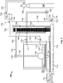
- FIG. 7 is a schematic diagram of an implementation of a spotting fluid testing system 700.
- the spotting fluid testing system 700 is used to test or validate a theoretical response of removing (for example, unsticking) of an object imbedded in a prepared mudcake sample.
- the system 700 may be used to test or validate a theoretical response to unsticking a portion of a wellbore tubular (for example, drill pipe or a portion of a drilling assembly) that is embedded in a mudcake of a wellbore.
- a wellbore tubular for example, drill pipe or a portion of a drilling assembly
- the spotting fluid testing system 700 is similar to the mudcake testing system 100 shown in FIG. 1 , but also includes a spotting fluid testing assembly 702, as illustrated in FIG. 7 . In example implementations, however, there may be components of mudcake testing system 100 that are not required in, or a part of, the spotting fluid testing system 700. Likewise, in example implementations, there may be components of spotting fluid testing system 700 that are not required in, or a part of, the mudcake testing system 100.
- the illustrated implementation of the spotting fluid testing assembly 702 includes a feeder tank 704 that holds a volume of spotting fluid 706 to be tested in the spotting fluid testing system 700.
- the feeder tank 704 is fluidly coupled to a test cell 750 with an input conduit 708 that includes an inlet 712 into the cell 750.
- the feeder tank is supported by a stand 736, at a vertical level above the inlet 712. At this vertical level above the inlet 712, spotting fluid 706 may be fed through the input conduit 708, through the inlet 712, and into the test cell 750 by a gravity feed.
- the spotting fluid testing assembly 702 also includes a collection tank 714 that can hold a volume of spent spotting fluid 716.
- the collection tank 714 is also fluidly coupled to the test cell 750 with an output conduit 718 that includes an outlet 722 from the cell 750. As shown, the collection tank 714 includes a drain 732.
- the inlet 712 is positioned vertically lower than the outlet 722 in the test cell 750.
- this vertical difference may allow the entry of spotting fluid 706 and the exit of the spent spotting fluid 716 (or overflow spotting fluid 706) out when the top of the spotting fluid 706 reaches a pre-defined height.
- the top of spotting fluid 706 (for example, the location of the outlet 722) may be about 10 mm or more above the top of the mudcake sample 715-member 745 contact point to keep the mudcake sample 715 immersed in the spotting fluid 706 during tests.
- the illustrated implementation of the spotting fluid testing assembly 702 also includes a gas cylinder 724 that holds a supply of pressurized gas therein.
- the gas cylinder 724 includes a pressure regulator 726 that controls a supply of pressurized gas 728 into the feed tank 704.
- the pressurized gas 728 may be circulated into the feed tank 704 to force feed the spotting fluid 706 (for example, by an increase in pressure in the tank 704) from the tank 704, through the input conduit 708, through the inlet 712, and into the test cell 750.
- the pressure regulator 726 fitted at an outlet of the gas cylinder 724 may allow the setting of a required pressure to push the spotting fluid 706 from the feeder tank 704 into the test cell 750.
- the illustrated spotting fluid testing assembly 702 includes multiple valves 734 that are positioned within the assembly 702 to fluidly isolate or fluidly couple, when closed or opened, respectively, the components of the assembly 702.
- one or more valves 736 are positioned in the input conduit 708 to regulate a flow of the spotting fluid 706 from the feed tank 704 into the test cell 750.
- One or more valves 736 are positioned in the output conduit 718 to regulate a flow of the spent spotting fluid 716 from the test cell 750 into the collection tank 714.
- a valve 734 is positioned on the drain 732 to regulate a flow of the spent spotting fluid 716 from the collection tank 714 (for example, for recycling, purification, disposal or otherwise).
- one or more of the valves 734 may be manually controlled to regulate a flow of fluid (for example, the spotting fluid 706, the spent spotting fluid 716, the pressurized gas 728, or otherwise) through the spotting fluid testing assembly 702.
- one or more of the valves 734 may be automatically controlled (for example, by the control system 710) to modulate to open or closed during operation of the spotting fluid testing assembly 702.
- a mudcake sample 715 represents a portion of a mudcake in a wellbore that is developed during drilling or other wellbore operations.
- the mudcake sample 715 may be prepared identical to, or substantially identical to, the mudcake sample 115 as described with reference to FIG. 1 .
- the mudcake sample 715 represents residue deposited on a permeable medium (for example, a wellbore wall) that develops when drilling fluid is deposited against the wellbore wall under pressure. Because liquid is able to pass through the permeable medium, a sticky substance, called a "mudcake,” may be left to form on the wellbore wall.
- the mudcake has certain properties based on, for instance, the drilling fluid used in the drilling operation. Such properties relate to the thickness (for example, which affects hydrocarbon production), toughness, slickness (for example, which affects an affinity to adhere or not to tubular drilling components), and permeability (for example, also affecting production). Mudcakes that form on permeable zones in the wellbore can cause stuck pipe and other drilling problems.
- the testing system 700 can be used to determine one or more properties of the spotting fluid 706 that can reduce an adhesion of a mudcake to, for example, a wellbore wall. The determination of such properties of the spotting fluid 706 may be used to select a particular spotting fluid to use for an unsticking operation (for example, to free a stuck pipe from a wellbore).
- the illustrated implementation of the spotting fluid testing system 700 includes a load cell 705 that is communicably coupled to the control system 710.
- load cells may be used as the load cell 705, including, without limitation, a uniaxial load cell, a triaxial load cell, a biaxial load cell, a strain-gauge load cell, a hydraulic load cell, or a pneumatic load cell.
- the load cell 705 is capable of applying 490.33 Newton (N) (50 kilograms-force (kgf)) or less of force in operation of the system 700.
- the load cell 705 includes carrier arm 720 mounted on a load stand 725.
- the load stand 725 operates to lower and raise the carrier arm 720, and by extension a testing member 745 mounted on a test leg 740 coupled to the carrier arm 720, with a variable mount of force.
- an upper position limiter 730a and a lower position limiter 730b is mounted adjacent the load stand 725 to provide upper and lower movement limits of the carrier arm 720 during operation of the spotting fluid testing system 700.
- the spotting fluid testing system 700 also includes the test cell 750.
- the test cell 750 can be similar or identical to the test cell 150, for example, an API test cell or high temperature - high pressure (HTHP) test cell into which a prepared mudcake sample 715 is placed.
- Example test cells can include: a Fann ® Instrument No. 101502980 or No. 101533370; an OFI Testing Equipment, Inc. 140-40 Water Loss Press 4 Unit, serial #14-15; or an OFI Testing Equipment, Inc. 170-00 OFITE HTHP Press, Single End Test Cell.
- the test cell 750 and the test cell 150 may be different test cells.
- the test cell 750 may have the same or similar inner and outer dimensions (for example, diameter, or width and length) as the test cell 150 but a lower height than the test cell 150.
- the mudcake sample 715 is placed on top of a filter 760, which in turn is placed on top of a screen 765 (for example, metallic screen).
- the illustrated test cell 750 includes an outlet 755 positioned at a bottom, for example, to allow liquid to drain from the mudcake sample 715 if necessary.
- the illustrated control system 710 comprises a processor based controller 770 (for example, CPU) that is communicably coupled to a data logger 775.
- the controller 770 includes an input peripheral (for example, keyboard, toggles, button, mouse, or otherwise) for use by an operator (for example, to input operational constraints) as well as an output peripheral.
- the controller 770 is coupled with the load cell 705 (for example, through one or more wires or wirelessly) to receive data output from the load cell 705 during operation of the spotting fluid testing system 700.
- data such as force applied by the load stand 725 (for example, upward) on the member 745 (for example, through the carrier arm 720 and the leg 740), as well as position of the member 745 (for example, initial position in contact in the mudcake sample 715, relative distance of the member 745 from an initial position, or both), may be transmitted to or received by the controller 770.
- the implementation of the load cell 705 includes a calibration platform 735.
- the calibration platform 735 receives a signal from the load cell 705 that represents the force applied on the test member 745 during operation of the testing system 700.
- the calibration platform 735 then calculates a relationship between the detected signal and the force.
- the load cell 705 detects and measures an electrical resistance signal that is proportional to the force applied to the test member 745.
- the electrical resistance signal is then converted to a force signal to be output by the control system 710.
- the data logger 775 includes an output device for display of the data (for example, force, displacement distance, or other data) sent to the controller 770 from the load cell 705.
- Example outputs include graphical representations of force versus displacement curves are shown for various spotting fluids 706 in FIGS. 9A-9C and 10A-10C .
- the mudcake sample 715 experiences an interface between the member 745 and the sample 715. More specifically bonds develop once the member 745 is inserted into the mudcake sample 715 that is positioned in the test cell 750. Generally, once an object, such as the member 745 that represents a wellbore tubular, is embedded into a matrix of a mudcake (for example, the mudcake sample 715), adhesive bonds develop between the object and the mudcake interface due to the alteration of free surface energy at the contacting surfaces of the mudcake sample 715 and the embedded object (for example, the member 745). The sticking bonds are the combined results of adhesive and cohesive bonds and are governed by the resultant effect of interfacial tension, Vander der Waal forces, inter-atomic and inter-molecular forces, hydrogen and ionic bonds, and otherwise.
- mudcakes deposited by various drilling systems have significantly different sticking bond characteristics.
- Such characteristics are sticking bond modulus (SBM) (for example, a rate of increase of a pull resistance of a mudcake) and ultimate sticking bond strength (USBS).
- SBM sticking bond modulus
- USBS ultimate sticking bond strength
- the member 745 embedded into mudcake sample 715 experiences interfacial adhesive bonds and cohesive matrix bonds that adhere the member 745 with the mudcake sample 715 (examples of such bonds are shown in FIG. 2 with respect to the sample 115). If such adhesive bonds and cohesive bonds are weak, then the member 745 is released more easily based on an upward force applied to the member 745 from the load stand 725 (for example, pulling the member 745 out of the sample 715). On the other hand, a mudcake sample 715 that creates strong adhesive bonds and cohesive bonds at the mudcake-member interface may require a higher upward pull (for example, by the load stand 725) to release from the mudcake sample 715.
- the member 745 comprises a spherically-shaped member.
- Other implementations of a mudcake testing system according to the present disclosure may include alternatively-shaped members, such as cylindrical, egg-shaped, or otherwise.
- the spherical member 745 is used to more accurately determine one or more properties (for example, SBM, USBS, or otherwise) of the mudcake sample 715 as compared to, for example, a tubular or cylindrically-shaped member.
- a wellbore component that sticks to a wellbore mudcake is typically cylindrical in cross section (for example, drill pipe, a drill string, or other tubular component)
- use of a cylindrical member may not provide accurate readings due to the sharp edges that would be present on a cylindrical member.
- the spherical member 745 in some aspects, may better represent a wellbore tubular for more accurate determination of the mudcake properties.
- the mudcake sample 715 is prepared, for example, according to the description of the preparation of the mudcake sample 115.
- the mudcake sample 715 may be prepared to more than 10 mm thickness, for instance, in the test cell 150.
- the mudcake sample 715 may not be prepared with a minimum filtration time of 30 minutes per API procedure, but instead, for example, the filtration time may be set longer to achieve the 10 mm thickness.
- the mudcake sample 715 may be placed in the test cell 750 (for example, if not prepared in the test cell 750). In some aspects, should the mudcake sample 715 be prepared in another test cell, such as test cell 150, the sample 715 may be washed gently with fresh water to remove the soft jelly-like mud material from the top of the mudcake sample 715 prior to placement in the test cell 750.
- operating parameters for the test of the spotting fluid 706 may be set.
- the control system 710 may be used to set all test parameters, record and plot the test data graphically, set the initial load and displacement reading to zero and define the rate of compression for embedding the member 745 into the mudcake sample 715, as well as set the pulling rate during a test.
- a pulling rate of 0.02 mm/sec may be used during the embedment and pulling phases of the test.
- the member 745 is embedded (for example, automatically) into the mudcake matrix using a controlled downward displacement of the spherical member 745 (for example, at a rate of 0.02 mm/sec) until a particular embedment depth of the member 745 into the mudcake sample 715 is reached.
- the embedment depth may be about 5 mm.
- a particular time duration (for example, about 2 minutes) may pass in order to stabilize the position of the member 745, the mudcake sample 715-member 745 interface, and the mudcake matrix material.
- the initial load and the starting depth are set at zero for the test. This step of the test may simulate the sticking event of a drill string into the mudcake matrix in a real wellbore environment.
- the spotting fluid 716 is circulated into the spotting fluid test cell 750.
- a particular depth of spotting fluid 716 may be achieved, such as, for example, until the top of the spotting fluid 706 reaches 10-15 mm above the top of the mudcake sample 715. If the spotting fluid 706 reaches the outlet 722, the fluid 706 may exit through the outlet 722 to collect into the collection tank 714. This step simulates the placement of spotting fluid in a stuck pipe zone in a wellbore.
- the spotting fluid 706 in the test cell 750 may be allowed a particular time duration to soak into the sample 715.
- allowing a soaking time for the spotting fluid 706 may de-bond, degrade, or damage the adhesive and cohesive forces causing sticking of the member 745 to the mudcake 715.
- the particular time duration may be minutes, hours, days, or even longer. In some examples, the time duration may be between 5 and 20 hours, 12 and 16 hours, or other time duration.
- an application of pulling force on the member 745 away from the mudcake sample 715 may be initiated.
- a constant pulling rate (for example, of 0.02 mm/sec) may be applied during the upward displacement of the embedded member 745.
- a force versus displacement curve may be recorded automatically by the control system 710 that also controls the operation of the apparatus during the test.
- the control system 710 may also record all test data and display the data on-screen in a graphical format.
- the operation may be terminated after recording a maximum pulling force and the recovery of the member 745 from the mudcake sample 715.
- the spotting fluids used in the experimental tests are described in Table 5. Each particular spotting fluid (numbered 1, 2, and 3) was used in a test operation (as described previously), and each particular spotting fluid was tested at two particular soaking times: 6 hours and 16 hours.
- the prepared mudcake sample used during the testing of the spotting fluid testing assembly 702 was a KCl-Polymer mudcake as described in Table 2.
- the graphical results of the experimental tests are shown in the force versus displacement curves of FIGS. 9A-9C (for the 6 hour soaking time) and FIGS.
- the spotting fluid is designed based on concentration of additives required for one or 100 barrels of the spotting fluid final product.
- the liquid additive concentrations are in barrel or gallon and the solids additive concentrations are in pounds (lbs).
- 350 cubic centimeters (cc) or its multiples are produced by adding solids and/or liquid components of a spotting fluid formulation.
- the liquid is in cubic centimeters and the solids are measured in grams (gm).
- a gram of solid additive in a lab formulation mixed with 350 cc spotting fluid in the lab equals to the pounds of solids product in one (1) barrel of spotting fluid in the field.
- 1 gm in the lab will be equivalent to 1 pound in the field.
- several of the components (for example, EZ-SPOT, Pipe Lax) refer to product names known in the oil and gas industry.
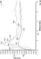
- FIG. 8 is a graphical representation that illustrates a pulling force relative to upward displacement during testing of the KCl-Polymer mudcake sample without application of a spotting fluid. For example, first a pulling test without a spotting fluid in the spotting fluid test cell was performed to get a bench mark value of SBM and the ultimate sticking bond strength of the mudcake sample. This step of the test simulates the attempt to recover a stuck pipe without placing a spotting fluid, which may or may not be successful depending on the strength of the sticking bonds formed between the mudcake and pipe contact surfaces.
- the characteristic values of the original mudcake was then used to evaluate the performance of various spotting fluids by determining the % reduction in SBM and the USBS of the mudcake sample due to de-bonding, dehydration, damaging, and lubricating effect of the spotting fluid.
- FIG. 8 shows a graph 800 of the triplicate tests for the KCl polymer mudcake tested without spotting fluid, and includes a y-axis 802 which represents force in kilograms, and an x-axis 804 that represents pull distance, in millimeters, of the member from an initial position embedded in the mudcake sample.
- Curves 806a-806c show the result of three independent implementations of the test operation, which, without spotting fluid, may be similar or identical to method 400 described previously.
- the numerical results of the triplicate tests shown in plots 806a-806c are shown in Table 6. TABLE 6 Test No.
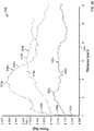
- FIGS. 9A-9C are graphical representations that illustrate results of a pulling test (performed in triplicate) in which Spotting Fluids 1, 2, and 3 (described in Table 5) have been applied to a mudcake sample, which has subsequently been soaked with the particular spotting fluid for 6 hours prior to initiation of each pulling test.
- graph 900 in FIG. 9A this graph illustrates a triplicate test of Spotting Fluid #1, after soaking the KCl-Polymer mudcake sample for 6 hours.
- Graph 900 includes a y-axis 902 which represents force in kilograms, and an x-axis 904 that represents pull distance, in millimeters, of the member from an initial position embedded in the mudcake sample.
- Curves 906a-906c show the result of three independent implementations of the test operation, described with reference to FIG. 7 and the spotting fluid testing system 700.
- the numerical results of the triplicate tests shown in plots 906a-906c are shown in Table 7.
- graph 920 in FIG. 9B illustrates a triplicate test of Spotting Fluid #2, after soaking the KCl-Polymer mudcake sample for 6 hours.
- Graph 920 includes a y-axis 922 which represents force in kilograms, and an x-axis 924 that represents pull distance, in millimeters, of the member from an initial position embedded in the mudcake sample.
- Curves 926a-926c show the result of three independent implementations of the test operation, described with reference to FIG. 7 and the spotting fluid testing system 700. The numerical results of the triplicate tests shown in plots 926a-926c are shown in Table 8. TABLE 8 Test No.
- graph 940 in FIG. 9C illustrates a triplicate test of Spotting Fluid #3, after soaking the KCl-Polymer mudcake sample for 6 hours.
- Graph 940 includes a y-axis 942 which represents force in kilograms, and an x-axis 944 that represents pull distance, in millimeters, of the member from an initial position embedded in the mudcake sample.
- Curves 946a-946c show the result of three independent implementations of the test operation, described with reference to FIG. 7 and the spotting fluid testing system 700. The numerical results of the triplicate tests shown in plots 946a-946c are shown in Table 9. TABLE 9 Test No.
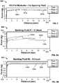
- FIGS. 10A-10C are graphical representations that illustrate results of a pulling test (performed in triplicate) in which Spotting Fluids 1, 2, and 3 (described in Table 5) have been applied to a mudcake sample, which has subsequently been soaked with the particular spotting fluid for 16 hours prior to initiation of each pulling test.
- graph 1000 in FIG. 10A this graph illustrates a triplicate test of Spotting Fluid #1, after soaking the KCl-Polymer mudcake sample for 16 hours.
- Graph 1000 includes a y-axis 1002 which represents force in kilograms, and an x-axis 1004 that represents pull distance, in millimeters, of the member from an initial position embedded in the mudcake sample.
- Curves 1006a-1006c show the result of three independent implementations of the test operation, described with reference to FIG. 7 and the spotting fluid testing system 700.
- the numerical results of the triplicate tests shown in plots 1006a-1006c are shown in Table 10.
- graph 1020 in FIG. 10B illustrates a triplicate test of Spotting Fluid #2, after soaking the KCl-Polymer mudcake sample for 16 hours.
- Graph 1020 includes a y-axis 1022 which represents force in kilograms, and an x-axis 1024 that represents pull distance, in millimeters, of the member from an initial position embedded in the mudcake sample.
- Curves 1026a-1026c show the result of three independent implementations of the test operation, described with reference to FIG. 7 and the spotting fluid testing system 700. The numerical results of the triplicate tests shown in plots 1026a-1026c are shown in Table 11. TABLE 11 Test No.
- graph 1040 in FIG. 10C illustrates a triplicate test of Spotting Fluid #3, after soaking the KCl-Polymer mudcake sample for 16 hours.
- Graph 1040 includes a y-axis 1042 which represents force in kilograms, and an x-axis 1044 that represents pull distance, in millimeters, of the member from an initial position embedded in the mudcake sample.
- Curves 1046a-1046c show the result of three independent implementations of the test operation, described with reference to FIG. 7 and the spotting fluid testing system 700. The numerical results of the triplicate tests shown in plots 1046a-1046c are shown in Table 12. TABLE 12 Test No.
- Correlation Coefficient includes numerical values between 0 and 1.
- a Correlation Coefficient indicates the significance of test for relationship between two continuous variables: . It indicates the strength of relationship between the parameters. The higher the Correlation Coefficient, better the relationship between the two test parameters. A correlation value of greater than 0.9 is considered very strong relation. A perfect relation between two test parameters is indicated by a Correlation Coefficient equal to 1. In this example, the Correlation Coefficient indicates the significance of the relationship between the SBM and the USBS for the triplicate tests.
- Table 13 shows the average SBM and USBS values and percentage reduction of such values relative to the same variables that resulted from the "no spotting fluid" test described in FIG. 8 and Table 6.
- TABLE 13 Spotting Fluid-Soak Time Average SBM (N/mm (kgf/mm)) Average USBS (N (kgf)) SBM Reduction (%) USBS Reduction (%) None-NA 375.01 (38.24) 58.94 (6.010) ---- ---- Spotting Fluid #1 - 6 hr. 332.64 (33.92) 27.56 (2.810) 11.30 53.24 Spotting Fluid #2 - 6 hr. 222.41 (22.68) 12.45 (1.270) 40.69 78.87 Spotting Fluid #3 - 6 hr.
- calculation of a percent reduction of SBM and USBS after 16 hours soaking time indicates more than a 41 and 75% reduction of SBM and the USBS respectively.
- the data may, therefore, indicate that the Spotting Fluid #1 may reduce the SBM and USBS of the mudcakes significantly after 6 and 16 hours of soaking time.
- the 6 hours soaking time may not be sufficient enough for complete interaction in the presence of Spotting Fluid #1. This result may also indicate a requirement of a longer time of interactions for the Spotting Fluid #1 to damage and degrade the sticking bonds.
- calculation of a percent reduction of SBM and USBS after 16 hours soaking time indicates more than 20 and 70% reduction of SBM and the USBS, respectively.
- the data may, therefore, indicate that the Spotting Fluid #2 is able to reduce the SBM and USBS of the mudcakes significantly after 6 and 16 hours of soaking time.
- the tests indicate somewhat lower reduction of SBM and USBS after 16 hours soaking time versus 6 hours soaking time. This may indicate a reversal of degradation and damaging effect due to an interaction hardening effect on the sticking bonds in the presence of Spotting Fluid #2. This result may also indicate that the soaking time above an optimum soaking period has no technical benefit.
- a longer soaking time for some spotting fluids may need result in a higher required pulling force than the pulling force required after an optimum soaking time due to the interaction hardening effect of the spotting fluid.
- calculation of a percent reduction of SBM and USBS after 16 hours soaking time indicates more than 39 and 90% reduction of SBM and the USBS, respectively. This result indicates little or negligible reduction in the SBM and USBS after 16 hours soaking time versus 6 hours soaking time.
- the data may indicate that the Spotting Fluid #3 is able to reduce the SBM and USBS of the mudcakes significantly within a short time interval such as 6 hours and less.
- the data may further indicate that the longer soaking time has no or insignificant benefit for some spotting fluids due to their full and complete interaction potential within an optimum time. This result indicates the requirement of maximum 6 hours or less soaking time for the Spotting Fluid #3.
- the Spotting Fluid #2 test results may provide certain information. First, such results may indicate a need of a shorter time of interaction between the fluid and the mudcake sample to cause damage, degradation, or weakening of sticking bonds of the mudcake-member interface. The data may also indicate that the 6 hours soaking time is enough for the Spotting Fluid #2. Second, the data may indicate the long term interaction hardening of the sticking bonds in the presence of Spotting Fluid #2. This is reflected by a higher SBM and USBS values after 16 hours of soaking time compared to 6 hours soaking time.
- the Spotting Fluid #2 may have better performance in weakening the sticking bonds and releasing the embedded member from the mudcake sample, and thus the better spotting fluid for debonding a stuck pipe from a mudcake in a wellbore.
- Data for the Spotting Fluid #3 tests may also provide information.
- First, such results may indicate a need of a shorter time of interactions to cause damage, degradation, or weakening of sticking bonds of the mudcake-member interface.
- the data may also indicate that 6 hours or less soaking time is enough for the Spotting Fluid #3 for sufficient degradation of the sticking bonds formed in the member-mudcake interface.
- Second, the data may indicate the absence of any long term interaction hardening effect in the presence of the Spotting Fluid #3. This is reflected by negligible changes in SBM and USBS values after 16 hours of soaking time compared to 6 hours soaking time.
- Test data resulting from operations with the spotting fluid testing system 700 may be predictively used (for example, by the control system 710) to determine or help determine real-world operations.
- the control system 710 may predict, based on test results using one or more spotting fluids, that a particular spotting fluid should be used to help unstick a drill pipe or other tubular member from a wellbore with a particular mudcake composition.
- the control system 710 may predict, based on test results from one or more spotting fluids, that a particular spotting fluid should soak a mudcake into which a drill pipe or other tubular member is stuck for a particular time duration before attempting to free the tubular member.
- FIG. 11 is a schematic diagram of a control system (or controller) 1100.
- the system 1100 can be used for the operations described in association with any of the computer-implemented methods described previously as or as part of the control system 110, 710, or other controllers described in this disclosure.
- the system 1100 may be used in providing local control for a mudcake testing system as shown in FIGS. 1 and 7 , remote control or monitoring of a mudcake testing system (for example, for a system placed at a wellsite location), or otherwise.
- the system 1100 is intended to include various forms of digital computers, such as laptops, desktops, workstations, personal digital assistants, servers, blade servers, mainframes, and other appropriate computers.
- the system 1100 can also include mobile devices, such as personal digital assistants, cellular telephones, smartphones, and other similar computing devices.
- the system can include portable storage media, such as, Universal Serial Bus (USB) flash drives.
- USB flash drives may store operating systems and other applications.
- the USB flash drives can include input/output components, such as a wireless transmitter or USB connector that may be inserted into a USB port of another computing device.
- the system 1100 includes a processor 1110, a memory 1120, a storage device 1130, and an input/output device 1140. Each of the components 1110, 1120, 1130, and 1140 are interconnected using a system bus 1150.
- the processor 1110 is capable of processing instructions for execution within the system 1100.
- the processor may be designed using any of a number of architectures.
- the processor 1110 may be a CISC (Complex Instruction Set Computers) processor, a RISC (Reduced Instruction Set Computer) processor, or a MISC (Minimal Instruction Set Computer) processor.
- the processor 1110 is a single-threaded processor. In another implementation, the processor 1110 is a multi-threaded processor.
- the processor 1110 is capable of processing instructions stored in the memory 1120 or on the storage device 1130 to display graphical information for a user interface on the input/output device 1140.
- the memory 1120 stores information within the system 1100.
- the memory 1120 is a computer-readable medium.
- the memory 1120 is a volatile memory unit.
- the memory 1120 is a non-volatile memory unit.
- the control modules herein may not include a memory module 1120.
- the storage device 1130 is capable of providing mass storage for the system 1100.
- the storage device 1130 is a computer-readable medium.
- the storage device 1130 may be a floppy disk device, a hard disk device, an optical disk device, or a tape device.
- the input/output device 1140 provides input/output operations for the system 1100.
- the input/output device 1140 includes a keyboard or pointing device.
- the input/output device 1140 includes a display unit for displaying graphical user interfaces.
- the features described can be implemented in digital electronic circuitry, or in computer hardware, firmware, software, or in combinations of them.
- the apparatus can be implemented in a computer program product tangibly embodied in an information carrier, for example, in a machine-readable storage device for execution by a programmable processor; and method steps can be performed by a programmable processor executing a program of instructions to perform functions of the described implementations by operating on input data and generating output.
- the described features can be implemented advantageously in one or more computer programs that are executable on a programmable system including at least one programmable processor coupled to receive data and instructions from, and to transmit data and instructions to, a data storage system, at least one input device, and at least one output device.
- a computer program is a set of instructions that can be used, directly or indirectly, in a computer to perform a certain activity or bring about a certain result.
- a computer program can be written in any form of programming language, including compiled or interpreted languages, and it can be deployed in any form, including as a stand-alone program or as a module, component, subroutine, or other unit suitable for use in a computing environment.
- Suitable processors for the execution of a program of instructions include, by way of example, both general and special purpose microprocessors, and the sole processor or one of multiple processors of any kind of computer.
- a processor receives instructions and data from a read-only memory or a random access memory or both.
- the essential elements of a computer are a processor for executing instructions and one or more memories for storing instructions and data.
- a computer includes, or is operatively coupled to communicate with, one or more mass storage devices for storing data files; such devices include magnetic disks, such as internal hard disks and removable disks; magneto-optical disks; and optical disks.
- Storage devices suitable for tangibly embodying computer program instructions and data include all forms of non-volatile memory, including by way of example semiconductor memory devices, such as EPROM, EEPROM, and flash memory devices; magnetic disks such as internal hard disks and removable disks; magneto-optical disks; and CD-ROM and DVD-ROM disks.
- semiconductor memory devices such as EPROM, EEPROM, and flash memory devices
- magnetic disks such as internal hard disks and removable disks
- magneto-optical disks and CD-ROM and DVD-ROM disks.
- the processor and the memory can be supplemented by, or incorporated in, ASICs (application-specific integrated circuits).
- ASICs application-specific integrated circuits
- the features can be implemented on a computer having a display device such as a CRT (cathode ray tube) or LCD (liquid crystal display) monitor for displaying information to the user and a keyboard and a pointing device such as a mouse or a trackball by which the user can provide input to the computer. Additionally, such activities can be implemented via touchscreen flat-panel displays and other appropriate mechanisms.
- a display device such as a CRT (cathode ray tube) or LCD (liquid crystal display) monitor for displaying information to the user and a keyboard and a pointing device such as a mouse or a trackball by which the user can provide input to the computer.
- a keyboard and a pointing device such as a mouse or a trackball by which the user can provide input to the computer.
- activities can be implemented via touchscreen flat-panel displays and other appropriate mechanisms.
- the features can be implemented in a control system that includes a back- end component, such as a data server, or that includes a middleware component, such as an application server or an Internet server, or that includes a front-end component, such as a client computer having a graphical user interface or an Internet browser, or any combination of them.
- the components of the system can be connected by any form or medium of digital data communication such as a communication network. Examples of communication networks include a local area network (“LAN”), a wide area network (“WAN”), peer-to-peer networks (having ad-hoc or static members), grid computing infrastructures, and the Internet.
- LAN local area network
- WAN wide area network
- peer-to-peer networks having ad-hoc or static members
- grid computing infrastructures and the Internet.
- example operations, methods, or processes described herein may include more steps or fewer steps than those described. Further, the steps in such example operations, methods, or processes may be performed in different successions than that described or illustrated in the figures. Accordingly, other implementations are within the scope of the following claims.
Landscapes
- Life Sciences & Earth Sciences (AREA)
- Geology (AREA)
- Engineering & Computer Science (AREA)
- Mining & Mineral Resources (AREA)
- Physics & Mathematics (AREA)
- General Life Sciences & Earth Sciences (AREA)
- Environmental & Geological Engineering (AREA)
- Fluid Mechanics (AREA)
- Geochemistry & Mineralogy (AREA)
- General Physics & Mathematics (AREA)
- Analytical Chemistry (AREA)
- Chemical & Material Sciences (AREA)
- Marine Sciences & Fisheries (AREA)
- Health & Medical Sciences (AREA)
- Biochemistry (AREA)
- General Health & Medical Sciences (AREA)
- Immunology (AREA)
- Pathology (AREA)
- Sampling And Sample Adjustment (AREA)
Claims (15)
- Verfahren (400), umfassend:Positionieren (404) eines Elements einer Prüfvorrichtung in einer vorbereiteten Filterkuchenprobe (715) in einer spezifizierten Tiefe der Filterkuchenprobe (715), wobei die Filterkuchenprobe (715) mit einer Bohrflüssigkeit verbunden ist und eine spezifizierte Dicke umfasst;Druckbeaufschlagen eines Spotting-Fluids (706) in einem Vorratstank (704) mit einem druckbeaufschlagten Gas (728), das in einem Gastank in Fluidverbindung mit dem Vorratstank (704) gespeichert ist;Zirkulierenlassen eines druckbeaufschlagten Stroms des Spotting-Fluids (706) vom Vorratstank (704) zu einer Prüfzelle der Prüfvorrichtung, um mit der vorbereiteten Filterkuchenprobe (715) in der Prüfzelle der Prüfvorrichtung in Kontakt zu treten;Einweichen der vorbereiteten Filterkuchenprobe (715) im Spotting-Fluid (706) für eine spezifizierte Zeitdauer;Detektieren (412) einer auf das Element ausgeübten Kraft relativ zu einem Verschiebeweg des Elements von der spezifizierten Tiefe in der Filterkuchenprobe (715) durch die Prüfvorrichtung während der Entfernung des Elements aus der Filterkuchenprobe (715) nach der spezifizierten Zeitdauer;Aufzeichnen (414) der detektierten Kraft relativ zum Verschiebeweg mit der Prüfvorrichtung; undBestimmen (416) einer oder mehrerer Eigenschaften, die mit der Filterkuchenprobe (715) assoziiert sind, mit der Prüfvorrichtung basierend auf der aufgezeichneten Kraft relativ zum Verschiebeweg.
- Verfahren (400) nach Anspruch 1, ferner umfassend ein Sammeln eines Überlaufs des Spotting-Fluids (706), das aus der Prüfzelle strömt.
- Verfahren (400) nach Anspruch 1, ferner umfassend ein Regeln eines Drucks des druckbeaufschlagten Gases (728), das vom Gastank zum Vorratstank (704) zirkuliert.
- Verfahren (400) nach Anspruch 1, ferner umfassend ein Einleiten (408) der Entfernung des Elements aus der Filterkuchenprobe (715) durch die Kraft, die durch die Prüfvorrichtung auf das Element ausgeübt wird.
- Verfahren nach Anspruch 1, wobei spezifizierte Dicke 10 mm beträgt, und die spezifizierte Tiefe 5 mm beträgt.
- Verfahren (400) nach Anspruch 1, ferner umfassend ein Entfernen (410) des Elements aus der Filterkuchenprobe (715) durch die Kraft, die durch die Prüfvorrichtung auf das Element ausgeübt wird, wobei das Entfernen des Elements aus der Filterkuchenprobe (715) durch die Kraft, die durch die Prüfvorrichtung auf das Element ausgeübt wird, optional ein Entfernen des Elements aus der Filterkuchenprobe (715) mit einer konstanten Entfernungsgeschwindigkeit umfasst.
- Verfahren (400) nach Anspruch 1, ferner umfassend ein Halten (406) des Elements für einen spezifizierten Zeitraum in der Filterkuchenprobe (715) vor dem Zirkulierenlassen des Spotting-Fluids (706), wobei der spezifizierte Zeitraum optional 2 Minuten beträgt.
- Verfahren (400) nach Anspruch 1, ferner umfassend ein Bestimmen (412) mindestens einer der einen oder der mehreren Eigenschaften wenigstens zum Teil basierend auf der grafischen Aufzeichnung (414) der auf das Element ausgeübten Kraft relativ zum Verschiebeweg.
- Verfahren (400) nach Anspruch 1, ferner umfassend ein Durchführen einer Aktion wenigstens zum Teil basierend auf der einen oder den mehreren bestimmten Eigenschaften, wobei die Aktion mindestens eines von Folgendem umfasst:Auswählen einer Bohrflüssigkeit, die bei einem Bohrvorgang verwendet werden soll;Auswählen eines spezifischen Spotting-Fluids (706), das bei einem Vorgang zur Entfernung eines festklebenden Rohres verwendet werden soll; oderBestimmen einer Rückgewinnbarkeit eines rohrförmigen Elements, das in einem Bohrloch festklebt.
- Spotting-Fluid-Prüfsystem (700), umfassend:eine Prüfvorrichtung, die umfasst:einen Filterkuchenhalter, der zum Festhalten einer Filterkuchenprobe (715) in einer unbeweglichen Position ausgelegt ist;eine Lastzelle (705); undein Prüfelement (745), das mit der Lastzelle (705) gekoppelt ist;einen Vorratstank (704), der zum Zirkulierenlassen eines Stroms des Spotting-Fluids (706) vom Vorratstank (704) zur Prüfzelle positioniert ist;einen Gastank, der ein druckbeaufschlagtes Gas (728) speichert, wobei der Gastank mit dem Vorratstank (704) in Fluidverbindung steht; undein Steuersystem (710), das mit der Prüfvorrichtung kommunikativ gekoppelt und zum Durchführen von Vorgängen ausgelegt ist, die umfassen:Steuern der Lastzelle (705) zum Positionieren des Elements in der Filterkuchenprobe (715) in einer spezifizierten Tiefe der Filterkuchenprobe (715);Steuern eines oder mehrerer Ventile (734, 736) zum Zirkulierenlassen des druckbeaufschlagten Gases (728) zum Vorratstank (704), um einen druckbeaufschlagten Strom eines Spotting-Fluids (706) aus dem Vorratstank (704) zur Prüfzelle zu erzeugen;Steuern eines oder mehrerer Ventile (734, 736) der Prüfvorrichtung zum Zirkulierenlassen des Spotting-Fluids (706), um mit der Filterkuchenprobe (715) in einer Prüfkammer der Prüfvorrichtung in Kontakt zu treten und diese darin einzuweichen;Steuern der Lastzelle (705) zum Einleiten der Entfernung des Elements aus der Filterkuchenprobe (715) durch eine Kraft, die durch die Lastzelle (705) auf das Element ausgeübt wird, nach einer spezifizierten Einweichzeitdauer;Detektieren einer auf das Element ausgeübten Kraft relativ zu einem Verschiebeweg des Elements von der spezifizierten Tiefe in der Filterkuchenprobe (715) durch die Prüfvorrichtung während der Entfernung des Elements aus der Filterkuchenprobe (715);Aufzeichnen der detektierten Kraft relativ zum Verschiebeweg mit der Prüfvorrichtung; undBestimmen einer oder mehrerer Eigenschaften der Filterkuchenprobe (715) basierend auf der aufgezeichneten Kraft relativ zum Verschiebeweg.
- Spotting-Fluid-Prüfsystem (700) nach Anspruch 10, ferner umfassend einen Sammeltank, der mit der Prüfzelle in Fluidverbindung steht, wobei das Steuersystem (710) ferner zum Durchführen von Vorgängen ausgelegt ist, die umfassen:
Steuern eines oder mehrerer Ventile (734, 736) der Prüfvorrichtung zum Zirkulierenlassen eines Überlaufs des Spotting-Fluids (706) aus der Prüfzelle zum Sammeltank. - Spotting-Fluid-Prüfsystem (700) nach Anspruch 10, wobei das Steuersystem (710) ferner zum Durchführen von Vorgängen ausgelegt ist, die ein Steuern eines Druckreglers (726) des Gastanks zum Anpassen eines Drucks des druckbeaufschlagten Gases (728) umfassen, das vom Gastank zum Vorratstank (704) zirkuliert.
- Spotting-Fluid-Prüfsystem (700) nach Anspruch 10, wobei das Steuersystem (710) ferner zum Durchführen von Vorgängen ausgelegt ist, die ein Einleiten der Entfernung des Elements aus der Filterkuchenprobe (715) durch die Kraft umfassen, die durch die Prüfvorrichtung auf das Element ausgeübt wird.
- Spotting-Fluid-Prüfsystem (700) nach Anspruch 10, wobei das Steuersystem (710) ferner zum Durchführen von Vorgängen ausgelegt ist, die ein Entfernen des Elements aus der Filterkuchenprobe (715) durch die Kraft umfassen, die durch die Prüfvorrichtung auf das Element ausgeübt wird, wobei das Entfernen des Elements aus der Filterkuchenprobe (715) durch die Kraft, die durch die Prüfvorrichtung auf das Element ausgeübt wird, optional ein Entfernen des Elements aus der Filterkuchenprobe (715) mit einer konstanten Entfernungsgeschwindigkeit umfasst.
- Spotting-Fluid-Prüfsystem (700) nach Anspruch 10, wobei das Element ein kugelförmiges Element umfasst, und/oder wobei die eine oder die mehreren Eigenschaften der Filterkuchenprobe (715) einen Klebebindungsmodul (SBM) und eine Klebebindungs-Endfestigkeit (USBS) umfassen.
Applications Claiming Priority (3)
| Application Number | Priority Date | Filing Date | Title |
|---|---|---|---|
| US201562131048P | 2015-03-10 | 2015-03-10 | |
| US15/050,916 US10113422B2 (en) | 2015-03-10 | 2016-02-23 | Determining spotting fluid properties |
| PCT/US2017/016123 WO2017146884A1 (en) | 2015-03-10 | 2017-02-02 | Determining spotting fluid properties |
Publications (2)
| Publication Number | Publication Date |
|---|---|
| EP3420188A1 EP3420188A1 (de) | 2019-01-02 |
| EP3420188B1 true EP3420188B1 (de) | 2022-05-18 |
Family
ID=56886632
Family Applications (1)
| Application Number | Title | Priority Date | Filing Date |
|---|---|---|---|
| EP17704947.5A Active EP3420188B1 (de) | 2015-03-10 | 2017-02-02 | Bestimmung der eigenschaften von ausfleckungsflüssigkeiten |
Country Status (5)
| Country | Link |
|---|---|
| US (2) | US10113422B2 (de) |
| EP (1) | EP3420188B1 (de) |
| CA (1) | CA3015292C (de) |
| SA (1) | SA518392246B1 (de) |
| WO (1) | WO2017146884A1 (de) |
Families Citing this family (3)
| Publication number | Priority date | Publication date | Assignee | Title |
|---|---|---|---|---|
| US10113422B2 (en) * | 2015-03-10 | 2018-10-30 | Saudi Arabian Oil Company | Determining spotting fluid properties |
| CN110174350B (zh) * | 2019-06-12 | 2021-11-26 | 湖北省路桥集团有限公司 | 一种黏土真粘聚力的测试装置及测试方法 |
| CN115127995B (zh) * | 2022-07-27 | 2025-01-28 | 中国石油化工股份有限公司 | 用于测试钻井液泥饼与井壁之间粘附强度测试装置及方法 |
Family Cites Families (18)
| Publication number | Priority date | Publication date | Assignee | Title |
|---|---|---|---|---|
| US3410797A (en) | 1964-11-13 | 1968-11-12 | Exxon Research Engineering Co | Drilling muds |
| US4458528A (en) | 1982-12-30 | 1984-07-10 | Mobil Oil Corporation | Stickometer |
| US4491181A (en) | 1983-03-31 | 1985-01-01 | Gulf Research And Development Co. | Method of freeing stuck drill string using spotting fluid |
| US4829816A (en) * | 1987-11-06 | 1989-05-16 | Standard Oil Production Company | Method and apparatus for testing spotting fluids for releasing stuck drill pipe |
| FR2642840B1 (fr) | 1989-02-09 | 1993-06-25 | Total Petroles | Procede et cellule de mesure des coefficients d'adherence et de frottement d'un fluide de forage |
| US5260268A (en) * | 1991-07-18 | 1993-11-09 | The Lubrizol Corporation | Methods of drilling well boreholes and compositions used therein |
| GB2275342B (en) | 1993-02-19 | 1996-08-21 | Pumptech Nv | Apparatus and method for measuring the sticking tendency of drilling mud |
| US5637795A (en) * | 1995-11-01 | 1997-06-10 | Shell Oil Company | Apparatus and test methodology for measurement of bit/stabilizer balling phenomenon in the laboratory |
| US5676213A (en) | 1996-04-10 | 1997-10-14 | Schlumberger Technology Corporation | Method and apparatus for removing mudcake from borehole walls |
| FR2758185B1 (fr) | 1997-01-09 | 1999-07-02 | Schlumberger Cie Dowell | Dispositif et methode de mesure de caracteristiques d'un fluide petrolier ou analogue |
| FR2785991B1 (fr) | 1998-11-12 | 2002-09-13 | Dowell Schlumberger Services | Dispositif et methode de mesure de caracteristiques d'un fluide petrolier ou analogue |
| US6267186B1 (en) | 1999-06-14 | 2001-07-31 | Spectral, Inc. | Spotting fluid and method of treating a stuck pipe |
| US7493803B2 (en) | 2004-03-23 | 2009-02-24 | Benthic Geotech Pty Ltd. | Ball penetrometer for soft soils testing |
| US8101555B2 (en) | 2009-04-30 | 2012-01-24 | Rayborn Sr Jerry | Spotting fluids containing syrups |
| US9835608B2 (en) | 2012-12-20 | 2017-12-05 | Saudi Arabian Oil Company | Method for assessing ablation modulai of mudcakes to predict ease of mudcake removal or cleaning efficiency of cleaning/washing/spacer fluids |
| CN105051518B (zh) | 2012-12-21 | 2018-11-27 | 蓝帜株式会社 | 粘度测定方法以及粘度测定装置 |
| US20160266030A1 (en) * | 2015-03-10 | 2016-09-15 | Saudi Arabian Oil Company | Determining Mudcake Properties |
| US10113422B2 (en) * | 2015-03-10 | 2018-10-30 | Saudi Arabian Oil Company | Determining spotting fluid properties |
-
2016
- 2016-02-23 US US15/050,916 patent/US10113422B2/en active Active
-
2017
- 2017-02-02 EP EP17704947.5A patent/EP3420188B1/de active Active
- 2017-02-02 WO PCT/US2017/016123 patent/WO2017146884A1/en not_active Ceased
- 2017-02-02 CA CA3015292A patent/CA3015292C/en active Active
-
2018
- 2018-08-19 SA SA518392246A patent/SA518392246B1/ar unknown
- 2018-09-14 US US16/132,250 patent/US10472958B2/en active Active
Also Published As
| Publication number | Publication date |
|---|---|
| SA518392246B1 (ar) | 2022-05-25 |
| CA3015292C (en) | 2022-10-18 |
| US20190017376A1 (en) | 2019-01-17 |
| WO2017146884A1 (en) | 2017-08-31 |
| US10472958B2 (en) | 2019-11-12 |
| US10113422B2 (en) | 2018-10-30 |
| CA3015292A1 (en) | 2017-08-31 |
| EP3420188A1 (de) | 2019-01-02 |
| US20160265992A1 (en) | 2016-09-15 |
Similar Documents
| Publication | Publication Date | Title |
|---|---|---|
| EP3268734B1 (de) | Bestimmung von schlammkucheneigenschaften | |
| US10472958B2 (en) | Determining spotting fluid properties | |
| Shi et al. | A brittleness index evaluation method for weak-brittle rock by acoustic emission technique | |
| CN104990800B (zh) | 测试水力压裂液中固体支撑剂支撑效果的装置及其方法 | |
| US9388332B2 (en) | Chemically tagged polymers for simplified quantification and related methods | |
| CA3082548C (en) | Strain energy-based method and apparatus to determine the coefficient of resilience of lost circulation materials | |
| Hol et al. | Long-term compaction behavior of Permian sandstones-An investigation into the mechanisms of subsidence in the Dutch Wadden Sea | |
| Reid et al. | Differential-sticking mechanisms and a simple wellsite test for monitoring and optimizing drilling mud properties | |
| Ezeakacha et al. | Investigating Impact of Rock Type and Lithology on Mud Invasion and Formation Damage | |
| Cuss et al. | An experimental study of the potential for fault reactivation during changes in gas and pore-water pressure | |
| Roijmans et al. | Evaluating the sealing performance of plug and abandonment cement systems under downhole conditions | |
| Amanullah et al. | Method and apparatus to reduce the probability of differential sticking | |
| CN204855265U (zh) | 测试水力压裂液中固体支撑剂支撑效果的装置 | |
| Al-Mujalhem et al. | The effect of weighting agents on sandstone formation damage from water-based drilling fluids | |
| Reid et al. | Mechanisms of differential sticking and a simple well site test for monitoring and optimizing drilling mud properties | |
| Xiao et al. | Removal of ilmenite oil-based filter cake under HP/HT conditions using hydrochloric acid | |
| Konate et al. | Application of an innovative drilling simulator set up to test inhibitive mud systems for drilling shales | |
| Amanullah et al. | Novel method and apparatus for sticking fluid performance evaluation | |
| Crawford et al. | Textural controls on constitutive behavior in unconsolidated sands: micromechanics and cap plasticity | |
| NO317874B1 (no) | Fremgangsmate for a male karakteristikkene for boreslam eller tilsvarende fluid | |
| Gao et al. | Continued improvements on high-pressure/high-temperature drilling performance on wells with extremely narrow drilling windows-experiences from mud formulation to operational practices, shearwater project | |
| Amanullah | Experimental determination of adhesive-cohesive bond strength (ACBS) and adhesion-cohesion modulus (ACM) of Mudcakes | |
| AlSayed Omar et al. | Advanced Lost Circulation Solution: A Highly Thixotropic Cement System Pumped through BHA for Efficient Lost Circulation Management | |
| Alameen et al. | An experimental study to control sand production in weakly consolidated sandstone formations: A chemical approach on formation strength | |
| Ezeakacha | Dynamic Drilling Fluids Loss and Filtration: Impact of Dynamic Wellbore Conditions and Wellbore Strengthening Implications |
Legal Events
| Date | Code | Title | Description |
|---|---|---|---|
| STAA | Information on the status of an ep patent application or granted ep patent |
Free format text: STATUS: UNKNOWN |
|
| STAA | Information on the status of an ep patent application or granted ep patent |
Free format text: STATUS: THE INTERNATIONAL PUBLICATION HAS BEEN MADE |
|
| PUAI | Public reference made under article 153(3) epc to a published international application that has entered the european phase |
Free format text: ORIGINAL CODE: 0009012 |
|
| STAA | Information on the status of an ep patent application or granted ep patent |
Free format text: STATUS: REQUEST FOR EXAMINATION WAS MADE |
|
| 17P | Request for examination filed |
Effective date: 20180906 |
|
| AK | Designated contracting states |
Kind code of ref document: A1 Designated state(s): AL AT BE BG CH CY CZ DE DK EE ES FI FR GB GR HR HU IE IS IT LI LT LU LV MC MK MT NL NO PL PT RO RS SE SI SK SM TR |
|
| AX | Request for extension of the european patent |
Extension state: BA ME |
|
| DAV | Request for validation of the european patent (deleted) | ||
| DAX | Request for extension of the european patent (deleted) | ||
| STAA | Information on the status of an ep patent application or granted ep patent |
Free format text: STATUS: EXAMINATION IS IN PROGRESS |
|
| 17Q | First examination report despatched |
Effective date: 20190715 |
|
| GRAP | Despatch of communication of intention to grant a patent |
Free format text: ORIGINAL CODE: EPIDOSNIGR1 |
|
| STAA | Information on the status of an ep patent application or granted ep patent |
Free format text: STATUS: GRANT OF PATENT IS INTENDED |
|
| INTG | Intention to grant announced |
Effective date: 20211216 |
|
| GRAS | Grant fee paid |
Free format text: ORIGINAL CODE: EPIDOSNIGR3 |
|
| GRAA | (expected) grant |
Free format text: ORIGINAL CODE: 0009210 |
|
| STAA | Information on the status of an ep patent application or granted ep patent |
Free format text: STATUS: THE PATENT HAS BEEN GRANTED |
|
| AK | Designated contracting states |
Kind code of ref document: B1 Designated state(s): AL AT BE BG CH CY CZ DE DK EE ES FI FR GB GR HR HU IE IS IT LI LT LU LV MC MK MT NL NO PL PT RO RS SE SI SK SM TR |
|
| REG | Reference to a national code |
Ref country code: GB Ref legal event code: FG4D |
|
| REG | Reference to a national code |
Ref country code: CH Ref legal event code: EP |
|
| REG | Reference to a national code |
Ref country code: IE Ref legal event code: FG4D |
|
| REG | Reference to a national code |
Ref country code: DE Ref legal event code: R096 Ref document number: 602017057587 Country of ref document: DE |
|
| REG | Reference to a national code |
Ref country code: AT Ref legal event code: REF Ref document number: 1493261 Country of ref document: AT Kind code of ref document: T Effective date: 20220615 |
|
| REG | Reference to a national code |
Ref country code: NO Ref legal event code: T2 Effective date: 20220518 |
|
| REG | Reference to a national code |
Ref country code: LT Ref legal event code: MG9D |
|
| REG | Reference to a national code |
Ref country code: NL Ref legal event code: MP Effective date: 20220518 |
|
| REG | Reference to a national code |
Ref country code: AT Ref legal event code: MK05 Ref document number: 1493261 Country of ref document: AT Kind code of ref document: T Effective date: 20220518 |
|
| PG25 | Lapsed in a contracting state [announced via postgrant information from national office to epo] |
Ref country code: SE Free format text: LAPSE BECAUSE OF FAILURE TO SUBMIT A TRANSLATION OF THE DESCRIPTION OR TO PAY THE FEE WITHIN THE PRESCRIBED TIME-LIMIT Effective date: 20220518 Ref country code: PT Free format text: LAPSE BECAUSE OF FAILURE TO SUBMIT A TRANSLATION OF THE DESCRIPTION OR TO PAY THE FEE WITHIN THE PRESCRIBED TIME-LIMIT Effective date: 20220919 Ref country code: NL Free format text: LAPSE BECAUSE OF FAILURE TO SUBMIT A TRANSLATION OF THE DESCRIPTION OR TO PAY THE FEE WITHIN THE PRESCRIBED TIME-LIMIT Effective date: 20220518 Ref country code: LT Free format text: LAPSE BECAUSE OF FAILURE TO SUBMIT A TRANSLATION OF THE DESCRIPTION OR TO PAY THE FEE WITHIN THE PRESCRIBED TIME-LIMIT Effective date: 20220518 Ref country code: HR Free format text: LAPSE BECAUSE OF FAILURE TO SUBMIT A TRANSLATION OF THE DESCRIPTION OR TO PAY THE FEE WITHIN THE PRESCRIBED TIME-LIMIT Effective date: 20220518 Ref country code: GR Free format text: LAPSE BECAUSE OF FAILURE TO SUBMIT A TRANSLATION OF THE DESCRIPTION OR TO PAY THE FEE WITHIN THE PRESCRIBED TIME-LIMIT Effective date: 20220819 Ref country code: FI Free format text: LAPSE BECAUSE OF FAILURE TO SUBMIT A TRANSLATION OF THE DESCRIPTION OR TO PAY THE FEE WITHIN THE PRESCRIBED TIME-LIMIT Effective date: 20220518 Ref country code: ES Free format text: LAPSE BECAUSE OF FAILURE TO SUBMIT A TRANSLATION OF THE DESCRIPTION OR TO PAY THE FEE WITHIN THE PRESCRIBED TIME-LIMIT Effective date: 20220518 Ref country code: BG Free format text: LAPSE BECAUSE OF FAILURE TO SUBMIT A TRANSLATION OF THE DESCRIPTION OR TO PAY THE FEE WITHIN THE PRESCRIBED TIME-LIMIT Effective date: 20220818 Ref country code: AT Free format text: LAPSE BECAUSE OF FAILURE TO SUBMIT A TRANSLATION OF THE DESCRIPTION OR TO PAY THE FEE WITHIN THE PRESCRIBED TIME-LIMIT Effective date: 20220518 |
|
| PG25 | Lapsed in a contracting state [announced via postgrant information from national office to epo] |
Ref country code: RS Free format text: LAPSE BECAUSE OF FAILURE TO SUBMIT A TRANSLATION OF THE DESCRIPTION OR TO PAY THE FEE WITHIN THE PRESCRIBED TIME-LIMIT Effective date: 20220518 Ref country code: PL Free format text: LAPSE BECAUSE OF FAILURE TO SUBMIT A TRANSLATION OF THE DESCRIPTION OR TO PAY THE FEE WITHIN THE PRESCRIBED TIME-LIMIT Effective date: 20220518 Ref country code: LV Free format text: LAPSE BECAUSE OF FAILURE TO SUBMIT A TRANSLATION OF THE DESCRIPTION OR TO PAY THE FEE WITHIN THE PRESCRIBED TIME-LIMIT Effective date: 20220518 Ref country code: IS Free format text: LAPSE BECAUSE OF FAILURE TO SUBMIT A TRANSLATION OF THE DESCRIPTION OR TO PAY THE FEE WITHIN THE PRESCRIBED TIME-LIMIT Effective date: 20220918 |
|
| PG25 | Lapsed in a contracting state [announced via postgrant information from national office to epo] |
Ref country code: SM Free format text: LAPSE BECAUSE OF FAILURE TO SUBMIT A TRANSLATION OF THE DESCRIPTION OR TO PAY THE FEE WITHIN THE PRESCRIBED TIME-LIMIT Effective date: 20220518 Ref country code: SK Free format text: LAPSE BECAUSE OF FAILURE TO SUBMIT A TRANSLATION OF THE DESCRIPTION OR TO PAY THE FEE WITHIN THE PRESCRIBED TIME-LIMIT Effective date: 20220518 Ref country code: RO Free format text: LAPSE BECAUSE OF FAILURE TO SUBMIT A TRANSLATION OF THE DESCRIPTION OR TO PAY THE FEE WITHIN THE PRESCRIBED TIME-LIMIT Effective date: 20220518 Ref country code: EE Free format text: LAPSE BECAUSE OF FAILURE TO SUBMIT A TRANSLATION OF THE DESCRIPTION OR TO PAY THE FEE WITHIN THE PRESCRIBED TIME-LIMIT Effective date: 20220518 Ref country code: DK Free format text: LAPSE BECAUSE OF FAILURE TO SUBMIT A TRANSLATION OF THE DESCRIPTION OR TO PAY THE FEE WITHIN THE PRESCRIBED TIME-LIMIT Effective date: 20220518 Ref country code: CZ Free format text: LAPSE BECAUSE OF FAILURE TO SUBMIT A TRANSLATION OF THE DESCRIPTION OR TO PAY THE FEE WITHIN THE PRESCRIBED TIME-LIMIT Effective date: 20220518 |
|
| REG | Reference to a national code |
Ref country code: DE Ref legal event code: R097 Ref document number: 602017057587 Country of ref document: DE |
|
| PLBE | No opposition filed within time limit |
Free format text: ORIGINAL CODE: 0009261 |
|
| STAA | Information on the status of an ep patent application or granted ep patent |
Free format text: STATUS: NO OPPOSITION FILED WITHIN TIME LIMIT |
|
| PG25 | Lapsed in a contracting state [announced via postgrant information from national office to epo] |
Ref country code: AL Free format text: LAPSE BECAUSE OF FAILURE TO SUBMIT A TRANSLATION OF THE DESCRIPTION OR TO PAY THE FEE WITHIN THE PRESCRIBED TIME-LIMIT Effective date: 20220518 |
|
| 26N | No opposition filed |
Effective date: 20230221 |
|
| PG25 | Lapsed in a contracting state [announced via postgrant information from national office to epo] |
Ref country code: SI Free format text: LAPSE BECAUSE OF FAILURE TO SUBMIT A TRANSLATION OF THE DESCRIPTION OR TO PAY THE FEE WITHIN THE PRESCRIBED TIME-LIMIT Effective date: 20220518 |
|
| P01 | Opt-out of the competence of the unified patent court (upc) registered |
Effective date: 20230528 |
|
| REG | Reference to a national code |
Ref country code: DE Ref legal event code: R119 Ref document number: 602017057587 Country of ref document: DE |
|
| PG25 | Lapsed in a contracting state [announced via postgrant information from national office to epo] |
Ref country code: MC Free format text: LAPSE BECAUSE OF FAILURE TO SUBMIT A TRANSLATION OF THE DESCRIPTION OR TO PAY THE FEE WITHIN THE PRESCRIBED TIME-LIMIT Effective date: 20220518 |
|
| REG | Reference to a national code |
Ref country code: CH Ref legal event code: PL |
|
| REG | Reference to a national code |
Ref country code: BE Ref legal event code: MM Effective date: 20230228 |
|
| PG25 | Lapsed in a contracting state [announced via postgrant information from national office to epo] |
Ref country code: LU Free format text: LAPSE BECAUSE OF NON-PAYMENT OF DUE FEES Effective date: 20230202 Ref country code: LI Free format text: LAPSE BECAUSE OF NON-PAYMENT OF DUE FEES Effective date: 20230228 Ref country code: CH Free format text: LAPSE BECAUSE OF NON-PAYMENT OF DUE FEES Effective date: 20230228 |
|
| REG | Reference to a national code |
Ref country code: IE Ref legal event code: MM4A |
|
| PG25 | Lapsed in a contracting state [announced via postgrant information from national office to epo] |
Ref country code: IT Free format text: LAPSE BECAUSE OF FAILURE TO SUBMIT A TRANSLATION OF THE DESCRIPTION OR TO PAY THE FEE WITHIN THE PRESCRIBED TIME-LIMIT Effective date: 20220518 Ref country code: IE Free format text: LAPSE BECAUSE OF NON-PAYMENT OF DUE FEES Effective date: 20230202 Ref country code: FR Free format text: LAPSE BECAUSE OF NON-PAYMENT OF DUE FEES Effective date: 20230228 Ref country code: DE Free format text: LAPSE BECAUSE OF NON-PAYMENT OF DUE FEES Effective date: 20230901 |
|
| PG25 | Lapsed in a contracting state [announced via postgrant information from national office to epo] |
Ref country code: BE Free format text: LAPSE BECAUSE OF NON-PAYMENT OF DUE FEES Effective date: 20230228 |
|
| PG25 | Lapsed in a contracting state [announced via postgrant information from national office to epo] |
Ref country code: BG Free format text: LAPSE BECAUSE OF FAILURE TO SUBMIT A TRANSLATION OF THE DESCRIPTION OR TO PAY THE FEE WITHIN THE PRESCRIBED TIME-LIMIT Effective date: 20220518 |
|
| PG25 | Lapsed in a contracting state [announced via postgrant information from national office to epo] |
Ref country code: BG Free format text: LAPSE BECAUSE OF FAILURE TO SUBMIT A TRANSLATION OF THE DESCRIPTION OR TO PAY THE FEE WITHIN THE PRESCRIBED TIME-LIMIT Effective date: 20220518 |
|
| PGFP | Annual fee paid to national office [announced via postgrant information from national office to epo] |
Ref country code: NO Payment date: 20250212 Year of fee payment: 9 |
|
| PGFP | Annual fee paid to national office [announced via postgrant information from national office to epo] |
Ref country code: GB Payment date: 20250206 Year of fee payment: 9 |
|
| PG25 | Lapsed in a contracting state [announced via postgrant information from national office to epo] |
Ref country code: CY Free format text: LAPSE BECAUSE OF FAILURE TO SUBMIT A TRANSLATION OF THE DESCRIPTION OR TO PAY THE FEE WITHIN THE PRESCRIBED TIME-LIMIT; INVALID AB INITIO Effective date: 20170202 |
|
| PG25 | Lapsed in a contracting state [announced via postgrant information from national office to epo] |
Ref country code: HU Free format text: LAPSE BECAUSE OF FAILURE TO SUBMIT A TRANSLATION OF THE DESCRIPTION OR TO PAY THE FEE WITHIN THE PRESCRIBED TIME-LIMIT; INVALID AB INITIO Effective date: 20170202 |
|
| PG25 | Lapsed in a contracting state [announced via postgrant information from national office to epo] |
Ref country code: TR Free format text: LAPSE BECAUSE OF FAILURE TO SUBMIT A TRANSLATION OF THE DESCRIPTION OR TO PAY THE FEE WITHIN THE PRESCRIBED TIME-LIMIT Effective date: 20220518 |