EP3420141B1 - Aufblasbare ausleger - Google Patents
Aufblasbare ausleger Download PDFInfo
- Publication number
- EP3420141B1 EP3420141B1 EP17711734.8A EP17711734A EP3420141B1 EP 3420141 B1 EP3420141 B1 EP 3420141B1 EP 17711734 A EP17711734 A EP 17711734A EP 3420141 B1 EP3420141 B1 EP 3420141B1
- Authority
- EP
- European Patent Office
- Prior art keywords
- boom
- air
- reel
- airflow
- power
- Prior art date
- Legal status (The legal status is an assumption and is not a legal conclusion. Google has not performed a legal analysis and makes no representation as to the accuracy of the status listed.)
- Active
Links
Images



Classifications
-
- E—FIXED CONSTRUCTIONS
- E02—HYDRAULIC ENGINEERING; FOUNDATIONS; SOIL SHIFTING
- E02B—HYDRAULIC ENGINEERING
- E02B15/00—Cleaning or keeping clear the surface of open water; Apparatus therefor
- E02B15/04—Devices for cleaning or keeping clear the surface of open water from oil or like floating materials by separating or removing these materials
- E02B15/08—Devices for reducing the polluted area with or without additional devices for removing the material
-
- E—FIXED CONSTRUCTIONS
- E02—HYDRAULIC ENGINEERING; FOUNDATIONS; SOIL SHIFTING
- E02B—HYDRAULIC ENGINEERING
- E02B15/00—Cleaning or keeping clear the surface of open water; Apparatus therefor
- E02B15/04—Devices for cleaning or keeping clear the surface of open water from oil or like floating materials by separating or removing these materials
- E02B15/08—Devices for reducing the polluted area with or without additional devices for removing the material
- E02B15/0857—Buoyancy material
- E02B15/0864—Air
-
- E—FIXED CONSTRUCTIONS
- E02—HYDRAULIC ENGINEERING; FOUNDATIONS; SOIL SHIFTING
- E02B—HYDRAULIC ENGINEERING
- E02B15/00—Cleaning or keeping clear the surface of open water; Apparatus therefor
- E02B15/04—Devices for cleaning or keeping clear the surface of open water from oil or like floating materials by separating or removing these materials
- E02B15/08—Devices for reducing the polluted area with or without additional devices for removing the material
- E02B15/0814—Devices for reducing the polluted area with or without additional devices for removing the material with underwater curtains
Definitions
- This invention relates to inflatable booms for use as floating barriers, for example in marine spill response operations.
- Buoyant inflatable booms are used in marine spill response operations as barriers to limit the spread of pollutants, such as liquid hydrocarbons, that may be left floating on a body of water following a spill.
- pollutants such as liquid hydrocarbons
- one or more such booms floating at the surface may be used for the containment of floating pollutants or for gathering and concentrating the pollutants into a confined area. Once concentrated in this way, floating pollutants can be separated efficiently from the water and recovered using skimmers or other separating devices.
- An inflatable boom is a hollow elongate structure that is deflated and collapsed into a compact state for storage and transportation. Most commonly, a deflated boom is stored and transported on a reel that may be carried by a dedicated spill response vessel or by a 'vessel of opportunity', which is a non-dedicated vessel that is normally engaged in activities other than spill response. Thus, when deflated, the boom is flexible enough to allow reeling or spooling but when inflated after unreeling or unspooling, the boom becomes relatively rigid to assume and maintain its desired shape. The inflated boom then forms a long, generally sausage-shaped buoyancy tube with closed ends that floats on and extends across the water surface.
- ballast weights hanging under the buoyancy tube hold the inflated boom in a desired orientation at the water surface, partially submerged to mitigate any escape of pollutants under the boom.
- the ballast weights may act on a web or skirt that hangs underwater from the buoyancy tube and that extends the cross-section of the boom downwardly.
- an inflatable boom is constructed of several panels of a substantially impermeable flexible layered sheet material such as PVC or neoprene.
- the panels are welded together or bonded together and are shaped to determine the desired inflated shape of the boom.
- the panels also define one or more internal chambers of the buoyancy tube that are filled with air at elevated pressure when the boom is inflated for use.
- the pressurised air in the chambers provides buoyancy and maintains the inflated shape of the boom.
- the air is vented from the chambers so that the boom can be collapsed again for transport and storage, which most conveniently involves winding the deflated boom back onto the reel of a vessel that deployed the boom.
- booms As flexible sheet materials may be vulnerable to damage, it is common for longer booms to be constructed of multiple individual sections joined in series so that if any one section is damaged beyond repair, it can be replaced without having to replace the remainder of the boom.
- a boom that is 300m long may typically comprise six 50m sections in series. The use of multiple shorter sections also makes it easier to manufacture a long boom.
- a boom comprising multiple chambers can substantially maintain its integrity in terms of its shape, rigidity and buoyancy in the event that a panel defining any one chamber is punctured in use. Otherwise, a punctured boom could lose the shape, rigidity and buoyancy that are necessary for the boom to do its job effectively; indeed, some parts of the boom could even sink, allowing floating pollutants to breach the barrier that the boom is intended to create.
- each chamber has to be inflated and deflated individually during deployment and recovery using valves that are dedicated to each chamber.
- an inflatable boom is commonly deployed from a reel on a vessel as noted above.
- the boom is pulled off the reel by a separate towing vessel.
- a primary vessel carries the boom on a reel and a secondary vessel is used to tow the free end of the boom away from the primary vessel.
- the masters of the primary and secondary vessels must coordinate their actions with each other and with the operators on the primary vessel who control rotation of the reel and inflation of the boom. Such coordination may be challenging even in a training scenario performed in daylight on calm water; it is all the more difficult in an actual spill response operation that may take place in far from ideal conditions.
- Unreeling and launching simple inflatable booms known in the prior art is a stepwise, intermittent process because each chamber must be inflated fully before being launched into the water. To do so, operators standing on the deck of the primary vessel inflate the individual chambers via their respective valves. To save time in what may be a time-critical emergency situation, it is common for multiple operators to work simultaneously on inflating the boom. This requires multiple operators to be available on standby in case deployment is needed and to coordinate their actions precisely during deployment, which requires frequent and expensive training. The operators must share limited deck space and in an actual spill response operation they may have to work in bad weather, potentially at night, as the vessel rolls and pitches in a choppy sea. Consequently, the boom deployment process is slow and may expose the operators to heightened safety risks.
- the inflated portions of the boom are usually launched over the stern of the primary vessel.
- the reel must be located a considerable distance forward of the stern to leave enough deck space for the operators to stand aft of the reel beside the boom as the boom is inflated and deployed. This disadvantageously constrains the deck layout of the primary vessel.
- booms are known that can be inflated from a single point despite having multiple separate chambers to ensure high integrity. Such a boom is shown in Figures 1 and 2 of the accompanying drawings.
- Figure 1 is a top plan view that shows an inflatable boom 10 being deployed from a reel 12 on a primary spill response vessel 14, using a secondary towing vessel 16 to pull the free end of the boom 10 off the reel 12.
- the deployment direction of the boom 10 is from left to right as illustrated.
- Figure 2 is a side view of successive sections 18 of the boom 10, with each section 18 being shown shortened in length for ease of illustration. Again, the deployment direction of the boom 10 is from left to right as illustrated. Conversely, the recovery direction will be from right to left as illustrated when the boom 10 is wound back onto the reel 12 after deployment.
- Each section 18 of the boom 10 comprises an inflatable buoyancy tube 20 and a skirt 22.
- the skirt 22 hangs beneath the buoyancy tube 20 by virtue of the weight of ballast, such as a chain or wire, held in a ballast pocket 24 extending along the lower free edge of the skirt 22.
- ballast such as a chain or wire
- conical flexible internal bulkheads 28 subdivide the buoyancy tube 20 of each section 18 into multiple independent chambers 30.
- the boom 10 is inflated from a single inflation point 32 on the towed, free end of the boom 10 as opposed to the reel end of the boom 10.
- the towing vessel 16 carries a high-volume inflator 34 that blows a high volume of air at low (but above ambient) pressure into a large-diameter flexible hose 36 leading to the inflation point 32.
- the flexible hose 36 is connected to an inflation cuff 38 that serves as an air duct running the full length of each section 18 of the boom 10.
- Connecting pipes 40 as shown in Figure 2 connect the inflation cuffs 38 of successive sections 18 to each other in series to form a continuous air duct.
- the pipes 40 may, for example, be defined by fabric tubes that serve as interconnecting conduits.
- Individual non-return filling valves 42 communicate between the inflation cuffs 38 and the interior of each chamber 30.
- the filling valves 42 open in response to overpressure in the inflation cuffs 38 to allow air from the inflation cuffs 38 to enter the multiple individual chambers 30.
- the non-return characteristic of the filling valves 42 ensures that the air stays in the chambers 30 once introduced from the inflation cuffs 38.
- the inflator 34 on the towing vessel 16 is run at a rate of air delivery chosen to ensure the chambers 30 fill with air as they are deployed from the reel 12 and have sufficient buoyancy to keep the boom 10 afloat on being launched into the water.
- the chambers 30 have respective deflation valves 44 to allow air to escape the chambers 30 when the boom 10 is deflated for recovery on being wound back onto the reel 12.
- a deflation valve 44 is positioned toward the aft end of each chamber 30 with respect to the recovery direction, which is from right to left as illustrated.
- the system shown in Figures 1 and 2 has the advantage over earlier prior art that during deployment, minimal effort is required by the crew of the primary spill response vessel 14 that carries the reel 12.
- a single operator on the primary spill response vessel 14 controls the speed of deployment of the boom 10 by controlling the rotational speed of the reel 12, whose rotation is suitably powered. Inflation of the boom 10 is under the control of an operator on the secondary towing vessel 16. Consequently, the system works well: fewer operators and less deck space are needed on the primary spill response vessel 14, yet a boom of 300m in length can typically be deployed offshore within fifteen minutes. It will be appreciated that speed and ease of deployment is important to ensure that the boom 10 is available for duty in containing a marine spill as quickly as possible.
- the system shown in Figures 1 and 2 still has challenges.
- the masters of the primary and secondary vessels 14, 16 must coordinate their actions with each other, with the operator on the primary vessel 14 who controls rotation of the reel 12 and with the operator on the secondary vessel 16 who controls inflation of the boom 10.
- the inflator 34 on the secondary vessel 16 requires careful control. If the inflator 34 is run too slowly, the boom 10 can sink and could become entangled; conversely, if the inflator 34 is run too quickly, the boom 10 may become inflated all the way back to the reel 12, which can itself cause problems.
- each deflation valve 44 is opened as soon as it becomes accessible to an operator leaning out from the stern of the spill response vessel 14.
- each deflation valve 44 must be reset into a closed state. This ensures that when the boom 10 is wound on to the reel 12, all of the deflation valves 44 are closed ready for prompt re-inflation of the chambers 30 on the next deployment of the boom 10.
- a further operator working forward of the reel 12 then has to re-set the deflation valves 44 to close them and to replace their caps 46 so that the boom 10 is ready for the next deployment.
- the deflation valves 44 have to be reset and their caps 46 have to be replaced before further rotation of the reel 12 will render them inaccessible. Failure to complete these operations may hinder the next deployment.
- US 2011/0318109 , EP 2927375 , WO 92/09750 , WO 2013/156998 and US 9512585 disclose other examples of containment systems comprising booms, wherein EP2927375 discloses a boom according to the preamble of claim 1.
- EP2927375 discloses a boom according to the preamble of claim 1.
- WO 2011/019873 discloses a tidal barrier.
- GB 1284418 discloses an air blower for inflating structures such as booms.
- the invention involves an inflatable boom that comprises a series of chambers and an air duct extending along the boom to communicate with the chambers.
- a power line such as a high-pressure air line extends along the boom to an air blower such as an airflow amplifier that draws in atmospheric air and exhausts that air into the air duct to inflate the chambers.
- the chambers are inflated by supplying power along the boom in one direction to drive an air blower, which exhausts air to flow in the opposite direction along the boom to inflate the chambers.
- the invention provides an elongate inflatable boom, comprising: a longitudinal series of chambers; an air duct extending along the boom to communicate with the chambers; and a power line extending along the boom to an air blower.
- the air blower has: an airflow intake for drawing in atmospheric air when power is provided to the air blower along the power line in use; and an airflow outlet communicating with the air duct to exhaust the drawn-in air into the air duct to inflate the chambers.
- the air blower is an airflow amplifier and the power line is a high-pressure air line extending along the boom to a high-pressure air inlet of the airflow amplifier, such that atmospheric air is drawn in to the airflow intake of the airflow amplifier when high-pressure air is supplied through the high-pressure air line to the high-pressure air inlet in use.
- an airflow amplifier is preferred over other air blowers for its compactness, lightness, simplicity and effectiveness.
- the power line it would be possible for the power line to be an electrical or hydraulic power line for supplying electrical or hydraulic power to an electrical or hydraulic motor that drives an impeller of an air blower.
- pneumatic power it would also be possible for pneumatic power to be supplied in the form of high-pressure air to a rotary expander or other pneumatic motor that drives such an impeller.
- the air blower is advantageously located adjacent to a first end of the boom and the air duct and the power line extend substantially along a full length of the boom.
- the power line may extend from the air blower to a coupling adjacent to a second end of the boom, opposed to the first end, for connection to a source of power such as a high-pressure air source.
- a sea anchor or drogue is conveniently attached to the boom adjacent to the first end to pull the boom into water without requiring a separate towing vessel.
- the air blower is supported by a buoyant body attached to the boom.
- the buoyant body is suitably arranged to hold the airflow intake of the air blower above water in which the buoyant body floats in use.
- power conveniently flows in the power line in a first direction along the boom and the drawn-in air flows in the air duct in a second direction along the boom, opposed to the first direction.
- the inventive concept embraces a combination of the boom of the invention and a reel around which the boom is wound.
- the air blower is located adjacent to a free end of the boom remote from the reel.
- the reel preferably comprises a rotary power coupling between a source of power and the power line of the boom.
- the reel may comprise a rotary airflow coupling between a high-pressure air source and a high-pressure air line extending along the boom.
- the reel may further comprise a power connection such as an air duct extending between the rotary power coupling and the source of power.
- the inventive concept extends to a vessel carrying the boom of the invention or the combination of a boom and reel of the invention.
- That vessel preferably comprises a source of power for supply to the power line of the boom, such as a high-pressure air source connected to a high-pressure air line extending along the boom.
- the invention may also be expressed as a corresponding method of inflating a longitudinal series of chambers in an elongate boom.
- the method comprises: supplying power along the boom in a first direction to drive an air blower that draws in atmospheric air and exhausts the drawn-in air to flow in a second direction along the boom, opposed to the first direction, to inflate the chambers.
- the method comprises launching the boom into a body of water in the first direction, conveniently while also inflating the chambers.
- the boom is apt to be launched from a reel carried by a vessel floating on the body of water, in which case power may conveniently be supplied to the boom from a source carried by the vessel and may be supplied to the boom through the reel.
- the boom may be pulled in the first direction by virtue of drag force arising from relative movement between the boom and the body of water.
- the air blower may be floated on the body of water.
- power is supplied as a flow of high-pressure air to a high-pressure air inlet of an airflow amplifier, such that atmospheric air is drawn in to the airflow intake of the airflow amplifier when high-pressure air is supplied to the high-pressure air inlet in use.
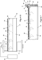
- a powered reel 12 on a spill response vessel 14 carries an inflatable boom 50 in accordance with the invention.
- the boom 50 has internal conical bulkheads 28 defining multiple chambers 30 for redundancy and hence high integrity.
- the boom 50 may also comprise a series of individually-replaceable sections like the sections 18 of the boom 10 shown in Figures 1 to 4 ; however, the boom 50 is shown in Figures 5 to 7 as a single length for simplicity.
- the boom 50 again provides for single-point inflation of the chambers 30 via respective non-return filling valves 42 communicating with a common inflation cuff 38 extending along the boom 50, but in a different way to inflation of the prior art boom 10 as will be explained.
- the invention provides for easier, safer and more rapid deflation of the chambers 30 when the boom 50 is being recovered after deployment.
- a notable difference, and advantage, of the boom 50 over the prior art boom 10 is that only one vessel 14 is required to deploy the boom 50. Consequently, it is not necessary to use the towing vessel 16 of the prior art shown in Figure 1 to pull the boom 50 off the reel 12. This greatly simplifies the deployment operation by removing the complication of co-ordinating the movements of two vessels 14, 16 as in the prior art. As a result, the speed and safety of deployment are improved because there are fewer operations to go wrong.
- the boom 50 of the invention is deployed by launching a sea anchor 52 at the free end of the boom 50 into the water, either as the vessel 14 moves forward through the water or as the vessel 14 is moored at a stationary position in a current of water.
- the sea anchor 52 acts as a drogue to create drag upon movement relative to the water and so applies tension to the boom 50.
- This tension pulls the boom 50 aft to deploy into the water, with increasing separation between the vessel 14 and the sea anchor 52, as the boom 50 is inflated while the reel 12 turns.
- an operator begins to rotate the reel 12 at a slow speed and the force exerted on the free end of the boom 50 by the sea anchor 52 begins to pull the boom 50 off the reel 12.
- the same operator can then begin to inflate the boom 50 by turning on a supply of compressed air, as will be explained.
- deployment of the boom 50 may be initiated and may proceed even while the vessel 14 is travelling at speed to the scene of a spill.
- the vessel 14 then tows the partially- or fully-deployed boom 50 directly to where it will be needed.
- the boom 50 can be in the water ready to do its job as quickly as possible on arrival of the vessel 14 at the scene.
- inflation of the boom 50 may be controlled by the operator who also controls the reel 12, in principle this allows a single operator to deploy the boom 50. This means that the operator of the reel 12 can undertake inflation of the boom 10 independently, without interaction with other operators, and can deploy the boom 10 at a rate to suit its rate of inflation.
- Air to inflate the boom 50 is supplied from a compressed air source 54 on board the vessel 14, such as an air compressor and/or a bank of high-pressure air cylinders.
- the compressed air source 54 supplies air at high pressure to a rotary swivel coupling 56 on the reel 12 so that the high-pressure air is available continuously to the boom 50 as the reel 12 rotates.
- the reel 12 contains a duct 58 to receive the high-pressure air from the rotary swivel coupling 56 and to deliver that air into a high-pressure air line 60 that extends along substantially the full length of the boom 50, from the reel end to the free end of the boom 50.
- the high-pressure air line 60 can be uncoupled from the duct 58 to remove the boom 50 from the reel 12 on completion of deployment.
- the high-pressure air line 60 is notably narrower than the inflation cuff 38, which conveys a much larger volume of air at lower pressure than in the air line 60.
- the high-pressure air line 60 is shown in Figures 6 and 7 attached externally to the inflation cuff 38 of the boom 50 for ease of illustration. However, the high-pressure air line 60 can be attached to or incorporated in any part of the boom 50, either externally or internally.
- the high-pressure air line 60 communicates with a buoyant inflation post 62 at the free end of the boom 50.
- the inflation post 62 with the attached free end of the boom 50 is deployed over the stern of the vessel 14 immediately after the sea anchor 52.
- the inflation post 62 has a buoyant upper end 64, for example of solid foamed plastics, and a ballasted lower end 66, for example containing an iron weight. This is to ensure that the inflation post 62 floats substantially upright in the water with the upper end 64 protruding well above the water surface.
- a generally-tubular airflow amplifier 68 positioned in the upper end of the inflation post 62 receives high-pressure air from the high-pressure air line 60.
- the high-pressure air enters the airflow amplifier 68 through a high-pressure air inlet 70 positioned between an airflow intake 72 and an airflow outlet 74 of the airflow amplifier 68.
- the airflow intake 72 draws in atmospheric air from above the water surface.
- the airflow outlet 74 exhausts that air, plus air entering through the high-pressure air inlet 70, as a high volume, high-velocity flow that enters the inflation cuff 38 to inflate the chambers 30 via the filling valves 42.
- the airflow amplifier 68 (known variously in the art of pneumatics as a vacuum pump, an air accelerator or an air amplifier) works by directing the incoming high-pressure air from the high-pressure air inlet 70 around an internal annular chamber 76.
- the high-pressure air in the annular chamber 76 is then throttled through a ring nozzle 78 to form an annular high-velocity primary airstream within the airflow amplifier 68.
- the primary air stream adheres to an annular outwardly-tapering venturi-shaped coanda profile 80 on the radially inner side of the airflow amplifier 68, which directs the primary airstream toward the airflow outlet 74.
- a low-pressure region is created at the centre of the annular primary air stream, which region extends between the airflow intake 72 and the ring nozzle 78.
- the low pressure in the airflow intake 72 draws in a high-volume flow of surrounding atmospheric air, which is entrained into the primary air stream.
- airflow amplifiers or air accelerators within the inventive concept, such as those that utilise an annular array of discrete nozzles. Such nozzles are arranged to produce an annular high-velocity air stream. The effect is similar to the ring-nozzle type described above.
- the key benefit of the airflow amplifier 68 is that a comparatively low-volume air flow at high pressure generates a pressure difference that moves a much larger volume of air to inflate the chambers 30.
- the volume of air leaving the airflow amplifier 68 in the exhaust flow through the airflow outlet 74 is far in excess of the volume of compressed air supplied into the high-pressure air inlet 70.
- the majority of the air in the exhaust flow does not come from the high-pressure air line 60 but instead is atmospheric air that enters the airflow intake 72. In this way, a high volume of atmospheric air is used for inflation of the boom 50 even though a much smaller volume of high-pressure air is supplied from the spill response vessel 14.
- compressed air from the high-pressure air line 60 is expanded in the airflow amplifier 68 to draw a much larger volume of air into the airflow intake 72.
- the expanded air combines with the larger volume of drawn-in air to direct a high-volume, relatively low pressure (but still above ambient pressure) flow of air from the airflow outlet 74 into the inflation cuff 38 and from there into the chambers 30 through the respective filling valves 42.
- compressed air in the high-pressure air line 60 may be at a gauge pressure of about 6 to 10 bar.
- Air exhausting from the airflow outlet 74 of the airflow amplifier 68 used for inflation of the boom 50 may be at a gauge pressure of up to about 103mbar (1.5psi) with a typical flow rate of about 6m 3 /hr, representing airflow multiplication of 4x to 5x.
- the airflow amplifier 68 shown in Figure 8 has the optional feature of an internally-threaded tubular body 82 engaged with an externally threaded tubular insert 84 that defines the outwardly-tapering venturi-shaped coanda profile 80.
- the annular opening of the ring nozzle 78 can be adjusted, if required, by turning the insert 84 within the body 82 as shown to move the insert 84 axially with respect to the body 82. This allows the airflow characteristics of the airflow amplifier 68 to be adjusted if needs be.
- the buoyancy of the inflation post 62 prevents the free end of the boom 50 sinking in the water in the event of incomplete inflation and so keeps the airflow intake 72 of the airflow amplifier 68 clear of the water to draw in atmospheric air. Nevertheless, provision may be made to trap and to drain away any water that may inadvertently enter the airflow intake 72, preferably before that water can enter the inflation cuff 38.
- the inflation post 62 Being at the free end of the boom 50, the inflation post 62 provides a convenient fixing point for the sea anchor 52, which is attached to the inflation post 62 by a bridle and rope 86.
- the inflation post 62 is attached, in turn, to the free end of the boom 50 by a boom connector plate 88.
- a blow-off valve 90 automatically limits the maximum air pressure that can be supplied by the airflow amplifier 68.
- the blow-off valve 90 is conveniently situated in the airflow channel between the airflow outlet 74 of the airflow amplifier 68 and the inflation cuff 38.
- each chamber 30 may be fitted with a respective blow-off valve, or for deflation valves 92 of each chamber 30 to have blow-off functionality.
- a deflation valve 92 is positioned toward the aft end of each chamber 30 with respect to the recovery direction, which is from right to left as illustrated. Thus, when the boom 50 is being wound onto the reel 12, the end of the chamber 30 with the deflation valve 92 is wound on last.
- the system of the invention is particularly suitable for operation in hazardous environments, in particular to contain and recover flammable pollutants. This is because the system may use hydraulic and pneumatic, and hence non-electrical, auxiliary power systems of the deploying vessel.
- the system of the invention lends itself to being retrofitted to existing inflatable booms, which may be adapted by the addition of an inflation post at the free end of the boom to feed atmospheric air into the inflation cuff, and a high-pressure air line extending along the boom to supply the inflation post.
Landscapes
- Engineering & Computer Science (AREA)
- General Engineering & Computer Science (AREA)
- Environmental & Geological Engineering (AREA)
- Mechanical Engineering (AREA)
- Civil Engineering (AREA)
- Structural Engineering (AREA)
- Jet Pumps And Other Pumps (AREA)
Claims (16)
- Länglicher aufblasbarer Ausleger (50), Folgendes umfassend:eine Längsreihe von Kammern (30);einen Luftkanal (38), der sich entlang des Auslegers (50) erstreckt, um mit den Kammern (30) in Verbindung zu stehen; undein Luftgebläse (68), dadurch gekennzeichnet, dass es ferner eine Stromleitung (60) umfasst, die sich entlang des Auslegers (50) zum Luftgebläse (68) erstreckt, wobei das Luftgebläse (68) Folgendes aufweist:einen Luftstromeinlass (72) zum Ansaugen von atmosphärischer Luft, wenn dem Luftgebläse (68) entlang der verwendeten Stromleitung (60) Strom zugeführt wird; undeinen Luftstromauslass (74), der mit dem Luftkanal (38) in Verbindung steht, um die angesaugte Luft in den Luftkanal (38) abzugeben, um die Kammern (30) aufzublasen.
- Ausleger (50) nach Anspruch 1, wobei das Luftgebläse (68) ein Luftstromverstärker und die Stromleitung (60) eine Hochdruck-Luftleitung ist, die sich entlang des Auslegers (50) bis zu einem Hochdruck-Lufteinlass (70) des Luftstromverstärkers erstreckt, sodass atmosphärische Luft in den Luftstromeinlass (72) des Luftstromverstärkers eingesaugt wird, wenn Hochdruckluft durch die Hochdruck-Luftleitung zu dem verwendeten Hochdruck-Lufteinlass (70) zugeführt wird.
- Ausleger (50) nach Anspruch 1 oder Anspruch 2, wobei das Luftgebläse (68) angrenzend an ein erstes Ende des Auslegers (50) angeordnet ist und der Luftkanal (38) und die Stromleitung (60) sich im Wesentlichen über eine gesamte Länge des Auslegers (50) erstrecken.
- Ausleger nach Anspruch 3, wobei sich die Stromleitung (60) von dem Luftgebläse (68) zu einer Kupplung erstreckt, die an ein zweites Ende des Auslegers angrenzt, das dem ersten Ende gegenüberliegt, um an eine Energiequelle (54) angeschlossen zu werden.
- Ausleger (50) nach einem vorhergehenden Anspruch, wobei das Luftgebläse (68) von einem Schwimmkörper (62) gestützt wird, der an dem Ausleger (50) befestigt ist.
- Ausleger (50) nach Anspruch 5, wobei der Schwimmkörper (62) angeordnet ist, um den Luftstromeinlass (72) des Luftgebläses (68) über Wasser zu halten, in dem der Schwimmkörper (62) bei der Benutzung schwimmt.
- Der Ausleger (50) eines vorhergehenden Anspruchs, der so angeordnet ist, dass die Leistung in der Stromleitung (60) in einer ersten Richtung entlang des Auslegers (50) und die angesaugte Luftströmung in dem Luftkanal (38) in einer zweiten Richtung entlang des Auslegers (50) entgegen der ersten Richtung fließt.
- In Kombination mit dem Ausleger (50) eines vorhergehenden Anspruchs und einer Rolle (12), um die der Ausleger (50) gewickelt ist, wobei das Luftgebläse (68) angrenzend an ein freies, von der Rolle (12) entferntes Ende des Auslegers (50) angeordnet ist.
- Kombination nach Anspruch 8, wobei die Rolle (12) eine drehbare Kraftkupplung (56) zwischen einer Energiequelle (54) und der Stromleitung (60) des Auslegers (50) umfasst.
- Schiff (14), das den Ausleger (50) nach einem der Ansprüche 1 bis 7 und/oder die Kombination aus dem Ausleger (50) und der Rolle (12) nach Anspruch 8 oder 9 trägt.
- Verfahren zum Aufblasen einer Längsreihe von Kammern (30) in einem länglichen Ausleger (50), wobei das Verfahren Folgendes umfasst:
Zuführen von Energie entlang des Auslegers (50) in einer ersten Richtung, um ein Luftgebläse (68) anzutreiben, das atmosphärische Luft ansaugt und die angesaugte Luft abgibt, um in eine zweite Richtung entlang des Auslegers (50) zu strömen, die der ersten Richtung entgegengesetzt ist, um die Kammern (30) aufzublasen. - Verfahren nach Anspruch 11, umfassend das Einsetzen des Auslegers (50) in ein Gewässer in der ersten Richtung.
- Verfahren nach Anspruch 12, umfassend das Aufblasen der Kammern (30) während der Inbetriebnahme des Auslegers (50).
- Verfahren nach Anspruch 12 oder Anspruch 13, umfassend das Entfalten des Auslegers (50) von einer Rolle (12) aus, die von einem Schiff (14) getragen wird, das auf dem Gewässer schwimmt, und/oder umfassend das Zuführen der Energie durch die Rolle (12).
- Verfahren nach einem der Ansprüche 12 bis 14, umfassend das Schwimmen des Luftgebläses (68) auf dem Gewässer.
- Verfahren nach einem der Ansprüche 11 bis 15, wobei das Luftgebläse (68) ein Luftstromverstärker ist und die Leistung als Hochdruckluftstrom einem Hochdruck-Lufteinlass (70) des Luftstromverstärkers zugeführt wird, sodass atmosphärische Luft in den Luftstromeinlass (72) des Luftstromverstärkers eingesaugt wird, wenn Hochdruckluft dem verwendeten Hochdruck-Lufteinlass (70) zugeführt wird.
Applications Claiming Priority (2)
| Application Number | Priority Date | Filing Date | Title |
|---|---|---|---|
| GB1603213.8A GB2547667B (en) | 2016-02-24 | 2016-02-24 | Inflatable booms |
| PCT/GB2017/050476 WO2017144888A1 (en) | 2016-02-24 | 2017-02-23 | Inflatable booms |
Publications (2)
| Publication Number | Publication Date |
|---|---|
| EP3420141A1 EP3420141A1 (de) | 2019-01-02 |
| EP3420141B1 true EP3420141B1 (de) | 2020-04-08 |
Family
ID=55753127
Family Applications (1)
| Application Number | Title | Priority Date | Filing Date |
|---|---|---|---|
| EP17711734.8A Active EP3420141B1 (de) | 2016-02-24 | 2017-02-23 | Aufblasbare ausleger |
Country Status (4)
| Country | Link |
|---|---|
| EP (1) | EP3420141B1 (de) |
| DK (1) | DK3420141T3 (de) |
| GB (1) | GB2547667B (de) |
| WO (1) | WO2017144888A1 (de) |
Families Citing this family (3)
| Publication number | Priority date | Publication date | Assignee | Title |
|---|---|---|---|---|
| CN108265687B (zh) * | 2018-03-26 | 2023-05-26 | 扬州三江环安设备有限公司 | 一种快速收放式围油栏 |
| CN110424348A (zh) * | 2019-08-12 | 2019-11-08 | 浙江海洋大学 | 自动航行自动回收的电动式围油栏及其作业方法 |
| ES2758823A1 (es) * | 2020-01-20 | 2020-05-06 | Blue And Green Env Solutions Sl | Dispositivo para limpieza de agua del mar |
Family Cites Families (11)
| Publication number | Priority date | Publication date | Assignee | Title |
|---|---|---|---|---|
| US3631679A (en) * | 1969-07-24 | 1972-01-04 | Paul Fisch | Apparatus to confine and recover oil spillage at sea |
| GB1284418A (en) * | 1969-10-13 | 1972-08-09 | British Petroleum Co | Inflator |
| WO1992009750A1 (en) * | 1990-11-29 | 1992-06-11 | Willis Richard R | Floating contaminant containment systems |
| US5806572A (en) * | 1996-03-06 | 1998-09-15 | Voller; Ronald L. | Apparatus for inflating and deflating a dunnage bag |
| US7610929B2 (en) * | 2002-05-20 | 2009-11-03 | Illinois Tool Works Inc. | Air bag inflation/ deflation system |
| US7320347B2 (en) * | 2003-10-14 | 2008-01-22 | Sunrise Arkansas, Inc. | Inflation and deflation apparatus |
| US8251612B2 (en) * | 2009-08-14 | 2012-08-28 | Skidmore, Owings & Merrill Llp | Tidal responsive barrier |
| US9206575B2 (en) * | 2010-06-25 | 2015-12-08 | Michael T. D. Miller | Onboard oil containment system |
| US9512585B1 (en) * | 2010-10-12 | 2016-12-06 | Michael T Miller | On-board re-inflatable containment boom system and method |
| CA2870384C (en) * | 2012-04-15 | 2020-11-03 | Harbo Technologies Ltd. | Rapid-deployment oil spill containment boom and method of deployment |
| FR3019195B1 (fr) * | 2014-04-01 | 2016-04-15 | Musthane | Barrage gonflable flottant |
-
2016
- 2016-02-24 GB GB1603213.8A patent/GB2547667B/en active Active
-
2017
- 2017-02-23 DK DK17711734.8T patent/DK3420141T3/da active
- 2017-02-23 EP EP17711734.8A patent/EP3420141B1/de active Active
- 2017-02-23 WO PCT/GB2017/050476 patent/WO2017144888A1/en not_active Ceased
Non-Patent Citations (1)
| Title |
|---|
| None * |
Also Published As
| Publication number | Publication date |
|---|---|
| GB201603213D0 (en) | 2016-04-06 |
| DK3420141T3 (da) | 2020-07-20 |
| WO2017144888A1 (en) | 2017-08-31 |
| EP3420141A1 (de) | 2019-01-02 |
| GB2547667A (en) | 2017-08-30 |
| GB2547667B (en) | 2018-10-03 |
Similar Documents
| Publication | Publication Date | Title |
|---|---|---|
| US20230143730A1 (en) | Onboard oil containment system | |
| US20050016372A1 (en) | Vessel immobiliser projectile | |
| US4123911A (en) | Oil control system | |
| EP3420141B1 (de) | Aufblasbare ausleger | |
| US7509920B2 (en) | Inflatable fender system and method | |
| US5372455A (en) | Oil spill containment system | |
| US9809942B2 (en) | On-board re-inflatable containment boom and control system | |
| US9475556B1 (en) | System for refloating grounded vessels | |
| US20180016762A1 (en) | On-board spool-able re-useable containment boom and control system | |
| EP3303709B1 (de) | Bordeigenes wiederaufblasbares eindämmungsauslegersystem und -verfahren | |
| US20060048665A1 (en) | Inflatable member projectile | |
| CN115447723A (zh) | 一种防止空投艇着水倾覆的装置及其防倾覆方法 | |
| JPH0640384A (ja) | 水中浮遊物の回収装置 | |
| JPH05310179A (ja) | 水中浮遊物の回収装置 | |
| JPH05310180A (ja) | 水中浮遊物の回収装置 | |
| AU9039291A (en) | Oil spill containment system |
Legal Events
| Date | Code | Title | Description |
|---|---|---|---|
| STAA | Information on the status of an ep patent application or granted ep patent |
Free format text: STATUS: UNKNOWN |
|
| STAA | Information on the status of an ep patent application or granted ep patent |
Free format text: STATUS: THE INTERNATIONAL PUBLICATION HAS BEEN MADE |
|
| PUAI | Public reference made under article 153(3) epc to a published international application that has entered the european phase |
Free format text: ORIGINAL CODE: 0009012 |
|
| STAA | Information on the status of an ep patent application or granted ep patent |
Free format text: STATUS: REQUEST FOR EXAMINATION WAS MADE |
|
| 17P | Request for examination filed |
Effective date: 20180924 |
|
| AK | Designated contracting states |
Kind code of ref document: A1 Designated state(s): AL AT BE BG CH CY CZ DE DK EE ES FI FR GB GR HR HU IE IS IT LI LT LU LV MC MK MT NL NO PL PT RO RS SE SI SK SM TR |
|
| AX | Request for extension of the european patent |
Extension state: BA ME |
|
| DAV | Request for validation of the european patent (deleted) | ||
| DAX | Request for extension of the european patent (deleted) | ||
| GRAP | Despatch of communication of intention to grant a patent |
Free format text: ORIGINAL CODE: EPIDOSNIGR1 |
|
| STAA | Information on the status of an ep patent application or granted ep patent |
Free format text: STATUS: GRANT OF PATENT IS INTENDED |
|
| INTG | Intention to grant announced |
Effective date: 20190917 |
|
| GRAS | Grant fee paid |
Free format text: ORIGINAL CODE: EPIDOSNIGR3 |
|
| GRAA | (expected) grant |
Free format text: ORIGINAL CODE: 0009210 |
|
| STAA | Information on the status of an ep patent application or granted ep patent |
Free format text: STATUS: THE PATENT HAS BEEN GRANTED |
|
| AK | Designated contracting states |
Kind code of ref document: B1 Designated state(s): AL AT BE BG CH CY CZ DE DK EE ES FI FR GB GR HR HU IE IS IT LI LT LU LV MC MK MT NL NO PL PT RO RS SE SI SK SM TR |
|
| REG | Reference to a national code |
Ref country code: AT Ref legal event code: REF Ref document number: 1254549 Country of ref document: AT Kind code of ref document: T Effective date: 20200415 Ref country code: CH Ref legal event code: EP |
|
| REG | Reference to a national code |
Ref country code: DE Ref legal event code: R096 Ref document number: 602017014420 Country of ref document: DE |
|
| REG | Reference to a national code |
Ref country code: IE Ref legal event code: FG4D |
|
| REG | Reference to a national code |
Ref country code: FI Ref legal event code: FGE |
|
| REG | Reference to a national code |
Ref country code: DK Ref legal event code: T3 Effective date: 20200715 |
|
| REG | Reference to a national code |
Ref country code: NL Ref legal event code: MP Effective date: 20200408 |
|
| REG | Reference to a national code |
Ref country code: LT Ref legal event code: MG4D |
|
| PG25 | Lapsed in a contracting state [announced via postgrant information from national office to epo] |
Ref country code: PT Free format text: LAPSE BECAUSE OF FAILURE TO SUBMIT A TRANSLATION OF THE DESCRIPTION OR TO PAY THE FEE WITHIN THE PRESCRIBED TIME-LIMIT Effective date: 20200817 Ref country code: GR Free format text: LAPSE BECAUSE OF FAILURE TO SUBMIT A TRANSLATION OF THE DESCRIPTION OR TO PAY THE FEE WITHIN THE PRESCRIBED TIME-LIMIT Effective date: 20200709 Ref country code: SE Free format text: LAPSE BECAUSE OF FAILURE TO SUBMIT A TRANSLATION OF THE DESCRIPTION OR TO PAY THE FEE WITHIN THE PRESCRIBED TIME-LIMIT Effective date: 20200408 Ref country code: NL Free format text: LAPSE BECAUSE OF FAILURE TO SUBMIT A TRANSLATION OF THE DESCRIPTION OR TO PAY THE FEE WITHIN THE PRESCRIBED TIME-LIMIT Effective date: 20200408 Ref country code: NO Free format text: LAPSE BECAUSE OF FAILURE TO SUBMIT A TRANSLATION OF THE DESCRIPTION OR TO PAY THE FEE WITHIN THE PRESCRIBED TIME-LIMIT Effective date: 20200708 Ref country code: LT Free format text: LAPSE BECAUSE OF FAILURE TO SUBMIT A TRANSLATION OF THE DESCRIPTION OR TO PAY THE FEE WITHIN THE PRESCRIBED TIME-LIMIT Effective date: 20200408 Ref country code: IS Free format text: LAPSE BECAUSE OF FAILURE TO SUBMIT A TRANSLATION OF THE DESCRIPTION OR TO PAY THE FEE WITHIN THE PRESCRIBED TIME-LIMIT Effective date: 20200808 |
|
| REG | Reference to a national code |
Ref country code: AT Ref legal event code: MK05 Ref document number: 1254549 Country of ref document: AT Kind code of ref document: T Effective date: 20200408 |
|
| PG25 | Lapsed in a contracting state [announced via postgrant information from national office to epo] |
Ref country code: LV Free format text: LAPSE BECAUSE OF FAILURE TO SUBMIT A TRANSLATION OF THE DESCRIPTION OR TO PAY THE FEE WITHIN THE PRESCRIBED TIME-LIMIT Effective date: 20200408 Ref country code: RS Free format text: LAPSE BECAUSE OF FAILURE TO SUBMIT A TRANSLATION OF THE DESCRIPTION OR TO PAY THE FEE WITHIN THE PRESCRIBED TIME-LIMIT Effective date: 20200408 Ref country code: HR Free format text: LAPSE BECAUSE OF FAILURE TO SUBMIT A TRANSLATION OF THE DESCRIPTION OR TO PAY THE FEE WITHIN THE PRESCRIBED TIME-LIMIT Effective date: 20200408 Ref country code: BG Free format text: LAPSE BECAUSE OF FAILURE TO SUBMIT A TRANSLATION OF THE DESCRIPTION OR TO PAY THE FEE WITHIN THE PRESCRIBED TIME-LIMIT Effective date: 20200708 |
|
| PG25 | Lapsed in a contracting state [announced via postgrant information from national office to epo] |
Ref country code: AL Free format text: LAPSE BECAUSE OF FAILURE TO SUBMIT A TRANSLATION OF THE DESCRIPTION OR TO PAY THE FEE WITHIN THE PRESCRIBED TIME-LIMIT Effective date: 20200408 |
|
| REG | Reference to a national code |
Ref country code: DE Ref legal event code: R097 Ref document number: 602017014420 Country of ref document: DE |
|
| PG25 | Lapsed in a contracting state [announced via postgrant information from national office to epo] |
Ref country code: CZ Free format text: LAPSE BECAUSE OF FAILURE TO SUBMIT A TRANSLATION OF THE DESCRIPTION OR TO PAY THE FEE WITHIN THE PRESCRIBED TIME-LIMIT Effective date: 20200408 Ref country code: ES Free format text: LAPSE BECAUSE OF FAILURE TO SUBMIT A TRANSLATION OF THE DESCRIPTION OR TO PAY THE FEE WITHIN THE PRESCRIBED TIME-LIMIT Effective date: 20200408 Ref country code: AT Free format text: LAPSE BECAUSE OF FAILURE TO SUBMIT A TRANSLATION OF THE DESCRIPTION OR TO PAY THE FEE WITHIN THE PRESCRIBED TIME-LIMIT Effective date: 20200408 Ref country code: EE Free format text: LAPSE BECAUSE OF FAILURE TO SUBMIT A TRANSLATION OF THE DESCRIPTION OR TO PAY THE FEE WITHIN THE PRESCRIBED TIME-LIMIT Effective date: 20200408 Ref country code: IT Free format text: LAPSE BECAUSE OF FAILURE TO SUBMIT A TRANSLATION OF THE DESCRIPTION OR TO PAY THE FEE WITHIN THE PRESCRIBED TIME-LIMIT Effective date: 20200408 Ref country code: RO Free format text: LAPSE BECAUSE OF FAILURE TO SUBMIT A TRANSLATION OF THE DESCRIPTION OR TO PAY THE FEE WITHIN THE PRESCRIBED TIME-LIMIT Effective date: 20200408 Ref country code: SM Free format text: LAPSE BECAUSE OF FAILURE TO SUBMIT A TRANSLATION OF THE DESCRIPTION OR TO PAY THE FEE WITHIN THE PRESCRIBED TIME-LIMIT Effective date: 20200408 |
|
| PLBE | No opposition filed within time limit |
Free format text: ORIGINAL CODE: 0009261 |
|
| STAA | Information on the status of an ep patent application or granted ep patent |
Free format text: STATUS: NO OPPOSITION FILED WITHIN TIME LIMIT |
|
| PG25 | Lapsed in a contracting state [announced via postgrant information from national office to epo] |
Ref country code: SK Free format text: LAPSE BECAUSE OF FAILURE TO SUBMIT A TRANSLATION OF THE DESCRIPTION OR TO PAY THE FEE WITHIN THE PRESCRIBED TIME-LIMIT Effective date: 20200408 Ref country code: PL Free format text: LAPSE BECAUSE OF FAILURE TO SUBMIT A TRANSLATION OF THE DESCRIPTION OR TO PAY THE FEE WITHIN THE PRESCRIBED TIME-LIMIT Effective date: 20200408 |
|
| 26N | No opposition filed |
Effective date: 20210112 |
|
| PG25 | Lapsed in a contracting state [announced via postgrant information from national office to epo] |
Ref country code: SI Free format text: LAPSE BECAUSE OF FAILURE TO SUBMIT A TRANSLATION OF THE DESCRIPTION OR TO PAY THE FEE WITHIN THE PRESCRIBED TIME-LIMIT Effective date: 20200408 |
|
| REG | Reference to a national code |
Ref country code: DE Ref legal event code: R119 Ref document number: 602017014420 Country of ref document: DE |
|
| PG25 | Lapsed in a contracting state [announced via postgrant information from national office to epo] |
Ref country code: MC Free format text: LAPSE BECAUSE OF FAILURE TO SUBMIT A TRANSLATION OF THE DESCRIPTION OR TO PAY THE FEE WITHIN THE PRESCRIBED TIME-LIMIT Effective date: 20200408 |
|
| GBPC | Gb: european patent ceased through non-payment of renewal fee |
Effective date: 20210223 |
|
| REG | Reference to a national code |
Ref country code: BE Ref legal event code: MM Effective date: 20210228 |
|
| PG25 | Lapsed in a contracting state [announced via postgrant information from national office to epo] |
Ref country code: CH Free format text: LAPSE BECAUSE OF NON-PAYMENT OF DUE FEES Effective date: 20210228 Ref country code: LI Free format text: LAPSE BECAUSE OF NON-PAYMENT OF DUE FEES Effective date: 20210228 Ref country code: LU Free format text: LAPSE BECAUSE OF NON-PAYMENT OF DUE FEES Effective date: 20210223 |
|
| PG25 | Lapsed in a contracting state [announced via postgrant information from national office to epo] |
Ref country code: GB Free format text: LAPSE BECAUSE OF NON-PAYMENT OF DUE FEES Effective date: 20210223 Ref country code: FR Free format text: LAPSE BECAUSE OF NON-PAYMENT OF DUE FEES Effective date: 20210228 Ref country code: IE Free format text: LAPSE BECAUSE OF NON-PAYMENT OF DUE FEES Effective date: 20210223 Ref country code: DE Free format text: LAPSE BECAUSE OF NON-PAYMENT OF DUE FEES Effective date: 20210901 |
|
| PG25 | Lapsed in a contracting state [announced via postgrant information from national office to epo] |
Ref country code: BE Free format text: LAPSE BECAUSE OF NON-PAYMENT OF DUE FEES Effective date: 20210228 |
|
| PG25 | Lapsed in a contracting state [announced via postgrant information from national office to epo] |
Ref country code: CY Free format text: LAPSE BECAUSE OF FAILURE TO SUBMIT A TRANSLATION OF THE DESCRIPTION OR TO PAY THE FEE WITHIN THE PRESCRIBED TIME-LIMIT Effective date: 20200408 |
|
| PG25 | Lapsed in a contracting state [announced via postgrant information from national office to epo] |
Ref country code: HU Free format text: LAPSE BECAUSE OF FAILURE TO SUBMIT A TRANSLATION OF THE DESCRIPTION OR TO PAY THE FEE WITHIN THE PRESCRIBED TIME-LIMIT; INVALID AB INITIO Effective date: 20170223 |
|
| PG25 | Lapsed in a contracting state [announced via postgrant information from national office to epo] |
Ref country code: MK Free format text: LAPSE BECAUSE OF FAILURE TO SUBMIT A TRANSLATION OF THE DESCRIPTION OR TO PAY THE FEE WITHIN THE PRESCRIBED TIME-LIMIT Effective date: 20200408 |
|
| PG25 | Lapsed in a contracting state [announced via postgrant information from national office to epo] |
Ref country code: MT Free format text: LAPSE BECAUSE OF FAILURE TO SUBMIT A TRANSLATION OF THE DESCRIPTION OR TO PAY THE FEE WITHIN THE PRESCRIBED TIME-LIMIT Effective date: 20200408 |
|
| PG25 | Lapsed in a contracting state [announced via postgrant information from national office to epo] |
Ref country code: TR Free format text: LAPSE BECAUSE OF FAILURE TO SUBMIT A TRANSLATION OF THE DESCRIPTION OR TO PAY THE FEE WITHIN THE PRESCRIBED TIME-LIMIT Effective date: 20200408 |
|
| PGFP | Annual fee paid to national office [announced via postgrant information from national office to epo] |
Ref country code: DK Payment date: 20260223 Year of fee payment: 10 |
|
| PGFP | Annual fee paid to national office [announced via postgrant information from national office to epo] |
Ref country code: FI Payment date: 20260220 Year of fee payment: 10 |