EP3418531A1 - Fixed vane turbo charger - Google Patents
Fixed vane turbo charger Download PDFInfo
- Publication number
- EP3418531A1 EP3418531A1 EP16896866.7A EP16896866A EP3418531A1 EP 3418531 A1 EP3418531 A1 EP 3418531A1 EP 16896866 A EP16896866 A EP 16896866A EP 3418531 A1 EP3418531 A1 EP 3418531A1
- Authority
- EP
- European Patent Office
- Prior art keywords
- vane
- fixed vane
- fixed
- impeller
- flow passage
- Prior art date
- Legal status (The legal status is an assumption and is not a legal conclusion. Google has not performed a legal analysis and makes no representation as to the accuracy of the status listed.)
- Granted
Links
Images





Classifications
-
- F—MECHANICAL ENGINEERING; LIGHTING; HEATING; WEAPONS; BLASTING
- F01—MACHINES OR ENGINES IN GENERAL; ENGINE PLANTS IN GENERAL; STEAM ENGINES
- F01D—NON-POSITIVE DISPLACEMENT MACHINES OR ENGINES, e.g. STEAM TURBINES
- F01D9/00—Stators
- F01D9/02—Nozzles; Nozzle boxes; Stator blades; Guide conduits, e.g. individual nozzles
- F01D9/04—Nozzles; Nozzle boxes; Stator blades; Guide conduits, e.g. individual nozzles forming ring or sector
- F01D9/045—Nozzles; Nozzle boxes; Stator blades; Guide conduits, e.g. individual nozzles forming ring or sector for radial flow machines or engines
-
- F—MECHANICAL ENGINEERING; LIGHTING; HEATING; WEAPONS; BLASTING
- F01—MACHINES OR ENGINES IN GENERAL; ENGINE PLANTS IN GENERAL; STEAM ENGINES
- F01D—NON-POSITIVE DISPLACEMENT MACHINES OR ENGINES, e.g. STEAM TURBINES
- F01D9/00—Stators
- F01D9/02—Nozzles; Nozzle boxes; Stator blades; Guide conduits, e.g. individual nozzles
- F01D9/04—Nozzles; Nozzle boxes; Stator blades; Guide conduits, e.g. individual nozzles forming ring or sector
-
- F—MECHANICAL ENGINEERING; LIGHTING; HEATING; WEAPONS; BLASTING
- F02—COMBUSTION ENGINES; HOT-GAS OR COMBUSTION-PRODUCT ENGINE PLANTS
- F02B—INTERNAL-COMBUSTION PISTON ENGINES; COMBUSTION ENGINES IN GENERAL
- F02B37/00—Engines characterised by provision of pumps driven at least for part of the time by exhaust
- F02B37/12—Control of the pumps
- F02B37/22—Control of the pumps by varying cross-section of exhaust passages or air passages, e.g. by throttling turbine inlets or outlets or by varying effective number of guide conduits
-
- F—MECHANICAL ENGINEERING; LIGHTING; HEATING; WEAPONS; BLASTING
- F02—COMBUSTION ENGINES; HOT-GAS OR COMBUSTION-PRODUCT ENGINE PLANTS
- F02B—INTERNAL-COMBUSTION PISTON ENGINES; COMBUSTION ENGINES IN GENERAL
- F02B39/00—Component parts, details, or accessories relating to, driven charging or scavenging pumps, not provided for in groups F02B33/00 - F02B37/00
-
- F—MECHANICAL ENGINEERING; LIGHTING; HEATING; WEAPONS; BLASTING
- F01—MACHINES OR ENGINES IN GENERAL; ENGINE PLANTS IN GENERAL; STEAM ENGINES
- F01D—NON-POSITIVE DISPLACEMENT MACHINES OR ENGINES, e.g. STEAM TURBINES
- F01D9/00—Stators
- F01D9/02—Nozzles; Nozzle boxes; Stator blades; Guide conduits, e.g. individual nozzles
- F01D9/04—Nozzles; Nozzle boxes; Stator blades; Guide conduits, e.g. individual nozzles forming ring or sector
- F01D9/048—Nozzles; Nozzle boxes; Stator blades; Guide conduits, e.g. individual nozzles forming ring or sector for radial admission
-
- F—MECHANICAL ENGINEERING; LIGHTING; HEATING; WEAPONS; BLASTING
- F05—INDEXING SCHEMES RELATING TO ENGINES OR PUMPS IN VARIOUS SUBCLASSES OF CLASSES F01-F04
- F05D—INDEXING SCHEME FOR ASPECTS RELATING TO NON-POSITIVE-DISPLACEMENT MACHINES OR ENGINES, GAS-TURBINES OR JET-PROPULSION PLANTS
- F05D2220/00—Application
- F05D2220/40—Application in turbochargers
-
- F—MECHANICAL ENGINEERING; LIGHTING; HEATING; WEAPONS; BLASTING
- F05—INDEXING SCHEMES RELATING TO ENGINES OR PUMPS IN VARIOUS SUBCLASSES OF CLASSES F01-F04
- F05D—INDEXING SCHEME FOR ASPECTS RELATING TO NON-POSITIVE-DISPLACEMENT MACHINES OR ENGINES, GAS-TURBINES OR JET-PROPULSION PLANTS
- F05D2230/00—Manufacture
- F05D2230/50—Building or constructing in particular ways
- F05D2230/54—Building or constructing in particular ways by sheet metal manufacturing
-
- F—MECHANICAL ENGINEERING; LIGHTING; HEATING; WEAPONS; BLASTING
- F05—INDEXING SCHEMES RELATING TO ENGINES OR PUMPS IN VARIOUS SUBCLASSES OF CLASSES F01-F04
- F05D—INDEXING SCHEME FOR ASPECTS RELATING TO NON-POSITIVE-DISPLACEMENT MACHINES OR ENGINES, GAS-TURBINES OR JET-PROPULSION PLANTS
- F05D2250/00—Geometry
- F05D2250/10—Two-dimensional
- F05D2250/18—Two-dimensional patterned
- F05D2250/182—Two-dimensional patterned crenellated, notched
-
- F—MECHANICAL ENGINEERING; LIGHTING; HEATING; WEAPONS; BLASTING
- F05—INDEXING SCHEMES RELATING TO ENGINES OR PUMPS IN VARIOUS SUBCLASSES OF CLASSES F01-F04
- F05D—INDEXING SCHEME FOR ASPECTS RELATING TO NON-POSITIVE-DISPLACEMENT MACHINES OR ENGINES, GAS-TURBINES OR JET-PROPULSION PLANTS
- F05D2250/00—Geometry
- F05D2250/10—Two-dimensional
- F05D2250/18—Two-dimensional patterned
- F05D2250/183—Two-dimensional patterned zigzag
-
- F—MECHANICAL ENGINEERING; LIGHTING; HEATING; WEAPONS; BLASTING
- F05—INDEXING SCHEMES RELATING TO ENGINES OR PUMPS IN VARIOUS SUBCLASSES OF CLASSES F01-F04
- F05D—INDEXING SCHEME FOR ASPECTS RELATING TO NON-POSITIVE-DISPLACEMENT MACHINES OR ENGINES, GAS-TURBINES OR JET-PROPULSION PLANTS
- F05D2250/00—Geometry
- F05D2250/10—Two-dimensional
- F05D2250/18—Two-dimensional patterned
- F05D2250/184—Two-dimensional patterned sinusoidal
-
- Y—GENERAL TAGGING OF NEW TECHNOLOGICAL DEVELOPMENTS; GENERAL TAGGING OF CROSS-SECTIONAL TECHNOLOGIES SPANNING OVER SEVERAL SECTIONS OF THE IPC; TECHNICAL SUBJECTS COVERED BY FORMER USPC CROSS-REFERENCE ART COLLECTIONS [XRACs] AND DIGESTS
- Y02—TECHNOLOGIES OR APPLICATIONS FOR MITIGATION OR ADAPTATION AGAINST CLIMATE CHANGE
- Y02T—CLIMATE CHANGE MITIGATION TECHNOLOGIES RELATED TO TRANSPORTATION
- Y02T10/00—Road transport of goods or passengers
- Y02T10/10—Internal combustion engine [ICE] based vehicles
- Y02T10/12—Improving ICE efficiencies
Definitions
- the present disclosure relates to a fixed vane turbocharger.
- turbochargers are also reduced in size, and the production accuracy of each component has a greater influence on the performance of a turbocharger.
- an exhaust turbine of a turbocharger is provided with fixed vanes that do not rotate, disposed in a flow passage between a scroll flow passage and a turbine impeller, to rectify the flow of exhaust gas from the scroll flow passage to the turbine impeller and suppress variation of the performance (flow rate and efficiency).
- the fixed vanes of a turbocharger are casted.
- the fixed vanes tend to have a high surface roughness on the surfaces, which makes it difficult to improve the efficiency of the turbocharger.
- Patent Document 1 discloses a fixed vane turbocharger including fixed vanes formed by joining a plurality of plate members so as to intersect with one another.
- Patent Document 1 WO2011/042694A
- the fixed vanes disclosed in Patent Document 1 are formed by joining a plurality of plate members so as to intersect with one another, which makes the structure complex.
- the present invention was made in view of the above described typical problem, and an object of the present invention is to provide a fixed vane turbocharger whereby it is possible to achieve a high efficiency with a simple configuration.
- the phase of excitation of the rotor blades of the turbine impeller by the exhaust gas passing through the vane portions is displaced, which makes it possible to suppress an oscillation stress of the rotor blades. Furthermore, in a case where the fixed vane unit expands due to heat of exhaust gas, it is possible to absorb the displacement with bending of the vane portions, and thus it is possible to suppress occurrence of buckling in the vane portions.
- an expression of relative or absolute arrangement such as “in a direction”, “along a direction”, “parallel”, “orthogonal”, “centered”, “concentric” and “coaxial” shall not be construed as indicating only the arrangement in a strict literal sense, but also includes a state where the arrangement is relatively displaced by a tolerance, or by an angle or a distance whereby it is possible to achieve the same function.
- an expression of an equal state such as “same” “equal” and “uniform” shall not be construed as indicating only the state in which the feature is strictly equal, but also includes a state in which there is a tolerance or a difference that can still achieve the same function.
- an expression of a shape such as a rectangular shape or a cylindrical shape shall not be construed as only the geometrically strict shape, but also includes a shape with unevenness or chamfered corners within the range in which the same effect can be achieved.
- FIG. 1 is a schematic cross-sectional view of a fixed vane turbocharger 100 according to an embodiment of the present invention, taken along the rotational axis of the turbocharger 100.
- the fixed vane turbocharger 100 includes a turbine impeller 2 disposed coaxially with a non-depicted compressor, a housing 4, and at least one fixed vane unit 6.
- the axial direction of the turbine impeller 2 is referred to as merely “axial direction”
- the radial direction of the turbine impeller 2 is referred to as merely “radial direction”
- the circumferential direction of the turbine impeller 2 is referred to as merely “circumferential direction”.
- the housing 4 includes, inside thereof, an impeller housing space 8 that accommodates the turbine impeller 2, a scroll flow passage 10 formed on the radially outer side of the turbine impeller 2, and a communication flow passage 12 which brings the impeller housing space 8 and the scroll flow passage 10 into communication.
- the fixed vane unit 6 is disposed in the communication flow passage 12, and is fixed by a device such as a bolt to a portion 4a on the inner side of the scroll flow passage 10 with respect to the radial direction of the housing 4.
- the fixed vane unit 6 is disposed inside the communication flow passage 12 so as not to extend in the scroll flow passage 10.
- exhaust gas flowing into a non-depicted engine to the scroll flow passage 10 flows from the scroll flow passage 10 to the communication flow passage 12, and is rectified by the fixed vane unit 6 disposed in the communication flow passage 12, before being supplied to rotor blades 2a of the turbine impeller 2.
- FIG. 2 is a schematic perspective view schematically illustrating a part of a fixed vane unit 6 (6A) according to an embodiment.
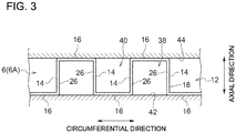
- FIG. 3 is a schematic diagram of an example of the shape of a trailing edge 26 of a vane portion 14 of the fixed vane unit 6 (6A).
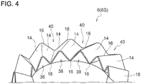
- FIG. 4 is a schematic perspective view schematically illustrating a part of a fixed vane unit 6 (6B) according to an embodiment.
- FIG. 5 is a schematic diagram of an example of the shape of a trailing edge 26 of a vane portion 14 of the fixed vane unit 6 (6B).
- FIG. 6 is a schematic diagram of an example of the shape of a trailing edge 26 of a vane portion 14 of the fixed vane unit 6 (6B).
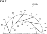
- FIG. 7 is a cross-sectional view of the fixed vane unit 6 (6A) taken along line A-A (see FIG. 1 ), that is, a schematic cross-sectional view schematically illustrating an example of a cross section orthogonal to the axial direction.
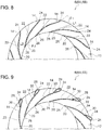
- FIG. 8 is a schematic diagram of an example of a cross section of the fixed vane unit 6 (6A, 6B), taken along line A-A.
- FIG. 9 is a schematic diagram of an example of a cross section of the fixed vane unit 6 (6A, 6B), taken along line A-A.
- each of the fixed vane units 6 (6A, 6B) includes at least two vane portions 14 and a coupling portion 16 coupling the two vane portions, and is formed by a single sheet metal member 18.
- the fixed vane unit 6 includes multiple (three or more) vane portions 14 and multiple (three or more) coupling portions 16, and the vane portions 14 and the coupling portion 16 are arranged alternately in the circumferential direction.
- the fixed vane unit 6 (6A) depicted in FIG. 2 has a shape formed by bending the single sheet metal member 18 into a rectangular corrugated shape (see FIG. 3 ) periodically
- the fixed vane unit 6 (6B) depicted in FIG. 4 has a shape formed by curving the single sheet metal member 18 into a triangular wave shape (see FIG. 5 ) or a sine wave shape (see FIG. 6 ) periodically.
- the fixed vane unit 6 (6A, 6B) is configured to divide the communication flow passage 12 so that hub-side flow passages 38 and shroud-side flow passages 40 are positioned alternately in the circumferential direction.
- Each of the hub-side flow passages 38 is defined by two vane portions 14, a coupling portion 16 coupling the two vane portions 14, and a hub-side wall 42 of the communication flow passage 12.
- Each of the shroud-side flow passages 40 is defined by two vane portions 14, a coupling portion 16 coupling the two vane portions 14, and a shroud-side wall 44 of the communication flow passage 12.
- each of the fixed vane units 6 is formed by a single sheet metal member 18, and thus it is possible to improve the surface roughness and reduce costs of the fixed vane units 6, compared to a case where each fixed vane unit 6 is formed by casting.
- the at least two vane portions 14 are coupled via the coupling portion 16, and thus it is possible to increase the section modulus of the fixed vane unit 6 and suppress deformation and collapse due to the hydrodynamic force.
- the fixed vane unit 6 (6A, 6B) is formed by a single sheet metal member 18 over the entire periphery in the circumferential direction.
- the trailing edge 26 of the vane portion 14 extends parallel to the axial direction. In some embodiments, as shown in FIGs. 5 and 6 for instance, the trailing edge 26 of the vane portion 14 extends in a direction inclined toward the circumferential direction from the axial direction.
- the trailing edge 26 of the vane portion 14 extends in a direction inclined toward the circumferential direction from the axial direction, and thereby the phase of excitation of the rotor blades 2a of the turbine impeller 2 by the exhaust gas passing through the vane portions 14 is displaced, which makes it possible to suppress an oscillation stress of the rotor blades 2a. Furthermore, in a case where the fixed vane unit 6 expands due to heat of exhaust gas, it is possible to absorb the displacement with bending of the vane portion 14, and thus it is possible to suppress occurrence of buckling in the vane portion 14.
- the vane portions 14 extend linearly in a cross section orthogonal to the axial direction. With the above configuration, it is possible to simplify the configuration of the fixed vane units 6.
- At least the trailing-edge side portion 20 of the vane portion 14 is curved so as to be convex on the side of the pressure surface 22.
- the metal angle ⁇ 1 at the leading edge 24 of the vane portion 14 with respect to the tangent L1 in the circumferential direction is greater than the metal angle 82 at the trailing edge 26 of the vane portion 14 with respect to the tangent L2 in the circumferential direction.
- leading-edge side portion 28 of the vane portion 14 is rounded so as that the tip 30 of the leading-edge side portion 28 is positioned downstream of the leading edge 24 of the vane portion 14.
- leading-edge side portion 28 of the vane portion 14 is rounded as described above, and thereby it is possible to suppress loss due to collision of the leading edge 24 of the vane portion 14 of the fixed vane unit 6 with a flow flowing into the communication flow passage 12 from the scroll flow passage 10.
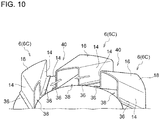
- FIG. 10 is a schematic perspective view schematically illustrating a part of a fixed vane unit 6 (6C) according to an embodiment.
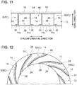
- FIG. 11 is a schematic diagram of an example of the shape of a trailing edge 26 of a vane portion 14 of the fixed vane unit 6 (6C).
- FIG. 12 is a cross-sectional view of the fixed vane unit 6 (6C) taken along line A-A (see FIG. 1 ), that is, a schematic cross-sectional view schematically illustrating an example of a cross section orthogonal to the axial direction.
- the fixed vane turbocharger 100 includes a plurality of fixed vane units 6 (6C) disposed at intervals in the circumferential direction.
- each of the fixed vane units 6 (6C) has a shape formed by bending the single sheet metal member 18 into a rectangular wave shape (see FIG. 3 ), and includes two vane portions 14, and one coupling portion 16 coupling the two vane portions 14.
- each of the two vane portions 14 has a leg portion 36.
- the leg portion 36 is disposed so as to protrude from an end portion of the vane portion 14 in the axial direction (in the depicted embodiment, the end portion of the vane portion 14 on the side of the hub-side wall 34 of the communication flow passage 12) toward the opposite side to the coupling portion 16, in the circumferential direction.
- the leg portion 36 is disposed along the flow passage wall (in the depicted embodiment, the hub-side wall 34) of the communication flow passage 12 from the leading edge 24 to the trailing edge 26 of the vane portion 14.
- a plurality of fixed vane units 6 are configured to divide the communication flow passage 12 so that hub-side flow passages 38 and shroud-side flow passages 40 are positioned alternately in the circumferential direction.
- Each of the hub-side flow passages 38 is defined by two vane portions 14, a coupling portion 16 coupling the two vane portions 14, and a hub-side wall 42 of the communication flow passage 12.
- Each of the shroud-side flow passages 40 is defined by two vane portions 14, two leg portions 36, a shroud-side wall 44 of the communication flow passage 12, and a hub-side wall 42 of the communication flow passage 12.
- each of the fixed vane units 6 (6C) is formed by a single sheet metal member 18, and thus it is possible to improve the surface roughness and reduce costs of the fixed vane units 6, compared to a case where each fixed vane unit 6 is formed by casting.
- the at least two vane portions 14 are coupled via the coupling portion 16, and thus it is possible to increase the section modulus of the fixed vane unit 6 and suppress deformation and collapse due to the hydrodynamic force.
- the fixed vane unit 6 is divided into a plurality of fixed vane units 6 (6C), and thus the fixed vane units 6 can be reduced in size while ensuring the structure strength, compared to the fixed vane unit 6 (6A, 6B) formed of a single sheet metal member 18 over the entire periphery in the circumferential direction.
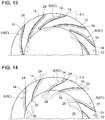
- the fixed vane units 6 (6C) may be installed so that the angle 83 between the chordwise direction of the vane portion 14 and the circumferential direction becomes small, as depicted in FIG. 13 .
- the fixed vane units 6 may be installed so that the angle 83 between the chordwise direction of the vane portion 14 and the circumferential direction becomes large, as depicted in FIG. 14 .
- the unnecessary part (dotted line in FIGs. 13 and 14 ) of the fixed vane unit 6 formed of sheet metal produced from a common mold may be cut apart to adjust the installment angle of the fixed vane units 6, which makes it possible to achieve a desired flow rate property with a simple configuration and low costs.
- each of the fixed vane units 6 (6C) includes two vane portions 14 and one coupling portion 16 coupling the two vane portions 14 in the embodiment shown in FIGs. 10 to 12
- fixed vane units each including three or more vane portions and two or more coupling portions may be disposed at intervals in the circumferential direction.
- the shape of the vane portion 14 described with reference to FIGs. 7 to 9 can be applied to the vane portion 14 of the fixed vane units 6 (6C) depicted in FIGs. 10 to 12 .
- the fixed vane turbocharger 100 may include a plurality of (stages of) fixed vane units 6 (6C) stacked in the axial direction.
- the fixed vane turbocharger 100 may include two fixed vane units 6 (6A) stacked in the axial direction.
- the two fixed vane units 6 (6A) are stacked in the axial direction such that the respective coupling portions 16 are in contact with each other.
- the fixed vane turbocharger 100 may include two fixed vane units 6 (6B) stacked in the axial direction.
- the two fixed vane units 6 (6A) are stacked in the axial direction such that the respective coupling portions 16 are in contact with each other.
- the fixed vane turbocharger 100 may include a fixed vane unit 6 (6A) and fixed vane unit 6 (6B) stacked in the axial direction.
- the fixed vane unit 6 (6A) and the fixed vane unit 6 (6B) are stacked in the axial direction such that the respective coupling portions 16 are in contact with each other.
- the present invention is also applicable to a diffuser blade of a compressor of a turbocharger.
- the fixed vane turbocharger includes a compressor impeller, a housing including, inside thereof, an impeller housing space which accommodates the compressor impeller, a scroll flow passage formed on the radially outer side of the compressor impeller, and a communication flow passage (diffuser flow passage) which brings the impeller housing space and the scroll flow passage into communication, an at least one fixed vane unit (diffuser vane unit) disposed in the communication flow passage and fixed to a portion on the inner side of the scroll flow passage in the radial direction of the compressor impeller in the housing.
- each of the fixed vane units includes at least two vane portions and a coupling portion coupling the two vane portions, and is formed by a single sheet metal member.
- each of the fixed vane units is formed by a single sheet metal member, and thus it is possible to improve the surface roughness and reduce costs of the fixed vane units 6, compared to a case where each fixed vane unit 6 is formed by casting. Thus, it is possible to enhance the rectifying effect of the fixed vane units, and improve the efficiency of the turbocharger with a simple configuration.
- the at least two vane portions are coupled via the coupling portion, and thus it is possible to increase the section modulus of the fixed vane unit and suppress deformation and collapse due to the hydrodynamic force.
Landscapes
- Engineering & Computer Science (AREA)
- Mechanical Engineering (AREA)
- General Engineering & Computer Science (AREA)
- Chemical & Material Sciences (AREA)
- Combustion & Propulsion (AREA)
- Supercharger (AREA)
Abstract
Description
- The present disclosure relates to a fixed vane turbocharger.
- In recent years, engines have been reduced in size thanks to forced supercharging, and a turbocharger is now also mounted to gasoline engines of a small exhaust amount. Thus, turbochargers are also reduced in size, and the production accuracy of each component has a greater influence on the performance of a turbocharger.
- In some cases, an exhaust turbine of a turbocharger is provided with fixed vanes that do not rotate, disposed in a flow passage between a scroll flow passage and a turbine impeller, to rectify the flow of exhaust gas from the scroll flow passage to the turbine impeller and suppress variation of the performance (flow rate and efficiency).
- Normally, the fixed vanes of a turbocharger are casted. Thus, the fixed vanes tend to have a high surface roughness on the surfaces, which makes it difficult to improve the efficiency of the turbocharger.
- Patent Document 1 discloses a fixed vane turbocharger including fixed vanes formed by joining a plurality of plate members so as to intersect with one another.
- Patent Document 1:
WO2011/042694A - With the fixed vane turbocharger disclosed in Patent Document 1, it is possible to reduce the surface roughness of the plate members easily, and thus further improvement of the efficiency of the turbocharger can be expected by providing fixed vanes having a smaller surface roughness compared to casted fixed vanes.
- However, the fixed vanes disclosed in Patent Document 1 are formed by joining a plurality of plate members so as to intersect with one another, which makes the structure complex.
- The present invention was made in view of the above described typical problem, and an object of the present invention is to provide a fixed vane turbocharger whereby it is possible to achieve a high efficiency with a simple configuration.
-
- (1) According to at least one embodiment of the present invention, a fixed vane turbocharger includes: an impeller; a housing including, inside thereof, an impeller housing space which accommodates the impeller, a scroll flow passage formed on a radially outer side of the impeller, and a communication flow passage which brings the impeller housing space and the scroll flow passage into communication; and at least one fixed vane unit disposed in the communication flow passage and fixed to a portion of the housing on an inner side of the scroll flow passage with respect to a radial direction of the impeller. Each of the at least one fixed vane unit includes at least two vane portions and a coupling portion coupling the two vane portions, and is formed of a single sheet metal member.
With the above fixed vane turbocharger (1), each of the fixed vane units is formed by a single sheet metal member, and thus it is possible to improve the surface roughness and reduce costs of the fixed vane units, compared to a case where each fixed vane unit is formed by casting. Thus, it is possible to enhance the rectifying effect of the fixed vane units, and improve the efficiency of the turbocharger with a simple configuration. Furthermore, the at least two vane portions are coupled via the coupling portion, and thus it is possible to increase the section modulus of the fixed vane units and suppress deformation and collapse due to the hydrodynamic force. - (2) In some embodiments, in the above fixed vane turbocharger (1), the at least one fixed vane unit is formed by the single sheet metal member over an entire periphery in a circumferential direction of the impeller.
With the above fixed vane turbocharger (2), it is possible to enhance the rigidity of the fixed vane unit as a whole. Further, an inward hydrodynamic force in the radial direction is offset, and thus it is possible to fix the fixed vane unit to the housing with a smaller fixing force (e.g. if the fixed vane unit is fastened by bolt fastening, a smaller fastening force). - (3) In some embodiments, in the above fixed vane turbocharger (1), the at least one fixed vane unit includes a plurality of fixed vane units disposed at intervals in a circumferential direction.
According to the fixed vane turbocharger (3), the fixed vane unit is divided into a plurality of fixed vane units, and thus the fixed vane units can be reduced in size while ensuring the structure strength, compared to a case where the fixed vane unit is formed of a single sheet metal member over the entire periphery in the circumferential direction.
Further, it is possible to adjust the installment angle of the fixed vane units when installing the fixed vane units, and thus it is possible to achieve flow rate characteristics corresponding to the installment angle of the fixed vane units. For instance, to address a small flow rate, the fixed vane units may be installed so that the angle between the chordwise direction of the vane portions and the circumferential direction becomes small. Further, to address a high flow rate, the fixed vane units may be installed so that the angle between the chordwise direction of the vane portions and the circumferential direction becomes large. Furthermore, the unnecessary part of the fixed vane unit formed of sheet metal produced from a common mold may be cut apart to adjust the installment angle of the fixed vane units, which makes it possible to achieve a desired flow rate property with a simple configuration and low costs. - (4) In some embodiments, in the fixed vane turbocharger according to any one of the above (1) to (3), the at least one fixed vane unit includes a plurality of fixed vane units stacked in an axial direction of the impeller.
With the above fixed vane turbocharger (4), the deformation amount in the axial direction per fixed vane unit decreases, and thus the manufacturability improves. Furthermore, it is possible to control the flow angle and the flow amount in the axial direction (height direction of the vane portion) of the impeller, and thus it is possible to improve the performance of the turbocharger. - (5) In some embodiments, in the fixed vane turbocharger according to any one of the above (1) to (4), at least a trailing-edge side portion of the vane portion is curved so as to be convex on a side of a pressure surface.
With the above fixed vane turbocharger (5), fluid strain near the trailing-edge side portion is suppressed, and thereby it is possible to improve the efficiency and enhance the reliability of the rotor blades of the turbine impeller (reduce an excitation force that excites the rotor blades). - (6) In some embodiments, in the fixed vane turbocharger according to any one of the above (1) to (5), a metal angle at a leading edge of the vane portion with respect to a tangent in a circumferential direction of the impeller is greater than a metal angle at a trailing edge of the vane portion with respect a tangent in the circumferential direction.
With the above fixed vane turbocharger (6), it is possible to suppress loss due to collision of the leading edge of the vane portion of the fixed vane unit with a flow flowing into the communication flow passage from the scroll flow passage. - (7) In some embodiments, in the above fixed vane turbocharger according to any one of the above (1) to (6), a leading-edge side portion of the vane portion is rounded so that a tip of the leading-edge side portion is positioned downstream of a leading edge of the vane portion.
According to the above description (7), the leading-edge side portion of the vane portion is rounded as described above, and thereby it is possible to suppress loss due to collision of the leading edge of the vane portion of the fixed vane unit with a flow flowing into the communication flow passage from the scroll flow passage. - (8) In some embodiments, in the fixed vane turbocharger according to any one of the above (1) to (7), a trailing edge of the vane portion extends in a direction inclined toward a circumferential direction from an axial direction of the impeller.
- With the above fixed vane turbocharger (8), the phase of excitation of the rotor blades of the turbine impeller by the exhaust gas passing through the vane portions is displaced, which makes it possible to suppress an oscillation stress of the rotor blades. Furthermore, in a case where the fixed vane unit expands due to heat of exhaust gas, it is possible to absorb the displacement with bending of the vane portions, and thus it is possible to suppress occurrence of buckling in the vane portions.
- According to at least one embodiment of the present invention, it is possible to provide a fixed vane turbocharger whereby it is possible to achieve a high efficiency through a simple configuration.
-
-
FIG. 1 is a schematic cross-sectional view of a fixedvane turbocharger 100 according to an embodiment of the present invention, taken along the rotational axis of theturbocharger 100. -
FIG. 2 is a schematic perspective view schematically illustrating a part of a fixed vane unit 6 (6A) according to an embodiment. -
FIG. 3 is a schematic diagram of an example of the shape of atrailing edge 26 of avane portion 14 of the fixed vane unit 6 (6A). -
FIG. 4 is a schematic perspective view schematically illustrating a part of a fixed vane unit 6 (6B) according to an embodiment. -
FIG. 5 is a schematic diagram of an example of the shape of atrailing edge 26 of avane portion 14 of the fixed vane unit 6 (6B). -
FIG. 6 is a schematic diagram of an example of the shape of atrailing edge 26 of avane portion 14 of the fixed vane unit 6 (6B). -
FIG. 7 is a cross-sectional view of the fixed vane unit 6 (6A, 6B) taken along line A-A (seeFIG. 1 ), that is, a schematic cross-sectional view schematically illustrating an example of a cross section orthogonal to the axial direction. -
FIG. 8 is a schematic diagram of an example of a cross section of the fixed vane unit 6 (6A, 6B), taken along line A-A. -
FIG. 9 is a schematic diagram of an example of a cross section of the fixed vane unit 6 (6A, 6B), taken along line A-A. -
FIG. 10 is a schematic perspective view schematically illustrating a part of a fixed vane unit 6 (6C) according to an embodiment. -
FIG. 11 is a schematic diagram of an example of the shape of atrailing edge 26 of avane portion 14 of the fixed vane unit 6 (6C). -
FIG. 12 is a cross-sectional view of the fixed vane unit 6 (6C) taken along line A-A (seeFIG. 1 ), that is, a schematic cross-sectional view schematically illustrating an example of a cross section orthogonal to the axial direction. -
FIG. 13 is a diagram for describing the installment angle of the fixed vane unit 6 (6C) corresponding to a small flow rate. -
FIG. 14 is a diagram for describing the installment angle of the fixed vane unit 6 (6C) corresponding to a high flow rate. -
FIG. 15 is a diagram of an example of a combination of two fixedvane units 6. -
FIG. 16 is a diagram of an example of a combination of two fixedvane units 6. -
FIG. 17 is a diagram of an example of a combination of two fixedvane units 6. -
FIG. 18 is a diagram of an example of a combination of two fixedvane units 6. -
FIG. 19 is a diagram of an example of a combination of two fixedvane units 6. - Embodiments of the present invention will now be described in detail with reference to the accompanying drawings. It is intended, however, that unless particularly identified, dimensions, materials, shapes, relative positions and the like of components described in the embodiments shall be interpreted as illustrative only and not intended to limit the scope of the present invention.
- For instance, an expression of relative or absolute arrangement such as "in a direction", "along a direction", "parallel", "orthogonal", "centered", "concentric" and "coaxial" shall not be construed as indicating only the arrangement in a strict literal sense, but also includes a state where the arrangement is relatively displaced by a tolerance, or by an angle or a distance whereby it is possible to achieve the same function.
- For instance, an expression of an equal state such as "same" "equal" and "uniform" shall not be construed as indicating only the state in which the feature is strictly equal, but also includes a state in which there is a tolerance or a difference that can still achieve the same function.
- Further, for instance, an expression of a shape such as a rectangular shape or a cylindrical shape shall not be construed as only the geometrically strict shape, but also includes a shape with unevenness or chamfered corners within the range in which the same effect can be achieved.
- On the other hand, an expression such as "comprise", "include", "have", "contain" and "constitute" are not intended to be exclusive of other components.
-
FIG. 1 is a schematic cross-sectional view of a fixedvane turbocharger 100 according to an embodiment of the present invention, taken along the rotational axis of theturbocharger 100. - The fixed
vane turbocharger 100 includes aturbine impeller 2 disposed coaxially with a non-depicted compressor, ahousing 4, and at least onefixed vane unit 6. - Hereinafter, unless otherwise stated, the axial direction of the
turbine impeller 2 is referred to as merely "axial direction", the radial direction of theturbine impeller 2 is referred to as merely "radial direction", and the circumferential direction of theturbine impeller 2 is referred to as merely "circumferential direction". - The
housing 4 includes, inside thereof, animpeller housing space 8 that accommodates theturbine impeller 2, ascroll flow passage 10 formed on the radially outer side of theturbine impeller 2, and acommunication flow passage 12 which brings theimpeller housing space 8 and thescroll flow passage 10 into communication. - The fixed
vane unit 6 is disposed in thecommunication flow passage 12, and is fixed by a device such as a bolt to aportion 4a on the inner side of thescroll flow passage 10 with respect to the radial direction of thehousing 4. The fixedvane unit 6 is disposed inside thecommunication flow passage 12 so as not to extend in thescroll flow passage 10. - In the embodiment shown in FIG.i, exhaust gas flowing into a non-depicted engine to the
scroll flow passage 10 flows from thescroll flow passage 10 to thecommunication flow passage 12, and is rectified by the fixedvane unit 6 disposed in thecommunication flow passage 12, before being supplied torotor blades 2a of theturbine impeller 2. -
FIG. 2 is a schematic perspective view schematically illustrating a part of a fixed vane unit 6 (6A) according to an embodiment.FIG. 3 is a schematic diagram of an example of the shape of a trailingedge 26 of avane portion 14 of the fixed vane unit 6 (6A).FIG. 4 is a schematic perspective view schematically illustrating a part of a fixed vane unit 6 (6B) according to an embodiment.FIG. 5 is a schematic diagram of an example of the shape of a trailingedge 26 of avane portion 14 of the fixed vane unit 6 (6B).FIG. 6 is a schematic diagram of an example of the shape of a trailingedge 26 of avane portion 14 of the fixed vane unit 6 (6B).FIG. 7 is a cross-sectional view of the fixed vane unit 6 (6A) taken along line A-A (seeFIG. 1 ), that is, a schematic cross-sectional view schematically illustrating an example of a cross section orthogonal to the axial direction.FIG. 8 is a schematic diagram of an example of a cross section of the fixed vane unit 6 (6A, 6B), taken along line A-A.FIG. 9 is a schematic diagram of an example of a cross section of the fixed vane unit 6 (6A, 6B), taken along line A-A. - In some embodiments, as shown in
FIGs. 2 to 6 for instance, each of the fixed vane units 6 (6A, 6B) includes at least twovane portions 14 and acoupling portion 16 coupling the two vane portions, and is formed by a singlesheet metal member 18. In an illustrative embodiment, the fixedvane unit 6 includes multiple (three or more)vane portions 14 and multiple (three or more)coupling portions 16, and thevane portions 14 and thecoupling portion 16 are arranged alternately in the circumferential direction. The fixed vane unit 6 (6A) depicted inFIG. 2 has a shape formed by bending the singlesheet metal member 18 into a rectangular corrugated shape (seeFIG. 3 ) periodically, and the fixed vane unit 6 (6B) depicted inFIG. 4 has a shape formed by curving the singlesheet metal member 18 into a triangular wave shape (seeFIG. 5 ) or a sine wave shape (seeFIG. 6 ) periodically. - In some embodiments, as shown in
FIGs. 3 ,5, and 6 for instance, the fixed vane unit 6 (6A, 6B) is configured to divide thecommunication flow passage 12 so that hub-side flow passages 38 and shroud-side flow passages 40 are positioned alternately in the circumferential direction. Each of the hub-side flow passages 38 is defined by twovane portions 14, acoupling portion 16 coupling the twovane portions 14, and a hub-side wall 42 of thecommunication flow passage 12. Each of the shroud-side flow passages 40 is defined by twovane portions 14, acoupling portion 16 coupling the twovane portions 14, and a shroud-side wall 44 of thecommunication flow passage 12. - With the above configuration, each of the fixed
vane units 6 is formed by a singlesheet metal member 18, and thus it is possible to improve the surface roughness and reduce costs of the fixedvane units 6, compared to a case where each fixedvane unit 6 is formed by casting. Thus, it is possible to enhance the rectifying effect of the fixedvane units 6, and improve the efficiency of theturbocharger 100 with a simple configuration. Furthermore, the at least twovane portions 14 are coupled via thecoupling portion 16, and thus it is possible to increase the section modulus of the fixedvane unit 6 and suppress deformation and collapse due to the hydrodynamic force. - In some embodiments, the fixed vane unit 6 (6A, 6B) is formed by a single
sheet metal member 18 over the entire periphery in the circumferential direction. - With the above configuration, it is possible to enhance the rigidity of the fixed vane unit 6 (6A, 6B) as a whole. Further, an inward hydrodynamic force in the radial direction is offset, and thus it is possible to fix the fixed
vane unit 6 to thehousing 4 with a smaller fixing force (e.g. if the fixedvane unit 6 is fastened by bolt fastening, a smaller fastening force). - In an embodiment, as shown in
FIG. 3 for instance, the trailingedge 26 of thevane portion 14 extends parallel to the axial direction. In some embodiments, as shown inFIGs. 5 and 6 for instance, the trailingedge 26 of thevane portion 14 extends in a direction inclined toward the circumferential direction from the axial direction. - According to the embodiments shown in
FIGs. 5 and 6 , the trailingedge 26 of thevane portion 14 extends in a direction inclined toward the circumferential direction from the axial direction, and thereby the phase of excitation of therotor blades 2a of theturbine impeller 2 by the exhaust gas passing through thevane portions 14 is displaced, which makes it possible to suppress an oscillation stress of therotor blades 2a. Furthermore, in a case where the fixedvane unit 6 expands due to heat of exhaust gas, it is possible to absorb the displacement with bending of thevane portion 14, and thus it is possible to suppress occurrence of buckling in thevane portion 14. - In an embodiment, as shown in
FIG. 7 for instance, thevane portions 14 extend linearly in a cross section orthogonal to the axial direction. With the above configuration, it is possible to simplify the configuration of the fixedvane units 6. - In some embodiments, as shown in
FIGs. 8 and 9 for instance, at least the trailing-edge side portion 20 of thevane portion 14 is curved so as to be convex on the side of thepressure surface 22. - With the above configuration, fluid strain near the trailing-
edge side portion 20 is suppressed, and thereby it is possible to improve the efficiency and enhance the reliability of therotor blades 2a of the turbine impeller (seeFIG. 1 ) (reduce an excitation force that excites therotor blades 2a). - In an embodiment, as shown in
FIG. 8 for instance, the metal angle θ1 at theleading edge 24 of thevane portion 14 with respect to the tangent L1 in the circumferential direction is greater than the metal angle 82 at the trailingedge 26 of thevane portion 14 with respect to the tangent L2 in the circumferential direction. - With the above configuration, it is possible to suppress loss due to collision of the leading
edge 24 of thevane portion 14 of the fixedvane unit 6 with a flow flowing into thecommunication flow passage 12 from thescroll flow passage 10. - In an embodiment, as shown in
FIG. 9 for instance, the leading-edge side portion 28 of thevane portion 14 is rounded so as that thetip 30 of the leading-edge side portion 28 is positioned downstream of the leadingedge 24 of thevane portion 14. - With the above configuration, the leading-
edge side portion 28 of thevane portion 14 is rounded as described above, and thereby it is possible to suppress loss due to collision of the leadingedge 24 of thevane portion 14 of the fixedvane unit 6 with a flow flowing into thecommunication flow passage 12 from thescroll flow passage 10. -
FIG. 10 is a schematic perspective view schematically illustrating a part of a fixed vane unit 6 (6C) according to an embodiment.FIG. 11 is a schematic diagram of an example of the shape of a trailingedge 26 of avane portion 14 of the fixed vane unit 6 (6C).FIG. 12 is a cross-sectional view of the fixed vane unit 6 (6C) taken along line A-A (seeFIG. 1 ), that is, a schematic cross-sectional view schematically illustrating an example of a cross section orthogonal to the axial direction. - In an embodiment, as shown in
FIGs. 10 to 12 , the fixedvane turbocharger 100 includes a plurality of fixed vane units 6 (6C) disposed at intervals in the circumferential direction. In the depicted embodiment, each of the fixed vane units 6 (6C) has a shape formed by bending the singlesheet metal member 18 into a rectangular wave shape (seeFIG. 3 ), and includes twovane portions 14, and onecoupling portion 16 coupling the twovane portions 14. - In the embodiment shown in
FIGs. 10 to 12 , each of the twovane portions 14 has aleg portion 36. Theleg portion 36 is disposed so as to protrude from an end portion of thevane portion 14 in the axial direction (in the depicted embodiment, the end portion of thevane portion 14 on the side of the hub-side wall 34 of the communication flow passage 12) toward the opposite side to thecoupling portion 16, in the circumferential direction. As shown inFIG. 11 , theleg portion 36 is disposed along the flow passage wall (in the depicted embodiment, the hub-side wall 34) of thecommunication flow passage 12 from the leadingedge 24 to the trailingedge 26 of thevane portion 14. - Furthermore, in the embodiment depicted in
FIGs. 10 to 12 , a plurality of fixed vane units 6 (6C) are configured to divide thecommunication flow passage 12 so that hub-side flow passages 38 and shroud-side flow passages 40 are positioned alternately in the circumferential direction. Each of the hub-side flow passages 38 is defined by twovane portions 14, acoupling portion 16 coupling the twovane portions 14, and a hub-side wall 42 of thecommunication flow passage 12. Each of the shroud-side flow passages 40 is defined by twovane portions 14, twoleg portions 36, a shroud-side wall 44 of thecommunication flow passage 12, and a hub-side wall 42 of thecommunication flow passage 12. - Also with the above configuration, each of the fixed vane units 6 (6C) is formed by a single
sheet metal member 18, and thus it is possible to improve the surface roughness and reduce costs of the fixedvane units 6, compared to a case where each fixedvane unit 6 is formed by casting. Thus, it is possible to enhance the rectifying effect of the fixedvane units 6, and improve the efficiency of theturbocharger 100 with a simple configuration. Furthermore, the at least twovane portions 14 are coupled via thecoupling portion 16, and thus it is possible to increase the section modulus of the fixedvane unit 6 and suppress deformation and collapse due to the hydrodynamic force. - Furthermore, with the above configuration, the fixed
vane unit 6 is divided into a plurality of fixed vane units 6 (6C), and thus the fixedvane units 6 can be reduced in size while ensuring the structure strength, compared to the fixed vane unit 6 (6A, 6B) formed of a singlesheet metal member 18 over the entire periphery in the circumferential direction. - Further, it is possible to adjust the installment angle of the fixed
vane units 6 when installing the fixed vane units 6 (6C), and thus it is possible to achieve flow rate characteristics corresponding to the installment angle of the fixed vane units 6 (6C). For instance, to address a small flow rate, the fixed vane units 6 (6C) may be installed so that the angle 83 between the chordwise direction of thevane portion 14 and the circumferential direction becomes small, as depicted inFIG. 13 . Further, to address a high flow rate, the fixedvane units 6 may be installed so that the angle 83 between the chordwise direction of thevane portion 14 and the circumferential direction becomes large, as depicted inFIG. 14 . Furthermore, the unnecessary part (dotted line inFIGs. 13 and 14 ) of the fixedvane unit 6 formed of sheet metal produced from a common mold may be cut apart to adjust the installment angle of the fixedvane units 6, which makes it possible to achieve a desired flow rate property with a simple configuration and low costs. - Embodiments of the present invention were described in detail above, but the present invention is not limited thereto, and various amendments and modifications may be implemented.
- For instance, while each of the fixed vane units 6 (6C) includes two
vane portions 14 and onecoupling portion 16 coupling the twovane portions 14 in the embodiment shown inFIGs. 10 to 12 , fixed vane units each including three or more vane portions and two or more coupling portions may be disposed at intervals in the circumferential direction. Furthermore, the shape of thevane portion 14 described with reference toFIGs. 7 to 9 can be applied to thevane portion 14 of the fixed vane units 6 (6C) depicted inFIGs. 10 to 12 . - Furthermore, in some embodiments, as shown in
FIGs. 15 to 19 for instance, the fixedvane turbocharger 100 may include a plurality of (stages of) fixed vane units 6 (6C) stacked in the axial direction. - For instance, as depicted in
FIG. 15 , the fixedvane turbocharger 100 may include two fixed vane units 6 (6A) stacked in the axial direction. In the depicted embodiment, the two fixed vane units 6 (6A) are stacked in the axial direction such that therespective coupling portions 16 are in contact with each other. - For instance, as depicted in
FIGs. 16 and 17 , the fixedvane turbocharger 100 may include two fixed vane units 6 (6B) stacked in the axial direction. In the depicted embodiment, the two fixed vane units 6 (6A) are stacked in the axial direction such that therespective coupling portions 16 are in contact with each other. - For instance, as depicted in
FIGs. 18 and 19 for instance, the fixedvane turbocharger 100 may include a fixed vane unit 6 (6A) and fixed vane unit 6 (6B) stacked in the axial direction. In the depicted embodiment, the fixed vane unit 6 (6A) and the fixed vane unit 6 (6B) are stacked in the axial direction such that therespective coupling portions 16 are in contact with each other. - Furthermore, for instance, the present invention is also applicable to a diffuser blade of a compressor of a turbocharger.
- In this case, the fixed vane turbocharger includes a compressor impeller, a housing including, inside thereof, an impeller housing space which accommodates the compressor impeller, a scroll flow passage formed on the radially outer side of the compressor impeller, and a communication flow passage (diffuser flow passage) which brings the impeller housing space and the scroll flow passage into communication, an at least one fixed vane unit (diffuser vane unit) disposed in the communication flow passage and fixed to a portion on the inner side of the scroll flow passage in the radial direction of the compressor impeller in the housing. Furthermore, each of the fixed vane units includes at least two vane portions and a coupling portion coupling the two vane portions, and is formed by a single sheet metal member.
- Also with the above configuration, each of the fixed vane units is formed by a single sheet metal member, and thus it is possible to improve the surface roughness and reduce costs of the fixed
vane units 6, compared to a case where each fixedvane unit 6 is formed by casting. Thus, it is possible to enhance the rectifying effect of the fixed vane units, and improve the efficiency of the turbocharger with a simple configuration. - Furthermore, the at least two vane portions are coupled via the coupling portion, and thus it is possible to increase the section modulus of the fixed vane unit and suppress deformation and collapse due to the hydrodynamic force.
-
- 2
- Turbine impeller
- 2a
- Rotor blade
- 4
- Housing
- 4a
- Portion
- 6
- Fixed vane unit
- 8
- Impeller housing space
- 10
- Scroll flow passage
- 12
- Communication flow passage
- 14
- Vane portion
- 14a
- First end portion
- 14b
- Second end portion
- 16
- Coupling portion
- 18
- Sheet metal member
- 20
- Trailing-edge side portion
- 22
- Pressure surface
- 24
- Leading edge
- 26
- Edge
- 28
- Leading-edge side portion
- 30
- Tip
- 32
- Shroud wall
- 34
- Hub wall
- 36
- Edge portion
- 38
- Hub-side flow passage
- 40
- Shroud-side flow passage
- 42
- Hub-side wall
- 44
- Shroud-side wall
- 100
- Fixed vane turbocharger
- L1, L2
- Tangent
Claims (8)
- A fixed vane turbocharger, comprising:an impeller;a housing including, inside thereof, an impeller housing space which accommodates the impeller, a scroll flow passage formed on a radially outer side of the impeller, and a communication flow passage which brings the impeller housing space and the scroll flow passage into communication; andat least one fixed vane unit disposed in the communication flow passage and fixed to a portion of the housing on an inner side of the scroll flow passage with respect to a radial direction of the impeller,wherein each of the at least one fixed vane unit includes at least two vane portions and a coupling portion coupling the two vane portions, and is formed of a single sheet metal member.
- The fixed vane turbocharger according to claim 1,
wherein the at least one fixed vane unit is formed by the single sheet metal member over an entire periphery in a circumferential direction of the impeller. - The fixed vane turbocharger according to claim 1,
wherein the at least one fixed vane unit includes a plurality of fixed vane units disposed at intervals in a circumferential direction. - The fixed vane turbocharger according to any one of claims 1 to 3,
wherein the at least one fixed vane unit includes a plurality of fixed vane units stacked in an axial direction of the impeller. - The fixed vane turbocharger according to any one of claims 1 to 4,
wherein at least a trailing-edge side portion of the vane portion is curved so as to be convex on a side of a pressure surface. - The fixed vane turbocharger according to any one of claims 1 to 5,
wherein a metal angle at a leading edge of the vane portion with respect to a tangent in a circumferential direction of the impeller is greater than a metal angle at a trailing edge of the vane portion with respect a tangent in the circumferential direction. - The fixed vane turbocharger according to any one of claims 1 to 6,
wherein a leading-edge side portion of the vane portion is rounded so that a tip of the leading-edge side portion is positioned downstream of a leading edge of the vane portion. - The fixed vane turbocharger according to any one of claims 1 to 7,
wherein a trailing edge of the vane portion extends in a direction inclined toward a circumferential direction from an axial direction of the impeller.
Applications Claiming Priority (1)
| Application Number | Priority Date | Filing Date | Title |
|---|---|---|---|
| PCT/JP2016/060467 WO2017168647A1 (en) | 2016-03-30 | 2016-03-30 | Fixed vane turbo charger |
Publications (3)
| Publication Number | Publication Date |
|---|---|
| EP3418531A1 true EP3418531A1 (en) | 2018-12-26 |
| EP3418531A4 EP3418531A4 (en) | 2019-03-20 |
| EP3418531B1 EP3418531B1 (en) | 2022-09-28 |
Family
ID=59962767
Family Applications (1)
| Application Number | Title | Priority Date | Filing Date |
|---|---|---|---|
| EP16896866.7A Active EP3418531B1 (en) | 2016-03-30 | 2016-03-30 | Fixed vane turbo charger |
Country Status (5)
| Country | Link |
|---|---|
| US (1) | US11230938B2 (en) |
| EP (1) | EP3418531B1 (en) |
| JP (1) | JP6640987B2 (en) |
| CN (1) | CN109154232B (en) |
| WO (1) | WO2017168647A1 (en) |
Family Cites Families (10)
| Publication number | Priority date | Publication date | Assignee | Title |
|---|---|---|---|---|
| US3292364A (en) | 1963-09-06 | 1966-12-20 | Garrett Corp | Gas turbine with pulsating gas flows |
| JPS6319002U (en) * | 1986-07-24 | 1988-02-08 | ||
| JP2008196452A (en) * | 2007-02-15 | 2008-08-28 | Toyota Industries Corp | Variable displacement type turbocharger |
| JP2008196453A (en) * | 2007-02-15 | 2008-08-28 | Toyota Industries Corp | Variable displacement type turbocharger |
| US9234456B2 (en) * | 2009-10-06 | 2016-01-12 | Cummins Ltd. | Turbomachine |
| EP2486260A2 (en) | 2009-10-06 | 2012-08-15 | Cummins Ltd | Variable geometry turbine |
| JP5766711B2 (en) * | 2009-11-27 | 2015-08-19 | ボーグワーナー インコーポレーテッド | Turbocharger with variable turbine geometry |
| US8616836B2 (en) * | 2010-07-19 | 2013-12-31 | Cameron International Corporation | Diffuser using detachable vanes |
| US20120023936A1 (en) * | 2010-07-30 | 2012-02-02 | Caterpillar Inc. | Nozzled turbocharger turbine |
| WO2014116842A1 (en) * | 2013-01-23 | 2014-07-31 | Concepts Eti, Inc. | Structures and methods for forcing coupling of flow fields of adjacent bladed elements of turbomachines, and turbomachines incorporating the same |
-
2016
- 2016-03-30 JP JP2018507950A patent/JP6640987B2/en active Active
- 2016-03-30 WO PCT/JP2016/060467 patent/WO2017168647A1/en not_active Ceased
- 2016-03-30 US US16/088,189 patent/US11230938B2/en active Active
- 2016-03-30 EP EP16896866.7A patent/EP3418531B1/en active Active
- 2016-03-30 CN CN201680083694.7A patent/CN109154232B/en active Active
Also Published As
| Publication number | Publication date |
|---|---|
| WO2017168647A1 (en) | 2017-10-05 |
| US20200116036A1 (en) | 2020-04-16 |
| EP3418531A4 (en) | 2019-03-20 |
| EP3418531B1 (en) | 2022-09-28 |
| CN109154232A (en) | 2019-01-04 |
| JPWO2017168647A1 (en) | 2018-12-13 |
| JP6640987B2 (en) | 2020-02-05 |
| CN109154232B (en) | 2021-02-26 |
| US11230938B2 (en) | 2022-01-25 |
Similar Documents
| Publication | Publication Date | Title |
|---|---|---|
| US6837679B2 (en) | Gas turbine engine | |
| CN103511342B (en) | Air foil shape for compressor | |
| EP3159504B1 (en) | Radial-inflow type axial turbine and turbocharger | |
| EP2096321B1 (en) | Compressor | |
| EP3187710A1 (en) | Turbine housing and method for manufacturing turbine housing | |
| US11384766B2 (en) | Diffuser vane geometry for a centrifugal compressor and turbocharger | |
| EP2631491A1 (en) | Transonic blade | |
| CN102384103A (en) | Airfoil shape for compressor | |
| EP3236007B1 (en) | Turbine rotor blade and variable capacity turbine | |
| EP3508685B1 (en) | Turbine wheel, turbine, and turbocharger | |
| EP3063414B1 (en) | Centrifugal compressor impeller with blades having an s-shaped trailing edge | |
| EP3696425B1 (en) | Impeller for centrifugal rotating machine, and centrifugal rotating machine | |
| US20210054850A1 (en) | Vaned diffuser and centrifugal compressor | |
| US11421535B2 (en) | Turbine blade, turbocharger, and method of producing turbine blade | |
| CN109695480B (en) | Turbine engine including straightening assembly | |
| JP7654133B2 (en) | Centrifugal compressor impeller and centrifugal compressor | |
| US10590773B2 (en) | Contouring a blade/vane cascade stage | |
| US20160369643A1 (en) | Shroud, blade member, and rotary machine | |
| EP3369938A1 (en) | Compressor impeller and method for manufacturing same | |
| EP3739181A1 (en) | Radial inflow type turbine and turbocharger | |
| US11230938B2 (en) | Fixed vane turbocharger | |
| EP3163020B1 (en) | Turbine rotor blade cascade, turbine stage and axial flow turbine | |
| US20150063997A1 (en) | Airfoil trailing edge | |
| JP6065509B2 (en) | Centrifugal compressor | |
| US11927109B2 (en) | Gas turbine blade |
Legal Events
| Date | Code | Title | Description |
|---|---|---|---|
| STAA | Information on the status of an ep patent application or granted ep patent |
Free format text: STATUS: THE INTERNATIONAL PUBLICATION HAS BEEN MADE |
|
| PUAI | Public reference made under article 153(3) epc to a published international application that has entered the european phase |
Free format text: ORIGINAL CODE: 0009012 |
|
| STAA | Information on the status of an ep patent application or granted ep patent |
Free format text: STATUS: REQUEST FOR EXAMINATION WAS MADE |
|
| 17P | Request for examination filed |
Effective date: 20180921 |
|
| AK | Designated contracting states |
Kind code of ref document: A1 Designated state(s): AL AT BE BG CH CY CZ DE DK EE ES FI FR GB GR HR HU IE IS IT LI LT LU LV MC MK MT NL NO PL PT RO RS SE SI SK SM TR |
|
| AX | Request for extension of the european patent |
Extension state: BA ME |
|
| A4 | Supplementary search report drawn up and despatched |
Effective date: 20190220 |
|
| RIC1 | Information provided on ipc code assigned before grant |
Ipc: F02B 39/00 20060101AFI20190214BHEP Ipc: F01D 9/04 20060101ALI20190214BHEP Ipc: F02B 37/22 20060101ALI20190214BHEP |
|
| DAV | Request for validation of the european patent (deleted) | ||
| DAX | Request for extension of the european patent (deleted) | ||
| STAA | Information on the status of an ep patent application or granted ep patent |
Free format text: STATUS: EXAMINATION IS IN PROGRESS |
|
| 17Q | First examination report despatched |
Effective date: 20191004 |
|
| GRAP | Despatch of communication of intention to grant a patent |
Free format text: ORIGINAL CODE: EPIDOSNIGR1 |
|
| STAA | Information on the status of an ep patent application or granted ep patent |
Free format text: STATUS: GRANT OF PATENT IS INTENDED |
|
| INTG | Intention to grant announced |
Effective date: 20220105 |
|
| GRAJ | Information related to disapproval of communication of intention to grant by the applicant or resumption of examination proceedings by the epo deleted |
Free format text: ORIGINAL CODE: EPIDOSDIGR1 |
|
| STAA | Information on the status of an ep patent application or granted ep patent |
Free format text: STATUS: EXAMINATION IS IN PROGRESS |
|
| INTC | Intention to grant announced (deleted) | ||
| GRAP | Despatch of communication of intention to grant a patent |
Free format text: ORIGINAL CODE: EPIDOSNIGR1 |
|
| STAA | Information on the status of an ep patent application or granted ep patent |
Free format text: STATUS: GRANT OF PATENT IS INTENDED |
|
| INTG | Intention to grant announced |
Effective date: 20220519 |
|
| GRAS | Grant fee paid |
Free format text: ORIGINAL CODE: EPIDOSNIGR3 |
|
| GRAA | (expected) grant |
Free format text: ORIGINAL CODE: 0009210 |
|
| STAA | Information on the status of an ep patent application or granted ep patent |
Free format text: STATUS: THE PATENT HAS BEEN GRANTED |
|
| AK | Designated contracting states |
Kind code of ref document: B1 Designated state(s): AL AT BE BG CH CY CZ DE DK EE ES FI FR GB GR HR HU IE IS IT LI LT LU LV MC MK MT NL NO PL PT RO RS SE SI SK SM TR |
|
| REG | Reference to a national code |
Ref country code: GB Ref legal event code: FG4D |
|
| REG | Reference to a national code |
Ref country code: CH Ref legal event code: EP |
|
| REG | Reference to a national code |
Ref country code: DE Ref legal event code: R096 Ref document number: 602016075364 Country of ref document: DE |
|
| REG | Reference to a national code |
Ref country code: AT Ref legal event code: REF Ref document number: 1521367 Country of ref document: AT Kind code of ref document: T Effective date: 20221015 |
|
| REG | Reference to a national code |
Ref country code: IE Ref legal event code: FG4D |
|
| REG | Reference to a national code |
Ref country code: LT Ref legal event code: MG9D |
|
| PG25 | Lapsed in a contracting state [announced via postgrant information from national office to epo] |
Ref country code: SE Free format text: LAPSE BECAUSE OF FAILURE TO SUBMIT A TRANSLATION OF THE DESCRIPTION OR TO PAY THE FEE WITHIN THE PRESCRIBED TIME-LIMIT Effective date: 20220928 Ref country code: RS Free format text: LAPSE BECAUSE OF FAILURE TO SUBMIT A TRANSLATION OF THE DESCRIPTION OR TO PAY THE FEE WITHIN THE PRESCRIBED TIME-LIMIT Effective date: 20220928 Ref country code: NO Free format text: LAPSE BECAUSE OF FAILURE TO SUBMIT A TRANSLATION OF THE DESCRIPTION OR TO PAY THE FEE WITHIN THE PRESCRIBED TIME-LIMIT Effective date: 20221228 Ref country code: LV Free format text: LAPSE BECAUSE OF FAILURE TO SUBMIT A TRANSLATION OF THE DESCRIPTION OR TO PAY THE FEE WITHIN THE PRESCRIBED TIME-LIMIT Effective date: 20220928 Ref country code: LT Free format text: LAPSE BECAUSE OF FAILURE TO SUBMIT A TRANSLATION OF THE DESCRIPTION OR TO PAY THE FEE WITHIN THE PRESCRIBED TIME-LIMIT Effective date: 20220928 Ref country code: FI Free format text: LAPSE BECAUSE OF FAILURE TO SUBMIT A TRANSLATION OF THE DESCRIPTION OR TO PAY THE FEE WITHIN THE PRESCRIBED TIME-LIMIT Effective date: 20220928 |
|
| REG | Reference to a national code |
Ref country code: NL Ref legal event code: MP Effective date: 20220928 |
|
| REG | Reference to a national code |
Ref country code: AT Ref legal event code: MK05 Ref document number: 1521367 Country of ref document: AT Kind code of ref document: T Effective date: 20220928 |
|
| PG25 | Lapsed in a contracting state [announced via postgrant information from national office to epo] |
Ref country code: HR Free format text: LAPSE BECAUSE OF FAILURE TO SUBMIT A TRANSLATION OF THE DESCRIPTION OR TO PAY THE FEE WITHIN THE PRESCRIBED TIME-LIMIT Effective date: 20220928 Ref country code: GR Free format text: LAPSE BECAUSE OF FAILURE TO SUBMIT A TRANSLATION OF THE DESCRIPTION OR TO PAY THE FEE WITHIN THE PRESCRIBED TIME-LIMIT Effective date: 20221229 |
|
| PG25 | Lapsed in a contracting state [announced via postgrant information from national office to epo] |
Ref country code: SM Free format text: LAPSE BECAUSE OF FAILURE TO SUBMIT A TRANSLATION OF THE DESCRIPTION OR TO PAY THE FEE WITHIN THE PRESCRIBED TIME-LIMIT Effective date: 20220928 Ref country code: RO Free format text: LAPSE BECAUSE OF FAILURE TO SUBMIT A TRANSLATION OF THE DESCRIPTION OR TO PAY THE FEE WITHIN THE PRESCRIBED TIME-LIMIT Effective date: 20220928 Ref country code: PT Free format text: LAPSE BECAUSE OF FAILURE TO SUBMIT A TRANSLATION OF THE DESCRIPTION OR TO PAY THE FEE WITHIN THE PRESCRIBED TIME-LIMIT Effective date: 20230130 Ref country code: ES Free format text: LAPSE BECAUSE OF FAILURE TO SUBMIT A TRANSLATION OF THE DESCRIPTION OR TO PAY THE FEE WITHIN THE PRESCRIBED TIME-LIMIT Effective date: 20220928 Ref country code: CZ Free format text: LAPSE BECAUSE OF FAILURE TO SUBMIT A TRANSLATION OF THE DESCRIPTION OR TO PAY THE FEE WITHIN THE PRESCRIBED TIME-LIMIT Effective date: 20220928 Ref country code: AT Free format text: LAPSE BECAUSE OF FAILURE TO SUBMIT A TRANSLATION OF THE DESCRIPTION OR TO PAY THE FEE WITHIN THE PRESCRIBED TIME-LIMIT Effective date: 20220928 |
|
| PG25 | Lapsed in a contracting state [announced via postgrant information from national office to epo] |
Ref country code: SK Free format text: LAPSE BECAUSE OF FAILURE TO SUBMIT A TRANSLATION OF THE DESCRIPTION OR TO PAY THE FEE WITHIN THE PRESCRIBED TIME-LIMIT Effective date: 20220928 Ref country code: PL Free format text: LAPSE BECAUSE OF FAILURE TO SUBMIT A TRANSLATION OF THE DESCRIPTION OR TO PAY THE FEE WITHIN THE PRESCRIBED TIME-LIMIT Effective date: 20220928 Ref country code: IS Free format text: LAPSE BECAUSE OF FAILURE TO SUBMIT A TRANSLATION OF THE DESCRIPTION OR TO PAY THE FEE WITHIN THE PRESCRIBED TIME-LIMIT Effective date: 20230128 Ref country code: EE Free format text: LAPSE BECAUSE OF FAILURE TO SUBMIT A TRANSLATION OF THE DESCRIPTION OR TO PAY THE FEE WITHIN THE PRESCRIBED TIME-LIMIT Effective date: 20220928 |
|
| REG | Reference to a national code |
Ref country code: DE Ref legal event code: R097 Ref document number: 602016075364 Country of ref document: DE |
|
| PG25 | Lapsed in a contracting state [announced via postgrant information from national office to epo] |
Ref country code: NL Free format text: LAPSE BECAUSE OF FAILURE TO SUBMIT A TRANSLATION OF THE DESCRIPTION OR TO PAY THE FEE WITHIN THE PRESCRIBED TIME-LIMIT Effective date: 20220928 Ref country code: AL Free format text: LAPSE BECAUSE OF FAILURE TO SUBMIT A TRANSLATION OF THE DESCRIPTION OR TO PAY THE FEE WITHIN THE PRESCRIBED TIME-LIMIT Effective date: 20220928 |
|
| PG25 | Lapsed in a contracting state [announced via postgrant information from national office to epo] |
Ref country code: DK Free format text: LAPSE BECAUSE OF FAILURE TO SUBMIT A TRANSLATION OF THE DESCRIPTION OR TO PAY THE FEE WITHIN THE PRESCRIBED TIME-LIMIT Effective date: 20220928 |
|
| PLBE | No opposition filed within time limit |
Free format text: ORIGINAL CODE: 0009261 |
|
| STAA | Information on the status of an ep patent application or granted ep patent |
Free format text: STATUS: NO OPPOSITION FILED WITHIN TIME LIMIT |
|
| 26N | No opposition filed |
Effective date: 20230629 |
|
| PG25 | Lapsed in a contracting state [announced via postgrant information from national office to epo] |
Ref country code: MC Free format text: LAPSE BECAUSE OF FAILURE TO SUBMIT A TRANSLATION OF THE DESCRIPTION OR TO PAY THE FEE WITHIN THE PRESCRIBED TIME-LIMIT Effective date: 20220928 |
|
| REG | Reference to a national code |
Ref country code: CH Ref legal event code: PL |
|
| GBPC | Gb: european patent ceased through non-payment of renewal fee |
Effective date: 20230330 |
|
| PG25 | Lapsed in a contracting state [announced via postgrant information from national office to epo] |
Ref country code: SI Free format text: LAPSE BECAUSE OF FAILURE TO SUBMIT A TRANSLATION OF THE DESCRIPTION OR TO PAY THE FEE WITHIN THE PRESCRIBED TIME-LIMIT Effective date: 20220928 |
|
| REG | Reference to a national code |
Ref country code: BE Ref legal event code: MM Effective date: 20230331 |
|
| PG25 | Lapsed in a contracting state [announced via postgrant information from national office to epo] |
Ref country code: LU Free format text: LAPSE BECAUSE OF NON-PAYMENT OF DUE FEES Effective date: 20230330 |
|
| REG | Reference to a national code |
Ref country code: IE Ref legal event code: MM4A |
|
| PG25 | Lapsed in a contracting state [announced via postgrant information from national office to epo] |
Ref country code: GB Free format text: LAPSE BECAUSE OF NON-PAYMENT OF DUE FEES Effective date: 20230330 |
|
| PG25 | Lapsed in a contracting state [announced via postgrant information from national office to epo] |
Ref country code: IE Free format text: LAPSE BECAUSE OF NON-PAYMENT OF DUE FEES Effective date: 20230330 Ref country code: GB Free format text: LAPSE BECAUSE OF NON-PAYMENT OF DUE FEES Effective date: 20230330 Ref country code: FR Free format text: LAPSE BECAUSE OF NON-PAYMENT OF DUE FEES Effective date: 20230331 Ref country code: CH Free format text: LAPSE BECAUSE OF NON-PAYMENT OF DUE FEES Effective date: 20230331 Ref country code: LI Free format text: LAPSE BECAUSE OF NON-PAYMENT OF DUE FEES Effective date: 20230331 |
|
| PG25 | Lapsed in a contracting state [announced via postgrant information from national office to epo] |
Ref country code: BE Free format text: LAPSE BECAUSE OF NON-PAYMENT OF DUE FEES Effective date: 20230331 |
|
| PG25 | Lapsed in a contracting state [announced via postgrant information from national office to epo] |
Ref country code: IT Free format text: LAPSE BECAUSE OF FAILURE TO SUBMIT A TRANSLATION OF THE DESCRIPTION OR TO PAY THE FEE WITHIN THE PRESCRIBED TIME-LIMIT Effective date: 20220928 |
|
| PG25 | Lapsed in a contracting state [announced via postgrant information from national office to epo] |
Ref country code: BG Free format text: LAPSE BECAUSE OF FAILURE TO SUBMIT A TRANSLATION OF THE DESCRIPTION OR TO PAY THE FEE WITHIN THE PRESCRIBED TIME-LIMIT Effective date: 20220928 |
|
| PG25 | Lapsed in a contracting state [announced via postgrant information from national office to epo] |
Ref country code: BG Free format text: LAPSE BECAUSE OF FAILURE TO SUBMIT A TRANSLATION OF THE DESCRIPTION OR TO PAY THE FEE WITHIN THE PRESCRIBED TIME-LIMIT Effective date: 20220928 |
|
| PG25 | Lapsed in a contracting state [announced via postgrant information from national office to epo] |
Ref country code: CY Free format text: LAPSE BECAUSE OF FAILURE TO SUBMIT A TRANSLATION OF THE DESCRIPTION OR TO PAY THE FEE WITHIN THE PRESCRIBED TIME-LIMIT; INVALID AB INITIO Effective date: 20160330 |
|
| PG25 | Lapsed in a contracting state [announced via postgrant information from national office to epo] |
Ref country code: HU Free format text: LAPSE BECAUSE OF FAILURE TO SUBMIT A TRANSLATION OF THE DESCRIPTION OR TO PAY THE FEE WITHIN THE PRESCRIBED TIME-LIMIT; INVALID AB INITIO Effective date: 20160330 |
|
| PG25 | Lapsed in a contracting state [announced via postgrant information from national office to epo] |
Ref country code: TR Free format text: LAPSE BECAUSE OF FAILURE TO SUBMIT A TRANSLATION OF THE DESCRIPTION OR TO PAY THE FEE WITHIN THE PRESCRIBED TIME-LIMIT Effective date: 20220928 |
|
| PGFP | Annual fee paid to national office [announced via postgrant information from national office to epo] |
Ref country code: DE Payment date: 20260204 Year of fee payment: 11 |