EP3418496A2 - A rotor blade for a turbomachine - Google Patents
A rotor blade for a turbomachine Download PDFInfo
- Publication number
- EP3418496A2 EP3418496A2 EP18178422.4A EP18178422A EP3418496A2 EP 3418496 A2 EP3418496 A2 EP 3418496A2 EP 18178422 A EP18178422 A EP 18178422A EP 3418496 A2 EP3418496 A2 EP 3418496A2
- Authority
- EP
- European Patent Office
- Prior art keywords
- cooling passage
- tip shroud
- rotor blade
- outlet
- coolant
- Prior art date
- Legal status (The legal status is an assumption and is not a legal conclusion. Google has not performed a legal analysis and makes no representation as to the accuracy of the status listed.)
- Granted
Links
Images




Classifications
-
- F—MECHANICAL ENGINEERING; LIGHTING; HEATING; WEAPONS; BLASTING
- F01—MACHINES OR ENGINES IN GENERAL; ENGINE PLANTS IN GENERAL; STEAM ENGINES
- F01D—NON-POSITIVE DISPLACEMENT MACHINES OR ENGINES, e.g. STEAM TURBINES
- F01D5/00—Blades; Blade-carrying members; Heating, heat-insulating, cooling or antivibration means on the blades or the members
- F01D5/12—Blades
- F01D5/14—Form or construction
- F01D5/18—Hollow blades, i.e. blades with cooling or heating channels or cavities; Heating, heat-insulating or cooling means on blades
-
- F—MECHANICAL ENGINEERING; LIGHTING; HEATING; WEAPONS; BLASTING
- F01—MACHINES OR ENGINES IN GENERAL; ENGINE PLANTS IN GENERAL; STEAM ENGINES
- F01D—NON-POSITIVE DISPLACEMENT MACHINES OR ENGINES, e.g. STEAM TURBINES
- F01D5/00—Blades; Blade-carrying members; Heating, heat-insulating, cooling or antivibration means on the blades or the members
- F01D5/12—Blades
- F01D5/14—Form or construction
- F01D5/18—Hollow blades, i.e. blades with cooling or heating channels or cavities; Heating, heat-insulating or cooling means on blades
- F01D5/187—Convection cooling
-
- F—MECHANICAL ENGINEERING; LIGHTING; HEATING; WEAPONS; BLASTING
- F01—MACHINES OR ENGINES IN GENERAL; ENGINE PLANTS IN GENERAL; STEAM ENGINES
- F01D—NON-POSITIVE DISPLACEMENT MACHINES OR ENGINES, e.g. STEAM TURBINES
- F01D5/00—Blades; Blade-carrying members; Heating, heat-insulating, cooling or antivibration means on the blades or the members
- F01D5/12—Blades
- F01D5/22—Blade-to-blade connections, e.g. for damping vibrations
- F01D5/225—Blade-to-blade connections, e.g. for damping vibrations by shrouding
-
- F—MECHANICAL ENGINEERING; LIGHTING; HEATING; WEAPONS; BLASTING
- F01—MACHINES OR ENGINES IN GENERAL; ENGINE PLANTS IN GENERAL; STEAM ENGINES
- F01D—NON-POSITIVE DISPLACEMENT MACHINES OR ENGINES, e.g. STEAM TURBINES
- F01D11/00—Preventing or minimising internal leakage of working-fluid, e.g. between stages
- F01D11/08—Preventing or minimising internal leakage of working-fluid, e.g. between stages for sealing space between rotor blade tips and stator
-
- F—MECHANICAL ENGINEERING; LIGHTING; HEATING; WEAPONS; BLASTING
- F01—MACHINES OR ENGINES IN GENERAL; ENGINE PLANTS IN GENERAL; STEAM ENGINES
- F01D—NON-POSITIVE DISPLACEMENT MACHINES OR ENGINES, e.g. STEAM TURBINES
- F01D5/00—Blades; Blade-carrying members; Heating, heat-insulating, cooling or antivibration means on the blades or the members
- F01D5/12—Blades
- F01D5/14—Form or construction
- F01D5/147—Construction, i.e. structural features, e.g. of weight-saving hollow blades
-
- F—MECHANICAL ENGINEERING; LIGHTING; HEATING; WEAPONS; BLASTING
- F01—MACHINES OR ENGINES IN GENERAL; ENGINE PLANTS IN GENERAL; STEAM ENGINES
- F01D—NON-POSITIVE DISPLACEMENT MACHINES OR ENGINES, e.g. STEAM TURBINES
- F01D11/00—Preventing or minimising internal leakage of working-fluid, e.g. between stages
- F01D11/005—Sealing means between non relatively rotating elements
- F01D11/006—Sealing the gap between rotor blades or blades and rotor
-
- F—MECHANICAL ENGINEERING; LIGHTING; HEATING; WEAPONS; BLASTING
- F01—MACHINES OR ENGINES IN GENERAL; ENGINE PLANTS IN GENERAL; STEAM ENGINES
- F01D—NON-POSITIVE DISPLACEMENT MACHINES OR ENGINES, e.g. STEAM TURBINES
- F01D5/00—Blades; Blade-carrying members; Heating, heat-insulating, cooling or antivibration means on the blades or the members
- F01D5/02—Blade-carrying members, e.g. rotors
- F01D5/06—Rotors for more than one axial stage, e.g. of drum or multiple disc type; Details thereof, e.g. shafts, shaft connections
-
- F—MECHANICAL ENGINEERING; LIGHTING; HEATING; WEAPONS; BLASTING
- F05—INDEXING SCHEMES RELATING TO ENGINES OR PUMPS IN VARIOUS SUBCLASSES OF CLASSES F01-F04
- F05D—INDEXING SCHEME FOR ASPECTS RELATING TO NON-POSITIVE-DISPLACEMENT MACHINES OR ENGINES, GAS-TURBINES OR JET-PROPULSION PLANTS
- F05D2220/00—Application
- F05D2220/30—Application in turbines
- F05D2220/32—Application in turbines in gas turbines
-
- F—MECHANICAL ENGINEERING; LIGHTING; HEATING; WEAPONS; BLASTING
- F05—INDEXING SCHEMES RELATING TO ENGINES OR PUMPS IN VARIOUS SUBCLASSES OF CLASSES F01-F04
- F05D—INDEXING SCHEME FOR ASPECTS RELATING TO NON-POSITIVE-DISPLACEMENT MACHINES OR ENGINES, GAS-TURBINES OR JET-PROPULSION PLANTS
- F05D2240/00—Components
- F05D2240/20—Rotors
- F05D2240/30—Characteristics of rotor blades, i.e. of any element transforming dynamic fluid energy to or from rotational energy and being attached to a rotor
- F05D2240/307—Characteristics of rotor blades, i.e. of any element transforming dynamic fluid energy to or from rotational energy and being attached to a rotor related to the tip of a rotor blade
-
- F—MECHANICAL ENGINEERING; LIGHTING; HEATING; WEAPONS; BLASTING
- F05—INDEXING SCHEMES RELATING TO ENGINES OR PUMPS IN VARIOUS SUBCLASSES OF CLASSES F01-F04
- F05D—INDEXING SCHEME FOR ASPECTS RELATING TO NON-POSITIVE-DISPLACEMENT MACHINES OR ENGINES, GAS-TURBINES OR JET-PROPULSION PLANTS
- F05D2240/00—Components
- F05D2240/80—Platforms for stationary or moving blades
- F05D2240/81—Cooled platforms
-
- F—MECHANICAL ENGINEERING; LIGHTING; HEATING; WEAPONS; BLASTING
- F05—INDEXING SCHEMES RELATING TO ENGINES OR PUMPS IN VARIOUS SUBCLASSES OF CLASSES F01-F04
- F05D—INDEXING SCHEME FOR ASPECTS RELATING TO NON-POSITIVE-DISPLACEMENT MACHINES OR ENGINES, GAS-TURBINES OR JET-PROPULSION PLANTS
- F05D2260/00—Function
- F05D2260/20—Heat transfer, e.g. cooling
-
- F—MECHANICAL ENGINEERING; LIGHTING; HEATING; WEAPONS; BLASTING
- F05—INDEXING SCHEMES RELATING TO ENGINES OR PUMPS IN VARIOUS SUBCLASSES OF CLASSES F01-F04
- F05D—INDEXING SCHEME FOR ASPECTS RELATING TO NON-POSITIVE-DISPLACEMENT MACHINES OR ENGINES, GAS-TURBINES OR JET-PROPULSION PLANTS
- F05D2260/00—Function
- F05D2260/20—Heat transfer, e.g. cooling
- F05D2260/201—Heat transfer, e.g. cooling by impingement of a fluid
-
- Y—GENERAL TAGGING OF NEW TECHNOLOGICAL DEVELOPMENTS; GENERAL TAGGING OF CROSS-SECTIONAL TECHNOLOGIES SPANNING OVER SEVERAL SECTIONS OF THE IPC; TECHNICAL SUBJECTS COVERED BY FORMER USPC CROSS-REFERENCE ART COLLECTIONS [XRACs] AND DIGESTS
- Y02—TECHNOLOGIES OR APPLICATIONS FOR MITIGATION OR ADAPTATION AGAINST CLIMATE CHANGE
- Y02T—CLIMATE CHANGE MITIGATION TECHNOLOGIES RELATED TO TRANSPORTATION
- Y02T50/00—Aeronautics or air transport
- Y02T50/60—Efficient propulsion technologies, e.g. for aircraft
Definitions
- the present disclosure generally relates to turbomachines. More particularly, the present disclosure relates rotor blades for turbomachines.
- a gas turbine engine generally includes a compressor section, a combustion section, and a turbine section.
- the compressor section progressively increases the pressure of air entering the gas turbine engine and supplies this compressed air to the combustion section.
- the compressed air and a fuel e.g., natural gas
- the combustion gases flow from the combustion section into the turbine section where they expand to produce work. For example, expansion of the combustion gases in the turbine section may rotate a rotor shaft connected to a generator to produce electricity.
- the turbine section generally includes a plurality of rotor blades.
- Each rotor blade includes an airfoil positioned within the flow of the combustion gases.
- the rotor blades extract kinetic energy and/or thermal energy from the combustion gases flowing through the turbine section.
- Some rotor blades may include a tip shroud coupled to the radially outer end of the airfoil. The tip shroud reduces the amount of combustion gases leaking past the rotor blade.
- the rotor blades generally operate in extremely high temperature environments.
- the tip shroud of each rotor blade may define various cooling passages through which a coolant may flow. Nevertheless, the cooling passages may only provide limited cooling to certain portions of the tip shroud, such as various fillets. This may limit the operating temperature of the rotor blade and/or the service life of the rotor blade.
- the present disclosure is directed to a rotor blade for a turbomachine.
- the rotor blade includes an airfoil and a tip shroud coupled to the airfoil.
- the tip shroud includes a side surface.
- the airfoil and the tip shroud define a first cooling passage.
- the tip shroud further defines a second passage in fluid communication with the first cooling passage.
- the second cooling passage extends from the first cooling passage to a first outlet defined by the side surface.
- the first outlet is configured to direct a flow of coolant onto a tip shroud fillet of a first adjacent rotor blade.
- the present disclosure is directed to a turbomachine including a turbine section having a plurality of rotor blades.
- a first rotor blade of the plurality of rotor blades includes an airfoil and a tip shroud coupled to the airfoil.
- the tip shroud includes a side surface.
- the airfoil and the tip shroud define a first cooling passage.
- the tip shroud further defines a second passage in fluid communication with the first cooling passage.
- the second cooling passage extends from the first cooling passage to a first outlet defined by the side surface.
- the first outlet is configured to direct a flow of coolant onto a tip shroud fillet of a second rotor blade of the plurality of rotor blades.
- turbomachine including, but not limited to, aviation gas turbines (e.g., turbofans, etc.), steam turbines, and marine gas turbines.
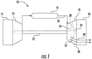
- FIG. 1 schematically illustrates a gas turbine engine 10.
- the gas turbine engine 10 may include an inlet section 12, a compressor section 14, a combustion section 16, a turbine section 18, and an exhaust section 20.
- the compressor section 14 and turbine section 18 may be coupled by a shaft 22.
- the shaft 22 may be a single shaft or a plurality of shaft segments coupled together to form the shaft 22.
- the turbine section 18 may include a rotor shaft 24 having a plurality of rotor disks 26 (one of which is shown) and a plurality of rotor blades 28. Each rotor blade 28 extends radially outward from and interconnects to one of the rotor disks 26. Each rotor disk 26, in turn, may be coupled to a portion of the rotor shaft 24 that extends through the turbine section 18.
- the turbine section 18 further includes an outer casing 30 that circumferentially surrounds the rotor shaft 24 and the rotor blades 28, thereby at least partially defining a hot gas path 32 through the turbine section 18.
- the gas turbine engine 10 produces mechanical rotational energy, which may, e.g., be used to generate electricity. More specifically, air enters the inlet section 12 of the gas turbine engine 10. From the inlet section 12, the air flows into the compressor 14, where it is progressively compressed to provide compressed air to the combustion section 16. The compressed air in the combustion section 16 mixes with a fuel to form an air-fuel mixture, which combusts to produce high temperature and high pressure combustion gases 34. The combustion gases 34 then flow through the turbine 18, which extracts kinetic and/or thermal energy from the combustion gases 34. This energy extraction rotates the rotor shaft 24, thereby creating mechanical rotational energy for powering the compressor section 14 and/or generating electricity. The combustion gases 34 exit the gas turbine engine 10 through the exhaust section 20.
- FIG. 2 is a side view of an exemplary rotor blade 100, which may be incorporated into the turbine section 18 of the gas turbine engine 10 in place of the rotor blade 28.
- the rotor blade 100 defines an axial direction A, a radial direction R, and a circumferential direction C.
- the axial direction A extends parallel to an axial centerline 102 of the shaft 24 ( FIG. 1 )
- the radial direction R extends generally orthogonal to the axial centerline 102
- the circumferential direction C extends generally concentrically around the axial centerline 102.
- the rotor blade 100 may also be incorporated into the compressor section 14 of the gas turbine engine 10 ( FIG. 1 ).
- the rotor blade 100 may include a dovetail 104, a shank portion 106, and a platform 108. More specifically, the dovetail 104 secures the rotor blade 100 to the rotor disk 26 ( FIG. 1 ).
- the shank portion 106 couples to and extends radially outward from the dovetail 104.
- the platform 108 couples to and extends radially outward from the shank portion 106.
- the platform 108 includes a radially outer surface 110, which generally serves as a radially inward flow boundary for the combustion gases 34 flowing through the hot gas path 32 of the turbine section 18 ( FIG. 1 ).
- the dovetail 104, the shank portion 106, and the platform 108 may define an intake port 112, which permits a coolant (e.g., bleed air from the compressor section 14) to enter the rotor blade 100.
- a coolant e.g., bleed air from the compressor section 14
- the dovetail 104 is an axial entry fir tree-type dovetail.
- the dovetail 104 may be any suitable type of dovetail.
- the dovetail 104, shank portion 106, and/or platform 108 may have any suitable configurations.
- the rotor blade 100 further includes an airfoil 114.
- the airfoil 114 extends radially outward from the radially outer surface 110 of the platform 108 to a tip shroud 116.
- the airfoil 114 couples to the platform 108 at a root 118 (i.e., the intersection between the airfoil 114 and the platform 116).
- the airfoil 118 defines an airfoil span 120 extending between the root 118 and the tip shroud 116.
- the airfoil 114 also includes a pressure side surface 122 and an opposing suction side surface 124 ( FIG. 3 ).
- the pressure side surface 122 and the suction side surface 124 are joined together or interconnected at a leading edge 126 of the airfoil 114 and a trailing edge 128 of the airfoil 114. As shown, the leading edge 126 is oriented into the flow of combustion gases 34 ( FIG. 1 ), while the trailing edge 128 is spaced apart from and positioned downstream of the leading edge 126.
- the pressure side surface 122 and the suction side surface 124 are continuous about the leading edge 126 and the trailing edge 128. Furthermore, the pressure side surface 122 is generally concave, and the suction side surface 124 is generally convex.
- the rotor blade 100 may define one or more radially-extending cooling passages 130 extending therethrough. More specifically, the radially-extending cooling passages 130 may extend from the intake port 112 through the airfoil 114 to the tip shroud 116. In this respect, coolant may flow through the radially-extending cooling passages 130 from the intake port 112 to the tip shroud 116.
- the airfoil 114 defines seven radially-extending cooling passages 130. In alternate embodiments, however, the airfoil 114 may define more or fewer radially-extending cooling passages 130.
- the rotor blade 100 includes the tip shroud 116.
- the tip shroud 116 couples to the radially outer end of the airfoil 114 and generally defines the radially outermost portion of the rotor blade 100.
- the tip shroud 116 reduces the amount of the combustion gases 34 ( FIG. 1 ) that escape past the rotor blade 100.
- the tip shroud 116 may include a seal rail 132. Alternate embodiments, however, may include more seal rails 132 (e.g., two seal rails 132, three seal rails 132, etc.) or no seal rails 132.
- the tip shroud 116 includes various surfaces.
- the tip shroud 116 may include a forward side surface 134 positioned at a forward end 136 of the tip shroud 116 and an aft side surface 138 positioned at an aft end 140 of the tip shroud 116.
- the tip shroud 116 may also include a first pressure side surface 142, a second pressure side surface 144, and a third pressure side surface 146 positioned on a pressure side 148 of the tip shroud 116.
- the tip shroud 116 may also include a first suction side surface 150, a second suction side surface 152, and a third suction side surface 154 positioned on a suction side 156 of the tip shroud 116.
- the surfaces 134, 138, 142, 144, 146, 150, 152, 154 maybe collectively referred to as a side surface 158.
- the tip shroud 114 also includes a radially outer surface 160 from which the seal rail 132 may extend outward. As shown, in some embodiments, the seal rail 152 may extend between the second pressure side surface 144 and the second suction side surface 152. In alternate embodiments, however, the tip shroud 116 may have any suitable combination and/or configuration of surfaces.
- the tip shroud 116 has a Z-notch configuration. More specifically, the first, second, and third pressure side walls 142, 144, 146 define a Z-shape. In this respect, a pressure side convex fillet 162 transitions between the first and second pressure side walls 142, 144, while a pressure side concave fillet 164 transitions between the second and third pressure side walls 144, 146.
- the first, second, and third suction side walls 150, 152, 154 define a Z-shape that is complementary to the Z-shape of the pressure side walls 142, 144, 146.
- a suction side concave fillet 166 transitions between the first and second suction side walls 150, 152, while a suction side convex fillet 168 transitions between the second and third suction side walls 152, 154.
- the tip shroud 116 may have any suitable shape and/or configuration.
- the tip shroud 116 may define pressure side and suction side cooling passages 170, 172. As shown, the cooling passages 170, 172 respectively extend from different radially-extending cooling passages 130 to pressure side and suction side outlets 174, 176 defined by the side surface 158.
- the pressure side cooling passage 170 is fluidly coupled to one of the radially-extending cooling passages 130, such as one of the cooling passages 130 positioned forward of the seal rail 132. As such, the pressure side cooling passage 170 extends through the tip shroud 116 to the pressure side outlet 174. As shown, the cooling passage 170 may be positioned forward of the seal rail 132 in some embodiments.
- the suction side cooling passage 172 is fluidly coupled to another of the radially-extending cooling passages 130, such as one of the cooling passages 130 positioned aft of the seal rail 132.
- the suction side cooling passage 172 extends through the tip shroud 116 to the suction side outlet 176.
- the cooling passage 170 maybe positioned aft of the seal rail 132 in some embodiments.
- the pressure side cooling passage 170 and outlet 174 may positioned aft of the seal rail 132 and the suction side cooling passage 172 and outlet 176 may be positioned forward of the seal rail 132.
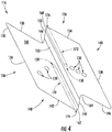
- the pressure side and suction side cooling passages 170, 172 extend toward the side surface 158 in opposite directions and may generally be parallel or substantially parallel to each other as shown in FIG. 4 .
- the cooling passages 170, 172 may extend along the seal rail 132, such as parallel or substantially parallel to the seal rail 132.
- the positioning of the cooling passage 170, 172 may be independent of the seal rail 132.
- the tip shroud 116 may entirely define the cooling passages 170, 172.
- the cooling passages 170, 172 may extend through the tip shroud 116 in any suitable manner.
- the tip shroud 116 may define only one of the pressure side or suction side cooling passages 170, 172.
- the pressure side and suction side cooling passages 170, 172 respectively have pressure side and suction side outlets 174, 176 defined by the side surface 158.
- the pressure side convex fillet 162 defines the pressure side outlet 174
- the suction side convex fillet 168 defines the suction side outlet 176.
- the outlets 174, 176 are configured to direct a flow of coolant onto the concave fillets 164, 166 of the adjacent rotor blades.
- the outlets 174, 176 may be configured to expel the coolant at a sufficient velocity to traverse a gap 182 ( FIG.
- outlets 174, 176 may have the same diameter as the corresponding cooling passage 170, 172 in some embodiments. In alternate embodiments, however, any suitable portion of the side surface 158 may define the outlets 174, 176 so long as the outlets 174, 176 may be configured to direct the flow of coolant onto suitable tip shroud fillets of the adjacent rotor blades.
- the tip shroud 116 may include a plug 178 positioned within a radially outer portion of the radially-extending cooling passages 130 to which the pressure side and/or suction side cooling passages 170, 172 fluidly couple.
- the plug 178 may direct coolant 180 flowing through the cooling passage 130 into the corresponding cooling passage 170, 172.
- the plug 178 may direct all of the coolant 180 flowing through the cooling passage 130 into the corresponding cooling passage 170, 172.
- the plug 178 may be a weld or other suitable structure that occludes the radially outer portion of the corresponding cooling passages 130.
- FIG. 6 illustrates a plurality of adjacent rotor blades 100.
- first, second, and third rotor blades 100A, 100B, 100C are axially aligned and circumferentially spaced apart.
- the pressure side outlet 174 of the first rotor blade 100A is axially aligned with the suction side concave fillet 166 of the second rotor blade 100B.
- the pressure side outlet 174 of the second rotor blade 100B is axially aligned with the suction side concave fillet 166 of the third rotor blade 100C.
- the suction side outlet 176 of the second rotor blade 100B is axially aligned with the pressure side concave fillet 164 of the first rotor blade 100A.
- the suction side outlet 176 of the third rotor blade 100A is axially aligned with the pressure side concave fillet 164 of the second rotor blade 100B.
- the outlets 174, 176 of the rotor blades 100A-C may be aligned with any suitable tip shroud fillets of the corresponding adjacent rotor blades.
- the coolant 180 flows through the pressure side and suction side cooling passages 170, 172 to respectively cool the pressure side concave fillet 166 and the suction side concave fillet 164 of the corresponding adjacent rotor blades 100A-C. More specifically, the coolant 180 (e.g., bleed air from the compressor section 14) enters the rotor blade 100 through the intake port 112 ( FIG. 2 ). At least a portion of the coolant 180 flows through the cooling passages 130 in the airfoil 114 and into the pressure side and/or suction side cooling passages 170, 172.
- the coolant 180 e.g., bleed air from the compressor section 14
- the coolant 180 exits the cooling passages 170, 172 respectively through the outlets 174, 176 and impinges on the adjacent concave fillets 164, 166, thereby cooling the concave fillets 164, 166.
- the coolant 180 exiting the outlet 174 of the first rotor blade 100A impinges on the concave fillet 166 of the second rotor blade 100B.
- the coolant 180 exiting the outlet 174 of the second rotor blade 100B impinges on the concave fillet 166 of the third rotor blade 100C.
- the coolant 180 exiting the outlet 176 of the second rotor blade impinges on the concave fillet 164 of the first rotor blade 100A.
- the coolant 180 exiting the outlet 176 of the third rotor blade 100A impinges on the concave fillet 164 of the second rotor blade 100B.
- the outlets 174, 176 expel the coolant at a sufficient velocity to traverse the gaps 182 between the outlets 174, 176 and the corresponding concave fillets 164, 166 to facilitate such impingement cooling.
- the rotor blade 100 includes a tip shroud 116 that defines a pressure side and/or suction side cooling passage 170, 172, which direct the coolant 180 onto the fillets 164, 166 of adjacent rotor blades.
- the rotor blade 100 provides greater cooling to the fillets 164, 166 of the tip shroud 116 than conventional rotor blades.
- the rotor blade 100 may be able to withstand higher operating temperatures and/or have a longer service life than conventional rotor blades.
Landscapes
- Engineering & Computer Science (AREA)
- Mechanical Engineering (AREA)
- General Engineering & Computer Science (AREA)
- Architecture (AREA)
- Turbine Rotor Nozzle Sealing (AREA)
Abstract
Description
- The present disclosure generally relates to turbomachines. More particularly, the present disclosure relates rotor blades for turbomachines.
- A gas turbine engine generally includes a compressor section, a combustion section, and a turbine section. The compressor section progressively increases the pressure of air entering the gas turbine engine and supplies this compressed air to the combustion section. The compressed air and a fuel (e.g., natural gas) mix within the combustion section and burn within one or more combustion chambers to generate high pressure and high temperature combustion gases. The combustion gases flow from the combustion section into the turbine section where they expand to produce work. For example, expansion of the combustion gases in the turbine section may rotate a rotor shaft connected to a generator to produce electricity.
- The turbine section generally includes a plurality of rotor blades. Each rotor blade includes an airfoil positioned within the flow of the combustion gases. In this respect, the rotor blades extract kinetic energy and/or thermal energy from the combustion gases flowing through the turbine section. Some rotor blades may include a tip shroud coupled to the radially outer end of the airfoil. The tip shroud reduces the amount of combustion gases leaking past the rotor blade.
- The rotor blades generally operate in extremely high temperature environments. As such, the tip shroud of each rotor blade may define various cooling passages through which a coolant may flow. Nevertheless, the cooling passages may only provide limited cooling to certain portions of the tip shroud, such as various fillets. This may limit the operating temperature of the rotor blade and/or the service life of the rotor blade.
- Aspects and advantages of the technology will be set forth in part in the following description, or may be obvious from the description, or may be learned through practice of the technology.
- In one aspect, the present disclosure is directed to a rotor blade for a turbomachine. The rotor blade includes an airfoil and a tip shroud coupled to the airfoil. The tip shroud includes a side surface. The airfoil and the tip shroud define a first cooling passage. The tip shroud further defines a second passage in fluid communication with the first cooling passage. The second cooling passage extends from the first cooling passage to a first outlet defined by the side surface. The first outlet is configured to direct a flow of coolant onto a tip shroud fillet of a first adjacent rotor blade.
- In another aspect, the present disclosure is directed to a turbomachine including a turbine section having a plurality of rotor blades. A first rotor blade of the plurality of rotor blades includes an airfoil and a tip shroud coupled to the airfoil. The tip shroud includes a side surface. The airfoil and the tip shroud define a first cooling passage. The tip shroud further defines a second passage in fluid communication with the first cooling passage. The second cooling passage extends from the first cooling passage to a first outlet defined by the side surface. The first outlet is configured to direct a flow of coolant onto a tip shroud fillet of a second rotor blade of the plurality of rotor blades.
- These and other features, aspects and advantages of the present technology will become better understood with reference to the following description and appended claims. The accompanying drawings, which are incorporated in and constitute a part of this specification, illustrate embodiments of the technology and, together with the description, serve to explain the principles of the technology.
- A full and enabling disclosure of the present technology, including the best mode thereof, directed to one of ordinary skill in the art, is set forth in the specification, which makes reference to the appended figures, in which:
-
FIG. 1 is a schematic view of an exemplary gas turbine engine in accordance with the embodiments disclosed herein; -
FIG. 2 is a side view of an exemplary rotor blade in accordance with the embodiments disclosed herein; -
FIG. 3 is cross-sectional view of an exemplary airfoil in accordance with the embodiments disclosed herein; -
FIG. 4 is a top view of a tip shroud in accordance with the embodiments disclosed herein; -
FIG. 5 is a cross-sectional view of a portion of the tip shroud shown inFIG. 4 , illustrating a plug in accordance with the embodiments disclosed herein; and -
FIG. 6 is a top view of a plurality of adjacent rotor blades in accordance with the embodiments disclosed herein. - Repeat use of reference characters in the present specification and drawings is intended to represent the same or analogous features or elements of the present technology.
- Reference will now be made in detail to present embodiments of the technology, one or more examples of which are illustrated in the accompanying drawings. The detailed description uses numerical and letter designations to refer to features in the drawings. Like or similar designations in the drawings and description have been used to refer to like or similar parts of the technology. As used herein, the terms "first", "second", and "third" may be used interchangeably to distinguish one component from another and are not intended to signify location or importance of the individual components. The terms "upstream" and "downstream" refer to the relative direction with respect to fluid flow in a fluid pathway. For example, "upstream" refers to the direction from which the fluid flows, and "downstream" refers to the direction to which the fluid flows.
- Each example is provided by way of explanation of the technology, not limitation of the technology. In fact, it will be apparent to those skilled in the art that modifications and variations can be made in the present technology without departing from the scope or spirit thereof. For instance, features illustrated or described as part of one embodiment may be used on another embodiment to yield a still further embodiment. Thus, it is intended that the present technology covers such modifications and variations as come within the scope of the appended claims and their equivalents.
- Although an industrial or land-based gas turbine is shown and described herein, the present technology as shown and described herein is not limited to a land-based and/or industrial gas turbine unless otherwise specified in the claims. For example, the technology as described herein may be used in any type of turbomachine including, but not limited to, aviation gas turbines (e.g., turbofans, etc.), steam turbines, and marine gas turbines.
- Referring now to the drawings, wherein identical numerals indicate the same elements throughout the figures,
FIG. 1 schematically illustrates agas turbine engine 10. As shown, thegas turbine engine 10 may include aninlet section 12, acompressor section 14, acombustion section 16, aturbine section 18, and anexhaust section 20. Thecompressor section 14 andturbine section 18 may be coupled by ashaft 22. Theshaft 22 may be a single shaft or a plurality of shaft segments coupled together to form theshaft 22. - The
turbine section 18 may include arotor shaft 24 having a plurality of rotor disks 26 (one of which is shown) and a plurality ofrotor blades 28. Eachrotor blade 28 extends radially outward from and interconnects to one of therotor disks 26. Eachrotor disk 26, in turn, may be coupled to a portion of therotor shaft 24 that extends through theturbine section 18. Theturbine section 18 further includes anouter casing 30 that circumferentially surrounds therotor shaft 24 and therotor blades 28, thereby at least partially defining ahot gas path 32 through theturbine section 18. - During operation, the
gas turbine engine 10 produces mechanical rotational energy, which may, e.g., be used to generate electricity. More specifically, air enters theinlet section 12 of thegas turbine engine 10. From theinlet section 12, the air flows into thecompressor 14, where it is progressively compressed to provide compressed air to thecombustion section 16. The compressed air in thecombustion section 16 mixes with a fuel to form an air-fuel mixture, which combusts to produce high temperature and highpressure combustion gases 34. Thecombustion gases 34 then flow through theturbine 18, which extracts kinetic and/or thermal energy from thecombustion gases 34. This energy extraction rotates therotor shaft 24, thereby creating mechanical rotational energy for powering thecompressor section 14 and/or generating electricity. Thecombustion gases 34 exit thegas turbine engine 10 through theexhaust section 20. -
FIG. 2 is a side view of anexemplary rotor blade 100, which may be incorporated into theturbine section 18 of thegas turbine engine 10 in place of therotor blade 28. As shown, therotor blade 100 defines an axial direction A, a radial direction R, and a circumferential direction C. In general, the axial direction A extends parallel to anaxial centerline 102 of the shaft 24 (FIG. 1 ), the radial direction R extends generally orthogonal to theaxial centerline 102, and the circumferential direction C extends generally concentrically around theaxial centerline 102. Therotor blade 100 may also be incorporated into thecompressor section 14 of the gas turbine engine 10 (FIG. 1 ). - As illustrated in
FIG. 2 , therotor blade 100 may include adovetail 104, ashank portion 106, and aplatform 108. More specifically, thedovetail 104 secures therotor blade 100 to the rotor disk 26 (FIG. 1 ). Theshank portion 106 couples to and extends radially outward from thedovetail 104. Theplatform 108 couples to and extends radially outward from theshank portion 106. Theplatform 108 includes a radiallyouter surface 110, which generally serves as a radially inward flow boundary for thecombustion gases 34 flowing through thehot gas path 32 of the turbine section 18 (FIG. 1 ). Thedovetail 104, theshank portion 106, and theplatform 108 may define anintake port 112, which permits a coolant (e.g., bleed air from the compressor section 14) to enter therotor blade 100. In the embodiment shown inFIG. 2 , thedovetail 104 is an axial entry fir tree-type dovetail. Alternately, thedovetail 104 may be any suitable type of dovetail. In fact, thedovetail 104,shank portion 106, and/orplatform 108 may have any suitable configurations. - Referring now to
FIGS. 2 and3 , therotor blade 100 further includes anairfoil 114. In particular, theairfoil 114 extends radially outward from the radiallyouter surface 110 of theplatform 108 to atip shroud 116. Theairfoil 114 couples to theplatform 108 at a root 118 (i.e., the intersection between theairfoil 114 and the platform 116). In this respect, theairfoil 118 defines anairfoil span 120 extending between theroot 118 and thetip shroud 116. Theairfoil 114 also includes apressure side surface 122 and an opposing suction side surface 124 (FIG. 3 ). Thepressure side surface 122 and thesuction side surface 124 are joined together or interconnected at aleading edge 126 of theairfoil 114 and a trailingedge 128 of theairfoil 114. As shown, theleading edge 126 is oriented into the flow of combustion gases 34 (FIG. 1 ), while the trailingedge 128 is spaced apart from and positioned downstream of theleading edge 126. Thepressure side surface 122 and thesuction side surface 124 are continuous about theleading edge 126 and the trailingedge 128. Furthermore, thepressure side surface 122 is generally concave, and thesuction side surface 124 is generally convex. - As shown in
FIG. 3 , therotor blade 100, and, more particularly, theairfoil 114 and thetip shroud 116, may define one or more radially-extendingcooling passages 130 extending therethrough. More specifically, the radially-extendingcooling passages 130 may extend from theintake port 112 through theairfoil 114 to thetip shroud 116. In this respect, coolant may flow through the radially-extendingcooling passages 130 from theintake port 112 to thetip shroud 116. In the embodiment shown inFIG. 3 , for example, theairfoil 114 defines seven radially-extendingcooling passages 130. In alternate embodiments, however, theairfoil 114 may define more or fewer radially-extendingcooling passages 130. - As mentioned above, the
rotor blade 100 includes thetip shroud 116. As illustrated inFIGS. 2 and4 , thetip shroud 116 couples to the radially outer end of theairfoil 114 and generally defines the radially outermost portion of therotor blade 100. In this respect, thetip shroud 116 reduces the amount of the combustion gases 34 (FIG. 1 ) that escape past therotor blade 100. As shown, thetip shroud 116 may include aseal rail 132. Alternate embodiments, however, may include more seal rails 132 (e.g., twoseal rails 132, threeseal rails 132, etc.) or no seal rails 132. - Referring now to
FIG. 4 , thetip shroud 116 includes various surfaces. For example, thetip shroud 116 may include aforward side surface 134 positioned at aforward end 136 of thetip shroud 116 and anaft side surface 138 positioned at anaft end 140 of thetip shroud 116. Thetip shroud 116 may also include a firstpressure side surface 142, a secondpressure side surface 144, and a thirdpressure side surface 146 positioned on apressure side 148 of thetip shroud 116. Similarly, thetip shroud 116 may also include a firstsuction side surface 150, a secondsuction side surface 152, and a thirdsuction side surface 154 positioned on asuction side 156 of thetip shroud 116. Thesurfaces side surface 158. Furthermore, thetip shroud 114 also includes a radiallyouter surface 160 from which theseal rail 132 may extend outward. As shown, in some embodiments, theseal rail 152 may extend between the secondpressure side surface 144 and the secondsuction side surface 152. In alternate embodiments, however, thetip shroud 116 may have any suitable combination and/or configuration of surfaces. - In the embodiment shown in
FIG. 4 , thetip shroud 116 has a Z-notch configuration. More specifically, the first, second, and thirdpressure side walls convex fillet 162 transitions between the first and secondpressure side walls concave fillet 164 transitions between the second and thirdpressure side walls suction side walls pressure side walls concave fillet 166 transitions between the first and secondsuction side walls convex fillet 168 transitions between the second and thirdsuction side walls tip shroud 116 may have any suitable shape and/or configuration. - The
tip shroud 116 may define pressure side and suctionside cooling passages cooling passages cooling passages 130 to pressure side andsuction side outlets side surface 158. For example, the pressureside cooling passage 170 is fluidly coupled to one of the radially-extendingcooling passages 130, such as one of thecooling passages 130 positioned forward of theseal rail 132. As such, the pressureside cooling passage 170 extends through thetip shroud 116 to thepressure side outlet 174. As shown, thecooling passage 170 may be positioned forward of theseal rail 132 in some embodiments. Similarly, the suctionside cooling passage 172 is fluidly coupled to another of the radially-extendingcooling passages 130, such as one of thecooling passages 130 positioned aft of theseal rail 132. In this respect, the suctionside cooling passage 172 extends through thetip shroud 116 to thesuction side outlet 176. As shown, thecooling passage 170 maybe positioned aft of theseal rail 132 in some embodiments. In alternate embodiments, the pressureside cooling passage 170 andoutlet 174 may positioned aft of theseal rail 132 and the suctionside cooling passage 172 andoutlet 176 may be positioned forward of theseal rail 132. The pressure side and suctionside cooling passages side surface 158 in opposite directions and may generally be parallel or substantially parallel to each other as shown inFIG. 4 . In certain embodiments, thecooling passages seal rail 132, such as parallel or substantially parallel to theseal rail 132. Although, in other embodiments, the positioning of thecooling passage seal rail 132. Thetip shroud 116 may entirely define thecooling passages cooling passages tip shroud 116 in any suitable manner. In further embodiments, thetip shroud 116 may define only one of the pressure side or suctionside cooling passages - As mentioned above, the pressure side and suction
side cooling passages suction side outlets side surface 158. In the embodiment shown inFIG. 4 , the pressure sideconvex fillet 162 defines thepressure side outlet 174 and the suction sideconvex fillet 168 defines thesuction side outlet 176. In this respect, and as will be described in greater detail below, theoutlets concave fillets outlets FIG. 6 ) between theoutlet concave fillet concave fillet outlets corresponding cooling passage side surface 158 may define theoutlets outlets - Referring now to
FIG. 5 , thetip shroud 116 may include aplug 178 positioned within a radially outer portion of the radially-extendingcooling passages 130 to which the pressure side and/or suctionside cooling passages plug 178 may directcoolant 180 flowing through thecooling passage 130 into thecorresponding cooling passage plug 178 may direct all of thecoolant 180 flowing through thecooling passage 130 into thecorresponding cooling passage plug 178 may be a weld or other suitable structure that occludes the radially outer portion of thecorresponding cooling passages 130. -
FIG. 6 illustrates a plurality ofadjacent rotor blades 100. As shown, first, second, andthird rotor blades pressure side outlet 174 of thefirst rotor blade 100A is axially aligned with the suction sideconcave fillet 166 of thesecond rotor blade 100B. Similarly, thepressure side outlet 174 of thesecond rotor blade 100B is axially aligned with the suction sideconcave fillet 166 of the third rotor blade 100C. Furthermore, thesuction side outlet 176 of thesecond rotor blade 100B is axially aligned with the pressure sideconcave fillet 164 of thefirst rotor blade 100A. Similarly, thesuction side outlet 176 of thethird rotor blade 100A is axially aligned with the pressure sideconcave fillet 164 of thesecond rotor blade 100B. In alternate embodiments, theoutlets rotor blades 100A-C may be aligned with any suitable tip shroud fillets of the corresponding adjacent rotor blades. - During operation of the
gas turbine engine 10, thecoolant 180 flows through the pressure side and suctionside cooling passages concave fillet 166 and the suction sideconcave fillet 164 of the correspondingadjacent rotor blades 100A-C. More specifically, the coolant 180 (e.g., bleed air from the compressor section 14) enters therotor blade 100 through the intake port 112 (FIG. 2 ). At least a portion of thecoolant 180 flows through thecooling passages 130 in theairfoil 114 and into the pressure side and/or suctionside cooling passages coolant 180 exits thecooling passages outlets concave fillets concave fillets coolant 180 exiting theoutlet 174 of thefirst rotor blade 100A impinges on theconcave fillet 166 of thesecond rotor blade 100B. Similarly, thecoolant 180 exiting theoutlet 174 of thesecond rotor blade 100B impinges on theconcave fillet 166 of the third rotor blade 100C. Furthermore, thecoolant 180 exiting theoutlet 176 of the second rotor blade impinges on theconcave fillet 164 of thefirst rotor blade 100A. Similarly, thecoolant 180 exiting theoutlet 176 of thethird rotor blade 100A impinges on theconcave fillet 164 of thesecond rotor blade 100B. In this respect, theoutlets gaps 182 between theoutlets concave fillets - As described in greater detail, above the
rotor blade 100 includes atip shroud 116 that defines a pressure side and/or suctionside cooling passage coolant 180 onto thefillets rotor blade 100 provides greater cooling to thefillets tip shroud 116 than conventional rotor blades. As such, therotor blade 100 may be able to withstand higher operating temperatures and/or have a longer service life than conventional rotor blades. - This written description uses examples to disclose the technology and also to enable any person skilled in the art to practice the technology, including making and using any devices or systems and performing any incorporated methods. The patentable scope of the technology is defined by the claims, and may include other examples that occur to those skilled in the art. Such other examples are intended to be within the scope of the claims if they include structural elements that do not differ from the literal language of the claims, or if they include equivalent structural elements with insubstantial differences from the literal language of the claims.
- Various aspects and embodiments of the present invention are defined by the following numbered clauses:
- 1. A rotor blade for a turbomachine, the rotor blade comprising:
- an airfoil; and
- a tip shroud coupled to the airfoil, the tip shroud including a side surface, the airfoil and the tip shroud defining a first cooling passage, the tip shroud further defining a second cooling passage in fluid communication with the first cooling passage, the second cooling passage extending from the first cooling passage to a first outlet defined by the side surface, the first outlet being configured to direct a coolant onto a tip shroud fillet of a first adjacent rotor blade.
- 2. The rotor blade of clause 1, wherein the first outlet is configured to expel the coolant at a sufficient velocity to traverse a gap between the outlet and the tip shroud fillet such that the coolant impinges on the tip shroud fillet of the first adjacent rotor blade.
- 3. The rotor blade of any preceding clause, wherein the tip shroud entirely defines the second cooling passage.
- 4. The rotor blade of any preceding clause, wherein the tip shroud comprises a seal rail extending outward from a radially outer surface of the tip shroud, the second cooling passage extending along the seal rail.
- 5. The rotor blade of any preceding clause, wherein the tip shroud comprises a plug positioned in a radially outer end of the first cooling passage to direct the coolant flowing through the first cooling passage into the second cooling passage.
- 6. The rotor blade of any preceding clause, wherein the plug directs all of the coolant flowing through the first cooling passage into the second cooling passage.
- 7. The rotor blade of any preceding clause, wherein the airfoil and the tip shroud further define a third cooling passage, the tip shroud further defining a fourth cooling passage in fluid communication with the third cooling passage, the fourth cooling passage extending from the third cooling passage to a second outlet defined by the side surface, the second outlet being configured to direct the coolant onto a tip shroud fillet of a second adjacent rotor blade.
- 8. The rotor blade of any preceding clause, wherein the first outlet is positioned on a pressure side of the tip shroud and the second outlet is positioned on a suction side of the tip shroud.
- 9. The rotor blade of any preceding clause, wherein the tip shroud comprises a seal rail extending outward from a radially outer surface of the tip shroud, the second cooling passage being positioned forward of the seal rail and the fourth cooling passage being positioned aft of the seal rail.
- 10. The rotor blade of any preceding clause, wherein the second cooling passage and the fourth cooling passage are substantially parallel.
- 11. A turbomachine, comprising:
a turbine section including a plurality of rotor blades, a first rotor blade of the plurality of rotor blades comprising:
an airfoil; and a tip shroud coupled to the airfoil, the tip shroud including a side surface, the airfoil and the tip shroud defining a first cooling passage, the tip shroud further defining a second cooling passage in fluid communication with the first cooling passage, the second cooling passage extending from the first cooling passage to a first outlet defined by the side surface, the first outlet being configured to direct a coolant onto a tip shroud fillet of a second rotor blade of the plurality of rotor blades. - 12. The turbomachine of any preceding clause, wherein the first outlet is configured to expel the coolant at a sufficient velocity to traverse a gap between the outlet and the tip shroud fillet such that the coolant impinges on the tip shroud fillet of the first adjacent rotor blade.
- 13. The turbomachine of any preceding clause, wherein the tip shroud entirely defines the second cooling passage.
- 14. The turbomachine of any preceding clause, wherein the tip shroud comprises a seal rail extending outward from a radially outer surface of the tip shroud, the second cooling passage extending along the seal rail.
- 15. The turbomachine of any preceding clause, wherein the tip shroud comprises a plug positioned in a radially outer end of the first cooling passage to direct the coolant flowing through the first cooling passage into the second cooling passage.
- 16. The turbomachine of any preceding clause, wherein the plug directs all of the coolant flowing through the first cooling passage into the second cooling passage.
- 17. The turbomachine of any preceding clause, wherein the airfoil and the tip shroud further define a third cooling passage, the tip shroud further defining a fourth cooling passage in fluid communication with the third cooling passage, the fourth cooling passage extending from the third cooling passage to a second outlet defined by the side surface, the second outlet being configured to direct the coolant onto a tip shroud fillet of a third rotor blade of the plurality of rotor blades.
- 18. The turbomachine of any preceding clause, wherein the first outlet is positioned on a pressure-side of the tip shroud and the second outlet is positioned on a suction-side of the tip shroud.
- 19. The turbomachine of any preceding clause, wherein the tip shroud comprises a seal rail extending outward from a radially outer surface of the tip shroud, the second cooling passage being positioned forward of the seal rail and the fourth cooling passage being positioned aft of the seal rail.
- 20. The turbomachine of any preceding clause, wherein the second cooling passage and the fourth cooling passage are substantially parallel.
Claims (15)
- A rotor blade (100) for a turbomachine (10), the rotor blade (100) comprising:
an airfoil (114); and
a tip shroud (116) coupled to the airfoil (114), the tip shroud (116) including a side surface (158), the airfoil (114) and the tip shroud (116) defining a first cooling passage (130), the tip shroud (116) further defining a second cooling passage (170, 172) in fluid communication with the first cooling passage (130), the second cooling passage (170, 172) extending from the first cooling passage (130) to a first outlet (174, 176) defined by the side surface (158), the first outlet (174, 176) being configured to direct a coolant (180) onto a tip shroud fillet (162, 164, 166, 168) of a first adjacent rotor blade (100). - The rotor blade (100) of claim 1, wherein the first outlet (174, 176) is configured to expel the coolant (180) at a sufficient velocity to traverse a gap (182) between the first outlet (174, 176) and the tip shroud fillet (162, 164, 166, 168) such that the coolant (180) impinges on the tip shroud fillet (162, 164, 166, 168) of the first adjacent rotor blade (100).
- The rotor blade (100) of claim 1 or 2, wherein the tip shroud (116) entirely defines the second cooling passage (170, 172).
- The rotor blade (100) of claim 1, 2 or 3, wherein the tip shroud (116) comprises a seal rail (132) extending outward from a radially outer surface (160) of the tip shroud (116), the second cooling passage (170, 172) extending along the seal rail (132).
- The rotor blade (100) of claim 1, 2 or 3, wherein the tip shroud (116) comprises a plug (178) positioned in a radially outer end of the first cooling passage (130) to direct the coolant (180) flowing through the first cooling passage (130) into the second cooling passage (170, 172).
- The rotor blade (100) of claim 5, wherein the plug (178) directs all of the coolant (180) flowing through the first cooling passage (130) into the second cooling passage (170, 172).
- The rotor blade (100) of any preceding claim, wherein the airfoil (114) and the tip shroud (116) further define a third cooling passage (130), the tip shroud (116) further defining a fourth cooling passage (170, 172) in fluid communication with the third cooling passage (130), the fourth cooling passage (170, 172) extending from the third cooling passage (130) to a second outlet (174, 176) defined by the side surface (158), the second outlet (174, 176) being configured to direct the coolant (180) onto a tip shroud fillet (162, 164, 166, 168) of a second adjacent rotor blade (100).
- The rotor blade (100) of claim 7, wherein the first outlet (174, 176) is positioned on a pressure side (148) of the tip shroud (116) and the second outlet (174, 176) is positioned on a suction side (156) of the tip shroud (116).
- The rotor blade (100) of claim 7 or 8, wherein the tip shroud (116) comprises a seal rail (132) extending outward from a radially outer surface (160) of the tip shroud (116), the second cooling passage (170, 172) being positioned forward of the seal rail (132) and the fourth cooling passage (170, 172) being positioned aft of the seal rail (132).
- The rotor blade (100) of claim 7, 8 or 9, wherein the second cooling passage (170, 172) and the fourth cooling passage (170, 172) are substantially parallel.
- A turbomachine (10), comprising:
a turbine section (18) including a plurality of rotor blades (100), a first rotor blade (100) of the plurality of rotor blades (100) comprising:an airfoil (114); anda tip shroud (116) coupled to the airfoil (114), the tip shroud (116) including a side surface (158), the airfoil (114) and the tip shroud (116) defining a first cooling passage (130), the tip shroud (116) further defining a second cooling passage (170, 172) in fluid communication with the first cooling passage (130), the second cooling passage (170, 172) extending from the first cooling passage (130) to a first outlet (174, 176) defined by the side surface (158), the first outlet (174, 176) being configured to direct a coolant (180) onto a tip shroud fillet (162, 164, 166, 168) of a second rotor blade (100) of the plurality of rotor blades (100). - The turbomachine (10) of claim 11, wherein the first outlet (174, 176) is configured to expel the coolant (180) at a sufficient velocity to traverse a gap (182) between the outlet and the tip shroud fillet (162, 164, 166, 168) such that the coolant (180) impinges on the tip shroud fillet (162, 164, 166, 168) of the first adjacent rotor blade (100).
- The turbomachine (10) of claim 11 or 12, wherein the tip shroud (116) entirely defines the second cooling passage (170, 172).
- The turbomachine (10) of claim 11, 12 or 13, wherein the tip shroud (116) comprises a seal rail (132) extending outward from a radially outer surface (160) of the tip shroud (116), the second cooling passage (170, 172) extending along the seal rail (132).
- The turbomachine (10) of claim 11, 12 or 13, wherein the tip shroud (116) comprises a plug (178) positioned in a radially outer end of the first cooling passage (130) to direct the coolant (180) flowing through the first cooling passage (130) into the second cooling passage (170, 172).
Applications Claiming Priority (1)
| Application Number | Priority Date | Filing Date | Title |
|---|---|---|---|
| US15/630,067 US11060407B2 (en) | 2017-06-22 | 2017-06-22 | Turbomachine rotor blade |
Publications (3)
| Publication Number | Publication Date |
|---|---|
| EP3418496A2 true EP3418496A2 (en) | 2018-12-26 |
| EP3418496A3 EP3418496A3 (en) | 2019-01-02 |
| EP3418496B1 EP3418496B1 (en) | 2024-10-09 |
Family
ID=62712824
Family Applications (1)
| Application Number | Title | Priority Date | Filing Date |
|---|---|---|---|
| EP18178422.4A Active EP3418496B1 (en) | 2017-06-22 | 2018-06-19 | A rotor blade for a turbomachine |
Country Status (5)
| Country | Link |
|---|---|
| US (1) | US11060407B2 (en) |
| EP (1) | EP3418496B1 (en) |
| JP (1) | JP7297413B2 (en) |
| KR (2) | KR20190000306A (en) |
| CN (1) | CN109113796A (en) |
Families Citing this family (3)
| Publication number | Priority date | Publication date | Assignee | Title |
|---|---|---|---|---|
| US20220090504A1 (en) * | 2020-09-24 | 2022-03-24 | General Electric Company | Rotor blade for a gas turbine engine having a metallic structural member and a composite fairing |
| GB202213805D0 (en) | 2022-09-22 | 2022-11-09 | Rolls Royce Plc | Platform for stator vane |
| GB202213804D0 (en) * | 2022-09-22 | 2022-11-09 | Rolls Royce Plc | Platform for stator vane |
Family Cites Families (38)
| Publication number | Priority date | Publication date | Assignee | Title |
|---|---|---|---|---|
| GB1423833A (en) | 1972-04-20 | 1976-02-04 | Rolls Royce | Rotor blades for fluid flow machines |
| FR2275975A5 (en) | 1973-03-20 | 1976-01-16 | Snecma | Gas turbine blade with cooling passages - holes parallel to blade axis provide surface layer of cool air |
| GB1514613A (en) | 1976-04-08 | 1978-06-14 | Rolls Royce | Blade or vane for a gas turbine engine |
| GB2223276B (en) * | 1988-09-30 | 1992-09-02 | Rolls Royce Plc | Turbine aerofoil blade |
| US5482435A (en) * | 1994-10-26 | 1996-01-09 | Westinghouse Electric Corporation | Gas turbine blade having a cooled shroud |
| US5785496A (en) * | 1997-02-24 | 1998-07-28 | Mitsubishi Heavy Industries, Ltd. | Gas turbine rotor |
| JPH1113402A (en) * | 1997-06-23 | 1999-01-19 | Mitsubishi Heavy Ind Ltd | Tip shroud for gas turbine cooling blade |
| JP2955252B2 (en) * | 1997-06-26 | 1999-10-04 | 三菱重工業株式会社 | Gas turbine blade tip shroud |
| JP3510467B2 (en) * | 1998-01-13 | 2004-03-29 | 三菱重工業株式会社 | Gas turbine blades |
| EP1391581B1 (en) * | 1998-02-04 | 2013-04-17 | Mitsubishi Heavy Industries, Ltd. | Gas turbine moving blade |
| EP1041247B1 (en) | 1999-04-01 | 2012-08-01 | General Electric Company | Gas turbine airfoil comprising an open cooling circuit |
| US6254345B1 (en) | 1999-09-07 | 2001-07-03 | General Electric Company | Internally cooled blade tip shroud |
| US6811378B2 (en) * | 2002-07-31 | 2004-11-02 | Power Systems Mfg, Llc | Insulated cooling passageway for cooling a shroud of a turbine blade |
| EP1591626A1 (en) | 2004-04-30 | 2005-11-02 | Alstom Technology Ltd | Blade for gas turbine |
| US7837440B2 (en) * | 2005-06-16 | 2010-11-23 | General Electric Company | Turbine bucket tip cap |
| US7387488B2 (en) * | 2005-08-05 | 2008-06-17 | General Electric Company | Cooled turbine shroud |
| US7686581B2 (en) | 2006-06-07 | 2010-03-30 | General Electric Company | Serpentine cooling circuit and method for cooling tip shroud |
| US7568882B2 (en) * | 2007-01-12 | 2009-08-04 | General Electric Company | Impingement cooled bucket shroud, turbine rotor incorporating the same, and cooling method |
| US7887295B2 (en) * | 2007-11-08 | 2011-02-15 | General Electric Company | Z-Notch shape for a turbine blade |
| US7946816B2 (en) | 2008-01-10 | 2011-05-24 | General Electric Company | Turbine blade tip shroud |
| US8057177B2 (en) | 2008-01-10 | 2011-11-15 | General Electric Company | Turbine blade tip shroud |
| EP2180142B1 (en) * | 2008-10-23 | 2014-01-22 | Alstom Technology Ltd | Blade for a gas turbine |
| US8096767B1 (en) * | 2009-02-04 | 2012-01-17 | Florida Turbine Technologies, Inc. | Turbine blade with serpentine cooling circuit formed within the tip shroud |
| CH700686A1 (en) | 2009-03-30 | 2010-09-30 | Alstom Technology Ltd | Blade for a gas turbine. |
| US20120177479A1 (en) * | 2011-01-06 | 2012-07-12 | Gm Salam Azad | Inner shroud cooling arrangement in a gas turbine engine |
| JP5868609B2 (en) | 2011-04-18 | 2016-02-24 | 三菱重工業株式会社 | Gas turbine blade and method for manufacturing the same |
| US8956104B2 (en) * | 2011-10-12 | 2015-02-17 | General Electric Company | Bucket assembly for turbine system |
| JP5881369B2 (en) * | 2011-10-27 | 2016-03-09 | 三菱重工業株式会社 | Turbine blade and gas turbine provided with the same |
| US9127560B2 (en) | 2011-12-01 | 2015-09-08 | General Electric Company | Cooled turbine blade and method for cooling a turbine blade |
| EP2607629A1 (en) | 2011-12-22 | 2013-06-26 | Alstom Technology Ltd | Shrouded turbine blade with cooling air outlet port on the blade tip and corresponding manufacturing method |
| US9845696B2 (en) * | 2014-12-15 | 2017-12-19 | Pratt & Whitney Canada Corp. | Turbine shroud sealing architecture |
| JP6025940B1 (en) | 2015-08-25 | 2016-11-16 | 三菱日立パワーシステムズ株式会社 | Turbine blade and gas turbine |
| US9885243B2 (en) | 2015-10-27 | 2018-02-06 | General Electric Company | Turbine bucket having outlet path in shroud |
| US10156145B2 (en) | 2015-10-27 | 2018-12-18 | General Electric Company | Turbine bucket having cooling passageway |
| US10508554B2 (en) | 2015-10-27 | 2019-12-17 | General Electric Company | Turbine bucket having outlet path in shroud |
| US10202852B2 (en) | 2015-11-16 | 2019-02-12 | General Electric Company | Rotor blade with tip shroud cooling passages and method of making same |
| US10156142B2 (en) * | 2015-11-24 | 2018-12-18 | General Electric Company | Systems and methods for producing one or more cooling holes in an airfoil for a gas turbine engine |
| DE102016222720A1 (en) * | 2016-11-18 | 2018-05-24 | MTU Aero Engines AG | Sealing system for an axial flow machine and axial flow machine |
-
2017
- 2017-06-22 US US15/630,067 patent/US11060407B2/en active Active
-
2018
- 2018-06-15 JP JP2018114093A patent/JP7297413B2/en active Active
- 2018-06-19 KR KR1020180070260A patent/KR20190000306A/en not_active Ceased
- 2018-06-19 EP EP18178422.4A patent/EP3418496B1/en active Active
- 2018-06-22 CN CN201810650809.7A patent/CN109113796A/en active Pending
-
2024
- 2024-10-21 KR KR1020240144153A patent/KR102944040B1/en active Active
Non-Patent Citations (1)
| Title |
|---|
| None |
Also Published As
| Publication number | Publication date |
|---|---|
| JP7297413B2 (en) | 2023-06-26 |
| KR20240164477A (en) | 2024-11-19 |
| KR102944040B1 (en) | 2026-03-25 |
| EP3418496A3 (en) | 2019-01-02 |
| US20180371921A1 (en) | 2018-12-27 |
| US11060407B2 (en) | 2021-07-13 |
| EP3418496B1 (en) | 2024-10-09 |
| KR20190000306A (en) | 2019-01-02 |
| JP2019011756A (en) | 2019-01-24 |
| CN109113796A (en) | 2019-01-01 |
Similar Documents
| Publication | Publication Date | Title |
|---|---|---|
| CN107435561B (en) | System for cooling seal rails of tip shroud of turbine blade | |
| US10830082B2 (en) | Systems including rotor blade tips and circumferentially grooved shrouds | |
| EP3415719B1 (en) | Turbomachine blade cooling structure | |
| US20120003091A1 (en) | Rotor assembly for use in gas turbine engines and method for assembling the same | |
| EP3088674A1 (en) | Rotor blade and corresponding gas turbine | |
| EP3214271B1 (en) | Rotor blade trailing edge cooling | |
| KR102944040B1 (en) | Turbomachine rotor blade | |
| US10301943B2 (en) | Turbomachine rotor blade | |
| EP3203024A1 (en) | Rotor blade and corresponding gas turbine | |
| EP3249162B1 (en) | Rotor blade and corresponding gas turbine system | |
| US10590777B2 (en) | Turbomachine rotor blade | |
| EP3412869B1 (en) | Turbomachine rotor blade | |
| US10494932B2 (en) | Turbomachine rotor blade cooling passage | |
| US10472974B2 (en) | Turbomachine rotor blade | |
| US10577945B2 (en) | Turbomachine rotor blade | |
| US20190003320A1 (en) | Turbomachine rotor blade | |
| US10746029B2 (en) | Turbomachine rotor blade tip shroud cavity | |
| US10633979B2 (en) | Turbomachine rotor blade pocket |
Legal Events
| Date | Code | Title | Description |
|---|---|---|---|
| PUAI | Public reference made under article 153(3) epc to a published international application that has entered the european phase |
Free format text: ORIGINAL CODE: 0009012 |
|
| STAA | Information on the status of an ep patent application or granted ep patent |
Free format text: STATUS: THE APPLICATION HAS BEEN PUBLISHED |
|
| PUAL | Search report despatched |
Free format text: ORIGINAL CODE: 0009013 |
|
| AK | Designated contracting states |
Kind code of ref document: A2 Designated state(s): AL AT BE BG CH CY CZ DE DK EE ES FI FR GB GR HR HU IE IS IT LI LT LU LV MC MK MT NL NO PL PT RO RS SE SI SK SM TR |
|
| AX | Request for extension of the european patent |
Extension state: BA ME |
|
| AK | Designated contracting states |
Kind code of ref document: A3 Designated state(s): AL AT BE BG CH CY CZ DE DK EE ES FI FR GB GR HR HU IE IS IT LI LT LU LV MC MK MT NL NO PL PT RO RS SE SI SK SM TR |
|
| AX | Request for extension of the european patent |
Extension state: BA ME |
|
| RIC1 | Information provided on ipc code assigned before grant |
Ipc: F01D 5/22 20060101AFI20181123BHEP |
|
| STAA | Information on the status of an ep patent application or granted ep patent |
Free format text: STATUS: REQUEST FOR EXAMINATION WAS MADE |
|
| 17P | Request for examination filed |
Effective date: 20190625 |
|
| RBV | Designated contracting states (corrected) |
Designated state(s): AL AT BE BG CH CY CZ DE DK EE ES FI FR GB GR HR HU IE IS IT LI LT LU LV MC MK MT NL NO PL PT RO RS SE SI SK SM TR |
|
| STAA | Information on the status of an ep patent application or granted ep patent |
Free format text: STATUS: EXAMINATION IS IN PROGRESS |
|
| 17Q | First examination report despatched |
Effective date: 20210201 |
|
| RAP1 | Party data changed (applicant data changed or rights of an application transferred) |
Owner name: GENERAL ELECTRIC TECHNOLOGY GMBH |
|
| GRAP | Despatch of communication of intention to grant a patent |
Free format text: ORIGINAL CODE: EPIDOSNIGR1 |
|
| STAA | Information on the status of an ep patent application or granted ep patent |
Free format text: STATUS: GRANT OF PATENT IS INTENDED |
|
| INTG | Intention to grant announced |
Effective date: 20240402 |
|
| GRAS | Grant fee paid |
Free format text: ORIGINAL CODE: EPIDOSNIGR3 |
|
| GRAA | (expected) grant |
Free format text: ORIGINAL CODE: 0009210 |
|
| STAA | Information on the status of an ep patent application or granted ep patent |
Free format text: STATUS: THE PATENT HAS BEEN GRANTED |
|
| AK | Designated contracting states |
Kind code of ref document: B1 Designated state(s): AL AT BE BG CH CY CZ DE DK EE ES FI FR GB GR HR HU IE IS IT LI LT LU LV MC MK MT NL NO PL PT RO RS SE SI SK SM TR |
|
| REG | Reference to a national code |
Ref country code: CH Ref legal event code: EP |
|
| REG | Reference to a national code |
Ref country code: DE Ref legal event code: R096 Ref document number: 602018075121 Country of ref document: DE |
|
| REG | Reference to a national code |
Ref country code: IE Ref legal event code: FG4D |
|
| REG | Reference to a national code |
Ref country code: LT Ref legal event code: MG9D |
|
| REG | Reference to a national code |
Ref country code: NL Ref legal event code: MP Effective date: 20241009 |
|
| REG | Reference to a national code |
Ref country code: AT Ref legal event code: MK05 Ref document number: 1730794 Country of ref document: AT Kind code of ref document: T Effective date: 20241009 |
|
| PG25 | Lapsed in a contracting state [announced via postgrant information from national office to epo] |
Ref country code: NL Free format text: LAPSE BECAUSE OF FAILURE TO SUBMIT A TRANSLATION OF THE DESCRIPTION OR TO PAY THE FEE WITHIN THE PRESCRIBED TIME-LIMIT Effective date: 20241009 |
|
| PG25 | Lapsed in a contracting state [announced via postgrant information from national office to epo] |
Ref country code: NL Free format text: LAPSE BECAUSE OF FAILURE TO SUBMIT A TRANSLATION OF THE DESCRIPTION OR TO PAY THE FEE WITHIN THE PRESCRIBED TIME-LIMIT Effective date: 20241009 |
|
| PG25 | Lapsed in a contracting state [announced via postgrant information from national office to epo] |
Ref country code: HR Free format text: LAPSE BECAUSE OF FAILURE TO SUBMIT A TRANSLATION OF THE DESCRIPTION OR TO PAY THE FEE WITHIN THE PRESCRIBED TIME-LIMIT Effective date: 20241009 Ref country code: IS Free format text: LAPSE BECAUSE OF FAILURE TO SUBMIT A TRANSLATION OF THE DESCRIPTION OR TO PAY THE FEE WITHIN THE PRESCRIBED TIME-LIMIT Effective date: 20250209 Ref country code: PT Free format text: LAPSE BECAUSE OF FAILURE TO SUBMIT A TRANSLATION OF THE DESCRIPTION OR TO PAY THE FEE WITHIN THE PRESCRIBED TIME-LIMIT Effective date: 20250210 |
|
| PG25 | Lapsed in a contracting state [announced via postgrant information from national office to epo] |
Ref country code: FI Free format text: LAPSE BECAUSE OF FAILURE TO SUBMIT A TRANSLATION OF THE DESCRIPTION OR TO PAY THE FEE WITHIN THE PRESCRIBED TIME-LIMIT Effective date: 20241009 |
|
| PG25 | Lapsed in a contracting state [announced via postgrant information from national office to epo] |
Ref country code: BG Free format text: LAPSE BECAUSE OF FAILURE TO SUBMIT A TRANSLATION OF THE DESCRIPTION OR TO PAY THE FEE WITHIN THE PRESCRIBED TIME-LIMIT Effective date: 20241009 |
|
| PG25 | Lapsed in a contracting state [announced via postgrant information from national office to epo] |
Ref country code: ES Free format text: LAPSE BECAUSE OF FAILURE TO SUBMIT A TRANSLATION OF THE DESCRIPTION OR TO PAY THE FEE WITHIN THE PRESCRIBED TIME-LIMIT Effective date: 20241009 |
|
| PG25 | Lapsed in a contracting state [announced via postgrant information from national office to epo] |
Ref country code: NO Free format text: LAPSE BECAUSE OF FAILURE TO SUBMIT A TRANSLATION OF THE DESCRIPTION OR TO PAY THE FEE WITHIN THE PRESCRIBED TIME-LIMIT Effective date: 20250109 |
|
| PG25 | Lapsed in a contracting state [announced via postgrant information from national office to epo] |
Ref country code: LV Free format text: LAPSE BECAUSE OF FAILURE TO SUBMIT A TRANSLATION OF THE DESCRIPTION OR TO PAY THE FEE WITHIN THE PRESCRIBED TIME-LIMIT Effective date: 20241009 Ref country code: GR Free format text: LAPSE BECAUSE OF FAILURE TO SUBMIT A TRANSLATION OF THE DESCRIPTION OR TO PAY THE FEE WITHIN THE PRESCRIBED TIME-LIMIT Effective date: 20250110 Ref country code: AT Free format text: LAPSE BECAUSE OF FAILURE TO SUBMIT A TRANSLATION OF THE DESCRIPTION OR TO PAY THE FEE WITHIN THE PRESCRIBED TIME-LIMIT Effective date: 20241009 |
|
| PG25 | Lapsed in a contracting state [announced via postgrant information from national office to epo] |
Ref country code: PL Free format text: LAPSE BECAUSE OF FAILURE TO SUBMIT A TRANSLATION OF THE DESCRIPTION OR TO PAY THE FEE WITHIN THE PRESCRIBED TIME-LIMIT Effective date: 20241009 |
|
| PG25 | Lapsed in a contracting state [announced via postgrant information from national office to epo] |
Ref country code: RS Free format text: LAPSE BECAUSE OF FAILURE TO SUBMIT A TRANSLATION OF THE DESCRIPTION OR TO PAY THE FEE WITHIN THE PRESCRIBED TIME-LIMIT Effective date: 20250109 |
|
| PG25 | Lapsed in a contracting state [announced via postgrant information from national office to epo] |
Ref country code: SM Free format text: LAPSE BECAUSE OF FAILURE TO SUBMIT A TRANSLATION OF THE DESCRIPTION OR TO PAY THE FEE WITHIN THE PRESCRIBED TIME-LIMIT Effective date: 20241009 |
|
| PGFP | Annual fee paid to national office [announced via postgrant information from national office to epo] |
Ref country code: DE Payment date: 20250520 Year of fee payment: 8 |
|
| PG25 | Lapsed in a contracting state [announced via postgrant information from national office to epo] |
Ref country code: DK Free format text: LAPSE BECAUSE OF FAILURE TO SUBMIT A TRANSLATION OF THE DESCRIPTION OR TO PAY THE FEE WITHIN THE PRESCRIBED TIME-LIMIT Effective date: 20241009 |
|
| PGFP | Annual fee paid to national office [announced via postgrant information from national office to epo] |
Ref country code: GB Payment date: 20250520 Year of fee payment: 8 |
|
| REG | Reference to a national code |
Ref country code: DE Ref legal event code: R097 Ref document number: 602018075121 Country of ref document: DE |
|
| PG25 | Lapsed in a contracting state [announced via postgrant information from national office to epo] |
Ref country code: EE Free format text: LAPSE BECAUSE OF FAILURE TO SUBMIT A TRANSLATION OF THE DESCRIPTION OR TO PAY THE FEE WITHIN THE PRESCRIBED TIME-LIMIT Effective date: 20241009 |
|
| PG25 | Lapsed in a contracting state [announced via postgrant information from national office to epo] |
Ref country code: RO Free format text: LAPSE BECAUSE OF FAILURE TO SUBMIT A TRANSLATION OF THE DESCRIPTION OR TO PAY THE FEE WITHIN THE PRESCRIBED TIME-LIMIT Effective date: 20241009 |
|
| PG25 | Lapsed in a contracting state [announced via postgrant information from national office to epo] |
Ref country code: SK Free format text: LAPSE BECAUSE OF FAILURE TO SUBMIT A TRANSLATION OF THE DESCRIPTION OR TO PAY THE FEE WITHIN THE PRESCRIBED TIME-LIMIT Effective date: 20241009 |
|
| PG25 | Lapsed in a contracting state [announced via postgrant information from national office to epo] |
Ref country code: CZ Free format text: LAPSE BECAUSE OF FAILURE TO SUBMIT A TRANSLATION OF THE DESCRIPTION OR TO PAY THE FEE WITHIN THE PRESCRIBED TIME-LIMIT Effective date: 20241009 |
|
| PG25 | Lapsed in a contracting state [announced via postgrant information from national office to epo] |
Ref country code: IT Free format text: LAPSE BECAUSE OF FAILURE TO SUBMIT A TRANSLATION OF THE DESCRIPTION OR TO PAY THE FEE WITHIN THE PRESCRIBED TIME-LIMIT Effective date: 20241009 |
|
| PLBE | No opposition filed within time limit |
Free format text: ORIGINAL CODE: 0009261 |
|
| STAA | Information on the status of an ep patent application or granted ep patent |
Free format text: STATUS: NO OPPOSITION FILED WITHIN TIME LIMIT |
|
| PG25 | Lapsed in a contracting state [announced via postgrant information from national office to epo] |
Ref country code: SE Free format text: LAPSE BECAUSE OF FAILURE TO SUBMIT A TRANSLATION OF THE DESCRIPTION OR TO PAY THE FEE WITHIN THE PRESCRIBED TIME-LIMIT Effective date: 20241009 |
|
| 26N | No opposition filed |
Effective date: 20250710 |
|
| REG | Reference to a national code |
Ref country code: CH Ref legal event code: H13 Free format text: ST27 STATUS EVENT CODE: U-0-0-H10-H13 (AS PROVIDED BY THE NATIONAL OFFICE) Effective date: 20260127 |
|
| PG25 | Lapsed in a contracting state [announced via postgrant information from national office to epo] |
Ref country code: MC Free format text: LAPSE BECAUSE OF FAILURE TO SUBMIT A TRANSLATION OF THE DESCRIPTION OR TO PAY THE FEE WITHIN THE PRESCRIBED TIME-LIMIT Effective date: 20241009 |
|
| PG25 | Lapsed in a contracting state [announced via postgrant information from national office to epo] |
Ref country code: LU Free format text: LAPSE BECAUSE OF NON-PAYMENT OF DUE FEES Effective date: 20250619 |
|
| REG | Reference to a national code |
Ref country code: BE Ref legal event code: MM Effective date: 20250630 |
|
| PG25 | Lapsed in a contracting state [announced via postgrant information from national office to epo] |
Ref country code: IE Free format text: LAPSE BECAUSE OF NON-PAYMENT OF DUE FEES Effective date: 20250619 |
|
| PG25 | Lapsed in a contracting state [announced via postgrant information from national office to epo] |
Ref country code: BE Free format text: LAPSE BECAUSE OF NON-PAYMENT OF DUE FEES Effective date: 20250630 |
|
| PG25 | Lapsed in a contracting state [announced via postgrant information from national office to epo] |
Ref country code: FR Free format text: LAPSE BECAUSE OF NON-PAYMENT OF DUE FEES Effective date: 20250630 |
|
| PG25 | Lapsed in a contracting state [announced via postgrant information from national office to epo] |
Ref country code: CH Free format text: LAPSE BECAUSE OF NON-PAYMENT OF DUE FEES Effective date: 20250630 |