EP2180142B1 - Blade for a gas turbine - Google Patents
Blade for a gas turbine Download PDFInfo
- Publication number
- EP2180142B1 EP2180142B1 EP08167378.2A EP08167378A EP2180142B1 EP 2180142 B1 EP2180142 B1 EP 2180142B1 EP 08167378 A EP08167378 A EP 08167378A EP 2180142 B1 EP2180142 B1 EP 2180142B1
- Authority
- EP
- European Patent Office
- Prior art keywords
- blade
- fin
- shroud
- shroud segment
- fins
- Prior art date
- Legal status (The legal status is an assumption and is not a legal conclusion. Google has not performed a legal analysis and makes no representation as to the accuracy of the status listed.)
- Active
Links
Images


Classifications
-
- F—MECHANICAL ENGINEERING; LIGHTING; HEATING; WEAPONS; BLASTING
- F01—MACHINES OR ENGINES IN GENERAL; ENGINE PLANTS IN GENERAL; STEAM ENGINES
- F01D—NON-POSITIVE DISPLACEMENT MACHINES OR ENGINES, e.g. STEAM TURBINES
- F01D5/00—Blades; Blade-carrying members; Heating, heat-insulating, cooling or antivibration means on the blades or the members
- F01D5/12—Blades
- F01D5/22—Blade-to-blade connections, e.g. for damping vibrations
- F01D5/225—Blade-to-blade connections, e.g. for damping vibrations by shrouding
-
- F—MECHANICAL ENGINEERING; LIGHTING; HEATING; WEAPONS; BLASTING
- F05—INDEXING SCHEMES RELATING TO ENGINES OR PUMPS IN VARIOUS SUBCLASSES OF CLASSES F01-F04
- F05B—INDEXING SCHEME RELATING TO WIND, SPRING, WEIGHT, INERTIA OR LIKE MOTORS, TO MACHINES OR ENGINES FOR LIQUIDS COVERED BY SUBCLASSES F03B, F03D AND F03G
- F05B2240/00—Components
- F05B2240/20—Rotors
- F05B2240/33—Shrouds which are part of or which are rotating with the rotor
Definitions
- the present invention relates generally to the field of gas turbines. It is directed to a blade or a gas turbine according to the preamble of claim 1.
- Gas turbine rotor blades comprise blade shroud segments in order to control and minimise leakage flow between the blade tips and the surrounding stator as well as to limit vibration amplitudes.
- a blade shroud segment typically comprises a platform extending in a plane essentially parallel to the stator opposite to the blade tip and one or more fins, which extend circumferentially and radially outward toward the stator.
- the platform of a blade shroud segment is typically shaped such that its edges are parallel to those of an adjacent blade shroud platform.
- a cooling fluid e.g. cooling air
- a cooling system within the platform of the shroud that is fluidly connected to the hollow interior of the blade airfoil.
- the shroud lifetime is limited by the mechanical stresses caused by centrifugal forces. Such stresses are currently reduced by minimising the wall thickness of the platform, also known as shroud web.
- a blade shroud segment with a thin wall thickness may not line up with the blade shroud segment of the adjacent blade due to manufacturing and assembly tolerances, which occur even if the tolerances are kept at a minimum.
- a further mismatch results from deformations of the shroud platform during turbine operation due to thermal and mechanical loading.
- a mismatch between two adjacent blade shroud segments allows hot gas to enter the cavity between the stator and the blade shroud.
- the shroud is typically designed with materials having a creep resistance and oxidation resistance up to a temperature less than the temperature of the hot gas. Hot gas ingestion therefore causes premature failure of the shroud and the adjacent static and moving components.
- the EP-A1-1 591 625 discloses a gas turbine blade with a shroud segment, which comprises a platform extending for example in the plane essentially matching the contour of the stator opposite the blade tip, and side rails that extend radially and along one or both edges of the platform that face the platform of an adjacent gas turbine blade shroud segment.
- An increase of the wall thickness results in an increase of the stiffness of the component according to the third power of the wall thickness.
- the blade shroud segment of the EP-A1-1 591 625 has an increased wall thickness that is limited to the side regions of the platform.
- the increase in wall thickness is localised such that it causes no significant increase in the mass of the shroud segment and no significant increase of the mechanical loading.
- EP 1 890 008 A2 shows a rotor blade having two fins running parallel in a circumferential direction at its tip shroud and further first and second sections of increased and varying cross-sectional thickness arranged along the side edges of the tip shroud. The first and second sections are placed between two fins with a distance from each fin.
- each of said side rails is subdivided into sections by means of said plurality of fins such that between a first fin and a second fin there is a first side rail section with side rails of a first height and a first width extending from the first to the second fin, and between the second fin and a third fin there is a second side rail section with side rails of a second height different from the first height and a second width different from the first width extending from the second to the third fin.
- a second embodiment of the blade according to the invention is characterized in that, said fins are inclined with respect to said longitudinal axis of said blade.
- the ratio h/b of height to width of said side rails lies in the range 0.5 ⁇ h/b ⁇ 2, and preferably the ratio h/b of height to width of said side rails lies in the range 1.0 ⁇ h/b ⁇ 1.3.
- the shroud segment in order to avoid dead zones for the cooling air in the space between said side rails is provided with a fillet at the transition from each side rail to the upper side of the shroud segment, with a fillet radius in a range 0.5 mm ⁇ r1,r2 ⁇ 4.0 mm.
- openings are provided in said shroud segment between said fins for injecting cooling air from the inside of said airfoil into the space between said fins.
- said first and second edges are Z-shaped.
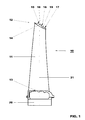
- Fig. 1 shows in a side view a blade 10 for a gas turbine according to a preferred embodiment of the invention.
- the blade 10 comprises an airfoil 11, which extends along a longitudinal axis 21 from a blade root 20 to a blade tip 12.
- the blade 10 has a platform-like shroud segment 14 at its blade tip 12.
- Mounted within the gas turbine the shroud segment 14 of the blade 10 abuts with first and second edges (22, 23 in Fig. 3 ) against similar shroud segments of adjacent blades to make up a ring-like shroud, which borders the hot gas channel of the turbine and defines a hollow space between the shroud ring and the surrounding stator, which is filled with cooling air.
- the first an second edges 22, 23 are each provided with a respective side rail 18 and 19 (18a,b and 19a,b in Fig. 5 and 6 ) on the upper side of said shroud segment 14.
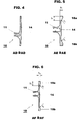
- the shroud segment 14 has on its upper side a plurality of fins 15, 16, 17, which are inclined with respect to the longitudinal axis 21 and run parallel to each other in a circumferential direction (Y in Fig. 3 ).
- the side rails are subdivided into sections 18, 19 of different height (h1, h2 in Fig. 5 und 6 ) and width (b1, b2 in Fig. 5 und 6 ) by means of said fins 15, 16, 17.
- first side rail section 18 cross-section AE-AE in Fig. 3 , 5
- first side rail section 19 cross-section AF-AF in Fig. 3 , 6
- second side rail section 19 cross-section AF-AF in Fig. 3 , 6
- Outside fin 15 there is no side rail at all (cross-section AD-AD in Fig. 3 , 4 ).
- the height h1 of the side rail section 18 in the central region of the shroud segment 14 between fin 15 and fin 16 is substantially larger than the height h2 of the side rail section 19 between fin 16 and fin 17.
- the ratio h/b of height h1, h2 to the respective width b1, b2 of said side rails 18, 19 lies in the range 0.5 ⁇ h/b ⁇ 2, and preferably in the range 1.0 ⁇ h/b ⁇ 1.3.
- the ratio h1/b1 amounts to 1.3, while the ratio h2/b2 is 1.0.
- the shroud segments 14 of the shroud ring with their fins 15, 16 and 17 establish, together with the surrounding stator, two ring-like hollow spaces, which are cooled by cooling air.
- openings 24, 25 are provided in each shroud segment 14 between said fins 15, 16 and 17, through which cooling air is injected into the space between said fins 15, 16 and 17.
- the shroud segment 14 is provided with a fillet at the transition from each side rail 18a,b and 19a,b to the upper side of the shroud segment 14, with the respective fillet radius r1, r2 lying in a range 0.5 mm ⁇ r1,r2 ⁇ 4.0 mm.
- the first and second edges 22, 23 of the shroud segment 14 are Z-shaped, whereby the edges 22, 23 run parallel between fins 16 and 17 and outside of fin 15, while they show a Z-like curvature between fins 15 and 16.
Description
- The present invention relates generally to the field of gas turbines. It is directed to a blade or a gas turbine according to the preamble of claim 1.
- Gas turbine rotor blades comprise blade shroud segments in order to control and minimise leakage flow between the blade tips and the surrounding stator as well as to limit vibration amplitudes. A blade shroud segment typically comprises a platform extending in a plane essentially parallel to the stator opposite to the blade tip and one or more fins, which extend circumferentially and radially outward toward the stator.
- The platform of a blade shroud segment is typically shaped such that its edges are parallel to those of an adjacent blade shroud platform. In order to withstand the high thermal load during gas turbine operation the blade shroud is cooled by means of a cooling fluid (e.g. cooling air) passing through a cooling system within the platform of the shroud that is fluidly connected to the hollow interior of the blade airfoil.
- The shroud lifetime is limited by the mechanical stresses caused by centrifugal forces. Such stresses are currently reduced by minimising the wall thickness of the platform, also known as shroud web. However, a blade shroud segment with a thin wall thickness may not line up with the blade shroud segment of the adjacent blade due to manufacturing and assembly tolerances, which occur even if the tolerances are kept at a minimum.
A further mismatch results from deformations of the shroud platform during turbine operation due to thermal and mechanical loading. A mismatch between two adjacent blade shroud segments allows hot gas to enter the cavity between the stator and the blade shroud. The shroud is typically designed with materials having a creep resistance and oxidation resistance up to a temperature less than the temperature of the hot gas. Hot gas ingestion therefore causes premature failure of the shroud and the adjacent static and moving components. - The
EP-A1-1 591 625 discloses a gas turbine blade with a shroud segment, which comprises a platform extending for example in the plane essentially matching the contour of the stator opposite the blade tip, and side rails that extend radially and along one or both edges of the platform that face the platform of an adjacent gas turbine blade shroud segment. - An increase of the wall thickness results in an increase of the stiffness of the component according to the third power of the wall thickness. The blade shroud segment of the
EP-A1-1 591 625 has an increased wall thickness that is limited to the side regions of the platform. Thus the benefits of increased stiffness are achieved and a resulting decreasing in deformation and bending in the radial outward direction with time of turbine operation. On the other hand, the increase in wall thickness is localised such that it causes no significant increase in the mass of the shroud segment and no significant increase of the mechanical loading. -
EP 1 890 008 A2 shows a rotor blade having two fins running parallel in a circumferential direction at its tip shroud and further first and second sections of increased and varying cross-sectional thickness arranged along the side edges of the tip shroud. The first and second sections are placed between two fins with a distance from each fin. - However, as there is either no side rail or a constant height side rail on the prior art shroud segments, there is still a lot of room for optimizing the geometry of the side rails for proper blade shroud segment coupling and simplified manufacturing, minimization of hot gas ingestion, improved stiffness and improved shroud cooling.
- It is therefore an objective of the invention, to provide a gas turbine blade with a shroud segment at the tip of the blade, which has and optimized geometry with respect to the side rails.
- This objective is achieved by a blade according to claim 1. A main feature of the blade according to the invention is that each of said side rails is subdivided into sections by means of said plurality of fins such that between a first fin and a second fin there is a first side rail section with side rails of a first height and a first width extending from the first to the second fin, and between the second fin and a third fin there is a second side rail section with side rails of a second height different from the first height and a second width different from the first width extending from the second to the third fin.
- A second embodiment of the blade according to the invention is characterized in that, said fins are inclined with respect to said longitudinal axis of said blade. Especially, the ratio h/b of height to width of said side rails lies in the range 0.5 ≤ h/b ≤ 2, and preferably the ratio h/b of height to width of said side rails lies in the range 1.0 ≤ h/b ≤ 1.3.
- According to another embodiment of the invention, in order to avoid dead zones for the cooling air in the space between said side rails the shroud segment is provided with a fillet at the transition from each side rail to the upper side of the shroud segment, with a fillet radius in a range 0.5 mm ≤ r1,r2 ≤ 4.0 mm.
- According to another embodiment of the invention openings are provided in said shroud segment between said fins for injecting cooling air from the inside of said airfoil into the space between said fins.
- According to still another embodiment of the invention said first and second edges are Z-shaped.
- The subject matter of the invention will be explained in more detail in the following text with reference to preferred exemplary embodiments which are illustrated in the attached drawings, in which:
- Fig. 1
- shows in a side view a blade for a gas turbine according to a preferred embodiment of the invention;
- Fig. 2
- the blade of
Fig. 1 in a perspective view; - Fig. 3
- a view from above on the blade according to
Fig. 1 ; - Fig. 4
- a cross-section of the shroud segment of
Fig. 3 along the plane AD-AD; - Fig. 5
- a cross-section of the shroud segment of
Fig. 3 along the plane AE-AE; and - Fig. 6
- a cross-section of the shroud segment of
Fig. 3 along the plane AF-AF. -
Fig. 1 shows in a side view ablade 10 for a gas turbine according to a preferred embodiment of the invention. Theblade 10 comprises anairfoil 11, which extends along alongitudinal axis 21 from ablade root 20 to ablade tip 12. Theblade 10 has a platform-like shroud segment 14 at itsblade tip 12. Mounted within the gas turbine theshroud segment 14 of theblade 10 abuts with first and second edges (22, 23 inFig. 3 ) against similar shroud segments of adjacent blades to make up a ring-like shroud, which borders the hot gas channel of the turbine and defines a hollow space between the shroud ring and the surrounding stator, which is filled with cooling air. The first ansecond edges respective side rail 18 and 19 (18a,b and 19a,b inFig. 5 and 6 ) on the upper side of saidshroud segment 14. - The
shroud segment 14 has on its upper side a plurality offins longitudinal axis 21 and run parallel to each other in a circumferential direction (Y inFig. 3 ). The side rails are subdivided intosections Fig. 5 und 6 ) and width (b1, b2 inFig. 5 und 6 ) by means of said fins 15, 16, 17. Betweenfin 15 andfin 16 there is a first side rail section 18 (cross-section AE-AE inFig. 3 ,5 ) with a first height h1 and a first width b1, and betweenfin 16 andfin 17 there is a second side rail section 19 (cross-section AF-AF inFig. 3 ,6 ) with a second height h2 and a second width b2. Outside fin 15, there is no side rail at all (cross-section AD-AD inFig. 3 ,4 ). - As can be seen form
Fig. 5 and 6 , the height h1 of theside rail section 18 in the central region of theshroud segment 14 betweenfin 15 andfin 16 is substantially larger than the height h2 of theside rail section 19 betweenfin 16 andfin 17. The ratio h/b of height h1, h2 to the respective width b1, b2 of saidside rails - The
shroud segments 14 of the shroud ring with theirfins Fig. 4-6 ),openings shroud segment 14 between said fins 15, 16 and 17, through which cooling air is injected into the space between said fins 15, 16 and 17. - In order to avoid dead zones for the cooling air in the space between said
side rails 18 19 theshroud segment 14 is provided with a fillet at the transition from eachside rail 18a,b and 19a,b to the upper side of theshroud segment 14, with the respective fillet radius r1, r2 lying in a range 0.5 mm ≤ r1,r2 ≤ 4.0 mm. - As can be seen in
Fig. 3 , the first andsecond edges shroud segment 14 are Z-shaped, whereby theedges fins fin 15, while they show a Z-like curvature betweenfins -
- 10
- Blade
- 11
- Airfoil
- 12
- Blade tip
- 13
- Platform
- 14
- Shroud segment
- 15,16,17
- Fin
- 18,19
- Side rail
- 18a,b
- Side rail
- 19a,b
- Side rail
- 20
- Blade root
- 21
- Longitudinal axis (blade)
- 22,23
- Edge
- 24,25
- Opening
- r1, r2
- Filet radius
- h1, h2
- Height
- b1, b2
- Width
- X
- Axial direction (machine axis)
- Y
- Circumferential direction (direction of rotation)
Claims (7)
- Blade (10) for a gas turbine, comprising an airfoil (11), which extends along a longitudinal axis (21) from a blade root (20) to a blade tip (12), and having a shroud segment (14) at said blade tip (12), which shroud segment (14) abuts with first and second edges (22, 23) against similar shroud segments of adjacent blades to make up a ring-like shroud, whereby said first and second edges (22, 23) are each provided with a respective side rail on the upper side of said shroud segment (14), and the shroud segment (14) comprises on its upper side a plurality of fins running parallel in a circumferential direction (Y), characterized in that said side rails (18a,18b;19a, 19b) are subdivided into sections by means of said plurality of fins (15, 16, 17) such that between a first fin (15) and a second fin (16) there is a first side rail section (18) with side rails (18a, 18b) of a first height (h1) and a first width (b1) extending from the first to the second fin, and between the second fin (16) and a third fin (17) there is a second side rail section (19) with side rails (19a, 19b) of a second height (h2) different from the first height (h1) and a second width (b2) different from the first width (b1) extending from the second to the third fin.
- Blade as claimed in claim 1, characterized in that said fins (15, 16, 17) are inclined with respect to said longitudinal axis (21) of said blade (10).
- Blade as claimed in claim 1 or 2, characterized in that the ratio h/b of height (h1, h2) to width (b1, b2) of said side rails (18a,b; 19a,b) lies in the range 0.5 ≤ h/b ≤ 2.
- Blade as claimed in claim 3, characterized in that the ratio h/b of height (h1, h2) to width (b1, b2) of said side rails (18a,b; 19a,b) lies in the range 1.0 ≤ h/b ≤ 1.3.
- Blade as claimed in one of the claims 1 to 4, characterized in that in order to avoid dead zones for the cooling air in the space between said side rails (1/8a,b; 19a,b) the shroud segment (14) is provided with a fillet at the transition from each side rail (18a,b;19a,b) to the upper side of the shroud segment (14), with a fillet radius (r1, r2) in a range 0.5 mm ≤ r1,r2 ≤ 4.0 mm.
- Blade as claimed in one of the claims 1 to 5, characterized in that openings (24, 25) are provided in said shroud segment (14) between said fins (15, 16, 17) for injecting cooling air from the inside of said airfoil (11) into the space between said fins (15, 16, 17).
- Blade as claimed in one of the claims 1 to 6, characterized in that said first and second edges (22, 23) are Z-shaped.
Priority Applications (4)
| Application Number | Priority Date | Filing Date | Title |
|---|---|---|---|
| EP08167378.2A EP2180142B1 (en) | 2008-10-23 | 2008-10-23 | Blade for a gas turbine |
| ES08167378.2T ES2457846T3 (en) | 2008-10-23 | 2008-10-23 | Paddle for a gas turbine |
| PCT/EP2009/063367 WO2010046283A1 (en) | 2008-10-23 | 2009-10-13 | Blade for a gas turbine |
| US13/091,605 US8632309B2 (en) | 2008-10-23 | 2011-04-21 | Blade for a gas turbine |
Applications Claiming Priority (1)
| Application Number | Priority Date | Filing Date | Title |
|---|---|---|---|
| EP08167378.2A EP2180142B1 (en) | 2008-10-23 | 2008-10-23 | Blade for a gas turbine |
Publications (2)
| Publication Number | Publication Date |
|---|---|
| EP2180142A1 EP2180142A1 (en) | 2010-04-28 |
| EP2180142B1 true EP2180142B1 (en) | 2014-01-22 |
Family
ID=40456537
Family Applications (1)
| Application Number | Title | Priority Date | Filing Date |
|---|---|---|---|
| EP08167378.2A Active EP2180142B1 (en) | 2008-10-23 | 2008-10-23 | Blade for a gas turbine |
Country Status (4)
| Country | Link |
|---|---|
| US (1) | US8632309B2 (en) |
| EP (1) | EP2180142B1 (en) |
| ES (1) | ES2457846T3 (en) |
| WO (1) | WO2010046283A1 (en) |
Families Citing this family (5)
| Publication number | Priority date | Publication date | Assignee | Title |
|---|---|---|---|---|
| RU2010150602A (en) | 2010-12-09 | 2012-06-20 | Альстом Текнолоджи Лтд (Ch) | ROTOR BLADE BANDAGE |
| FR2974387B1 (en) | 2011-04-19 | 2015-11-20 | Snecma | TURBINE WHEEL FOR A TURBOMACHINE |
| FR2985759B1 (en) | 2012-01-17 | 2014-03-07 | Snecma | MOBILE AUB OF TURBOMACHINE |
| US10301967B2 (en) * | 2013-10-21 | 2019-05-28 | United Technologies Corporation | Incident tolerant turbine vane gap flow discouragement |
| US11060407B2 (en) * | 2017-06-22 | 2021-07-13 | General Electric Company | Turbomachine rotor blade |
Family Cites Families (8)
| Publication number | Priority date | Publication date | Assignee | Title |
|---|---|---|---|---|
| US5350277A (en) * | 1992-11-20 | 1994-09-27 | General Electric Company | Closed-circuit steam-cooled bucket with integrally cooled shroud for gas turbines and methods of steam-cooling the buckets and shrouds |
| US6491498B1 (en) * | 2001-10-04 | 2002-12-10 | Power Systems Mfg, Llc. | Turbine blade pocket shroud |
| EP1508668B1 (en) * | 2003-07-23 | 2006-12-20 | Alstom Technology Ltd | Method of reconditioning and method of fabricating a turbine blade |
| US7001152B2 (en) * | 2003-10-09 | 2006-02-21 | Pratt & Wiley Canada Corp. | Shrouded turbine blades with locally increased contact faces |
| JP4191621B2 (en) * | 2004-01-22 | 2008-12-03 | 三菱重工業株式会社 | Turbine blade |
| EP1591625A1 (en) | 2004-04-30 | 2005-11-02 | ALSTOM Technology Ltd | Gas turbine blade shroud |
| GB0523469D0 (en) * | 2005-11-18 | 2005-12-28 | Rolls Royce Plc | Blades for gas turbine engines |
| US7527477B2 (en) | 2006-07-31 | 2009-05-05 | General Electric Company | Rotor blade and method of fabricating same |
-
2008
- 2008-10-23 EP EP08167378.2A patent/EP2180142B1/en active Active
- 2008-10-23 ES ES08167378.2T patent/ES2457846T3/en active Active
-
2009
- 2009-10-13 WO PCT/EP2009/063367 patent/WO2010046283A1/en active Application Filing
-
2011
- 2011-04-21 US US13/091,605 patent/US8632309B2/en not_active Expired - Fee Related
Also Published As
| Publication number | Publication date |
|---|---|
| WO2010046283A1 (en) | 2010-04-29 |
| ES2457846T3 (en) | 2014-04-29 |
| US20110286849A1 (en) | 2011-11-24 |
| EP2180142A1 (en) | 2010-04-28 |
| US8632309B2 (en) | 2014-01-21 |
Similar Documents
| Publication | Publication Date | Title |
|---|---|---|
| EP2562365B1 (en) | Blade outer air seal with multi impingement plate assembly | |
| EP1759089B1 (en) | Gas turbine blade shroud | |
| US9022727B2 (en) | Rotor for a turbo machine | |
| EP2527599B1 (en) | Apparatus to seal with a turbine blade stage in a gas turbine | |
| EP3121382B1 (en) | Gas turbine engines including channel-cooled hooks for retaining a part relative to an engine casing structure | |
| CN1707069B (en) | Method and apparatus for cooling gas turbine rotor blades | |
| EP2567070B1 (en) | Light weight shroud fin for a rotor blade | |
| US20070014664A1 (en) | Cooled component of a fluid-flow machine, method of casting a cooled component, and a gas turbine | |
| EP2886801B1 (en) | Seal system for a gas turbine and corresponding gas turbine | |
| US8182211B2 (en) | Turbo machine | |
| US20120034087A1 (en) | Axial Turbomachine Rotor Having a Sealing Plate | |
| EP2180142B1 (en) | Blade for a gas turbine | |
| EP2948636B1 (en) | Gas turbine engine component having contoured rib end | |
| US9739159B2 (en) | Method and system for relieving turbine rotor blade dovetail stress | |
| CN106050321B (en) | Cooling airfoil, guide vane, and method for manufacturing the same | |
| US10087765B2 (en) | Rotating blade for a gas turbine | |
| EP2971671B1 (en) | Component, corresponding gas turbine engine and method of cooling a component | |
| US10280793B2 (en) | Insert and standoff design for a gas turbine engine vane | |
| US9074490B2 (en) | Gas turbine | |
| EP2597262B1 (en) | Bucket assembly for turbine system | |
| EP3358134B1 (en) | Steam turbine with rotor blade | |
| EP1840333A1 (en) | Turbine blade with shroud portions | |
| CN115803508A (en) | Vane turbine stator for a turbine engine | |
| GB2399602A (en) | Gas turbine rotor blade | |
| EP2378071A1 (en) | Turbine assembly having cooling arrangement and method of cooling |
Legal Events
| Date | Code | Title | Description |
|---|---|---|---|
| PUAI | Public reference made under article 153(3) epc to a published international application that has entered the european phase |
Free format text: ORIGINAL CODE: 0009012 |
|
| AK | Designated contracting states |
Kind code of ref document: A1 Designated state(s): AT BE BG CH CY CZ DE DK EE ES FI FR GB GR HR HU IE IS IT LI LT LU LV MC MT NL NO PL PT RO SE SI SK TR |
|
| AX | Request for extension of the european patent |
Extension state: AL BA MK RS |
|
| 17P | Request for examination filed |
Effective date: 20101021 |
|
| AKX | Designation fees paid |
Designated state(s): AT BE BG CH CY CZ DE DK EE ES FI FR GB GR HR HU IE IS IT LI LT LU LV MC MT NL NO PL PT RO SE SI SK TR |
|
| 17Q | First examination report despatched |
Effective date: 20121221 |
|
| GRAP | Despatch of communication of intention to grant a patent |
Free format text: ORIGINAL CODE: EPIDOSNIGR1 |
|
| GRAS | Grant fee paid |
Free format text: ORIGINAL CODE: EPIDOSNIGR3 |
|
| INTG | Intention to grant announced |
Effective date: 20131120 |
|
| GRAA | (expected) grant |
Free format text: ORIGINAL CODE: 0009210 |
|
| AK | Designated contracting states |
Kind code of ref document: B1 Designated state(s): AT BE BG CH CY CZ DE DK EE ES FI FR GB GR HR HU IE IS IT LI LT LU LV MC MT NL NO PL PT RO SE SI SK TR |
|
| REG | Reference to a national code |
Ref country code: GB Ref legal event code: FG4D |
|
| REG | Reference to a national code |
Ref country code: CH Ref legal event code: EP |
|
| REG | Reference to a national code |
Ref country code: AT Ref legal event code: REF Ref document number: 650936 Country of ref document: AT Kind code of ref document: T Effective date: 20140215 |
|
| REG | Reference to a national code |
Ref country code: IE Ref legal event code: FG4D |
|
| REG | Reference to a national code |
Ref country code: DE Ref legal event code: R096 Ref document number: 602008030047 Country of ref document: DE Effective date: 20140306 |
|
| REG | Reference to a national code |
Ref country code: ES Ref legal event code: FG2A Ref document number: 2457846 Country of ref document: ES Kind code of ref document: T3 Effective date: 20140429 |
|
| REG | Reference to a national code |
Ref country code: NL Ref legal event code: VDEP Effective date: 20140122 |
|
| REG | Reference to a national code |
Ref country code: AT Ref legal event code: MK05 Ref document number: 650936 Country of ref document: AT Kind code of ref document: T Effective date: 20140122 |
|
| REG | Reference to a national code |
Ref country code: LT Ref legal event code: MG4D |
|
| PG25 | Lapsed in a contracting state [announced via postgrant information from national office to epo] |
Ref country code: NO Free format text: LAPSE BECAUSE OF FAILURE TO SUBMIT A TRANSLATION OF THE DESCRIPTION OR TO PAY THE FEE WITHIN THE PRESCRIBED TIME-LIMIT Effective date: 20140422 Ref country code: IS Free format text: LAPSE BECAUSE OF FAILURE TO SUBMIT A TRANSLATION OF THE DESCRIPTION OR TO PAY THE FEE WITHIN THE PRESCRIBED TIME-LIMIT Effective date: 20140522 Ref country code: LT Free format text: LAPSE BECAUSE OF FAILURE TO SUBMIT A TRANSLATION OF THE DESCRIPTION OR TO PAY THE FEE WITHIN THE PRESCRIBED TIME-LIMIT Effective date: 20140122 |
|
| PG25 | Lapsed in a contracting state [announced via postgrant information from national office to epo] |
Ref country code: NL Free format text: LAPSE BECAUSE OF FAILURE TO SUBMIT A TRANSLATION OF THE DESCRIPTION OR TO PAY THE FEE WITHIN THE PRESCRIBED TIME-LIMIT Effective date: 20140122 Ref country code: AT Free format text: LAPSE BECAUSE OF FAILURE TO SUBMIT A TRANSLATION OF THE DESCRIPTION OR TO PAY THE FEE WITHIN THE PRESCRIBED TIME-LIMIT Effective date: 20140122 Ref country code: FI Free format text: LAPSE BECAUSE OF FAILURE TO SUBMIT A TRANSLATION OF THE DESCRIPTION OR TO PAY THE FEE WITHIN THE PRESCRIBED TIME-LIMIT Effective date: 20140122 Ref country code: PT Free format text: LAPSE BECAUSE OF FAILURE TO SUBMIT A TRANSLATION OF THE DESCRIPTION OR TO PAY THE FEE WITHIN THE PRESCRIBED TIME-LIMIT Effective date: 20140522 Ref country code: SE Free format text: LAPSE BECAUSE OF FAILURE TO SUBMIT A TRANSLATION OF THE DESCRIPTION OR TO PAY THE FEE WITHIN THE PRESCRIBED TIME-LIMIT Effective date: 20140122 Ref country code: CY Free format text: LAPSE BECAUSE OF FAILURE TO SUBMIT A TRANSLATION OF THE DESCRIPTION OR TO PAY THE FEE WITHIN THE PRESCRIBED TIME-LIMIT Effective date: 20140122 |
|
| PG25 | Lapsed in a contracting state [announced via postgrant information from national office to epo] |
Ref country code: BE Free format text: LAPSE BECAUSE OF FAILURE TO SUBMIT A TRANSLATION OF THE DESCRIPTION OR TO PAY THE FEE WITHIN THE PRESCRIBED TIME-LIMIT Effective date: 20140122 Ref country code: HR Free format text: LAPSE BECAUSE OF FAILURE TO SUBMIT A TRANSLATION OF THE DESCRIPTION OR TO PAY THE FEE WITHIN THE PRESCRIBED TIME-LIMIT Effective date: 20140122 Ref country code: LV Free format text: LAPSE BECAUSE OF FAILURE TO SUBMIT A TRANSLATION OF THE DESCRIPTION OR TO PAY THE FEE WITHIN THE PRESCRIBED TIME-LIMIT Effective date: 20140122 |
|
| REG | Reference to a national code |
Ref country code: DE Ref legal event code: R097 Ref document number: 602008030047 Country of ref document: DE |
|
| PG25 | Lapsed in a contracting state [announced via postgrant information from national office to epo] |
Ref country code: EE Free format text: LAPSE BECAUSE OF FAILURE TO SUBMIT A TRANSLATION OF THE DESCRIPTION OR TO PAY THE FEE WITHIN THE PRESCRIBED TIME-LIMIT Effective date: 20140122 Ref country code: RO Free format text: LAPSE BECAUSE OF FAILURE TO SUBMIT A TRANSLATION OF THE DESCRIPTION OR TO PAY THE FEE WITHIN THE PRESCRIBED TIME-LIMIT Effective date: 20140122 Ref country code: CZ Free format text: LAPSE BECAUSE OF FAILURE TO SUBMIT A TRANSLATION OF THE DESCRIPTION OR TO PAY THE FEE WITHIN THE PRESCRIBED TIME-LIMIT Effective date: 20140122 Ref country code: DK Free format text: LAPSE BECAUSE OF FAILURE TO SUBMIT A TRANSLATION OF THE DESCRIPTION OR TO PAY THE FEE WITHIN THE PRESCRIBED TIME-LIMIT Effective date: 20140122 |
|
| PG25 | Lapsed in a contracting state [announced via postgrant information from national office to epo] |
Ref country code: PL Free format text: LAPSE BECAUSE OF FAILURE TO SUBMIT A TRANSLATION OF THE DESCRIPTION OR TO PAY THE FEE WITHIN THE PRESCRIBED TIME-LIMIT Effective date: 20140122 Ref country code: SK Free format text: LAPSE BECAUSE OF FAILURE TO SUBMIT A TRANSLATION OF THE DESCRIPTION OR TO PAY THE FEE WITHIN THE PRESCRIBED TIME-LIMIT Effective date: 20140122 |
|
| PLBE | No opposition filed within time limit |
Free format text: ORIGINAL CODE: 0009261 |
|
| STAA | Information on the status of an ep patent application or granted ep patent |
Free format text: STATUS: NO OPPOSITION FILED WITHIN TIME LIMIT |
|
| 26N | No opposition filed |
Effective date: 20141023 |
|
| REG | Reference to a national code |
Ref country code: DE Ref legal event code: R097 Ref document number: 602008030047 Country of ref document: DE Effective date: 20141023 |
|
| PG25 | Lapsed in a contracting state [announced via postgrant information from national office to epo] |
Ref country code: SI Free format text: LAPSE BECAUSE OF FAILURE TO SUBMIT A TRANSLATION OF THE DESCRIPTION OR TO PAY THE FEE WITHIN THE PRESCRIBED TIME-LIMIT Effective date: 20140122 Ref country code: LU Free format text: LAPSE BECAUSE OF FAILURE TO SUBMIT A TRANSLATION OF THE DESCRIPTION OR TO PAY THE FEE WITHIN THE PRESCRIBED TIME-LIMIT Effective date: 20141023 Ref country code: MC Free format text: LAPSE BECAUSE OF FAILURE TO SUBMIT A TRANSLATION OF THE DESCRIPTION OR TO PAY THE FEE WITHIN THE PRESCRIBED TIME-LIMIT Effective date: 20140122 |
|
| REG | Reference to a national code |
Ref country code: CH Ref legal event code: PL |
|
| REG | Reference to a national code |
Ref country code: IE Ref legal event code: MM4A |
|
| PG25 | Lapsed in a contracting state [announced via postgrant information from national office to epo] |
Ref country code: LI Free format text: LAPSE BECAUSE OF NON-PAYMENT OF DUE FEES Effective date: 20141031 Ref country code: CH Free format text: LAPSE BECAUSE OF NON-PAYMENT OF DUE FEES Effective date: 20141031 |
|
| REG | Reference to a national code |
Ref country code: FR Ref legal event code: PLFP Year of fee payment: 8 |
|
| PG25 | Lapsed in a contracting state [announced via postgrant information from national office to epo] |
Ref country code: IE Free format text: LAPSE BECAUSE OF NON-PAYMENT OF DUE FEES Effective date: 20141023 |
|
| PG25 | Lapsed in a contracting state [announced via postgrant information from national office to epo] |
Ref country code: BG Free format text: LAPSE BECAUSE OF FAILURE TO SUBMIT A TRANSLATION OF THE DESCRIPTION OR TO PAY THE FEE WITHIN THE PRESCRIBED TIME-LIMIT Effective date: 20140122 |
|
| PG25 | Lapsed in a contracting state [announced via postgrant information from national office to epo] |
Ref country code: GR Free format text: LAPSE BECAUSE OF FAILURE TO SUBMIT A TRANSLATION OF THE DESCRIPTION OR TO PAY THE FEE WITHIN THE PRESCRIBED TIME-LIMIT Effective date: 20140423 |
|
| PG25 | Lapsed in a contracting state [announced via postgrant information from national office to epo] |
Ref country code: TR Free format text: LAPSE BECAUSE OF FAILURE TO SUBMIT A TRANSLATION OF THE DESCRIPTION OR TO PAY THE FEE WITHIN THE PRESCRIBED TIME-LIMIT Effective date: 20140122 Ref country code: MT Free format text: LAPSE BECAUSE OF FAILURE TO SUBMIT A TRANSLATION OF THE DESCRIPTION OR TO PAY THE FEE WITHIN THE PRESCRIBED TIME-LIMIT Effective date: 20140122 Ref country code: HU Free format text: LAPSE BECAUSE OF FAILURE TO SUBMIT A TRANSLATION OF THE DESCRIPTION OR TO PAY THE FEE WITHIN THE PRESCRIBED TIME-LIMIT; INVALID AB INITIO Effective date: 20081023 |
|
| REG | Reference to a national code |
Ref country code: DE Ref legal event code: R081 Ref document number: 602008030047 Country of ref document: DE Owner name: GENERAL ELECTRIC TECHNOLOGY GMBH, CH Free format text: FORMER OWNER: ALSTOM TECHNOLOGY LTD., BADEN, CH Ref country code: DE Ref legal event code: R081 Ref document number: 602008030047 Country of ref document: DE Owner name: ANSALDO ENERGIA IP UK LIMITED, GB Free format text: FORMER OWNER: ALSTOM TECHNOLOGY LTD., BADEN, CH |
|
| REG | Reference to a national code |
Ref country code: FR Ref legal event code: PLFP Year of fee payment: 9 |
|
| REG | Reference to a national code |
Ref country code: ES Ref legal event code: PC2A Owner name: GENERAL ELECTRIC TECHNOLOGY GMBH Effective date: 20161021 |
|
| REG | Reference to a national code |
Ref country code: FR Ref legal event code: CD Owner name: ALSTOM TECHNOLOGY LTD, CH Effective date: 20161110 |
|
| REG | Reference to a national code |
Ref country code: DE Ref legal event code: R081 Ref document number: 602008030047 Country of ref document: DE Owner name: ANSALDO ENERGIA IP UK LIMITED, GB Free format text: FORMER OWNER: GENERAL ELECTRIC TECHNOLOGY GMBH, BADEN, CH |
|
| REG | Reference to a national code |
Ref country code: GB Ref legal event code: 732E Free format text: REGISTERED BETWEEN 20170824 AND 20170830 |
|
| REG | Reference to a national code |
Ref country code: ES Ref legal event code: PC2A Owner name: ANSALDO ENERGIA IP UK LIMITED Effective date: 20170927 |
|
| REG | Reference to a national code |
Ref country code: FR Ref legal event code: PLFP Year of fee payment: 10 |
|
| REG | Reference to a national code |
Ref country code: FR Ref legal event code: TP Owner name: ANSALDO ENERGIA IP UK LIMITED, GB Effective date: 20171221 |
|
| PGFP | Annual fee paid to national office [announced via postgrant information from national office to epo] |
Ref country code: FR Payment date: 20171024 Year of fee payment: 10 |
|
| PGFP | Annual fee paid to national office [announced via postgrant information from national office to epo] |
Ref country code: ES Payment date: 20171121 Year of fee payment: 10 Ref country code: GB Payment date: 20171019 Year of fee payment: 10 |
|
| GBPC | Gb: european patent ceased through non-payment of renewal fee |
Effective date: 20181023 |
|
| PG25 | Lapsed in a contracting state [announced via postgrant information from national office to epo] |
Ref country code: FR Free format text: LAPSE BECAUSE OF NON-PAYMENT OF DUE FEES Effective date: 20181031 |
|
| PG25 | Lapsed in a contracting state [announced via postgrant information from national office to epo] |
Ref country code: GB Free format text: LAPSE BECAUSE OF NON-PAYMENT OF DUE FEES Effective date: 20181023 |
|
| REG | Reference to a national code |
Ref country code: ES Ref legal event code: FD2A Effective date: 20191203 |
|
| PG25 | Lapsed in a contracting state [announced via postgrant information from national office to epo] |
Ref country code: ES Free format text: LAPSE BECAUSE OF NON-PAYMENT OF DUE FEES Effective date: 20181024 |
|
| PGFP | Annual fee paid to national office [announced via postgrant information from national office to epo] |
Ref country code: IT Payment date: 20221026 Year of fee payment: 15 Ref country code: DE Payment date: 20221019 Year of fee payment: 15 |