EP3418495B1 - Gasstromvorrichtung mit minikernplenen - Google Patents
Gasstromvorrichtung mit minikernplenen Download PDFInfo
- Publication number
- EP3418495B1 EP3418495B1 EP18179169.0A EP18179169A EP3418495B1 EP 3418495 B1 EP3418495 B1 EP 3418495B1 EP 18179169 A EP18179169 A EP 18179169A EP 3418495 B1 EP3418495 B1 EP 3418495B1
- Authority
- EP
- European Patent Office
- Prior art keywords
- minicore
- cooling circuit
- cooling
- hot side
- thickness
- Prior art date
- Legal status (The legal status is an assumption and is not a legal conclusion. Google has not performed a legal analysis and makes no representation as to the accuracy of the status listed.)
- Active
Links
Images




Classifications
-
- F—MECHANICAL ENGINEERING; LIGHTING; HEATING; WEAPONS; BLASTING
- F01—MACHINES OR ENGINES IN GENERAL; ENGINE PLANTS IN GENERAL; STEAM ENGINES
- F01D—NON-POSITIVE DISPLACEMENT MACHINES OR ENGINES, e.g. STEAM TURBINES
- F01D25/00—Component parts, details, or accessories, not provided for in, or of interest apart from, other groups
- F01D25/08—Cooling; Heating; Heat-insulation
- F01D25/12—Cooling
-
- F—MECHANICAL ENGINEERING; LIGHTING; HEATING; WEAPONS; BLASTING
- F01—MACHINES OR ENGINES IN GENERAL; ENGINE PLANTS IN GENERAL; STEAM ENGINES
- F01D—NON-POSITIVE DISPLACEMENT MACHINES OR ENGINES, e.g. STEAM TURBINES
- F01D5/00—Blades; Blade-carrying members; Heating, heat-insulating, cooling or antivibration means on the blades or the members
- F01D5/02—Blade-carrying members, e.g. rotors
- F01D5/08—Heating, heat-insulating or cooling means
-
- F—MECHANICAL ENGINEERING; LIGHTING; HEATING; WEAPONS; BLASTING
- F01—MACHINES OR ENGINES IN GENERAL; ENGINE PLANTS IN GENERAL; STEAM ENGINES
- F01D—NON-POSITIVE DISPLACEMENT MACHINES OR ENGINES, e.g. STEAM TURBINES
- F01D5/00—Blades; Blade-carrying members; Heating, heat-insulating, cooling or antivibration means on the blades or the members
- F01D5/12—Blades
- F01D5/14—Form or construction
- F01D5/147—Construction, i.e. structural features, e.g. of weight-saving hollow blades
-
- F—MECHANICAL ENGINEERING; LIGHTING; HEATING; WEAPONS; BLASTING
- F01—MACHINES OR ENGINES IN GENERAL; ENGINE PLANTS IN GENERAL; STEAM ENGINES
- F01D—NON-POSITIVE DISPLACEMENT MACHINES OR ENGINES, e.g. STEAM TURBINES
- F01D5/00—Blades; Blade-carrying members; Heating, heat-insulating, cooling or antivibration means on the blades or the members
- F01D5/12—Blades
- F01D5/14—Form or construction
- F01D5/18—Hollow blades, i.e. blades with cooling or heating channels or cavities; Heating, heat-insulating or cooling means on blades
- F01D5/186—Film cooling
-
- F—MECHANICAL ENGINEERING; LIGHTING; HEATING; WEAPONS; BLASTING
- F01—MACHINES OR ENGINES IN GENERAL; ENGINE PLANTS IN GENERAL; STEAM ENGINES
- F01D—NON-POSITIVE DISPLACEMENT MACHINES OR ENGINES, e.g. STEAM TURBINES
- F01D5/00—Blades; Blade-carrying members; Heating, heat-insulating, cooling or antivibration means on the blades or the members
- F01D5/12—Blades
- F01D5/14—Form or construction
- F01D5/18—Hollow blades, i.e. blades with cooling or heating channels or cavities; Heating, heat-insulating or cooling means on blades
- F01D5/187—Convection cooling
-
- F—MECHANICAL ENGINEERING; LIGHTING; HEATING; WEAPONS; BLASTING
- F05—INDEXING SCHEMES RELATING TO ENGINES OR PUMPS IN VARIOUS SUBCLASSES OF CLASSES F01-F04
- F05D—INDEXING SCHEME FOR ASPECTS RELATING TO NON-POSITIVE-DISPLACEMENT MACHINES OR ENGINES, GAS-TURBINES OR JET-PROPULSION PLANTS
- F05D2230/00—Manufacture
- F05D2230/20—Manufacture essentially without removing material
- F05D2230/21—Manufacture essentially without removing material by casting
- F05D2230/211—Manufacture essentially without removing material by casting by precision casting, e.g. microfusing or investment casting
-
- F—MECHANICAL ENGINEERING; LIGHTING; HEATING; WEAPONS; BLASTING
- F05—INDEXING SCHEMES RELATING TO ENGINES OR PUMPS IN VARIOUS SUBCLASSES OF CLASSES F01-F04
- F05D—INDEXING SCHEME FOR ASPECTS RELATING TO NON-POSITIVE-DISPLACEMENT MACHINES OR ENGINES, GAS-TURBINES OR JET-PROPULSION PLANTS
- F05D2240/00—Components
- F05D2240/80—Platforms for stationary or moving blades
- F05D2240/81—Cooled platforms
-
- F—MECHANICAL ENGINEERING; LIGHTING; HEATING; WEAPONS; BLASTING
- F05—INDEXING SCHEMES RELATING TO ENGINES OR PUMPS IN VARIOUS SUBCLASSES OF CLASSES F01-F04
- F05D—INDEXING SCHEME FOR ASPECTS RELATING TO NON-POSITIVE-DISPLACEMENT MACHINES OR ENGINES, GAS-TURBINES OR JET-PROPULSION PLANTS
- F05D2260/00—Function
- F05D2260/20—Heat transfer, e.g. cooling
- F05D2260/204—Heat transfer, e.g. cooling by the use of microcircuits
-
- F—MECHANICAL ENGINEERING; LIGHTING; HEATING; WEAPONS; BLASTING
- F05—INDEXING SCHEMES RELATING TO ENGINES OR PUMPS IN VARIOUS SUBCLASSES OF CLASSES F01-F04
- F05D—INDEXING SCHEME FOR ASPECTS RELATING TO NON-POSITIVE-DISPLACEMENT MACHINES OR ENGINES, GAS-TURBINES OR JET-PROPULSION PLANTS
- F05D2300/00—Materials; Properties thereof
- F05D2300/60—Properties or characteristics given to material by treatment or manufacturing
- F05D2300/608—Microstructure
-
- Y—GENERAL TAGGING OF NEW TECHNOLOGICAL DEVELOPMENTS; GENERAL TAGGING OF CROSS-SECTIONAL TECHNOLOGIES SPANNING OVER SEVERAL SECTIONS OF THE IPC; TECHNICAL SUBJECTS COVERED BY FORMER USPC CROSS-REFERENCE ART COLLECTIONS [XRACs] AND DIGESTS
- Y02—TECHNOLOGIES OR APPLICATIONS FOR MITIGATION OR ADAPTATION AGAINST CLIMATE CHANGE
- Y02T—CLIMATE CHANGE MITIGATION TECHNOLOGIES RELATED TO TRANSPORTATION
- Y02T50/00—Aeronautics or air transport
- Y02T50/60—Efficient propulsion technologies, e.g. for aircraft
Definitions
- the present disclosure relates generally to gaspath components for a gas turbine engine, and specifically to a gaspath component including minicore cooling circuits.
- Gas turbine engines such as those utilized in commercial and military aircraft, include a compressor that ingests and compresses air, a combustor where the compressed air is mixed with a fuel and ignited, and a turbine section across which the resultant combustion products are expanded.
- the expansion of the combustion products drives the turbine to rotate, which in turn drives rotation of a shaft.
- the shaft is connected to the compressor and, in some examples, a fan and drives rotation of the connected components.
- the flow through the gaspath connecting the compressor, combustor, and turbine is extremely hot.
- the heat can exceed a maximum temperature of the gaspath components.
- active cooling is provided within the gaspath component.
- the active cooling can take many known forms, including the provision of a cooling flow through minicores within one or more walls of the gaspath component.
- US 5 383 766 A discloses a turbine engine component according to the preamble of claim 1.
- GB 2 358 226 A discloses a cooled blade for a gas turbine
- US 5 392 515 A discloses a method of manufacturing an air cooled vane with film cooling pocket construction
- WO 01/00964 A1 discloses a cooled airfoil
- WO 2013/181132 A1 discloses an airfoil cooling circuit and corresponding airfoil
- US 5 626 462 A discloses a double-walled airfoil
- EP 1 586 738 A2 discloses a method and apparatus for reducing turbine blade temperatures
- WO 2017/196569 A2 discloses turbine blade main core modifications for peripheral serpentine microcircuits.
- a turbine engine component as set forth in claim 1.
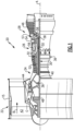
- FIG. 1 schematically illustrates a gas turbine engine 20.
- the gas turbine engine 20 is disclosed herein as a two-spool turbofan that generally incorporates a fan section 22, a compressor section 24, a combustor section 26 and a turbine section 28.
- Alternative engines might include an augmentor section (not shown) among other systems or features.
- the fan section 22 drives air along a bypass flow path B in a bypass duct defined within a nacelle 15, and also drives air along a core flow path C for compression and communication into the combustor section 26 then expansion through the turbine section 28.
- the exemplary engine 20 generally includes a low speed spool 30 and a high speed spool 32 mounted for rotation about an engine central longitudinal axis A relative to an engine static structure 36 via several bearing systems 38. It should be understood that various bearing systems 38 at various locations may alternatively or additionally be provided, and the location of bearing systems 38 may be varied as appropriate to the application.
- the low speed spool 30 generally includes an inner shaft 40 that interconnects a fan 42, a first (or low) pressure compressor 44 and a first (or low) pressure turbine 46.
- the inner shaft 40 is connected to the fan 42 through a speed change mechanism, which in exemplary gas turbine engine 20 is illustrated as a geared architecture 48 to drive the fan 42 at a lower speed than the low speed spool 30.
- the high speed spool 32 includes an outer shaft 50 that interconnects a second (or high) pressure compressor 52 and a second (or high) pressure turbine 54.
- a combustor 56 is arranged in exemplary gas turbine 20 between the high pressure compressor 52 and the high pressure turbine 54.
- a mid-turbine frame 57 of the engine static structure 36 is arranged generally between the high pressure turbine 54 and the low pressure turbine 46.
- the mid-turbine frame 57 further supports bearing systems 38 in the turbine section 28.
- the inner shaft 40 and the outer shaft 50 are concentric and rotate via bearing systems 38 about the engine central longitudinal axis A which is collinear with their longitudinal axes.
- the core airflow is compressed by the low pressure compressor 44 then the high pressure compressor 52, mixed and burned with fuel in the combustor 56, then expanded over the high pressure turbine 54 and low pressure turbine 46.
- the mid-turbine frame 57 includes airfoils 59 which are in the core airflow path C.
- the turbines 46, 54 rotationally drive the respective low speed spool 30 and high speed spool 32 in response to the expansion.
- gear system 48 may be located aft of combustor section 26 or even aft of turbine section 28, and fan section 22 may be positioned forward or aft of the location of gear system 48.
- the engine 20 in one example is a high-bypass geared aircraft engine.
- the engine 20 bypass ratio is greater than about six, with an example embodiment being greater than about ten
- the geared architecture 48 is an epicyclic gear train, such as a planetary gear system or other gear system, with a gear reduction ratio of greater than about 2.3 and the low pressure turbine 46 has a pressure ratio that is greater than about five.
- the engine 20 bypass ratio is greater than about ten
- the fan diameter is significantly larger than that of the low pressure compressor 44
- the low pressure turbine 46 has a pressure ratio that is greater than about five.
- Low pressure turbine 46 pressure ratio is pressure measured prior to inlet of low pressure turbine 46 as related to the pressure at the outlet of the low pressure turbine 46 prior to an exhaust nozzle.
- the geared architecture 48 may be an epicycle gear train, such as a planetary gear system or other gear system, with a gear reduction ratio of greater than about 2.3:1. It should be understood, however, that the above parameters are only exemplary of one embodiment of a geared architecture engine and that the present invention is applicable to other gas turbine engines including direct drive turbofans.
- the fan section 22 of the engine 20 is designed for a particular flight condition -- typically cruise at about 0.8 Mach and about 35,000 feet (10,668 meters).
- the flight condition of 0.8 Mach and 35,000 ft (10,668 meters), with the engine at its best fuel consumption - also known as "bucket cruise Thrust Specific Fuel Consumption ('TSFC')" - is the industry standard parameter of lbm of fuel being burned divided by lbf of thrust the engine produces at that minimum point.
- "Low fan pressure ratio” is the pressure ratio across the fan blade alone, without a Fan Exit Guide Vane (“FEGV”) system.
- the low fan pressure ratio as disclosed herein according to one non-limiting embodiment is less than about 1.45.
- the "Low corrected fan tip speed” as disclosed herein according to one non-limiting embodiment is less than about 1150 ft / second (350.5 meters/second).
- Figure 2 schematically illustrates a turbine vane 100 for inclusion in the turbine section 28 of the gas turbine engine 20.
- the turbine vane 100 includes a radially inner platform 120 and a radially outer platform 130.
- An airfoil 140 spans the platforms 120, 130.
- the airfoil 140 includes a pressure side 150 and a suction side (hidden) that join a leading edge 170 to a trailing edge 180.
- the suction side is opposite the pressure side 150.
- a cooling fluid is passed through a minicore cooling circuit 190 positioned within the suction side wall and/or the pressure side wall 150.
- the cooling circuit 190 is additionally positioned in at least one of the platforms 120, 130.
- a minicore cooling circuit refers to passages or channels that are cast into a wall of a structure and provide a cooling circuit.
- the minicore cooling circuits 190 are connected to at least one other of the minicore cooling circuits 190 to create a single completed cooling circuit within the walls of the vane 100.
- multiple distinct minicore cooling circuits 190 can be formed.
- the pressure side wall 150, the suction side wall, and the walls of the platforms 120, 130 are cast as thin as is mechanically feasible.
- film cooling holes 192 are included in some examples.
- the film cooling holes 192 provide a connection between internal passages of the minicore cooling circuit 190 and the exterior surface of the airfoil 140.
- the film cooling holes 192 expel coolant gasses from the minicore cooling circuit 190 along the surfaces of the vane 140 to generate a film cooling effect according to known film cooling techniques.
- One method for manufacturing the minicore cooling circuits 190 is via the utilization of investment casting.
- investment casting a core made of a destructible material is created and inserted into the mold prior to casting a component.
- the core is shaped in a negative three dimensional image (negative space) of the minicore cooling circuit 190 being cast within the part.
- the core is destroyed, and the remnants of the core are removed from the cast component via mechanical means, chemical means, or a combination of mechanical and chemical means.
- certain features are limited in dimension based on the dimensional tolerances or physical accessibility of the casting process.
- the film cooling holes 192 are one such feature. Due to limitations in investment casting processes, the film cooling holes 192 cannot be created in the right orientation for some applications.
- some exemplary manufacturing processes cast a component 100 without the film cooling holes 192, and incorporate the film cooling holes 192 as part of a finishing process.
- the film cooling holes 192 can be incorporated by drilling, electrical discharge machining (EDM), laser drilling, or any similar material removal process.
- the minicore cooling circuit 190 includes expanded plenums positioned at the location of the corresponding film cooling hole 192.
- Figure 3A (outside the wording of the claims) schematically illustrates a wall section 200 of a turbine vane. While illustrated as a portion of the pressure side wall 150, one of skill in the art will understand that the segment is representative of any type of component and could be a segment of any gaspath component including vanes, blade outer air seals, platforms, and the like.
- the segment 200 is drawn through the pressure side wall 150, and includes a minicore cooling circuit 290.
- the minicore cooling circuit 290 is positioned between an exterior surface of the pressure side wall 150, referred to as a hot side surface 211, and an interior surface of the pressure side wall 150, referred to as a cold side surface 212.
- Cold air 213, or another cooling gas is fed into the minicore cooling circuit 290 through one or more impingement feed holes 214 positioned on the cold side surface 212.
- the impingement feed holes 214 are cast holes that are manufactured using an investment casting technique, such as the technique described above.
- the cold air 213 flows through the minicore cooling circuit 290 and into a leading edge cooling plenum 216.
- the cooling plenum 216 operates to turn the cooling air 213, and allows the cooling air 213 to exit film cooling holes 217 in a desired direction.
- the cooling plenum 216 is defined by a thickness 220 normal to the hot side surface 211 that is larger than a thickness 221 of the remainder of the minicore cooling circuit 290 normal to the hot side surface 211.
- a corresponding thickness of the pressure side wall 250 at the location of the plenum 216 is further increased to accommodate the plenum 216.
- the thickness of the entire wall can be cast sufficient to accommodate the plenum 216, despite the plenum 216 only being present at certain positions.
- the plenum 216 In addition to the plenum 216 providing sufficient thickness to allow drilling, EDM, or other post casting manufacturing methods to create film cooling holes 217 that connected the minicore cooling circuit 290 with the hot side surface 211, the plenum 216 also allows for the redirection of the cooling air 213. Absent the plenum 216, the cooling air 213 travels through minicore cooling circuit in a first direction, and the air exiting the minicore cooling circuit 290 is required to flow in generally the same direction due to the flow rate of the fluid passing through the minicore cooling circuit 290. By incorporating the plenum 216 at the film cooling hole 217, the flow 213 can be reversed, and the cooling flow 213 exits the minicore cooling circuit 290 in approximately the opposite direction of the flow 213 through the minicore 290.
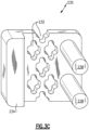
- Figures 3B and 3C illustrate a portion of an investment casting core 230 from a hot side view ( Figure 3B ) and a cold side view ( Figure 3C ).
- the investment casting core 230 is constructed of a solid destructible material, and defines a negative space of the minicore cooling circuit 290. Multiple openings 232 define positions where internal posts within the minicore cooling circuit 290 will be located.
- a thicker section 234 defines the geometry of the plenum 216, and extends an entire radial height of the minicore cooling circuit 290. In alternative examples where the gaspath component is not radially aligned, such as blade outer air seals, and platforms, the thicker section 234 extends an entire length of the minicore cooling circuit approximately normal to a general direction of fluid flow through the minicore circuit 290.
- FIG. 4A schematically illustrates a cut out wall portion 300 of a gaspath component including film cooling holes 317 connected at a fluid input end 392 as well as at a fluid output end 394 of a minicore 390 according to one example.
- the segment 300 is drawn through the pressure side wall 150, and includes a minicore cooling circuit 390.
- the minicore cooling circuit 390 is positioned between a hot side wall 311, and a cold side wall 312.
- Cold air 313, or another cooling gas is fed into the mini core cooling circuit 390 through one or more impingement feed holes 314 positioned on the cold side 312 into a trailing edge plenum 319.
- the impingement feed holes 314 are cast holes that are manufactured using an investment casting technique, such as the technique described above.
- the cold air 313 flows through the minicore cooling circuit 390 and into a leading edge cooling plenum 316.
- the leading edge cooling plenum 316 operates to turn the cooling air 313, and allows the cooling air 313 to exit film cooling holes 317 oriented in a downstream direction.
- the leading edge cooling plenum 316 is defined by a thickness 320 normal to the hot side surface 311 that is larger than a thickness 321 of the majority of the minicore cooling circuit 390 normal to the hot side surface 311.
- the trailing edge plenum 319 is defined by a thickness 323 normal to the hot side surface 311 that is larger than a thickness 321 of the majority of the minicore cooling circuit 390.
- the thickness 320 of the leading edge plenum 316 and the thickness 323 of the trailing edge plenum 319 are the same.
- the plenums 316, 319 could be varied and still fall within the present disclosure.
- the plenums 316, 319 are referred to by the edge to which they are most proximate, and the plenums 316, 319 may not actually be at the leading edge 170 or trailing edge 180 of the component 100 including the segment 300.
- a corresponding thickness of the pressure side wall 350 at the location of the plenums 316, 319 is further increased to accommodate the plenums 316, 319.
- the thickness of the entire wall can be cast sufficient to accommodate the plenums 316, 319, despite the plenums 316, 319 only being present at certain positions.
- the trailing edge plenum 319 provides sufficient thickness in the wall for the cooling holes 317 to be drilled, machined, or otherwise connected to the plenum 319 in a post casting manufacturing process.
- the fluid entering the minicore circuit 390 at the trailing edge plenum 319 is traveling at approximately the same direction as the cooling holes 317, no turning is required in the trailing edge plenum 319.
- the leading edge plenum 316 operates in a fundamentally similar manner, and provides the same benefits, as the leading edge plenum 216 of Figure 3A .
- Figures 4B and 4C illustrate a portion of an investment casting core 330 from a hot side view ( Figure 3B ) and a cold side view ( Figure 3C ).
- the investment casting core 330 is constructed of a solid destructible material, and defines a negative space of the minicore cooling circuit 390. Multiple openings 332 define positions where internal structures of the minicore cooling circuit 390 will be located. Thicker sections 334, 336 define the geometry of the plenums 316, 319 and extend an entire radial height of the minicore circuit 390.
- the thicker sections 334, 336 extends an entire length of the minicore cooling circuit 390 approximately normal to a general direction of fluid flow through the minicore cooling circuit 390. Also included in the investment casting core 330 are multiple posts 338 that define a negative space of the impingement holes 314 which allow cooling fluid into the minicore circuit 390.
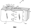
- FIG. 5 (outside the wording of the claims) schematically illustrates a cut out wall portion 400 of a gaspath component including film cooling holes 417 connected to a minicore cooling circuit 490 at a fluid input end 492 according to one example. Also included in the example is a cast opening 494 at a trailing edge end of the minicore cooling circuit 490.
- the cooling fluid enters the minicore cooling circuit 490 through impingement holes 414 into a leading edge plenum 418.
- the cooling fluid 413 passes through the minicore cooling circuit 490 to the trailing edge exit 494.
- leading edge plenum 418 Also connected to the leading edge plenum 418 are multiple film cooling holes 417, each of which is incorporated into the segment 400 after casting using known material removal techniques. In order to facilitate the film cooling holes 417, the leading edge plenum 418 is thicker than a remainder of the minicore cooling circuit 490 normal to a hot side 411 of the wall.
- the segments 200, 300, 400 can be distinct segments of a single gaspath component, or can be included in any combination in a single gaspath component.
- the disclosed minicores can, in some examples, be refractory metal cores (RMCs). In alternative examples the minicores can be alternative constructions.
Landscapes
- Engineering & Computer Science (AREA)
- Mechanical Engineering (AREA)
- General Engineering & Computer Science (AREA)
- Architecture (AREA)
- Turbine Rotor Nozzle Sealing (AREA)
Claims (11)
- Turbinentriebwerkskomponente (100), umfassend:eine Wand (150), die sich von einer Anströmkante (170) zu einer Abströmkante (180) erstreckt, wobei die Wand (150) eine heiße Seitenfläche (311), die im eingebauten Zustand einem Gasstrom zugewandt ist, und eine kalte Seitenfläche (312) gegenüber der heißen Seitenfläche (311) beinhaltet;mindestens einen Minikern-Kühlkreislauf (190; 390), der zwischen der heißen Seitenfläche (311) und der kalten Seitenfläche (312) innerhalb der Wand (150) angeordnet ist;mindestens einen Kühlfluideinlass (314) zum Verbinden eines Abströmkantenplenums (391) des mindestens einen Minikern-Kühlkreislaufs (190; 390) mit einer Kühlmittelquelle, wobei der mindestens eine Kühlfluideinlass (314) mindestens ein Aufprallkühlfluid-Einlass (314) ist; undeine Vielzahl von Filmkühllöchern (317), die den mindestens einen Minikern-Kühlkreislauf (190; 390) mit der heißen Seitenfläche (311) verbindet, wobei der mindestens eine Minikern-Kühlkreislauf (190; 390) ein Anströmkantenplenum (316) mit einer Dicke (320) senkrecht zu der heißen Seitenfläche (311) beinhaltet, die größer ist als eine Dicke (321) des Großteils des mindestens einen Minikern-Kühlkreislaufs (190; 390) senkrecht zu der heißen Seitenfläche (311), wobei das Anströmkantenplenum (316; 418) ein Abschnitt des mindestens einen Minikern-Kühlkreislaufs (190; 390) ist, der der Anströmkante (170) am nächsten liegt, wobei das Anströmkantenplenum (316) dazu konfiguriert ist, eine Strömungsrichtung eines Kühlmittels (313), das durch den mindestens einen Minikern-Kühlkreislauf (190; 390) fließt, umzukehren, wobei das Abströmkantenplenum (319) eine Dicke (323) senkrecht zu der heißen Seitenfläche (311) aufweist, die größer ist als eine Dicke (321) des Großteils des mindestens einen Minikern-Kühlkreislaufs (390) senkrecht zu der heißen Seitenfläche (311), wobei das Abströmkantenplenum (319) ein Abschnitt des mindestens einen Minikern-Kühlkreislaufs (390) ist, der der Abströmkante (180) am nächsten liegt, wobei mindestens eines der Filmkühllöcher (317) das Anströmkantenplenum (316, 319) mit der heißen Seitenfläche (311) verbindet, dadurch gekennzeichnet, dass:
mindestens ein weiteres der Filmkühllöcher (317) das Abströmkantenplenum (316, 319) mit der heißen Seitenfläche (311) verbindet. - Turbinentriebwerkskomponente (100) nach Anspruch 1, wobei das Abströmkantenplenum (319) an dem mindestens einen Kühlfluideinlass (314; 414) positioniert ist.
- Turbinentriebwerkskomponente (100) nach Anspruch 1 oder 2, wobei die Dicke (323) des Abströmkantenplenums (319) und die Dicke (320) des Anströmkantenplenums (316) gleich sind.
- Turbinentriebwerkskomponente (100) nach Anspruch 1 oder 2, wobei die Dicke (323) des Abströmkantenplenums (319) und die Dicke (320) des Anströmkantenplenums (316) unterschiedlich sind.
- Turbinentriebwerkskomponente (100) nach einem der vorhergehenden Ansprüche, wobei ein Auslass (494) des mindestens einen Minikern-Kühlkreislaufs (490) mit der Abströmkante (180) der Komponente (100) verbunden ist.
- Turbinentriebwerkskomponente (100) nach einem der vorhergehenden Ansprüche, wobei ein oder der Auslass (494) des mindestens einen Minikern-Kühlkreislaufs (490) mit der Anströmkante (170) der Komponente (100) verbunden ist.
- Turbinentriebwerkskomponente (100) nach einem der vorhergehenden Ansprüche, wobei eine Dicke der Wand (150) senkrecht zu der heißen Seitenfläche (311) entlang einer Länge des mindestens einen Minikern-Kühlkreislaufs (190; 390) ungefähr gleich ist.
- Turbinentriebwerkskomponente (100) nach einem der vorhergehenden Ansprüche, wobei eine Dicke der Wand (150) senkrecht zu der heißen Seitenfläche (311) an dem Anström- und/oder Abströmkantenplenum (316, 319) größer ist als eine Dicke der Wand (150) senkrecht zu der heißen Seitenfläche (311) entlang eines Rests des mindestens einen Minikern-Kühlkreislaufs (190; 390).
- Turbinentriebwerkskomponente (100) nach einem der vorhergehenden Ansprüche, wobei der mindestens eine Minikern-Kühlkreislauf (190; 390) ein mit Feinguss hergestellter Hohlraum ist und die Filmkühllöcher (317) ein Produkt eines Endbearbeitungsprozesses sind.
- Turbinentriebwerkskomponente (100) nach Anspruch 9, wobei der Endbearbeitungsprozess mindestens eines von elektrischer Entladungsbearbeitung, Laserbohren und Bohren ist.
- Turbinentriebwerkskomponente (100) nach einem der vorhergehenden Ansprüche, wobei der mindestens eine Minikern-Kühlkreislauf (190; 390) mindestens einen hitzebeständigen Metallkern (refractory metal core- RMC) beinhaltet.
Priority Applications (1)
| Application Number | Priority Date | Filing Date | Title |
|---|---|---|---|
| EP24196021.0A EP4442961A3 (de) | 2017-06-22 | 2018-06-21 | Gaswegkomponente mit minikernplenums |
Applications Claiming Priority (1)
| Application Number | Priority Date | Filing Date | Title |
|---|---|---|---|
| US15/629,812 US10808571B2 (en) | 2017-06-22 | 2017-06-22 | Gaspath component including minicore plenums |
Related Child Applications (1)
| Application Number | Title | Priority Date | Filing Date |
|---|---|---|---|
| EP24196021.0A Division EP4442961A3 (de) | 2017-06-22 | 2018-06-21 | Gaswegkomponente mit minikernplenums |
Publications (2)
| Publication Number | Publication Date |
|---|---|
| EP3418495A1 EP3418495A1 (de) | 2018-12-26 |
| EP3418495B1 true EP3418495B1 (de) | 2024-08-28 |
Family
ID=62748872
Family Applications (2)
| Application Number | Title | Priority Date | Filing Date |
|---|---|---|---|
| EP24196021.0A Pending EP4442961A3 (de) | 2017-06-22 | 2018-06-21 | Gaswegkomponente mit minikernplenums |
| EP18179169.0A Active EP3418495B1 (de) | 2017-06-22 | 2018-06-21 | Gasstromvorrichtung mit minikernplenen |
Family Applications Before (1)
| Application Number | Title | Priority Date | Filing Date |
|---|---|---|---|
| EP24196021.0A Pending EP4442961A3 (de) | 2017-06-22 | 2018-06-21 | Gaswegkomponente mit minikernplenums |
Country Status (2)
| Country | Link |
|---|---|
| US (1) | US10808571B2 (de) |
| EP (2) | EP4442961A3 (de) |
Families Citing this family (1)
| Publication number | Priority date | Publication date | Assignee | Title |
|---|---|---|---|---|
| US11486257B2 (en) * | 2019-05-03 | 2022-11-01 | Raytheon Technologies Corporation | Cooling passage configuration |
Citations (2)
| Publication number | Priority date | Publication date | Assignee | Title |
|---|---|---|---|---|
| US5383766A (en) * | 1990-07-09 | 1995-01-24 | United Technologies Corporation | Cooled vane |
| US20060222494A1 (en) * | 2005-03-29 | 2006-10-05 | Siemens Westinghouse Power Corporation | Turbine blade leading edge cooling system |
Family Cites Families (36)
| Publication number | Priority date | Publication date | Assignee | Title |
|---|---|---|---|---|
| US3542486A (en) * | 1968-09-27 | 1970-11-24 | Gen Electric | Film cooling of structural members in gas turbine engines |
| US5405242A (en) * | 1990-07-09 | 1995-04-11 | United Technologies Corporation | Cooled vane |
| US5626462A (en) | 1995-01-03 | 1997-05-06 | General Electric Company | Double-wall airfoil |
| US6213714B1 (en) | 1999-06-29 | 2001-04-10 | Allison Advanced Development Company | Cooled airfoil |
| US6254334B1 (en) * | 1999-10-05 | 2001-07-03 | United Technologies Corporation | Method and apparatus for cooling a wall within a gas turbine engine |
| DE10001109B4 (de) | 2000-01-13 | 2012-01-19 | Alstom Technology Ltd. | Gekühlte Schaufel für eine Gasturbine |
| US6981846B2 (en) * | 2003-03-12 | 2006-01-03 | Florida Turbine Technologies, Inc. | Vortex cooling of turbine blades |
| US7217092B2 (en) | 2004-04-14 | 2007-05-15 | General Electric Company | Method and apparatus for reducing turbine blade temperatures |
| US7118326B2 (en) | 2004-06-17 | 2006-10-10 | Siemens Power Generation, Inc. | Cooled gas turbine vane |
| US7344197B2 (en) * | 2004-07-30 | 2008-03-18 | Brian Matthew Sanderson | Rollable supporting device |
| US7185695B1 (en) * | 2005-09-01 | 2007-03-06 | United Technologies Corporation | Investment casting pattern manufacture |
| US7744347B2 (en) * | 2005-11-08 | 2010-06-29 | United Technologies Corporation | Peripheral microcircuit serpentine cooling for turbine airfoils |
| US7311498B2 (en) * | 2005-11-23 | 2007-12-25 | United Technologies Corporation | Microcircuit cooling for blades |
| US7600966B2 (en) | 2006-01-17 | 2009-10-13 | United Technologies Corporation | Turbine airfoil with improved cooling |
| US7695246B2 (en) * | 2006-01-31 | 2010-04-13 | United Technologies Corporation | Microcircuits for small engines |
| US20100247328A1 (en) * | 2006-06-06 | 2010-09-30 | United Technologies Corporation | Microcircuit cooling for blades |
| US7520723B2 (en) * | 2006-07-07 | 2009-04-21 | Siemens Energy, Inc. | Turbine airfoil cooling system with near wall vortex cooling chambers |
| US7527474B1 (en) * | 2006-08-11 | 2009-05-05 | Florida Turbine Technologies, Inc. | Turbine airfoil with mini-serpentine cooling passages |
| US7866948B1 (en) * | 2006-08-16 | 2011-01-11 | Florida Turbine Technologies, Inc. | Turbine airfoil with near-wall impingement and vortex cooling |
| US7717676B2 (en) * | 2006-12-11 | 2010-05-18 | United Technologies Corporation | High aspect ratio blade main core modifications for peripheral serpentine microcircuits |
| US7731481B2 (en) | 2006-12-18 | 2010-06-08 | United Technologies Corporation | Airfoil cooling with staggered refractory metal core microcircuits |
| US7862299B1 (en) * | 2007-03-21 | 2011-01-04 | Florida Turbine Technologies, Inc. | Two piece hollow turbine blade with serpentine cooling circuits |
| US8202054B2 (en) * | 2007-05-18 | 2012-06-19 | Siemens Energy, Inc. | Blade for a gas turbine engine |
| US8070441B1 (en) * | 2007-07-20 | 2011-12-06 | Florida Turbine Technologies, Inc. | Turbine airfoil with trailing edge cooling channels |
| US7815414B2 (en) * | 2007-07-27 | 2010-10-19 | United Technologies Corporation | Airfoil mini-core plugging devices |
| US8297927B1 (en) * | 2008-03-04 | 2012-10-30 | Florida Turbine Technologies, Inc. | Near wall multiple impingement serpentine flow cooled airfoil |
| US8251660B1 (en) * | 2009-10-26 | 2012-08-28 | Florida Turbine Technologies, Inc. | Turbine airfoil with near wall vortex cooling |
| US8944141B2 (en) * | 2010-12-22 | 2015-02-03 | United Technologies Corporation | Drill to flow mini core |
| US8915289B2 (en) * | 2011-05-10 | 2014-12-23 | Howmet Corporation | Ceramic core with composite insert for casting airfoils |
| JP6093441B2 (ja) | 2012-05-31 | 2017-03-08 | ゼネラル・エレクトリック・カンパニイ | 翼冷却回路 |
| US9551228B2 (en) * | 2013-01-09 | 2017-01-24 | United Technologies Corporation | Airfoil and method of making |
| SG11201505736UA (en) * | 2013-02-14 | 2015-08-28 | United Technologies Corp | Gas turbine engine component having surface indicator |
| US20160222794A1 (en) | 2013-09-09 | 2016-08-04 | United Technologies Corporation | Incidence tolerant engine component |
| US9938899B2 (en) | 2015-06-15 | 2018-04-10 | General Electric Company | Hot gas path component having cast-in features for near wall cooling |
| US10024190B1 (en) | 2015-11-02 | 2018-07-17 | Florida Turbine Technologies, Inc. | Apparatus and process for forming an air cooled turbine airfoil with a cooling air channel and discharge slot in a thin wall |
| US10358928B2 (en) | 2016-05-10 | 2019-07-23 | General Electric Company | Airfoil with cooling circuit |
-
2017
- 2017-06-22 US US15/629,812 patent/US10808571B2/en active Active
-
2018
- 2018-06-21 EP EP24196021.0A patent/EP4442961A3/de active Pending
- 2018-06-21 EP EP18179169.0A patent/EP3418495B1/de active Active
Patent Citations (2)
| Publication number | Priority date | Publication date | Assignee | Title |
|---|---|---|---|---|
| US5383766A (en) * | 1990-07-09 | 1995-01-24 | United Technologies Corporation | Cooled vane |
| US20060222494A1 (en) * | 2005-03-29 | 2006-10-05 | Siemens Westinghouse Power Corporation | Turbine blade leading edge cooling system |
Also Published As
| Publication number | Publication date |
|---|---|
| US20180371941A1 (en) | 2018-12-27 |
| EP4442961A2 (de) | 2024-10-09 |
| EP4442961A3 (de) | 2025-01-22 |
| EP3418495A1 (de) | 2018-12-26 |
| US10808571B2 (en) | 2020-10-20 |
Similar Documents
| Publication | Publication Date | Title |
|---|---|---|
| US11035236B2 (en) | Baffle for a component of a gas turbine engine | |
| EP3063389B1 (de) | Bohrungsgekühlte filmspendende sockel | |
| US10465542B2 (en) | Gas turbine engine turbine vane baffle and serpentine cooling passage | |
| EP3044418B1 (de) | Gasturbinenmotorschaufel mit gabelförmigem blechkühlsystem | |
| EP3034793B1 (de) | Gasturbinenmotorkomponente mit erhöhter kühlleistung | |
| EP2956646B1 (de) | Bauteil für ein gasturbinentriebwerk und zugehöriges verfahren zur formung eines kühllochs | |
| EP3536903B1 (de) | Kühlkanal mit strukturrippe und filmkühlschlitz | |
| EP3078807B2 (de) | Kühlkanäle für eine gasturbinenmotorkomponente | |
| US10801344B2 (en) | Double wall turbine gas turbine engine vane with discrete opposing skin core cooling configuration | |
| US11286793B2 (en) | Airfoil with ribs having connector arms and apertures defining a cooling circuit | |
| EP2948634B1 (de) | Gasturbinenmotorkomponente mit prallkühlung mittels einer abgewinkelten öffnung | |
| US20170002662A1 (en) | Gas turbine engine airfoil with bi-axial skin core | |
| US11828193B2 (en) | Vane core assemblies and methods | |
| US10808571B2 (en) | Gaspath component including minicore plenums | |
| US10801333B2 (en) | Airfoils, cores, and methods of manufacture for forming airfoils having fluidly connected platform cooling circuits | |
| EP3822454B1 (de) | Schaufel mit verbindungsrippe | |
| US11180998B2 (en) | Airfoil with skincore passage resupply | |
| US11028700B2 (en) | Airfoil with cooling passage circuit through platforms and airfoil section | |
| EP3450697B1 (de) | Leitschaufelsegment und zugehöriges gasturbinentriebwerk | |
| EP3656983A1 (de) | Wärmegradientenverringerungsvorrichtung für gasturbinenmotorkomponente | |
| US12215601B2 (en) | Air foil with staggered cooling hole configuration | |
| US20160160652A1 (en) | Cooled pocket in a turbine vane platform | |
| EP3581762B1 (de) | Kühlkanalanordnung für gasturbinendeckband |
Legal Events
| Date | Code | Title | Description |
|---|---|---|---|
| PUAI | Public reference made under article 153(3) epc to a published international application that has entered the european phase |
Free format text: ORIGINAL CODE: 0009012 |
|
| STAA | Information on the status of an ep patent application or granted ep patent |
Free format text: STATUS: THE APPLICATION HAS BEEN PUBLISHED |
|
| AK | Designated contracting states |
Kind code of ref document: A1 Designated state(s): AL AT BE BG CH CY CZ DE DK EE ES FI FR GB GR HR HU IE IS IT LI LT LU LV MC MK MT NL NO PL PT RO RS SE SI SK SM TR |
|
| AX | Request for extension of the european patent |
Extension state: BA ME |
|
| STAA | Information on the status of an ep patent application or granted ep patent |
Free format text: STATUS: REQUEST FOR EXAMINATION WAS MADE |
|
| 17P | Request for examination filed |
Effective date: 20190626 |
|
| RBV | Designated contracting states (corrected) |
Designated state(s): AL AT BE BG CH CY CZ DE DK EE ES FI FR GB GR HR HU IE IS IT LI LT LU LV MC MK MT NL NO PL PT RO RS SE SI SK SM TR |
|
| STAA | Information on the status of an ep patent application or granted ep patent |
Free format text: STATUS: EXAMINATION IS IN PROGRESS |
|
| RAP1 | Party data changed (applicant data changed or rights of an application transferred) |
Owner name: RAYTHEON TECHNOLOGIES CORPORATION |
|
| R17P | Request for examination filed (corrected) |
Effective date: 20190626 |
|
| 17Q | First examination report despatched |
Effective date: 20210323 |
|
| RAP3 | Party data changed (applicant data changed or rights of an application transferred) |
Owner name: RTX CORPORATION |
|
| GRAP | Despatch of communication of intention to grant a patent |
Free format text: ORIGINAL CODE: EPIDOSNIGR1 |
|
| STAA | Information on the status of an ep patent application or granted ep patent |
Free format text: STATUS: GRANT OF PATENT IS INTENDED |
|
| INTG | Intention to grant announced |
Effective date: 20240318 |
|
| GRAS | Grant fee paid |
Free format text: ORIGINAL CODE: EPIDOSNIGR3 |
|
| GRAA | (expected) grant |
Free format text: ORIGINAL CODE: 0009210 |
|
| STAA | Information on the status of an ep patent application or granted ep patent |
Free format text: STATUS: THE PATENT HAS BEEN GRANTED |
|
| AK | Designated contracting states |
Kind code of ref document: B1 Designated state(s): AL AT BE BG CH CY CZ DE DK EE ES FI FR GB GR HR HU IE IS IT LI LT LU LV MC MK MT NL NO PL PT RO RS SE SI SK SM TR |
|
| REG | Reference to a national code |
Ref country code: GB Ref legal event code: FG4D |
|
| REG | Reference to a national code |
Ref country code: CH Ref legal event code: EP |
|
| REG | Reference to a national code |
Ref country code: DE Ref legal event code: R096 Ref document number: 602018073556 Country of ref document: DE |
|
| REG | Reference to a national code |
Ref country code: IE Ref legal event code: FG4D |
|
| REG | Reference to a national code |
Ref country code: LT Ref legal event code: MG9D |
|
| PG25 | Lapsed in a contracting state [announced via postgrant information from national office to epo] |
Ref country code: NO Free format text: LAPSE BECAUSE OF FAILURE TO SUBMIT A TRANSLATION OF THE DESCRIPTION OR TO PAY THE FEE WITHIN THE PRESCRIBED TIME-LIMIT Effective date: 20241128 |
|
| REG | Reference to a national code |
Ref country code: AT Ref legal event code: MK05 Ref document number: 1718128 Country of ref document: AT Kind code of ref document: T Effective date: 20240828 |
|
| PG25 | Lapsed in a contracting state [announced via postgrant information from national office to epo] |
Ref country code: PL Free format text: LAPSE BECAUSE OF FAILURE TO SUBMIT A TRANSLATION OF THE DESCRIPTION OR TO PAY THE FEE WITHIN THE PRESCRIBED TIME-LIMIT Effective date: 20240828 Ref country code: NL Free format text: LAPSE BECAUSE OF FAILURE TO SUBMIT A TRANSLATION OF THE DESCRIPTION OR TO PAY THE FEE WITHIN THE PRESCRIBED TIME-LIMIT Effective date: 20240828 Ref country code: FI Free format text: LAPSE BECAUSE OF FAILURE TO SUBMIT A TRANSLATION OF THE DESCRIPTION OR TO PAY THE FEE WITHIN THE PRESCRIBED TIME-LIMIT Effective date: 20240828 Ref country code: PT Free format text: LAPSE BECAUSE OF FAILURE TO SUBMIT A TRANSLATION OF THE DESCRIPTION OR TO PAY THE FEE WITHIN THE PRESCRIBED TIME-LIMIT Effective date: 20241230 Ref country code: GR Free format text: LAPSE BECAUSE OF FAILURE TO SUBMIT A TRANSLATION OF THE DESCRIPTION OR TO PAY THE FEE WITHIN THE PRESCRIBED TIME-LIMIT Effective date: 20241129 |
|
| PG25 | Lapsed in a contracting state [announced via postgrant information from national office to epo] |
Ref country code: BG Free format text: LAPSE BECAUSE OF FAILURE TO SUBMIT A TRANSLATION OF THE DESCRIPTION OR TO PAY THE FEE WITHIN THE PRESCRIBED TIME-LIMIT Effective date: 20240828 |
|
| PG25 | Lapsed in a contracting state [announced via postgrant information from national office to epo] |
Ref country code: LV Free format text: LAPSE BECAUSE OF FAILURE TO SUBMIT A TRANSLATION OF THE DESCRIPTION OR TO PAY THE FEE WITHIN THE PRESCRIBED TIME-LIMIT Effective date: 20240828 |
|
| REG | Reference to a national code |
Ref country code: NL Ref legal event code: MP Effective date: 20240828 |
|
| PG25 | Lapsed in a contracting state [announced via postgrant information from national office to epo] |
Ref country code: AT Free format text: LAPSE BECAUSE OF FAILURE TO SUBMIT A TRANSLATION OF THE DESCRIPTION OR TO PAY THE FEE WITHIN THE PRESCRIBED TIME-LIMIT Effective date: 20240828 Ref country code: IS Free format text: LAPSE BECAUSE OF FAILURE TO SUBMIT A TRANSLATION OF THE DESCRIPTION OR TO PAY THE FEE WITHIN THE PRESCRIBED TIME-LIMIT Effective date: 20241228 |
|
| PG25 | Lapsed in a contracting state [announced via postgrant information from national office to epo] |
Ref country code: HR Free format text: LAPSE BECAUSE OF FAILURE TO SUBMIT A TRANSLATION OF THE DESCRIPTION OR TO PAY THE FEE WITHIN THE PRESCRIBED TIME-LIMIT Effective date: 20240828 |
|
| PG25 | Lapsed in a contracting state [announced via postgrant information from national office to epo] |
Ref country code: RS Free format text: LAPSE BECAUSE OF FAILURE TO SUBMIT A TRANSLATION OF THE DESCRIPTION OR TO PAY THE FEE WITHIN THE PRESCRIBED TIME-LIMIT Effective date: 20241128 Ref country code: ES Free format text: LAPSE BECAUSE OF FAILURE TO SUBMIT A TRANSLATION OF THE DESCRIPTION OR TO PAY THE FEE WITHIN THE PRESCRIBED TIME-LIMIT Effective date: 20240828 |
|
| PG25 | Lapsed in a contracting state [announced via postgrant information from national office to epo] |
Ref country code: RS Free format text: LAPSE BECAUSE OF FAILURE TO SUBMIT A TRANSLATION OF THE DESCRIPTION OR TO PAY THE FEE WITHIN THE PRESCRIBED TIME-LIMIT Effective date: 20241128 Ref country code: PT Free format text: LAPSE BECAUSE OF FAILURE TO SUBMIT A TRANSLATION OF THE DESCRIPTION OR TO PAY THE FEE WITHIN THE PRESCRIBED TIME-LIMIT Effective date: 20241230 Ref country code: PL Free format text: LAPSE BECAUSE OF FAILURE TO SUBMIT A TRANSLATION OF THE DESCRIPTION OR TO PAY THE FEE WITHIN THE PRESCRIBED TIME-LIMIT Effective date: 20240828 Ref country code: NO Free format text: LAPSE BECAUSE OF FAILURE TO SUBMIT A TRANSLATION OF THE DESCRIPTION OR TO PAY THE FEE WITHIN THE PRESCRIBED TIME-LIMIT Effective date: 20241128 Ref country code: NL Free format text: LAPSE BECAUSE OF FAILURE TO SUBMIT A TRANSLATION OF THE DESCRIPTION OR TO PAY THE FEE WITHIN THE PRESCRIBED TIME-LIMIT Effective date: 20240828 Ref country code: LV Free format text: LAPSE BECAUSE OF FAILURE TO SUBMIT A TRANSLATION OF THE DESCRIPTION OR TO PAY THE FEE WITHIN THE PRESCRIBED TIME-LIMIT Effective date: 20240828 Ref country code: IS Free format text: LAPSE BECAUSE OF FAILURE TO SUBMIT A TRANSLATION OF THE DESCRIPTION OR TO PAY THE FEE WITHIN THE PRESCRIBED TIME-LIMIT Effective date: 20241228 Ref country code: HR Free format text: LAPSE BECAUSE OF FAILURE TO SUBMIT A TRANSLATION OF THE DESCRIPTION OR TO PAY THE FEE WITHIN THE PRESCRIBED TIME-LIMIT Effective date: 20240828 Ref country code: GR Free format text: LAPSE BECAUSE OF FAILURE TO SUBMIT A TRANSLATION OF THE DESCRIPTION OR TO PAY THE FEE WITHIN THE PRESCRIBED TIME-LIMIT Effective date: 20241129 Ref country code: FI Free format text: LAPSE BECAUSE OF FAILURE TO SUBMIT A TRANSLATION OF THE DESCRIPTION OR TO PAY THE FEE WITHIN THE PRESCRIBED TIME-LIMIT Effective date: 20240828 Ref country code: ES Free format text: LAPSE BECAUSE OF FAILURE TO SUBMIT A TRANSLATION OF THE DESCRIPTION OR TO PAY THE FEE WITHIN THE PRESCRIBED TIME-LIMIT Effective date: 20240828 Ref country code: BG Free format text: LAPSE BECAUSE OF FAILURE TO SUBMIT A TRANSLATION OF THE DESCRIPTION OR TO PAY THE FEE WITHIN THE PRESCRIBED TIME-LIMIT Effective date: 20240828 Ref country code: AT Free format text: LAPSE BECAUSE OF FAILURE TO SUBMIT A TRANSLATION OF THE DESCRIPTION OR TO PAY THE FEE WITHIN THE PRESCRIBED TIME-LIMIT Effective date: 20240828 |
|
| PG25 | Lapsed in a contracting state [announced via postgrant information from national office to epo] |
Ref country code: RO Free format text: LAPSE BECAUSE OF FAILURE TO SUBMIT A TRANSLATION OF THE DESCRIPTION OR TO PAY THE FEE WITHIN THE PRESCRIBED TIME-LIMIT Effective date: 20240828 Ref country code: SM Free format text: LAPSE BECAUSE OF FAILURE TO SUBMIT A TRANSLATION OF THE DESCRIPTION OR TO PAY THE FEE WITHIN THE PRESCRIBED TIME-LIMIT Effective date: 20240828 Ref country code: DK Free format text: LAPSE BECAUSE OF FAILURE TO SUBMIT A TRANSLATION OF THE DESCRIPTION OR TO PAY THE FEE WITHIN THE PRESCRIBED TIME-LIMIT Effective date: 20240828 |
|
| PG25 | Lapsed in a contracting state [announced via postgrant information from national office to epo] |
Ref country code: EE Free format text: LAPSE BECAUSE OF FAILURE TO SUBMIT A TRANSLATION OF THE DESCRIPTION OR TO PAY THE FEE WITHIN THE PRESCRIBED TIME-LIMIT Effective date: 20240828 |
|
| PG25 | Lapsed in a contracting state [announced via postgrant information from national office to epo] |
Ref country code: CZ Free format text: LAPSE BECAUSE OF FAILURE TO SUBMIT A TRANSLATION OF THE DESCRIPTION OR TO PAY THE FEE WITHIN THE PRESCRIBED TIME-LIMIT Effective date: 20240828 |
|
| PG25 | Lapsed in a contracting state [announced via postgrant information from national office to epo] |
Ref country code: SK Free format text: LAPSE BECAUSE OF FAILURE TO SUBMIT A TRANSLATION OF THE DESCRIPTION OR TO PAY THE FEE WITHIN THE PRESCRIBED TIME-LIMIT Effective date: 20240828 Ref country code: IT Free format text: LAPSE BECAUSE OF FAILURE TO SUBMIT A TRANSLATION OF THE DESCRIPTION OR TO PAY THE FEE WITHIN THE PRESCRIBED TIME-LIMIT Effective date: 20240828 |
|
| REG | Reference to a national code |
Ref country code: DE Ref legal event code: R097 Ref document number: 602018073556 Country of ref document: DE |
|
| PLBE | No opposition filed within time limit |
Free format text: ORIGINAL CODE: 0009261 |
|
| STAA | Information on the status of an ep patent application or granted ep patent |
Free format text: STATUS: NO OPPOSITION FILED WITHIN TIME LIMIT |
|
| PGFP | Annual fee paid to national office [announced via postgrant information from national office to epo] |
Ref country code: DE Payment date: 20250520 Year of fee payment: 8 |
|
| PGFP | Annual fee paid to national office [announced via postgrant information from national office to epo] |
Ref country code: GB Payment date: 20250520 Year of fee payment: 8 |
|
| PGFP | Annual fee paid to national office [announced via postgrant information from national office to epo] |
Ref country code: FR Payment date: 20250521 Year of fee payment: 8 |
|
| 26N | No opposition filed |
Effective date: 20250530 |
|
| PG25 | Lapsed in a contracting state [announced via postgrant information from national office to epo] |
Ref country code: SE Free format text: LAPSE BECAUSE OF FAILURE TO SUBMIT A TRANSLATION OF THE DESCRIPTION OR TO PAY THE FEE WITHIN THE PRESCRIBED TIME-LIMIT Effective date: 20240828 |
|
| REG | Reference to a national code |
Ref country code: CH Ref legal event code: H13 Free format text: ST27 STATUS EVENT CODE: U-0-0-H10-H13 (AS PROVIDED BY THE NATIONAL OFFICE) Effective date: 20260127 |
|
| PG25 | Lapsed in a contracting state [announced via postgrant information from national office to epo] |
Ref country code: MC Free format text: LAPSE BECAUSE OF FAILURE TO SUBMIT A TRANSLATION OF THE DESCRIPTION OR TO PAY THE FEE WITHIN THE PRESCRIBED TIME-LIMIT Effective date: 20240828 |
|
| PG25 | Lapsed in a contracting state [announced via postgrant information from national office to epo] |
Ref country code: LU Free format text: LAPSE BECAUSE OF NON-PAYMENT OF DUE FEES Effective date: 20250621 |
|
| REG | Reference to a national code |
Ref country code: BE Ref legal event code: MM Effective date: 20250630 |
|
| PG25 | Lapsed in a contracting state [announced via postgrant information from national office to epo] |
Ref country code: IE Free format text: LAPSE BECAUSE OF NON-PAYMENT OF DUE FEES Effective date: 20250621 |
|
| PG25 | Lapsed in a contracting state [announced via postgrant information from national office to epo] |
Ref country code: BE Free format text: LAPSE BECAUSE OF NON-PAYMENT OF DUE FEES Effective date: 20250630 |
|
| PG25 | Lapsed in a contracting state [announced via postgrant information from national office to epo] |
Ref country code: CH Free format text: LAPSE BECAUSE OF NON-PAYMENT OF DUE FEES Effective date: 20250630 |