EP3450697B1 - Leitschaufelsegment und zugehöriges gasturbinentriebwerk - Google Patents
Leitschaufelsegment und zugehöriges gasturbinentriebwerk Download PDFInfo
- Publication number
- EP3450697B1 EP3450697B1 EP18192117.2A EP18192117A EP3450697B1 EP 3450697 B1 EP3450697 B1 EP 3450697B1 EP 18192117 A EP18192117 A EP 18192117A EP 3450697 B1 EP3450697 B1 EP 3450697B1
- Authority
- EP
- European Patent Office
- Prior art keywords
- vane
- gas turbine
- edm
- turbine engine
- holes
- Prior art date
- Legal status (The legal status is an assumption and is not a legal conclusion. Google has not performed a legal analysis and makes no representation as to the accuracy of the status listed.)
- Active
Links
Images

Classifications
-
- F—MECHANICAL ENGINEERING; LIGHTING; HEATING; WEAPONS; BLASTING
- F01—MACHINES OR ENGINES IN GENERAL; ENGINE PLANTS IN GENERAL; STEAM ENGINES
- F01D—NON-POSITIVE DISPLACEMENT MACHINES OR ENGINES, e.g. STEAM TURBINES
- F01D5/00—Blades; Blade-carrying members; Heating, heat-insulating, cooling or antivibration means on the blades or the members
- F01D5/12—Blades
- F01D5/14—Form or construction
- F01D5/18—Hollow blades, i.e. blades with cooling or heating channels or cavities; Heating, heat-insulating or cooling means on blades
- F01D5/186—Film cooling
-
- B—PERFORMING OPERATIONS; TRANSPORTING
- B23—MACHINE TOOLS; METAL-WORKING NOT OTHERWISE PROVIDED FOR
- B23H—WORKING OF METAL BY THE ACTION OF A HIGH CONCENTRATION OF ELECTRIC CURRENT ON A WORKPIECE USING AN ELECTRODE WHICH TAKES THE PLACE OF A TOOL; SUCH WORKING COMBINED WITH OTHER FORMS OF WORKING OF METAL
- B23H1/00—Electrical discharge machining, i.e. removing metal with a series of rapidly recurring electrical discharges between an electrode and a workpiece in the presence of a fluid dielectric
-
- B—PERFORMING OPERATIONS; TRANSPORTING
- B23—MACHINE TOOLS; METAL-WORKING NOT OTHERWISE PROVIDED FOR
- B23P—METAL-WORKING NOT OTHERWISE PROVIDED FOR; COMBINED OPERATIONS; UNIVERSAL MACHINE TOOLS
- B23P15/00—Making specific metal objects by operations not covered by a single other subclass or a group in this subclass
- B23P15/02—Making specific metal objects by operations not covered by a single other subclass or a group in this subclass turbine or like blades from one piece
-
- F—MECHANICAL ENGINEERING; LIGHTING; HEATING; WEAPONS; BLASTING
- F01—MACHINES OR ENGINES IN GENERAL; ENGINE PLANTS IN GENERAL; STEAM ENGINES
- F01D—NON-POSITIVE DISPLACEMENT MACHINES OR ENGINES, e.g. STEAM TURBINES
- F01D5/00—Blades; Blade-carrying members; Heating, heat-insulating, cooling or antivibration means on the blades or the members
- F01D5/12—Blades
- F01D5/14—Form or construction
- F01D5/18—Hollow blades, i.e. blades with cooling or heating channels or cavities; Heating, heat-insulating or cooling means on blades
- F01D5/187—Convection cooling
-
- F—MECHANICAL ENGINEERING; LIGHTING; HEATING; WEAPONS; BLASTING
- F01—MACHINES OR ENGINES IN GENERAL; ENGINE PLANTS IN GENERAL; STEAM ENGINES
- F01D—NON-POSITIVE DISPLACEMENT MACHINES OR ENGINES, e.g. STEAM TURBINES
- F01D9/00—Stators
- F01D9/02—Nozzles; Nozzle boxes; Stator blades; Guide conduits, e.g. individual nozzles
- F01D9/04—Nozzles; Nozzle boxes; Stator blades; Guide conduits, e.g. individual nozzles forming ring or sector
- F01D9/041—Nozzles; Nozzle boxes; Stator blades; Guide conduits, e.g. individual nozzles forming ring or sector using blades
-
- F—MECHANICAL ENGINEERING; LIGHTING; HEATING; WEAPONS; BLASTING
- F01—MACHINES OR ENGINES IN GENERAL; ENGINE PLANTS IN GENERAL; STEAM ENGINES
- F01D—NON-POSITIVE DISPLACEMENT MACHINES OR ENGINES, e.g. STEAM TURBINES
- F01D9/00—Stators
- F01D9/06—Fluid supply conduits to nozzles or the like
- F01D9/065—Fluid supply or removal conduits traversing the working fluid flow, e.g. for lubrication-, cooling-, or sealing fluids
-
- F—MECHANICAL ENGINEERING; LIGHTING; HEATING; WEAPONS; BLASTING
- F01—MACHINES OR ENGINES IN GENERAL; ENGINE PLANTS IN GENERAL; STEAM ENGINES
- F01D—NON-POSITIVE DISPLACEMENT MACHINES OR ENGINES, e.g. STEAM TURBINES
- F01D25/00—Component parts, details, or accessories, not provided for in, or of interest apart from, other groups
- F01D25/08—Cooling; Heating; Heat-insulation
- F01D25/12—Cooling
-
- F—MECHANICAL ENGINEERING; LIGHTING; HEATING; WEAPONS; BLASTING
- F05—INDEXING SCHEMES RELATING TO ENGINES OR PUMPS IN VARIOUS SUBCLASSES OF CLASSES F01-F04
- F05D—INDEXING SCHEME FOR ASPECTS RELATING TO NON-POSITIVE-DISPLACEMENT MACHINES OR ENGINES, GAS-TURBINES OR JET-PROPULSION PLANTS
- F05D2220/00—Application
- F05D2220/30—Application in turbines
- F05D2220/32—Application in turbines in gas turbines
-
- F—MECHANICAL ENGINEERING; LIGHTING; HEATING; WEAPONS; BLASTING
- F05—INDEXING SCHEMES RELATING TO ENGINES OR PUMPS IN VARIOUS SUBCLASSES OF CLASSES F01-F04
- F05D—INDEXING SCHEME FOR ASPECTS RELATING TO NON-POSITIVE-DISPLACEMENT MACHINES OR ENGINES, GAS-TURBINES OR JET-PROPULSION PLANTS
- F05D2230/00—Manufacture
- F05D2230/10—Manufacture by removing material
- F05D2230/12—Manufacture by removing material by spark erosion methods
-
- F—MECHANICAL ENGINEERING; LIGHTING; HEATING; WEAPONS; BLASTING
- F05—INDEXING SCHEMES RELATING TO ENGINES OR PUMPS IN VARIOUS SUBCLASSES OF CLASSES F01-F04
- F05D—INDEXING SCHEME FOR ASPECTS RELATING TO NON-POSITIVE-DISPLACEMENT MACHINES OR ENGINES, GAS-TURBINES OR JET-PROPULSION PLANTS
- F05D2240/00—Components
- F05D2240/10—Stators
- F05D2240/12—Fluid guiding means, e.g. vanes
- F05D2240/121—Fluid guiding means, e.g. vanes related to the leading edge of a stator vane
-
- F—MECHANICAL ENGINEERING; LIGHTING; HEATING; WEAPONS; BLASTING
- F05—INDEXING SCHEMES RELATING TO ENGINES OR PUMPS IN VARIOUS SUBCLASSES OF CLASSES F01-F04
- F05D—INDEXING SCHEME FOR ASPECTS RELATING TO NON-POSITIVE-DISPLACEMENT MACHINES OR ENGINES, GAS-TURBINES OR JET-PROPULSION PLANTS
- F05D2240/00—Components
- F05D2240/10—Stators
- F05D2240/12—Fluid guiding means, e.g. vanes
- F05D2240/122—Fluid guiding means, e.g. vanes related to the trailing edge of a stator vane
-
- F—MECHANICAL ENGINEERING; LIGHTING; HEATING; WEAPONS; BLASTING
- F05—INDEXING SCHEMES RELATING TO ENGINES OR PUMPS IN VARIOUS SUBCLASSES OF CLASSES F01-F04
- F05D—INDEXING SCHEME FOR ASPECTS RELATING TO NON-POSITIVE-DISPLACEMENT MACHINES OR ENGINES, GAS-TURBINES OR JET-PROPULSION PLANTS
- F05D2240/00—Components
- F05D2240/10—Stators
- F05D2240/12—Fluid guiding means, e.g. vanes
- F05D2240/124—Fluid guiding means, e.g. vanes related to the suction side of a stator vane
-
- F—MECHANICAL ENGINEERING; LIGHTING; HEATING; WEAPONS; BLASTING
- F05—INDEXING SCHEMES RELATING TO ENGINES OR PUMPS IN VARIOUS SUBCLASSES OF CLASSES F01-F04
- F05D—INDEXING SCHEME FOR ASPECTS RELATING TO NON-POSITIVE-DISPLACEMENT MACHINES OR ENGINES, GAS-TURBINES OR JET-PROPULSION PLANTS
- F05D2250/00—Geometry
- F05D2250/10—Two-dimensional
- F05D2250/14—Two-dimensional elliptical
- F05D2250/141—Two-dimensional elliptical circular
-
- F—MECHANICAL ENGINEERING; LIGHTING; HEATING; WEAPONS; BLASTING
- F05—INDEXING SCHEMES RELATING TO ENGINES OR PUMPS IN VARIOUS SUBCLASSES OF CLASSES F01-F04
- F05D—INDEXING SCHEME FOR ASPECTS RELATING TO NON-POSITIVE-DISPLACEMENT MACHINES OR ENGINES, GAS-TURBINES OR JET-PROPULSION PLANTS
- F05D2260/00—Function
- F05D2260/20—Heat transfer, e.g. cooling
- F05D2260/202—Heat transfer, e.g. cooling by film cooling
-
- Y—GENERAL TAGGING OF NEW TECHNOLOGICAL DEVELOPMENTS; GENERAL TAGGING OF CROSS-SECTIONAL TECHNOLOGIES SPANNING OVER SEVERAL SECTIONS OF THE IPC; TECHNICAL SUBJECTS COVERED BY FORMER USPC CROSS-REFERENCE ART COLLECTIONS [XRACs] AND DIGESTS
- Y02—TECHNOLOGIES OR APPLICATIONS FOR MITIGATION OR ADAPTATION AGAINST CLIMATE CHANGE
- Y02T—CLIMATE CHANGE MITIGATION TECHNOLOGIES RELATED TO TRANSPORTATION
- Y02T50/00—Aeronautics or air transport
- Y02T50/60—Efficient propulsion technologies, e.g. for aircraft
Definitions
- the present disclosure relates generally to vane clusters for a gas turbine engine, and more specifically to an enhanced vane cooling system for a vane cluster of a gas turbine engine.
- Gas turbine engines such as those utilized in commercial and military aircraft, include a compressor section that compresses air, a combustor section in which the compressed air is mixed with a fuel and ignited, and a turbine section across which the resultant combustion products are expanded.
- the expansion of the combustion products drives the turbine section to rotate.
- the turbine section is connected to the compressor section via a shaft, and rotation of the turbine section further drives the compressor section to rotate.
- a fan is also connected to the shaft and is driven to rotate via rotation of the turbine as well.
- Each of the compressor and the turbine sections include multiple stages, with each stage being constructed of a ring of rotating rotor blades paired with a ring of static vanes.
- the static vanes are constructed of clusters, where multiple circumferentially adjacent vanes in a given stage are a single integral component. Each integral component is referred to as a cluster.
- US 2018/106156 A1 discloses a vane cluster for a gas turbine engine according to the preamble of claim 1.
- the present invention relates to a vane cluster, according to claim 1.
- the present invention also provides a gas turbine engine as set forth in claim 2.
- the plurality of vanes consists of the first vane and the second vane.
- each EDM hole in the plurality of EDM holes is disposed in a visually obstructed region of the first vane.
- FIG. 1 schematically illustrates a gas turbine engine 20.
- the gas turbine engine 20 is disclosed herein as a two-spool turbofan that generally incorporates a fan section 22, a compressor section 24, a combustor section 26 and a turbine section 28.
- Alternative engines might include an augmentor section (not shown) among other systems or features.
- the fan section 22 drives air along a bypass flow path B in a bypass duct defined within a nacelle 15, and also drives air along a core flow path C for compression and communication into the combustor section 26 then expansion through the turbine section 28.
- the low speed spool 30 generally includes an inner shaft 40 that interconnects a fan 42, a first (or low) pressure compressor 44 and a first (or low) pressure turbine 46.
- the inner shaft 40 is connected to the fan 42 through a speed change mechanism, which in exemplary gas turbine engine 20 is illustrated as a geared architecture 48 to drive the fan 42 at a lower speed than the low speed spool 30.
- the high speed spool 32 includes an outer shaft 50 that interconnects a second (or high) pressure compressor 52 and a second (or high) pressure turbine 54.
- a combustor 56 is arranged in exemplary gas turbine 20 between the high pressure compressor 52 and the high pressure turbine 54.
- a mid-turbine frame 57 of the engine static structure 36 is arranged generally between the high pressure turbine 54 and the low pressure turbine 46.
- the mid-turbine frame 57 further supports bearing systems 38 in the turbine section 28.
- the inner shaft 40 and the outer shaft 50 are concentric and rotate via bearing systems 38 about the engine central longitudinal axis A which is collinear with their longitudinal axes.
- the core airflow is compressed by the low pressure compressor 44 then the high pressure compressor 52, mixed and burned with fuel in the combustor 56, then expanded over the high pressure turbine 54 and low pressure turbine 46.
- the mid-turbine frame 57 includes airfoils 59 which are in the core airflow path C.
- the turbines 46, 54 rotationally drive the respective low speed spool 30 and high speed spool 32 in response to the expansion.
- gear system 48 may be located aft of combustor section 26 or even aft of turbine section 28, and fan section 22 may be positioned forward or aft of the location of gear system 48.
- the geared architecture 48 may be an epicycle gear train, such as a planetary gear system or other gear system, with a gear reduction ratio of greater than about 2.3:1. It should be understood, however, that the above parameters are only exemplary of one embodiment of a geared architecture engine and that the present invention is applicable to other gas turbine engines including direct drive turbofans.
- the fan section 22 of the engine 20 is designed for a particular flight condition -- typically cruise at about 0.8 Mach and about 35,000 feet (10,668 meters).
- the flight condition of 0.8 Mach and 35,000 ft (10,668 meters), with the engine at its best fuel consumption - also known as "bucket cruise Thrust Specific Fuel Consumption ('TSFC')" - is the industry standard parameter of lbm of fuel being burned divided by lbf of thrust the engine produces at that minimum point.
- "Low fan pressure ratio” is the pressure ratio across the fan blade alone, without a Fan Exit Guide Vane (“FEGV”) system.
- the low fan pressure ratio as disclosed herein according to one non-limiting embodiment is less than about 1.45.
- the "Low corrected fan tip speed” as disclosed herein according to one non-limiting embodiment is less than about 1150 ft / second (350.5 meters/second).
- each of the compressor stages and/or turbine stages includes multiple vanes configured as vane clusters.
- the vane clusters are single integral components including an outer diameter platform, an inner diameter platform, and two or more vanes spanning from the inner diameter platform to the outer diameter platform.
- the vane clusters are arranged in a ring with each vane cluster being adjacent to two other vane clusters in order to form the completed stage. Defined between the vanes in each vane cluster is an inbound region. When the vane cluster includes more than two vanes, an inbound region is defined between each adjacent vane in the vane cluster.
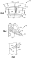
- FIGs 2-3 schematically illustrate an exemplary cooling scheme for providing cooling to the leading edge of a vane 130 in a vane cluster 100, where the vane 130 has a suction side surface facing the inbound region 102, according to one embodiment.
- the cooling scheme can be applied to vane clusters including three, four, or any other number of additional vanes, with the illustrated features being disposed on any vanes with a suction side surface facing the inbound region.
- the vane cluster 100 includes an outer diameter platform 110, an inner diameter platform 120, and multiple vanes 130 spanning from the outer diameter platform 110 to the inner diameter platform 120.
- Each of the vanes 130 includes a leading edge 104 and a trailing edge 106.
- the leading edge 104 is connected to the trailing edge 106 via a suction side surface and a pressure side surface.
- An inbound region 102 is defined between the vanes 130.
- Within the inbound region 102 is a visually obstructed region 105 on the suction side surface.
- the visually obstructed region 105 is a portion of the vane 130 where direct line of sight is obscured by another feature of the vane cluster 100, such as the other vane 130.
- each of the vanes 130 includes multiple core cooling passages 132, 134 (see Figure 3 ) including a leading edge core 132 and a trailing edge core 134.
- the leading edge core 132 is positioned proximate to the leading edge 104 of the vane 130, and provides a cooling flow that cools the leading edge 104.
- the trailing edge core 134 is provided proximate to the trailing edge 106 and provides a cooling flow that cools the trailing edge 106 of the vane 130.
- additional cores can be included beyond the leading edge core 132 and the trailing edge core 134.
- cooling holes 140 are included at or near the leading edge 104.
- Existing systems utilize cooling holes connecting the trailing edge core 134 to a forward portion of the suction side surface, and position the cooling holes correspondingly offset from the leading edge 104.
- the positioning of the holes required to allow coolant to be drawn from a trailing edge core 134 is too far downstream of the leading edge 104 of the vane, and insufficient cooling is provided to the leading edge 104 of the vane 130.
- each vane 130 that has a suction side surface facing an inbound region 102 can similarly require the cooling holes 140 and faces similar constructions difficulties using the existing techniques.
- the cooling hole configuration described herein can be extended to each of these vanes as well.
- the example vane cluster 100 shifts the forward most cooling holes 140 closer to the leading edge 104 of the vane 130, into the visually obstructed region 105 and connects the forward most cooling holes 140 to the leading edge core 132.
- FIG. 2 schematically illustrates a cross sectional view along view line A-A, of the example of Figure 2 .
- the set of EDM cooling holes 140 at the leading edge 104 includes eight EDM cooling holes 140.
- the visually obstructed region 105 includes from six to ten EDM cooling holes 140.
- the exemplary system of Figures 2 and 3 includes a greater flow of coolant through the leading edge core 132 than previous systems, and the removal of coolant from the leading edge core 132 due to the added EDM cooling holes 140 is offset by the increased cooling flow.
- the metering feature feeding the leading edge core was enlarged relative to previous systems.
- the trailing edge core 134 is connected to fewer film cooling holes than existing systems, as shaped EDM cooling holes 140 provide better film cooling with fewer EDM cooling holes 140 than laser machined holes.
- the improved film effectiveness of the shaped EDM cooling holes arises primarily due to the shape of the diffuser 144 shown in figure 4 .
- the EDM process enables the production of diffuser shapes that are more efficient than can be produced by the laser machine process.
- FIG. 4 schematically illustrates a cross section of an exemplary shaped hole 140.
- Figure 4 illustrates an alternative construction of the shaped film cooling hole 140 according to one example.
- the shaped EDM cooling holes 140 include a primary passage portion 142, and a diffuser portion 144 connecting the primary passage portion 142 to the visually obstructed region 105.
- the primary passage portion 142 directs the cooling flow from the source (the leading edge core 132) to the visually obstructed region 105, while the diffuser section 144 diffuses the flow through the film cooling hole 140.
- the diffusion increases the adhesion of the cooling flow to the exterior surface of the vane 130, increasing the film cooling effect.
- the primary passage portion 142 extends a majority of the wall's thickness and is joined to the diffuser portion 144 via an opening 146.
- the diffuser portion 144 expands the air, causing the air to remain closer to the surface.
- the diffuser portion 144 has a diameter 145 that increases from the opening 146 to an exit 147 at the visually obstructed region 105.
- the diameter of the primary passage portion 142 is approximately 0.015 inches (0.381 mm).
- the transition along the diffuser portion 144 can be gradual.
- the diffuser portion 144 can be configured such that each diffuser surface is angled 10 degrees from a cooling hole centerline defined by the primary passage 142. Such a configuration is referred to as a 10/10/10 hole.
- the diffuser portion 144 increases in diameter as a single step, or as multiple steps, instead of the gradual transition.
- the vane cluster 100 could include any number of additional vanes 130.
- the features related to, and facilitating, the leading edge EDM cooling holes 140, described above, are incorporated into each vane 130 whose suction side faces an inbound region 102.
Landscapes
- Engineering & Computer Science (AREA)
- Mechanical Engineering (AREA)
- General Engineering & Computer Science (AREA)
- Physics & Mathematics (AREA)
- Fluid Mechanics (AREA)
- Turbine Rotor Nozzle Sealing (AREA)
Claims (11)
- Leitschaufelsegment (100) für ein Gasturbinentriebwerk (20), umfassend:eine Außendurchmesserplattform (110);eine Innendurchmesserplattform (120);eine Vielzahl von Leitschaufeln (130), die sich von der Außendurchmesserplattform (110) bis zu der Innendurchmesserplattform (120) erstreckt;mindestens einen Eingangsbereich (102), der zwischen einer ersten Leitschaufel (130) der Vielzahl von Leitschaufeln (130) und einer zweiten Leitschaufel (130) der Vielzahl von Leitschaufeln (130) definiert ist, wobei die erste Leitschaufel (130) eine dem Eingangsbereich (102) zugewandte Saugseite und eine Anströmkante (104) beinhaltet und jede der Leitschaufeln (130) einen Anströmkanten-Kerndurchgang (132) und einen Abströmkanten-Kerndurchgang (134) beinhaltet; undeine Vielzahl von durch elektrische Entladung bearbeiteten (electrical discharge machined - EDM) Löchern (140), wobei jedes den Anströmkanten-Kerndurchgang (132) der ersten Leitschaufel (130) mit einer Außenfläche der ersten Leitschaufel (130) verbindet,dadurch gekennzeichnet, dass:
die EDM-Löcher (140) innerhalb von 12,7 mm (0,500 Zoll) von der Anströmkante (104) der ersten Leitschaufel (130) angeordnet sind und die Vielzahl von EDM-Löchern (140) aus sechs bis zehn Löchern besteht, wobei jedes EDM-Loch (140) in der Vielzahl von EDM-Löchern (140) einen primären Durchgangsabschnitt (142) und einen Diffusorabschnitt (144) beinhaltet. - Gasturbinentriebwerk (20), umfassend:einen Verdichterbereich (24);einen Brennkammerbereich (26), der mit dem Verdichterbereich (24) fluidverbunden ist;einen Turbinenbereich (28), der mit dem Brennkammerbereich (26) fluidverbunden ist, wobei der Turbinenbereich (28) eine Vielzahl von Stufen beinhaltet, wobei mindestens eine der Stufen einen Leitschaufelkranz beinhaltet, der mehrere in Umfangsrichtung benachbarte Leitschaufelsegmente (100) gemäß Anspruch 1 umfasst.
- Leitschaufelsegment (100) oder Gasturbinentriebwerk (20) nach Anspruch 1 oder 2, wobei jedes EDM-Loch (140) in der Vielzahl von EDM-Löchern (140) an der Anströmkante (104) der ersten Leitschaufel (130) angeordnet ist.
- Leitschaufelsegment (100) oder Gasturbinentriebwerk (20) nach einem der vorhergehenden Ansprüche, wobei jeder der primären Durchgangsabschnitte (142) einen Durchmesser von ungefähr 0,381 mm (0,015 Zoll) aufweist.
- Leitschaufelsegment (100) oder Gasturbinentriebwerk (20) nach einem der vorhergehenden Ansprüche, wobei jeder der primären Durchgangsabschnitte (142) eine Verbindung mit dem Anströmkanten-Kerndurchgang (132) der ersten Leitschaufel (130) herstellt und jeder der Diffusorabschnitte (144) eine Verbindung mit der Anströmkante (104) der ersten Leitschaufel (130) herstellt.
- Leitschaufelsegment (100) oder Gasturbinentriebwerk (20) nach einem der vorhergehenden Ansprüche, wobei jeder der Diffusorabschnitte (144) eine allmähliche Vergrößerung des Durchmessers von einer Verbindung mit dem entsprechenden primären Durchgangsabschnitt (142) zu einem Ausgang (147) an der Anströmkante (104) der ersten Leitschaufel (130) beinhaltet.
- Leitschaufelsegment (100) oder Gasturbinentriebwerk (20) nach einem der vorhergehenden Ansprüche, wobei jeder der Diffusorabschnitte (144) über eine Öffnung (146) mit dem entsprechenden primären Durchgangsabschnitt (142) verbunden ist und die Diffusorabschnitte (144) an der entsprechenden Öffnung (146) von den primären Durchgangsabschnitten (142) versetzt sind.
- Leitschaufelsegment (100) oder Gasturbinentriebwerk (20) nach einem der vorhergehenden Ansprüche, wobei jedes der EDM-Löcher (140) in der Vielzahl von EDM-Löchern (140) ein 10/10/10-Loch ist, wobei ein 10/10/10-Loch ein Loch ist, bei dem jede Diffusoroberfläche um 10 Grad von einer durch den primären Durchgangsabschnitt (142) definierten Kühllochmittellinie abgewinkelt ist.
- Leitschaufelsegment (100) oder Gasturbinentriebwerk (20) nach einem der vorhergehenden Ansprüche, wobei die Vielzahl von EDM-Löchern (140) aus acht Löchern besteht.
- Leitschaufelsegment (100) oder Gasturbinentriebwerk (20) nach einem der vorhergehenden Ansprüche, wobei die Vielzahl von Leitschaufeln (130) aus der ersten Leitschaufel (130) und der zweiten Leitschaufel (130) besteht.
- Leitschaufelsegment (100) oder Gasturbinentriebwerk (20) nach Anspruch 1, wobei jedes EDM-Loch (140) in der Vielzahl von EDM-Löchern (140) in einer optisch verdeckten Region (105) der ersten Leitschaufel (130) angeordnet ist, wobei die optisch verdeckte Region (105) ein Abschnitt der ersten Leitschaufel (130) ist, an dem die direkte Sichtlinie durch ein anderes Merkmal des Leitschaufelsegments (100) verdeckt ist.
Applications Claiming Priority (2)
| Application Number | Priority Date | Filing Date | Title |
|---|---|---|---|
| US201762553666P | 2017-09-01 | 2017-09-01 | |
| US15/790,505 US10641102B2 (en) | 2017-09-01 | 2017-10-23 | Turbine vane cluster including enhanced vane cooling |
Publications (2)
| Publication Number | Publication Date |
|---|---|
| EP3450697A1 EP3450697A1 (de) | 2019-03-06 |
| EP3450697B1 true EP3450697B1 (de) | 2024-12-25 |
Family
ID=63490255
Family Applications (1)
| Application Number | Title | Priority Date | Filing Date |
|---|---|---|---|
| EP18192117.2A Active EP3450697B1 (de) | 2017-09-01 | 2018-08-31 | Leitschaufelsegment und zugehöriges gasturbinentriebwerk |
Country Status (2)
| Country | Link |
|---|---|
| US (1) | US10641102B2 (de) |
| EP (1) | EP3450697B1 (de) |
Families Citing this family (1)
| Publication number | Priority date | Publication date | Assignee | Title |
|---|---|---|---|---|
| US11021966B2 (en) | 2019-04-24 | 2021-06-01 | Raytheon Technologies Corporation | Vane core assemblies and methods |
Citations (1)
| Publication number | Priority date | Publication date | Assignee | Title |
|---|---|---|---|---|
| US20120014809A1 (en) * | 2010-07-19 | 2012-01-19 | Franco Di Paola | High pressure turbine vane cooling hole distrubution |
Family Cites Families (11)
| Publication number | Priority date | Publication date | Assignee | Title |
|---|---|---|---|---|
| US7204019B2 (en) * | 2001-08-23 | 2007-04-17 | United Technologies Corporation | Method for repairing an apertured gas turbine component |
| US7008178B2 (en) | 2003-12-17 | 2006-03-07 | General Electric Company | Inboard cooled nozzle doublet |
| US20050135923A1 (en) | 2003-12-22 | 2005-06-23 | Todd Coons | Cooled vane cluster |
| EP1898051B8 (de) * | 2006-08-25 | 2017-08-02 | Ansaldo Energia IP UK Limited | Gasturbinenschaufel mit Kühlung der Leitkante |
| US20090169394A1 (en) * | 2007-12-28 | 2009-07-02 | General Electric Company | Method of forming cooling holes and turbine airfoil with hybrid-formed cooling holes |
| US9482100B2 (en) | 2012-02-15 | 2016-11-01 | United Technologies Corporation | Multi-lobed cooling hole |
| US20160003152A1 (en) | 2013-03-14 | 2016-01-07 | United Technologies Corporation | Gas turbine engine multi-vaned stator cooling configuration |
| US10041356B2 (en) * | 2014-08-15 | 2018-08-07 | United Technologies Corporation | Showerhead hole scheme apparatus and system |
| US10107140B2 (en) | 2014-12-08 | 2018-10-23 | United Technologies Corporation | Turbine airfoil segment having film cooling hole arrangement |
| US10030525B2 (en) * | 2015-03-18 | 2018-07-24 | General Electric Company | Turbine engine component with diffuser holes |
| US10273820B2 (en) | 2016-10-17 | 2019-04-30 | United Technologies Corporation | Turbine vane cooling arrangement |
-
2017
- 2017-10-23 US US15/790,505 patent/US10641102B2/en active Active
-
2018
- 2018-08-31 EP EP18192117.2A patent/EP3450697B1/de active Active
Patent Citations (1)
| Publication number | Priority date | Publication date | Assignee | Title |
|---|---|---|---|---|
| US20120014809A1 (en) * | 2010-07-19 | 2012-01-19 | Franco Di Paola | High pressure turbine vane cooling hole distrubution |
Also Published As
| Publication number | Publication date |
|---|---|
| EP3450697A1 (de) | 2019-03-06 |
| US20190071979A1 (en) | 2019-03-07 |
| US10641102B2 (en) | 2020-05-05 |
Similar Documents
| Publication | Publication Date | Title |
|---|---|---|
| US10808546B2 (en) | Gas turbine engine airfoil trailing edge suction side cooling | |
| US20160201474A1 (en) | Gas turbine engine component with film cooling hole feature | |
| US11143039B2 (en) | Turbine engine component including an axially aligned skin core passage interrupted by a pedestal | |
| US10041358B2 (en) | Gas turbine engine blade squealer pockets | |
| EP3179033B1 (de) | Kühlanordnung für laufschaufel einer gasturbine | |
| US10415428B2 (en) | Dual cavity baffle | |
| EP3004568B1 (de) | Gasturbinentriebwerk mit schwalbenschwanz-tobi-statorschaufel | |
| EP3091184B1 (de) | Kühlung der vorderkante einer turbinenschaufel | |
| US10533425B2 (en) | Doublet vane assembly for a gas turbine engine | |
| US10982552B2 (en) | Gas turbine engine component with film cooling hole | |
| US9957814B2 (en) | Gas turbine engine component with film cooling hole with accumulator | |
| EP3112596A1 (de) | Gasturbinenmotorschaufel mit biaxialem wandkühlkanal und zugehöriger gasturbinenmotor | |
| US10280756B2 (en) | Gas turbine engine airfoil | |
| US20160003152A1 (en) | Gas turbine engine multi-vaned stator cooling configuration | |
| US11828193B2 (en) | Vane core assemblies and methods | |
| EP3450686B1 (de) | Turbinenschaufel-cluster mit verbesserter plattformkühlung | |
| US11149548B2 (en) | Method of reducing manufacturing variation related to blocked cooling holes | |
| EP3450697B1 (de) | Leitschaufelsegment und zugehöriges gasturbinentriebwerk | |
| US20180038236A1 (en) | Gas turbine engine stator vane baffle arrangement | |
| EP3477055B1 (de) | Bauteil für ein gasturbinentriebwerk mit einem schaufelprofil | |
| EP2977557B1 (de) | Gekühlte schaufelstruktur und zugehöriges kühlverfahren | |
| US20150315929A1 (en) | Gas turbine engine airfoil cooling passage configuration |
Legal Events
| Date | Code | Title | Description |
|---|---|---|---|
| PUAI | Public reference made under article 153(3) epc to a published international application that has entered the european phase |
Free format text: ORIGINAL CODE: 0009012 |
|
| STAA | Information on the status of an ep patent application or granted ep patent |
Free format text: STATUS: THE APPLICATION HAS BEEN PUBLISHED |
|
| AK | Designated contracting states |
Kind code of ref document: A1 Designated state(s): AL AT BE BG CH CY CZ DE DK EE ES FI FR GB GR HR HU IE IS IT LI LT LU LV MC MK MT NL NO PL PT RO RS SE SI SK SM TR |
|
| AX | Request for extension of the european patent |
Extension state: BA ME |
|
| STAA | Information on the status of an ep patent application or granted ep patent |
Free format text: STATUS: REQUEST FOR EXAMINATION WAS MADE |
|
| 17P | Request for examination filed |
Effective date: 20190906 |
|
| RBV | Designated contracting states (corrected) |
Designated state(s): AL AT BE BG CH CY CZ DE DK EE ES FI FR GB GR HR HU IE IS IT LI LT LU LV MC MK MT NL NO PL PT RO RS SE SI SK SM TR |
|
| STAA | Information on the status of an ep patent application or granted ep patent |
Free format text: STATUS: EXAMINATION IS IN PROGRESS |
|
| 17Q | First examination report despatched |
Effective date: 20200428 |
|
| RAP1 | Party data changed (applicant data changed or rights of an application transferred) |
Owner name: RAYTHEON TECHNOLOGIES CORPORATION |
|
| RAP3 | Party data changed (applicant data changed or rights of an application transferred) |
Owner name: RTX CORPORATION |
|
| GRAP | Despatch of communication of intention to grant a patent |
Free format text: ORIGINAL CODE: EPIDOSNIGR1 |
|
| STAA | Information on the status of an ep patent application or granted ep patent |
Free format text: STATUS: GRANT OF PATENT IS INTENDED |
|
| INTG | Intention to grant announced |
Effective date: 20240718 |
|
| GRAS | Grant fee paid |
Free format text: ORIGINAL CODE: EPIDOSNIGR3 |
|
| GRAA | (expected) grant |
Free format text: ORIGINAL CODE: 0009210 |
|
| STAA | Information on the status of an ep patent application or granted ep patent |
Free format text: STATUS: THE PATENT HAS BEEN GRANTED |
|
| AK | Designated contracting states |
Kind code of ref document: B1 Designated state(s): AL AT BE BG CH CY CZ DE DK EE ES FI FR GB GR HR HU IE IS IT LI LT LU LV MC MK MT NL NO PL PT RO RS SE SI SK SM TR |
|
| REG | Reference to a national code |
Ref country code: GB Ref legal event code: FG4D |
|
| REG | Reference to a national code |
Ref country code: CH Ref legal event code: EP |
|
| REG | Reference to a national code |
Ref country code: DE Ref legal event code: R096 Ref document number: 602018077882 Country of ref document: DE |
|
| REG | Reference to a national code |
Ref country code: IE Ref legal event code: FG4D |
|
| REG | Reference to a national code |
Ref country code: LT Ref legal event code: MG9D |
|
| PG25 | Lapsed in a contracting state [announced via postgrant information from national office to epo] |
Ref country code: HR Free format text: LAPSE BECAUSE OF FAILURE TO SUBMIT A TRANSLATION OF THE DESCRIPTION OR TO PAY THE FEE WITHIN THE PRESCRIBED TIME-LIMIT Effective date: 20241225 |
|
| PG25 | Lapsed in a contracting state [announced via postgrant information from national office to epo] |
Ref country code: FI Free format text: LAPSE BECAUSE OF FAILURE TO SUBMIT A TRANSLATION OF THE DESCRIPTION OR TO PAY THE FEE WITHIN THE PRESCRIBED TIME-LIMIT Effective date: 20241225 |
|
| PG25 | Lapsed in a contracting state [announced via postgrant information from national office to epo] |
Ref country code: BG Free format text: LAPSE BECAUSE OF FAILURE TO SUBMIT A TRANSLATION OF THE DESCRIPTION OR TO PAY THE FEE WITHIN THE PRESCRIBED TIME-LIMIT Effective date: 20241225 |
|
| PG25 | Lapsed in a contracting state [announced via postgrant information from national office to epo] |
Ref country code: NO Free format text: LAPSE BECAUSE OF FAILURE TO SUBMIT A TRANSLATION OF THE DESCRIPTION OR TO PAY THE FEE WITHIN THE PRESCRIBED TIME-LIMIT Effective date: 20250325 |
|
| PG25 | Lapsed in a contracting state [announced via postgrant information from national office to epo] |
Ref country code: GR Free format text: LAPSE BECAUSE OF FAILURE TO SUBMIT A TRANSLATION OF THE DESCRIPTION OR TO PAY THE FEE WITHIN THE PRESCRIBED TIME-LIMIT Effective date: 20250326 Ref country code: LV Free format text: LAPSE BECAUSE OF FAILURE TO SUBMIT A TRANSLATION OF THE DESCRIPTION OR TO PAY THE FEE WITHIN THE PRESCRIBED TIME-LIMIT Effective date: 20241225 |
|
| PG25 | Lapsed in a contracting state [announced via postgrant information from national office to epo] |
Ref country code: RS Free format text: LAPSE BECAUSE OF FAILURE TO SUBMIT A TRANSLATION OF THE DESCRIPTION OR TO PAY THE FEE WITHIN THE PRESCRIBED TIME-LIMIT Effective date: 20250325 |
|
| REG | Reference to a national code |
Ref country code: NL Ref legal event code: MP Effective date: 20241225 |
|
| PG25 | Lapsed in a contracting state [announced via postgrant information from national office to epo] |
Ref country code: NL Free format text: LAPSE BECAUSE OF FAILURE TO SUBMIT A TRANSLATION OF THE DESCRIPTION OR TO PAY THE FEE WITHIN THE PRESCRIBED TIME-LIMIT Effective date: 20241225 |
|
| REG | Reference to a national code |
Ref country code: AT Ref legal event code: MK05 Ref document number: 1754318 Country of ref document: AT Kind code of ref document: T Effective date: 20241225 |
|
| PG25 | Lapsed in a contracting state [announced via postgrant information from national office to epo] |
Ref country code: SM Free format text: LAPSE BECAUSE OF FAILURE TO SUBMIT A TRANSLATION OF THE DESCRIPTION OR TO PAY THE FEE WITHIN THE PRESCRIBED TIME-LIMIT Effective date: 20241225 |
|
| PG25 | Lapsed in a contracting state [announced via postgrant information from national office to epo] |
Ref country code: PL Free format text: LAPSE BECAUSE OF FAILURE TO SUBMIT A TRANSLATION OF THE DESCRIPTION OR TO PAY THE FEE WITHIN THE PRESCRIBED TIME-LIMIT Effective date: 20241225 |
|
| PG25 | Lapsed in a contracting state [announced via postgrant information from national office to epo] |
Ref country code: ES Free format text: LAPSE BECAUSE OF FAILURE TO SUBMIT A TRANSLATION OF THE DESCRIPTION OR TO PAY THE FEE WITHIN THE PRESCRIBED TIME-LIMIT Effective date: 20241225 |
|
| PG25 | Lapsed in a contracting state [announced via postgrant information from national office to epo] |
Ref country code: IS Free format text: LAPSE BECAUSE OF FAILURE TO SUBMIT A TRANSLATION OF THE DESCRIPTION OR TO PAY THE FEE WITHIN THE PRESCRIBED TIME-LIMIT Effective date: 20250425 |
|
| PG25 | Lapsed in a contracting state [announced via postgrant information from national office to epo] |
Ref country code: PT Free format text: LAPSE BECAUSE OF FAILURE TO SUBMIT A TRANSLATION OF THE DESCRIPTION OR TO PAY THE FEE WITHIN THE PRESCRIBED TIME-LIMIT Effective date: 20250428 |
|
| PG25 | Lapsed in a contracting state [announced via postgrant information from national office to epo] |
Ref country code: EE Free format text: LAPSE BECAUSE OF FAILURE TO SUBMIT A TRANSLATION OF THE DESCRIPTION OR TO PAY THE FEE WITHIN THE PRESCRIBED TIME-LIMIT Effective date: 20241225 |
|
| PG25 | Lapsed in a contracting state [announced via postgrant information from national office to epo] |
Ref country code: AT Free format text: LAPSE BECAUSE OF FAILURE TO SUBMIT A TRANSLATION OF THE DESCRIPTION OR TO PAY THE FEE WITHIN THE PRESCRIBED TIME-LIMIT Effective date: 20241225 Ref country code: RO Free format text: LAPSE BECAUSE OF FAILURE TO SUBMIT A TRANSLATION OF THE DESCRIPTION OR TO PAY THE FEE WITHIN THE PRESCRIBED TIME-LIMIT Effective date: 20241225 |
|
| PG25 | Lapsed in a contracting state [announced via postgrant information from national office to epo] |
Ref country code: SK Free format text: LAPSE BECAUSE OF FAILURE TO SUBMIT A TRANSLATION OF THE DESCRIPTION OR TO PAY THE FEE WITHIN THE PRESCRIBED TIME-LIMIT Effective date: 20241225 |
|
| PG25 | Lapsed in a contracting state [announced via postgrant information from national office to epo] |
Ref country code: CZ Free format text: LAPSE BECAUSE OF FAILURE TO SUBMIT A TRANSLATION OF THE DESCRIPTION OR TO PAY THE FEE WITHIN THE PRESCRIBED TIME-LIMIT Effective date: 20241225 |
|
| PG25 | Lapsed in a contracting state [announced via postgrant information from national office to epo] |
Ref country code: IT Free format text: LAPSE BECAUSE OF FAILURE TO SUBMIT A TRANSLATION OF THE DESCRIPTION OR TO PAY THE FEE WITHIN THE PRESCRIBED TIME-LIMIT Effective date: 20241225 |
|
| PG25 | Lapsed in a contracting state [announced via postgrant information from national office to epo] |
Ref country code: SE Free format text: LAPSE BECAUSE OF FAILURE TO SUBMIT A TRANSLATION OF THE DESCRIPTION OR TO PAY THE FEE WITHIN THE PRESCRIBED TIME-LIMIT Effective date: 20241225 |
|
| REG | Reference to a national code |
Ref country code: DE Ref legal event code: R097 Ref document number: 602018077882 Country of ref document: DE |
|
| PG25 | Lapsed in a contracting state [announced via postgrant information from national office to epo] |
Ref country code: DK Free format text: LAPSE BECAUSE OF FAILURE TO SUBMIT A TRANSLATION OF THE DESCRIPTION OR TO PAY THE FEE WITHIN THE PRESCRIBED TIME-LIMIT Effective date: 20241225 |
|
| PGFP | Annual fee paid to national office [announced via postgrant information from national office to epo] |
Ref country code: DE Payment date: 20250724 Year of fee payment: 8 |
|
| PGFP | Annual fee paid to national office [announced via postgrant information from national office to epo] |
Ref country code: GB Payment date: 20250725 Year of fee payment: 8 |
|
| PGFP | Annual fee paid to national office [announced via postgrant information from national office to epo] |
Ref country code: FR Payment date: 20250725 Year of fee payment: 8 |
|
| PLBE | No opposition filed within time limit |
Free format text: ORIGINAL CODE: 0009261 |
|
| STAA | Information on the status of an ep patent application or granted ep patent |
Free format text: STATUS: NO OPPOSITION FILED WITHIN TIME LIMIT |
|
| REG | Reference to a national code |
Ref country code: CH Ref legal event code: L10 Free format text: ST27 STATUS EVENT CODE: U-0-0-L10-L00 (AS PROVIDED BY THE NATIONAL OFFICE) Effective date: 20251105 |
|
| 26N | No opposition filed |
Effective date: 20250926 |
|
| REG | Reference to a national code |
Ref country code: CH Ref legal event code: H13 Free format text: ST27 STATUS EVENT CODE: U-0-0-H10-H13 (AS PROVIDED BY THE NATIONAL OFFICE) Effective date: 20260324 |