EP3418480B1 - Falttürschliesssystem - Google Patents
Falttürschliesssystem Download PDFInfo
- Publication number
- EP3418480B1 EP3418480B1 EP18178257.4A EP18178257A EP3418480B1 EP 3418480 B1 EP3418480 B1 EP 3418480B1 EP 18178257 A EP18178257 A EP 18178257A EP 3418480 B1 EP3418480 B1 EP 3418480B1
- Authority
- EP
- European Patent Office
- Prior art keywords
- door panel
- plate
- hinge
- fixed
- door
- Prior art date
- Legal status (The legal status is an assumption and is not a legal conclusion. Google has not performed a legal analysis and makes no representation as to the accuracy of the status listed.)
- Active
Links
Images


Classifications
-
- E—FIXED CONSTRUCTIONS
- E05—LOCKS; KEYS; WINDOW OR DOOR FITTINGS; SAFES
- E05D—HINGES OR SUSPENSION DEVICES FOR DOORS, WINDOWS OR WINGS
- E05D15/00—Suspension arrangements for wings
- E05D15/26—Suspension arrangements for wings for folding wings
- E05D15/264—Suspension arrangements for wings for folding wings for bi-fold wings
- E05D15/266—Suspension arrangements for wings for folding wings for bi-fold wings comprising two pivots placed at opposite edges of the wing
-
- E—FIXED CONSTRUCTIONS
- E05—LOCKS; KEYS; WINDOW OR DOOR FITTINGS; SAFES
- E05D—HINGES OR SUSPENSION DEVICES FOR DOORS, WINDOWS OR WINGS
- E05D15/00—Suspension arrangements for wings
- E05D15/26—Suspension arrangements for wings for folding wings
-
- E—FIXED CONSTRUCTIONS
- E05—LOCKS; KEYS; WINDOW OR DOOR FITTINGS; SAFES
- E05D—HINGES OR SUSPENSION DEVICES FOR DOORS, WINDOWS OR WINGS
- E05D15/00—Suspension arrangements for wings
- E05D15/26—Suspension arrangements for wings for folding wings
- E05D15/264—Suspension arrangements for wings for folding wings for bi-fold wings
-
- E—FIXED CONSTRUCTIONS
- E05—LOCKS; KEYS; WINDOW OR DOOR FITTINGS; SAFES
- E05D—HINGES OR SUSPENSION DEVICES FOR DOORS, WINDOWS OR WINGS
- E05D5/00—Construction of single parts, e.g. the parts for attachment
- E05D5/02—Parts for attachment, e.g. flaps
- E05D5/04—Flat flaps
-
- E—FIXED CONSTRUCTIONS
- E05—LOCKS; KEYS; WINDOW OR DOOR FITTINGS; SAFES
- E05D—HINGES OR SUSPENSION DEVICES FOR DOORS, WINDOWS OR WINGS
- E05D5/00—Construction of single parts, e.g. the parts for attachment
- E05D5/02—Parts for attachment, e.g. flaps
- E05D5/04—Flat flaps
- E05D5/046—Flat flaps specially adapted for cabinets or furniture
-
- E—FIXED CONSTRUCTIONS
- E05—LOCKS; KEYS; WINDOW OR DOOR FITTINGS; SAFES
- E05D—HINGES OR SUSPENSION DEVICES FOR DOORS, WINDOWS OR WINGS
- E05D5/00—Construction of single parts, e.g. the parts for attachment
- E05D5/02—Parts for attachment, e.g. flaps
- E05D5/06—Bent flaps
-
- E—FIXED CONSTRUCTIONS
- E05—LOCKS; KEYS; WINDOW OR DOOR FITTINGS; SAFES
- E05D—HINGES OR SUSPENSION DEVICES FOR DOORS, WINDOWS OR WINGS
- E05D5/00—Construction of single parts, e.g. the parts for attachment
- E05D5/02—Parts for attachment, e.g. flaps
- E05D5/06—Bent flaps
- E05D5/065—Bent flaps specially adapted for cabinets or furniture
-
- E—FIXED CONSTRUCTIONS
- E05—LOCKS; KEYS; WINDOW OR DOOR FITTINGS; SAFES
- E05Y—INDEXING SCHEME ASSOCIATED WITH SUBCLASSES E05D AND E05F, RELATING TO CONSTRUCTION ELEMENTS, ELECTRIC CONTROL, POWER SUPPLY, POWER SIGNAL OR TRANSMISSION, USER INTERFACES, MOUNTING OR COUPLING, DETAILS, ACCESSORIES, AUXILIARY OPERATIONS NOT OTHERWISE PROVIDED FOR, APPLICATION THEREOF
- E05Y2201/00—Constructional elements; Accessories therefor
- E05Y2201/60—Suspension or transmission members; Accessories therefor
- E05Y2201/622—Suspension or transmission members elements
- E05Y2201/624—Arms
-
- E—FIXED CONSTRUCTIONS
- E05—LOCKS; KEYS; WINDOW OR DOOR FITTINGS; SAFES
- E05Y—INDEXING SCHEME ASSOCIATED WITH SUBCLASSES E05D AND E05F, RELATING TO CONSTRUCTION ELEMENTS, ELECTRIC CONTROL, POWER SUPPLY, POWER SIGNAL OR TRANSMISSION, USER INTERFACES, MOUNTING OR COUPLING, DETAILS, ACCESSORIES, AUXILIARY OPERATIONS NOT OTHERWISE PROVIDED FOR, APPLICATION THEREOF
- E05Y2900/00—Application of doors, windows, wings or fittings thereof
- E05Y2900/10—Application of doors, windows, wings or fittings thereof for buildings or parts thereof
- E05Y2900/13—Type of wing
- E05Y2900/132—Doors
-
- E—FIXED CONSTRUCTIONS
- E05—LOCKS; KEYS; WINDOW OR DOOR FITTINGS; SAFES
- E05Y—INDEXING SCHEME ASSOCIATED WITH SUBCLASSES E05D AND E05F, RELATING TO CONSTRUCTION ELEMENTS, ELECTRIC CONTROL, POWER SUPPLY, POWER SIGNAL OR TRANSMISSION, USER INTERFACES, MOUNTING OR COUPLING, DETAILS, ACCESSORIES, AUXILIARY OPERATIONS NOT OTHERWISE PROVIDED FOR, APPLICATION THEREOF
- E05Y2900/00—Application of doors, windows, wings or fittings thereof
- E05Y2900/10—Application of doors, windows, wings or fittings thereof for buildings or parts thereof
- E05Y2900/13—Type of wing
- E05Y2900/148—Windows
-
- E—FIXED CONSTRUCTIONS
- E05—LOCKS; KEYS; WINDOW OR DOOR FITTINGS; SAFES
- E05Y—INDEXING SCHEME ASSOCIATED WITH SUBCLASSES E05D AND E05F, RELATING TO CONSTRUCTION ELEMENTS, ELECTRIC CONTROL, POWER SUPPLY, POWER SIGNAL OR TRANSMISSION, USER INTERFACES, MOUNTING OR COUPLING, DETAILS, ACCESSORIES, AUXILIARY OPERATIONS NOT OTHERWISE PROVIDED FOR, APPLICATION THEREOF
- E05Y2900/00—Application of doors, windows, wings or fittings thereof
- E05Y2900/20—Application of doors, windows, wings or fittings thereof for furniture, e.g. cabinets
Definitions
- the following patent application for industrial invention relates to a closing system for door panels, in particular for folding doors, windows, cabinet door panels and the like.
- Folding doors are largely known on the market, which comprise one or more door panels that are hinged mutually in order to open or close an opening obtained in a wall. When the door panels are in open position, they are stacked along an orthogonal plane relative to the wall. When the door panels are in close position, they are disposed on a parallel plane relative to the wall in order to close the opening.
- the volume of the door panels stacked in open position partially reduces the width of the passage through the opening of the door. Otherwise said, the passage is not completely free.
- the door panels project both in the front and in the back, or only in the front relative to the wall, with a cumbersome volume caused by the width of the door panel.
- EP2839099 discloses a closure system that comprises two wings and one single mechanism composed of an articulated quadrilateral mechanism connected to the fixed structure, to the first wing and to the second wing.
- such a closure system is not versatile; in fact, it must provide for a different right-hand mechanism or a different left-hand mechanism according to the position of the opening on the right-hand side or on the left-hand side.
- Such a type of mechanism is designed for operating with a given measurement (the width of the door opening) and cannot be adapted to different measurements.
- Such an articulated quadrilateral mechanism needs to be provided with a connective rod that is hinged on two plates that are respectively fixed to the second door panel and to an upper crosspiece of the fixed structure.
- the hinging points of the connective rod are imposed by the dimensions of the articulated quadrilateral mechanism.
- DE202015003214 discloses a hinge mechanism used to open and close two door panels.
- the hinge mechanism comprises a first hinge that connects a first door panel to the fixed frame, a second hinge that connects a second door panel to the first door panel, and an articulated unit that connects the second door panel to the fixed frame.
- the articulated unit comprises a shelf that projects from one side of the second door panel in such a way to face the opening defined by the fixed frame when the door panels are in open position.
- the articulated unit comprises a lever that is hinged to the fixed frame and to the shelf.
- the first hinge, the second hinge and the articulated unit are disconnected.
- the door panels of the door disclosed in DE202015003214 are not completely closed one on top of the other.
- Such a drawback is caused by the provision of the shelf that projects from one side of the second door panel in such a way as to face the opening defined by the fixed frame when the door panels are in open position.
- the width of the second door panel is larger than the width of the first door panel to permit a connection between the shelf and the fixed frame. Therefore, when in open position, the second door panel partially closes the opening defined by the fixed frame.
- FR2448615 discloses an articulated mechanism for moving a folding door, comprising a first hinge that connects a first door panel to a fixed frame, a second hinge that connects a second door panel to the first door panel, and an articulated unit that connects the second door panel to the fixed frame.
- the first hinge, the second hinge and the articulated unit are not connected.
- the articulated unit comprises a shelf that projects from one side of the second door panel in such a way to face the opening defined by the fixed frame when the door panels are in open position, a first lever connected to the fixed frame and a second lever hinged to the first lever and to the shelf.
- the first lever and the second lever are disposed in such a way as to protrude from the opposite side relative to the door panels when the door panels are closed one on top of the other.
- FR2448615 is impaired by the fact that the door panels do not close completely one on top of the other because of the provision of the shelf. Moreover, because of the fact that the levers project from the opposite side compared to the door panels when the door panels are closed one on top of the other, the mechanism is cumbersome and aesthetically unpleasant.
- the purpose of the present invention is to eliminate the drawbacks of the prior art by disclosing a closing system for door panels that is characterized by a reduced volume when the door panels are closed, being at the same time reliable, versatile, easy to make and install.
- the closing system for door panels according to the invention is defined by claim 1.
- first hinge unit, the second hinge unit and the articulated unit are not connected.
- Such a mechanism can operate also for different widths of the opening defined by the fixed frame.
- the parts of the mechanism do not have a predefined direction and can be indifferently used for door panels that open towards the right-hand side or the left-hand side.
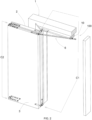
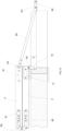
- the closing system (100) comprises:
- the fixed frame (1) is intended to be fixed to a wall wherein a rectangular opening is obtained.
- the fixed frame (1) generally comprises a crosspiece (10) and an upright (11) and defines the perimeter of the opening of the wall.
- the door panels (2, 3) are rectangular and identical, with an area that is equal to half of the area of the opening defined by the fixed frame (1).
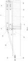
- a mechanism connects the first door panel (2) to the fixed frame and the second door panel (3) to the first door panel, in such a way that the door panels (2, 3) can go from an open position ( Fig. 2 ), wherein the door panels leave the opening defined by the fixed frame (1) open, to a close position ( Fig. 7 ), wherein the door panels close the opening defined by the fixed frame (1).
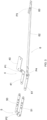
- the mechanism comprises:
- the first hinge unit (C1), the second hinge unit (C2) and the articulated unit (6) are not connected.
- the first hinge unit (C1) comprises an upper hinge (4) disposed above an upper edge of the first door panel (2) and a lower hinge (7) disposed under a lower edge of the first door panel.
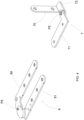
- the upper hinge (4) of the first hinge unit comprises a first plate (40) and a second plate (41).
- Each plate (40, 41) has an "L" shape and comprises a long arm and a short arm.
- the short arms of the two plates (40, 41) are mutually hinged by means of a pin (P1).
- the first plate (40) is fixed under the crosspiece (10) of the fixed frame near the upright (11).
- the second plate (41) is fixed on an upper edge of the first door panel (2) near a lateral end of the first door panel (2) in such a way that the pin (P1) is disposed near the lateral end of the first door panel.
- the upper hinge (4) permits the rotation of the first door panel (2) relative to the fixed frame (1) around the pin (P1).
- the lower hinge (7) of the first hinge unit comprises a first plate (70) and a second plate (71).
- the first plate (70) has an "L"-shaped section with a wing (72) disposed on an orthogonal plane relative to the first plate (70).
- the second plate (71) has an "L"-shape in plan view and comprises a long arm and a short arm. The short arm of the second plate (71) is hinged to the wing (72) of the first plate by means of a pin (P5).
- the first plate (70) is fixed to the upright (11) of the fixed frame near a lower end of the upright.
- the second plate (71) is fixed under a lower edge of the first door panel (2) near a lateral end of the first door panel (2), in such a way that the pin (P5) of the lower hinge is disposed near the lateral end of the first door panel and is vertically aligned with the axis of the pin (P1) of the upper hinge of the first hinge unit.
- the first door panel (2) can rotate in a balanced manner relative to the fixed frame (1) around the axis of the pins (P1 and P5) of the lower hinge and of the upper hinge.
- the second hinge unit (C2) comprises an upper hinge (5) disposed above an upper edge of the first door panel (2) and of the second door panel (3), and a lower hinge (8) disposed under a lower edge of the first door panel and the second door panel.
- the upper hinge (5) of the second hinge unit comprises a first plate (50) and a second plate (51).
- Each plate (50, 51) has an "L" shape in plan view and comprises a long arm and a short arm.
- the short arms of the two plates (50, 51) are rounded and mutually hinged by means of a pin (P2).
- the first plate (50) of the upper hinge of the second hinge unit is fixed on the upper edge of the first door panel (2) near a lateral end of the first door panel (2) in distal position relative to the upper hinge (4) of the first hinge unit.
- the upper hinge (5) of the second hinge unit permits a rotation of the second door panel (3) relative to the first door panel (2) around the pin (P2).
- the lower hinge (8) of the second hinge unit is substantially identical to the upper hinge (5) of the second hinge unit.
- the lower hinge (8) of the second hinge unit comprises a first plate (80) and a second plate (81).
- Each plate (80, 81) has an "L" shape and comprises a long arm and a short arm.
- the short arms of the two plates (80, 81) are rounded and mutually hinged by means of a pin (P6).
- the first plate (80) of the lower hinge is fixed under the lower edge of the first door panel (2) near a lateral end of the first door panel (2) in distal position relative to the lower hinge (7) of the first hinge unit, in such a way that the axis of the pin (P6) of the lower hinge coincides with the axis of the pin (P2) of the upper hinge of the second hinge unit.
- the second door panel (3) can rotate in a balanced manner relative to the first door panel (2) around the axis of the pins (P2 and P6) of the upper hinge and of the lower hinge of the second hinge unit.
- the articulated unit (6) of the mechanism comprises:
- the articulated unit (6) of the upper mechanism is provided with two hinges, in the first pin (P3) and in the second pin (P4), in such a way as to follow the movement of the second door panel (3) from the open position of the door panels ( Fig. 2 ) to the close position of the door panels ( Fig. 7 ).
- the second plate (61) of the articulated unit is fixed on the upper edge of the second door panel (3) near a lateral end of the second door panel (3) in distal position relative to the upper hinge (5) of the second hinge unit, in such a way that the second door panel is stopped against the first door panel when the door panels are in open position.
- the door panels (2, 3) when the door panels (2, 3) are in open position, the door panels (2, 3) are stacked one behind the other, and the two plates of the upper and lower hinges of the second hinge unit are in parallel position. In such a situation, the two door panels (2, 3) have a reduced volume and are substantially flush with the wall whereon the fixed frame (1) is mounted, without hindering the opening defined by the fixed frame (1).
- the length of the connective rod (62) is chosen in such a way that the first plate (60) is fixed to the crosspiece (10) in an intermediate position of the crosspiece.
- the design and the mounting of the mechanism is easy and fast because no complicated calculations are needed to design the first plate (60), with reference to the hinging point of said first plate (60) relative to the crosspiece (10).
Landscapes
- Engineering & Computer Science (AREA)
- Mechanical Engineering (AREA)
- Hinges (AREA)
Claims (5)
- Schließsystem (100) für Türpaneele, umfassend:- einen festen Rahmen (1), der eine Öffnung definiert,- ein erstes Türpaneel (2), das mit dem festen Rahmen verbunden ist,- ein zweites Türpaneel (3), das mit dem ersten Türpaneel verbunden ist, und- einen Mechanismus, der das erste Türpaneel (2) mit dem festen Rahmen (1) und das zweite Türpaneel (3) mit dem ersten Türpaneel verbindet, so dass die Türpaneele (2, 3) von einer Offenstellung, in der die Türpaneele die vom festen Rahmen (1) definierte Öffnung offenlassen, in eine Geschlossenstellung übergehen können, in der die Türpaneele die von dem festen Rahmen (1) definierte Öffnung schließen;wobei der Mechanismus umfasst:- eine erste Scharniereinheit (C1), die das erste Türpaneel (2) mit dem festen Rahmen verbindet,- eine zweite Scharniereinheit (C2), die das zweite Türpaneel (3) mit dem ersten Türpaneel verbindet, und- eine Gelenkeinheit (6), die das zweite Türpaneel (3) mit dem festen Rahmen (1) verbindet;wobei die Gelenkeinheit (6) umfasst:- eine erste Platte (60), die dazu bestimmt ist, an dem festen Rahmen (1) befestigt zu werden,- eine zweite Platte (61), die dazu bestimmt ist, an dem zweiten Türpaneel (3) befestigt zu werden, und- eine Verbindungsstange (62), die an der ersten Platte (60) mittels eines ersten Stiftes (P3) und an der zweiten Platte (63) mittels eines zweiten Stiftes (P4) angelenkt ist;wobei die zweite Platte (61) der Gelenkeinheit an einer oberen Kante des zweiten Türpaneels (3) verbunden ist, so dass das zweite Türpaneel an der ersten Tür in Anschlag kommt, wenn die Türpaneele sich in Offenstellung befinden;die zweite Platte (61) der Gelenkeinheit ist an einer oberen Kante des zweiten Türpaneels (3) nahe einem seitlichen Ende des zweiten Türpaneels befestigt und die erste Platte (60) der Gelenkeinheit ist an einem Querträger (10) des festen Rahmens in einer Zwischenstellung des Querträgers befestigt;wobei die Scharniereinheit (C1) ein oberes Scharnier (4) umfasst, das über einer oberen Kante des ersten Türpaneels (2) angeordnet ist und ein unteres Scharnier (7), das unter einer unteren Kante der ersten Türpaneels angeordnet ist,dadurch gekennzeichnet, dassdie erste Scharniereinheit (C1), die zweite Scharniereinheit (C2) und die Gelenkeinheit (6) nicht miteinander verbunden sind;wobei das obere Scharnier (4) eine ersten Platte (40) umfasst, die dazu bestimmt ist, an dem Querträger (10) des festen Rahmens befestigt zu werden, und eine zweite Platte (41), die dazu bestimmt ist, an der oberen Kante des ersten Türpaneels befestigt zu werden, wobei die Platten (40, 41) des oberen Scharniers eine L-förmige Form mit einem langen und einem kurzen Arm aufweisen, wobei die kurzen Arme mittels eines Stifts (P1) miteinander verbunden sind.
- Schließsystem (100) nach Anspruch 1, wobei das untere Scharnier (7) eine ersten Platte (70) umfasst, die dazu bestimmt ist, an einem Pfosten (11) des festen Rahmens befestigt zu werden, und eine zweite Platte (71), die dazu bestimmt ist, an der unteren Kante des ersten Türpaneels befestigt zu werden; wobei die erste Platte (70) im Querschnitt L-förmig ist, mit einem zur ersten Platte rechtwinkligen Flügel (72), und die zweite Platte (71) des unteren Scharniers im Grundriss L-förmig ist, mit einem langen Arm und einem kurzen Arm, wobei der kurze Arm der zweiten Platte an dem Flügel (72) der ersten Platte mittels eines Stifts (P5) angelenkt ist.
- Schließsystem (100) nach einem der vorstehenden Ansprüche, wobei die zweite Scharniereinheit (C2) ein oberes Scharnier (5) umfasst, das über einer oberen Kante des ersten und des zweiten Türpaneels (2, 3) angeordnet ist, und ein unteres Scharnier (8), das unter einer unteren Kante des ersten und des zweiten Türpaneels (2, 3) angeordnet ist.
- Schließsystem (100) nach Anspruch 3, wobei das obere Scharnier (5) der zweiten Scharniereinheit eine erste Platte (50) umfasst, die dazu bestimmt ist, an der oberen Kante des ersten Türpaneels befestigt zu werden, und eine zweite Platte (51), die dazu bestimmt ist, an der oberen Kante des zweiten Türpaneels befestigt zu werden, wobei die Platten (50, 51) des oberen Scharniers eine L-förmige Form mit einem langen und einem kurzen, abgerundeten Arm aufweisen, wobei die kurzen abgerundeten Arme mittels eines Stifts (P2) angelenkt sind.
- Schließsystem (100) nach Anspruch 3 oder 4, wobei das untere Scharnier (8) der zweiten Scharniereinheit eine ersten Platte (80) umfasst, die dazu bestimmt ist, an der unteren Kante des ersten Türpaneels befestigt zu werden, und eine zweite Platte (81), die dazu bestimmt ist, an der untere Kante des zweiten Türpaneels befestigt zu werden, wobei die Platten (80, 81) des unteren Scharniers eine L-förmige Form mit einem langen und einem kurzen, abgerundeten Arm aufweisen, wobei die kurzen, abgerundeten Arme mittels eines Stifts (P6) angelenkt sind.
Applications Claiming Priority (1)
| Application Number | Priority Date | Filing Date | Title |
|---|---|---|---|
| IT201700069765 | 2017-06-22 |
Publications (2)
| Publication Number | Publication Date |
|---|---|
| EP3418480A1 EP3418480A1 (de) | 2018-12-26 |
| EP3418480B1 true EP3418480B1 (de) | 2025-01-08 |
Family
ID=60294231
Family Applications (1)
| Application Number | Title | Priority Date | Filing Date |
|---|---|---|---|
| EP18178257.4A Active EP3418480B1 (de) | 2017-06-22 | 2018-06-18 | Falttürschliesssystem |
Country Status (2)
| Country | Link |
|---|---|
| EP (1) | EP3418480B1 (de) |
| ES (1) | ES3023042T3 (de) |
Families Citing this family (2)
| Publication number | Priority date | Publication date | Assignee | Title |
|---|---|---|---|---|
| AT522463B1 (de) | 2019-06-27 | 2020-11-15 | Blum Gmbh Julius | Möbelantrieb |
| JP7805182B2 (ja) * | 2022-01-28 | 2026-01-23 | 帝国繊維株式会社 | 防災用車両 |
Citations (1)
| Publication number | Priority date | Publication date | Assignee | Title |
|---|---|---|---|---|
| EP2839099B1 (de) * | 2012-04-17 | 2017-03-29 | Celegon S.r.l. | Henkelverschluss für türen, fenster oder dergleichen |
Family Cites Families (3)
| Publication number | Priority date | Publication date | Assignee | Title |
|---|---|---|---|---|
| FR2448615A1 (fr) * | 1979-02-09 | 1980-09-05 | Chazalviel Jean Francois | Ferrure pour portes pliantes |
| KR200473952Y1 (ko) * | 2012-10-29 | 2014-08-11 | 강윤구 | 접이식 도어용 힌지 브래킷 |
| DE202015003214U1 (de) * | 2015-05-04 | 2015-07-06 | Andreas Köhler | Dichtschließende, Drehflügel-Raumspartür mit Entriegelung zum Vergrößern der Öffnungsbreite |
-
2018
- 2018-06-18 ES ES18178257T patent/ES3023042T3/es active Active
- 2018-06-18 EP EP18178257.4A patent/EP3418480B1/de active Active
Patent Citations (1)
| Publication number | Priority date | Publication date | Assignee | Title |
|---|---|---|---|---|
| EP2839099B1 (de) * | 2012-04-17 | 2017-03-29 | Celegon S.r.l. | Henkelverschluss für türen, fenster oder dergleichen |
Also Published As
| Publication number | Publication date |
|---|---|
| ES3023042T3 (en) | 2025-05-29 |
| EP3418480A1 (de) | 2018-12-26 |
Similar Documents
| Publication | Publication Date | Title |
|---|---|---|
| CN110388150B (zh) | 用于移动家具物品的家具柜上接收的家具部件的装置 | |
| US9790718B2 (en) | Door hinge | |
| US6170195B1 (en) | Door assembly | |
| US4083082A (en) | Concealed self-closing hinge for panel door cabinet structure | |
| US5103532A (en) | Flat-mounted cabinet door hinge having low profile | |
| US7814621B1 (en) | Stay-closed hinge | |
| EP3418480B1 (de) | Falttürschliesssystem | |
| CN115126364A (zh) | 以180度旋转的隐蔽式外部铰链 | |
| US20190323275A1 (en) | Folding barn style door and hardware | |
| US4332053A (en) | Concealed hinge for doors, flaps, or the like | |
| EP1640537A2 (de) | Stossdämpfende und stabilisierende Stoppvorrichting für Schiebetüren und -läden | |
| US20210277693A1 (en) | Hinge having pinch protection and method for displacing securing parts of a hinge | |
| US2891274A (en) | Double acting spring hinge for folding doors | |
| AU2009271760B2 (en) | Door assembly | |
| CA2045302C (en) | Hinge | |
| US2812539A (en) | Hinge | |
| ES2963275T3 (es) | Puerta con función de prevención de pellizcos en los dedos | |
| KR101137823B1 (ko) | 여닫이문 | |
| HU222412B1 (hu) | Vasalatelrendezés | |
| KR20120122428A (ko) | 180도 개문이 가능한 가구용 엑스바형 도어 힌지 | |
| KR20190002676U (ko) | 스윙 도어 | |
| JP2589363Y2 (ja) | ヒンジ | |
| KR200190929Y1 (ko) | 가구용 도어힌지 | |
| KR20240015258A (ko) | 회전축 방식 여닫이도어의 힌지장치 | |
| KR20230070151A (ko) | 교체가능하도록 조립이 되는 측면프레임을 가지는 3연동 슬라이딩도어 |
Legal Events
| Date | Code | Title | Description |
|---|---|---|---|
| PUAI | Public reference made under article 153(3) epc to a published international application that has entered the european phase |
Free format text: ORIGINAL CODE: 0009012 |
|
| STAA | Information on the status of an ep patent application or granted ep patent |
Free format text: STATUS: THE APPLICATION HAS BEEN PUBLISHED |
|
| AK | Designated contracting states |
Kind code of ref document: A1 Designated state(s): AL AT BE BG CH CY CZ DE DK EE ES FI FR GB GR HR HU IE IS IT LI LT LU LV MC MK MT NL NO PL PT RO RS SE SI SK SM TR |
|
| AX | Request for extension of the european patent |
Extension state: BA ME |
|
| STAA | Information on the status of an ep patent application or granted ep patent |
Free format text: STATUS: REQUEST FOR EXAMINATION WAS MADE |
|
| 17P | Request for examination filed |
Effective date: 20190620 |
|
| RBV | Designated contracting states (corrected) |
Designated state(s): AL AT BE BG CH CY CZ DE DK EE ES FI FR GB GR HR HU IE IS IT LI LT LU LV MC MK MT NL NO PL PT RO RS SE SI SK SM TR |
|
| STAA | Information on the status of an ep patent application or granted ep patent |
Free format text: STATUS: EXAMINATION IS IN PROGRESS |
|
| 17Q | First examination report despatched |
Effective date: 20220420 |
|
| GRAP | Despatch of communication of intention to grant a patent |
Free format text: ORIGINAL CODE: EPIDOSNIGR1 |
|
| STAA | Information on the status of an ep patent application or granted ep patent |
Free format text: STATUS: GRANT OF PATENT IS INTENDED |
|
| RIC1 | Information provided on ipc code assigned before grant |
Ipc: E05D 5/06 20060101ALN20240910BHEP Ipc: E05D 5/04 20060101ALN20240910BHEP Ipc: E05D 15/26 20060101AFI20240910BHEP |
|
| INTG | Intention to grant announced |
Effective date: 20240930 |
|
| GRAS | Grant fee paid |
Free format text: ORIGINAL CODE: EPIDOSNIGR3 |
|
| GRAA | (expected) grant |
Free format text: ORIGINAL CODE: 0009210 |
|
| STAA | Information on the status of an ep patent application or granted ep patent |
Free format text: STATUS: THE PATENT HAS BEEN GRANTED |
|
| AK | Designated contracting states |
Kind code of ref document: B1 Designated state(s): AL AT BE BG CH CY CZ DE DK EE ES FI FR GB GR HR HU IE IS IT LI LT LU LV MC MK MT NL NO PL PT RO RS SE SI SK SM TR |
|
| REG | Reference to a national code |
Ref country code: GB Ref legal event code: FG4D |
|
| RIN1 | Information on inventor provided before grant (corrected) |
Inventor name: BIANCHINI, LUCA Inventor name: PAGLIAROLI, GERARDO |
|
| REG | Reference to a national code |
Ref country code: CH Ref legal event code: EP |
|
| REG | Reference to a national code |
Ref country code: DE Ref legal event code: R096 Ref document number: 602018078306 Country of ref document: DE |
|
| REG | Reference to a national code |
Ref country code: IE Ref legal event code: FG4D |
|
| REG | Reference to a national code |
Ref country code: LT Ref legal event code: MG9D |
|
| P01 | Opt-out of the competence of the unified patent court (upc) registered |
Free format text: CASE NUMBER: APP_16456/2025 Effective date: 20250404 |
|
| REG | Reference to a national code |
Ref country code: NL Ref legal event code: MP Effective date: 20250108 |
|
| REG | Reference to a national code |
Ref country code: ES Ref legal event code: FG2A Ref document number: 3023042 Country of ref document: ES Kind code of ref document: T3 Effective date: 20250529 |
|
| REG | Reference to a national code |
Ref country code: AT Ref legal event code: MK05 Ref document number: 1758422 Country of ref document: AT Kind code of ref document: T Effective date: 20250108 |
|
| PG25 | Lapsed in a contracting state [announced via postgrant information from national office to epo] |
Ref country code: NL Free format text: LAPSE BECAUSE OF FAILURE TO SUBMIT A TRANSLATION OF THE DESCRIPTION OR TO PAY THE FEE WITHIN THE PRESCRIBED TIME-LIMIT Effective date: 20250108 |
|
| PG25 | Lapsed in a contracting state [announced via postgrant information from national office to epo] |
Ref country code: RS Free format text: LAPSE BECAUSE OF FAILURE TO SUBMIT A TRANSLATION OF THE DESCRIPTION OR TO PAY THE FEE WITHIN THE PRESCRIBED TIME-LIMIT Effective date: 20250408 |
|
| PG25 | Lapsed in a contracting state [announced via postgrant information from national office to epo] |
Ref country code: FI Free format text: LAPSE BECAUSE OF FAILURE TO SUBMIT A TRANSLATION OF THE DESCRIPTION OR TO PAY THE FEE WITHIN THE PRESCRIBED TIME-LIMIT Effective date: 20250108 |
|
| PG25 | Lapsed in a contracting state [announced via postgrant information from national office to epo] |
Ref country code: PL Free format text: LAPSE BECAUSE OF FAILURE TO SUBMIT A TRANSLATION OF THE DESCRIPTION OR TO PAY THE FEE WITHIN THE PRESCRIBED TIME-LIMIT Effective date: 20250108 |
|
| PGFP | Annual fee paid to national office [announced via postgrant information from national office to epo] |
Ref country code: DE Payment date: 20250626 Year of fee payment: 8 |
|
| PG25 | Lapsed in a contracting state [announced via postgrant information from national office to epo] |
Ref country code: NO Free format text: LAPSE BECAUSE OF FAILURE TO SUBMIT A TRANSLATION OF THE DESCRIPTION OR TO PAY THE FEE WITHIN THE PRESCRIBED TIME-LIMIT Effective date: 20250408 Ref country code: IS Free format text: LAPSE BECAUSE OF FAILURE TO SUBMIT A TRANSLATION OF THE DESCRIPTION OR TO PAY THE FEE WITHIN THE PRESCRIBED TIME-LIMIT Effective date: 20250508 |
|
| PG25 | Lapsed in a contracting state [announced via postgrant information from national office to epo] |
Ref country code: HR Free format text: LAPSE BECAUSE OF FAILURE TO SUBMIT A TRANSLATION OF THE DESCRIPTION OR TO PAY THE FEE WITHIN THE PRESCRIBED TIME-LIMIT Effective date: 20250108 |
|
| PG25 | Lapsed in a contracting state [announced via postgrant information from national office to epo] |
Ref country code: PT Free format text: LAPSE BECAUSE OF FAILURE TO SUBMIT A TRANSLATION OF THE DESCRIPTION OR TO PAY THE FEE WITHIN THE PRESCRIBED TIME-LIMIT Effective date: 20250508 Ref country code: LV Free format text: LAPSE BECAUSE OF FAILURE TO SUBMIT A TRANSLATION OF THE DESCRIPTION OR TO PAY THE FEE WITHIN THE PRESCRIBED TIME-LIMIT Effective date: 20250108 |
|
| PGFP | Annual fee paid to national office [announced via postgrant information from national office to epo] |
Ref country code: FR Payment date: 20250624 Year of fee payment: 8 |
|
| PG25 | Lapsed in a contracting state [announced via postgrant information from national office to epo] |
Ref country code: GR Free format text: LAPSE BECAUSE OF FAILURE TO SUBMIT A TRANSLATION OF THE DESCRIPTION OR TO PAY THE FEE WITHIN THE PRESCRIBED TIME-LIMIT Effective date: 20250409 Ref country code: BG Free format text: LAPSE BECAUSE OF FAILURE TO SUBMIT A TRANSLATION OF THE DESCRIPTION OR TO PAY THE FEE WITHIN THE PRESCRIBED TIME-LIMIT Effective date: 20250108 |
|
| PG25 | Lapsed in a contracting state [announced via postgrant information from national office to epo] |
Ref country code: AT Free format text: LAPSE BECAUSE OF FAILURE TO SUBMIT A TRANSLATION OF THE DESCRIPTION OR TO PAY THE FEE WITHIN THE PRESCRIBED TIME-LIMIT Effective date: 20250108 |
|
| PG25 | Lapsed in a contracting state [announced via postgrant information from national office to epo] |
Ref country code: SE Free format text: LAPSE BECAUSE OF FAILURE TO SUBMIT A TRANSLATION OF THE DESCRIPTION OR TO PAY THE FEE WITHIN THE PRESCRIBED TIME-LIMIT Effective date: 20250108 |
|
| PG25 | Lapsed in a contracting state [announced via postgrant information from national office to epo] |
Ref country code: SM Free format text: LAPSE BECAUSE OF FAILURE TO SUBMIT A TRANSLATION OF THE DESCRIPTION OR TO PAY THE FEE WITHIN THE PRESCRIBED TIME-LIMIT Effective date: 20250108 |
|
| PGFP | Annual fee paid to national office [announced via postgrant information from national office to epo] |
Ref country code: ES Payment date: 20250710 Year of fee payment: 8 |
|
| REG | Reference to a national code |
Ref country code: DE Ref legal event code: R097 Ref document number: 602018078306 Country of ref document: DE |
|
| PG25 | Lapsed in a contracting state [announced via postgrant information from national office to epo] |
Ref country code: DK Free format text: LAPSE BECAUSE OF FAILURE TO SUBMIT A TRANSLATION OF THE DESCRIPTION OR TO PAY THE FEE WITHIN THE PRESCRIBED TIME-LIMIT Effective date: 20250108 |
|
| PGFP | Annual fee paid to national office [announced via postgrant information from national office to epo] |
Ref country code: CH Payment date: 20250701 Year of fee payment: 8 |
|
| PG25 | Lapsed in a contracting state [announced via postgrant information from national office to epo] |
Ref country code: CZ Free format text: LAPSE BECAUSE OF FAILURE TO SUBMIT A TRANSLATION OF THE DESCRIPTION OR TO PAY THE FEE WITHIN THE PRESCRIBED TIME-LIMIT Effective date: 20250108 Ref country code: EE Free format text: LAPSE BECAUSE OF FAILURE TO SUBMIT A TRANSLATION OF THE DESCRIPTION OR TO PAY THE FEE WITHIN THE PRESCRIBED TIME-LIMIT Effective date: 20250108 |
|
| PG25 | Lapsed in a contracting state [announced via postgrant information from national office to epo] |
Ref country code: RO Free format text: LAPSE BECAUSE OF FAILURE TO SUBMIT A TRANSLATION OF THE DESCRIPTION OR TO PAY THE FEE WITHIN THE PRESCRIBED TIME-LIMIT Effective date: 20250108 |
|
| PG25 | Lapsed in a contracting state [announced via postgrant information from national office to epo] |
Ref country code: SK Free format text: LAPSE BECAUSE OF FAILURE TO SUBMIT A TRANSLATION OF THE DESCRIPTION OR TO PAY THE FEE WITHIN THE PRESCRIBED TIME-LIMIT Effective date: 20250108 |
|
| PLBE | No opposition filed within time limit |
Free format text: ORIGINAL CODE: 0009261 |
|
| STAA | Information on the status of an ep patent application or granted ep patent |
Free format text: STATUS: NO OPPOSITION FILED WITHIN TIME LIMIT |
|
| 26N | No opposition filed |
Effective date: 20251009 |
|
| PG25 | Lapsed in a contracting state [announced via postgrant information from national office to epo] |
Ref country code: MC Free format text: LAPSE BECAUSE OF FAILURE TO SUBMIT A TRANSLATION OF THE DESCRIPTION OR TO PAY THE FEE WITHIN THE PRESCRIBED TIME-LIMIT Effective date: 20250108 |
|
| PG25 | Lapsed in a contracting state [announced via postgrant information from national office to epo] |
Ref country code: LU Free format text: LAPSE BECAUSE OF NON-PAYMENT OF DUE FEES Effective date: 20250618 |
|
| GBPC | Gb: european patent ceased through non-payment of renewal fee |
Effective date: 20250618 |
|
| REG | Reference to a national code |
Ref country code: BE Ref legal event code: MM Effective date: 20250630 |