EP3418436B1 - Schlauchvorrichtung und anordnung - Google Patents
Schlauchvorrichtung und anordnung Download PDFInfo
- Publication number
- EP3418436B1 EP3418436B1 EP17177250.2A EP17177250A EP3418436B1 EP 3418436 B1 EP3418436 B1 EP 3418436B1 EP 17177250 A EP17177250 A EP 17177250A EP 3418436 B1 EP3418436 B1 EP 3418436B1
- Authority
- EP
- European Patent Office
- Prior art keywords
- hose
- pressure
- water
- sectional area
- corrugated hose
- Prior art date
- Legal status (The legal status is an assumption and is not a legal conclusion. Google has not performed a legal analysis and makes no representation as to the accuracy of the status listed.)
- Active
Links
Images


Classifications
-
- A—HUMAN NECESSITIES
- A47—FURNITURE; DOMESTIC ARTICLES OR APPLIANCES; COFFEE MILLS; SPICE MILLS; SUCTION CLEANERS IN GENERAL
- A47L—DOMESTIC WASHING OR CLEANING; SUCTION CLEANERS IN GENERAL
- A47L15/00—Washing or rinsing machines for crockery or tableware
- A47L15/42—Details
- A47L15/4214—Water supply, recirculation or discharge arrangements; Devices therefor
- A47L15/4217—Fittings for water supply, e.g. valves or plumbing means to connect to cold or warm water lines, aquastops
-
- D—TEXTILES; PAPER
- D06—TREATMENT OF TEXTILES OR THE LIKE; LAUNDERING; FLEXIBLE MATERIALS NOT OTHERWISE PROVIDED FOR
- D06F—LAUNDERING, DRYING, IRONING, PRESSING OR FOLDING TEXTILE ARTICLES
- D06F39/00—Details of washing machines not specific to a single type of machines covered by groups D06F9/00 - D06F27/00
- D06F39/08—Liquid supply or discharge arrangements
- D06F39/081—Safety arrangements for preventing water damage
Definitions
- the present invention relates to a hose device and an arrangement with a water-conducting household appliance and a hose device of this type.
- Household appliances that carry water are usually connected to a water supply network with the aid of a hose device in order to supply them with fresh water. It is common to do so, such as the EP 2 314 752 A1 shows that such hose devices are provided as double-walled systems with an inner and outer hose. The annular space formed between the inner and outer hose is connected in a fluid-conducting manner to a sensor in the base of the household appliance. It can therefore detect a leak of water from the inner tube into the annulus. Such hose devices also have a blocking device which is designed to block a water supply to the inner hose in the event of a detected leak.
- a disadvantage of hose devices in EP 2 314 752 A1 described type is that they have a comparatively complex structure and are correspondingly complex and costly to manufacture.
- the EP 0 819 918 A2 Figure 12 shows a fluid control system in which a control device is provided for closing a fluid passage in order to achieve pressure regulation, the control device being intended to be integrated or used in a line which is part of a hydraulic device.
- an inner hose that conducts fresh water should be suitable for drinking water, as special hygiene requirements must be observed. Such requirements can result from legal regulations and are subject to corresponding change. As a result, the choice of material for hoses that conduct fresh water can be restricted. Furthermore, this can have the consequence that hose materials are used which have a reduced strength.
- a hose device for a water-carrying household appliance with a first connection for a connection to a water supply network, a second connection for a connection to the household appliance, precisely one hose, which is arranged between the first connection and the second connection, the hose is designed as a single-walled corrugated hose and is set up to supply water to the household appliance, and a pressure reducer which is set up to reduce pressure surges from the water supply network into the corrugated hose.
- the hose device has only a single (that is, not about double-walled hose or two, three or more hoses) hose, a simple and inexpensive hose device can be provided.
- no hose - in particular neither corrugated nor smooth hose - is provided between the first and second connection.
- the pressure reducer is arranged in front of the corrugated hose in the direction of flow. The probability of a leak is therefore greatly reduced, so that no additional external hose is necessary to catch the leakage liquid.
- Such pressure reducers are not known from the prior art in this context. This differs from so-called flow reducers, such as in EP 2 314 752 A1 described, whose only task is to reduce the flow during operation to a certain volume flow. However, these are not able to reduce high pressure surges in the pipeline network to a level that avoids leaks in the corrugated hose.
- the water-carrying household appliance is, for example, a household dishwasher or household washing machine.
- the water supply network includes, for example, a tap with an external thread and provides water with a nominal pressure of, for example, 3 to 7 bar, in particular 5 or 6 bar.
- the first connection comprises, for example, a nut with an internal thread for screwing onto the external thread of the tap.
- the first connection comprises a connector on which the nut is rotatably mounted.
- the connector can comprise, for example, a connecting section which protrudes into a first connecting section of the corrugated hose and is connected to it.
- the first connection can comprise a sieve for filtering water.
- the second connection comprises a connector and a nut rotatably mounted on the connector with an internal thread for screwing onto a connection element of the domestic appliance with an external thread.
- the connector of the second connection can include a curved section, in particular by 90 °, in order to enable a space-saving connection to the household appliance, since the connection element of the household appliance together with the household appliance can be arranged correspondingly closer to a wall.
- the connector of the second connection comprises a connecting section which, for example, protrudes into a second connecting section of the corrugated hose and is connected to it.
- a “single-walled hose” means a hose which comprises a simple wall and is in particular formed in one piece, in one piece or in one piece of material.
- “Corrugated hose” means in the present case a hose that comprises wave crests and wave troughs which alternate along a direction of extent of the corrugated hose.
- the first and / or the second connection section can be smooth (that is, not corrugated) or corrugated in sections.
- the corrugated hose is designed as a water-carrying corrugated hose.
- the corrugated hose is set up to conduct or conduct water on its corrugated inside.
- a corrugated outside of the corrugated hose is set up to delimit the corrugated hose and any water located therein from the surroundings of the household appliance.
- a corrugated outside of the corrugated hose faces an environment of the household appliance or an external environment.
- the outer surface of the corrugated hose forms part of an outermost surface of the hose device. In the case of a hole in the corrugated hose, the fresh water would thus get into the vicinity of the household appliance, in particular on the floor of a building.
- Corrugated hoses have the advantage that they can be bent more easily and that damage due to kinks rarely occurs.
- the corrugated hose creates a fluid connection between the first connection and the second connection.
- the pressure reducer is a device which, in particular, effectively dampens pressure surges from the pipe network, so that the corrugated hose is protected. Furthermore, the pressure reducer is set up, for example, to abruptly reduce a flow cross-section when a pressure surge occurs in the water supply network, in order to reduce the pressure surge in the corrugated hose.
- the pressure reducer is set up to reduce a pressure of a pressure surge in the corrugated hose to below 50%, 40% or 30% of the To reduce the pressure of the corresponding pressure surge in the water supply network and / or to reduce a pressure of a pressure surge in the corrugated hose to below 15, 12, 10, 8 or 6 bar.
- the corrugated hose can be manufactured with a correspondingly reduced wall thickness.
- the hose device between the first connection and the corrugated hose is designed without a safety valve for shutting off a flow of water into the corrugated hose in the event of a leak from the latter.
- the hose device does not include a safety device with a safety valve for shutting off the flow of water. In this way, a particularly inexpensive and yet reliable hose device can be provided.
- the pressure reducer comprises a control element which is set up to reduce a flow cross section for reducing pressure surges in the corrugated hose by means of an elastic movement and / or axial movement.
- the pressure reducer is arranged, for example, inside the first connection.
- the elastic movement and / or axial movement is triggered by means of the pressure output.
- a mass flow and thereby the pressure can be suddenly reduced.
- the pressure reducer is set up to form a plurality of radial channels by means of the elastic and / or axial movement when the pressure surge occurs in the water supply network and thereby to reduce the pressure surge in the corrugated hose.
- the radial channels by means of the elastic movement or elastic deformation.
- control element comprises a disc which is designed to be elastically deformable.
- the disk is made, for example, partially or completely from silicone and / or from an elastomer material.
- silicone and / or an elastomer material is well suited for drinking water or drinking water approval.
- the disk comprises a flat and ring-shaped side against which fresh water flows, so that an elastic deformation and / or an axial movement of the disk takes place.
- the pressure reducer comprises inner and outer openings for the passage of water to the corrugated hose.
- the regulating element is preferably set up to merely reduce and / or prevent a flow of water through the outer openings in order to reduce pressure surges in the corrugated hose.
- the pressure reducer comprises a disk section and a tube section molded onto the disk section.
- a fluid channel which is axially delimited by a wall of the disk section, is preferably formed within the tube section and the disk section.
- the wall here comprises the inner openings which are arranged radially inside the fluid channel.
- the disk section comprises a disk wall which is arranged radially outside of the tube section and which comprises the outer openings.
- control element is provided so that it can move elastically with respect to the pane wall and is arranged on the pipe section opposite the pane wall.
- the regulating element is designed to be pressed against the pane wall in order to at least partially close the outer openings close.
- the pressure reducer is provided in the first connection, for example, in such a way that the water from the water supply network has to flow through the inner and / or outer openings in order to get into the corrugated hose. As a result, the control element is forced by the water, so that the function of the pressure reducer is always guaranteed.
- the pressure reducer is screwed into the first connection by means of a thread.
- an external thread is provided in an outer region of the disk section, which can be screwed into an internal thread which is provided within the first connection. This ensures a simple and reliable connection between the pressure reducer and the first connection.
- the corrugated hose is made partially or completely from polyethylene.
- the polyethylene is designed as cross-linked polyethylene (PE-X).
- PE-X cross-linked polyethylene
- Polyethylene is particularly suitable for use in drinking water.
- the corrugated hose can thereby be manufactured inexpensively.
- the strength disadvantages of polyethylene can be accepted because the pressure reducer is used.
- the first connection is, in particular exclusively, connected to the corrugated hose by means of a plug-in connection and / or a non-positive connection, in particular cold-pressed.
- the plug connection is formed in that the connection section of the connector is inserted into the first connection section of the corrugated pipe or the connection section of the corrugated hose is slipped over the connection section of the connector. In particular takes place this with the help of a mounting device.
- the connecting section of the corrugated hose prior to being connected to the connecting section of the connector, has an inside diameter that is smaller than an outside diameter of the connecting section of the connector.
- crosslinked polyethylene has a resilience such that after expansion (without the supply of external heat) it is pretensioned to the corresponding initial state.
- the non-positive connection is formed, for example, by the radial force due to the resetting behavior of the connecting section of the corrugated hose on the connecting section of the connector, so that an axial fixation is ensured in particular due to friction (referred to here as "cold pressing").
- the plug connection is preferably set up to withstand water pressures that are greater than 10, 12 or 15 bar.
- the first connection comprises an inlet cross-sectional area for a water inlet and an outlet cross-sectional area for a water outlet, the inlet cross-sectional area being at least 9, 12, 15 or 20 times larger than the outlet cross-sectional area.
- the connector of the first connection tapers.
- the pressure reducer fails (due to malfunction or component failure)
- the pressure reduction is achieved with the aid of the cross-sectional taper.
- an additional pressure-reducing effect is achieved when pressure surges occur.
- the inlet cross-sectional area and the outlet cross-sectional area are circular and a diameter of the inlet cross-sectional area is at least 3, 4, 4.5 or 5 times larger than a diameter of the outlet cross-sectional area.
- the connector of the first connection is rotationally symmetrical.
- the first connection is designed as a straight connection that does not change the direction of flow of the fresh water.
- the diameter of the inlet cross-sectional area is between 16 and 20 mm or 17 and 19 mm, in particular 18 mm, and / or the diameter of the outlet cross-sectional area is between 3 and 5 mm, in particular 4 mm.
- the outlet cross-sectional area is formed on the connecting section of the connector of the first connection.
- the inlet cross-sectional area is preferably formed on the nut of the first connection.
- the corrugated hose has an inside diameter between 6 and 10 mm or 7 and 9 mm, in particular 8 mm.
- only the household appliance has one or more valves.
- hose device does not have a blocking device which is designed to block the inflow of fresh water into the corrugated hose. Only the household appliance has valves that are set up to block an inflow of water.
- hose device and / or the arrangement also include combinations, which are not explicitly mentioned, of features or embodiments described above or below with regard to the exemplary embodiments.
- the person skilled in the art will also add individual aspects as improvements or additions to the respective basic shape of the hose device and / or the arrangement.
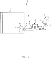
- Fig. 1 shows an arrangement 1 with a water-carrying household appliance 2, in particular a household dishwasher, and a hose device 3.
- the hose device 3 comprises a first connection 4 which is connected to a water supply network 5, in particular a tap or faucet of the water supply network 5.
- the hose device 3 comprises a second connection 6, which is connected to a connection element 7 of the domestic appliance 2.
- the first connection 4 and the second connection 6 are connected to one another by means of a single-walled hose 8.
- the hose 8 is the only hose between the connections 4, 6 and is also not double-walled.
- the single-walled hose 8 thus creates a fluid connection between the water supply network 5 and the household appliance 2.
- the hose 8 is designed as a corrugated hose.
- the hose device 3 is formed between the first connection 4 and the corrugated hose 8 without a safety valve for shutting off a flow of water into the corrugated hose 8 in the event of a leak from the latter.
- a pressure reducer 10 (shown in dashed lines) is provided within the first connection 4 in order to reduce pressure surges 11 (in Fig. 2 shown) from the water supply network 5 to reduce in the corrugated hose 8.
- the corrugated hose 8 can be protected and a safety valve in the hose device 3 can be dispensed with. Only the household appliance 2 has at least one valve 50 in order to interrupt a flow of fresh water into the household appliance 2.
- the household appliance 2 could also be designed as a washing machine, coffee machine or water dispenser.
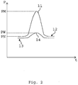
- Fig. 2 shows a schematic pressure-time diagram.
- a pressure P is plotted over a time t.
- a qualitative pressure curve 12 which is present on the water pipe network 5, is shown.
- the pressure curve 12 has a sudden increase in pressure, namely a pressure surge 11.
- the pressure surge 11 has, for example, a brief peak pressure PM greater than 15, 20, 30, 40 or 60 bar.
- a nominal pressure PN is clearly exceeded, for example by a factor of 5, 7 or 10.
- the nominal pressure PN is, for example, between 3 and 7 bar, in particular 5 or 6 bar.
- a pressure profile 13 which is present inside the corrugated hose 8, is plotted over time t. It can be seen here that only a slight increase in pressure 14 occurs in the corrugated hose 8 due to the pressure surge 11.
- the pressure reducer 10 is set up to reduce a pressure PW of the pressure surge 14 in the corrugated hose 8 to below 50%, 40% or 30% of the peak pressure PM of the corresponding pressure surge 11 in the water pipe network 5 and / or the pressure PW of the pressure surge 14 in the corrugated hose 8 to below 30, 20, 15, 12, 10, 8 or 6 bar.
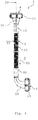
- Fig. 3 shows the hose device 3, in particular from FIG Fig. 1 , in a side view.
- the first connection 4 comprises a nut 15 which is rotatably mounted on a connector 16 of the first connection 4.
- the nut 15 comprises an internal thread (not shown) which can be screwed onto an external thread of a tap of the water supply network 5.
- the connector 16 is connected to a connecting section 17 of the corrugated hose 8.
- a Such a connection is designed, for example, as a plug connection and / or a non-positive connection.
- the connector 16 is connected to the connecting section 17 by means of cold pressing.
- the second connection 6 comprises a nut 18 which is rotatably mounted on a connector 19 of the second connection 6.
- the connector 19 is connected to a connecting section 20 of the corrugated hose 8.
- Such a connection can also be designed as a plug connection and / or a non-positive connection.
- the connector 19 is connected to the connecting section 20 by means of cold pressing.
- a corrugated section 21 of the corrugated hose 8 is formed between the connecting sections 17, 20.
- the two connecting sections 17, 20 are integrally formed on the corrugated section 21.
- the corrugated section 21 includes wave crests and wave troughs (see reference numerals 26 and 27 in Fig. 4 ), which alternate along an extension direction of the corrugated section 21 or the flow direction R1.
- a corrugated contour is formed both on an inside 28 of the corrugated hose 8, which comes into contact with the fresh water, and on an outside 29, which faces the surroundings 9.
- the connector 16 of the first connection is essentially rotationally symmetrical.
- the connector 19 of the second connection 6 has a curvature of approximately 90 °.
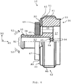
- Fig. 4 shows section IV Fig. 3 .
- the connector 16 comprises a base section 22 which tapers and to which a connecting section 23 connects, which engages in the connecting section 17 of the corrugated hose 8.
- the connecting section 23 is formed in one piece with the base section 22. Furthermore, the connecting section 23 has a tubular shape with a constant inner diameter D2.
- the connecting sections 17 and 23 are firmly connected to one another by means of cold pressing.
- the connector 16 further comprises an annular projection 24 which positively engages in a recess in the nut 15.
- the pressure reducer 10 (in Fig. 4 shown only schematically) is arranged within the base section 22.
- a flow direction R1 of the fresh water points from the nut 15 to the corrugated section 21.
- a sieve 25 is arranged in front of the pressure reducer 10 in the flow direction R1. The sieve 25 filters the water before it can get into the corrugated hose 8.
- the nut 15 comprises an inlet cross-sectional area A1 for a water inlet
- the connecting section 23 comprises an outlet cross-sectional area A2 for a water outlet
- the inlet cross-sectional area A1 being at least 9, 12, 15 or 20 times larger than the outlet cross-sectional area A2.
- the inlet cross-sectional area A1 and the outlet cross-sectional area A2 are circular, with a diameter D1 of the inlet cross-sectional area A1 being at least 3, 4, 4, 5 or 5 times larger than a diameter D2 of the outlet cross-sectional area A2.
- the diameter D1 of the inlet cross-sectional area A1 is between 16 and 20 mm or 17 and 19 mm, in particular 18 mm, and / or the diameter D2 of the outlet cross-sectional area A2 is between 3 and 5 mm, in particular 4 mm.
- Such a taper, in particular of the base section 22, can achieve an additional reduction in pressure surges 11 or an alternative reduction in pressure surges in the event of a malfunction of the pressure reducer 10.
- An inside diameter d3 of the corrugated hose 8 is between 6 and 10 mm or 7 and 9 mm, in particular 8 mm.
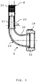
- Fig. 5 shows an in Fig. 3 section, not shown, which runs through the second connection 6 and a section of the corrugated hose 8 adjacent thereto.
- the connector 19 comprises a base section 30, onto which a tubular connecting section 31 with a substantially constant inner diameter D4 is formed, which protrudes into the connecting section 20 of the corrugated hose 8.
- the inside diameter D4 is, for example, between 3 and 5 mm, in particular 4 mm.
- a connection between the connecting sections 20, 31 is designed as a plug connection and / or a force-fit connection.
- the connecting sections 20, 31 are connected to one another by means of cold pressing.
- an annular projection 32 is integrally formed on the base section 30, which protrusion engages in a recess in the nut 18 so that the nut 18 can be rotated relative to the connector 19.
- the base section 30 is curved by 90 °, so that water which flows through the base section 30 changes direction by 90 °. Furthermore, the base section 30 widens from the connecting section 31 towards the nut 18.
- Fig. 6 shows the, especially in Fig. 1 indicated, pressure reducer 10 in a half section.
- the pressure reducer 10 comprises a disk section 33 with a disk wall 51 which extends in a radial direction R2.
- the radial direction R2 runs perpendicular to the flow direction R1.
- a tube section 34 is formed on the disk section 33 and extends counter to the flow direction R1.
- an annular projection 35 is provided, which protrudes in the radial direction R2.
- the disk section 33 has a disk-shaped recess 37 on a side 36 facing away from the tube section 34.
- the disk wall 51 has an outer through opening 38 which runs in the flow direction R1 and is provided radially outside of the pipe section 34.
- the outer through opening 38 runs from a side 39 of the disk section 33 facing the tube section 34 to the side 36.
- the outer through opening 38 opens into the recess 37.
- An annular section 40 is formed on the disk wall 51, which is arranged radially outside the through openings 38 and extends against the flow direction R1.
- an external thread 41 is provided on a radially outer side 42 of the disk section 33 on the disk wall 51.
- a channel 43 runs through the pipe section 34 to the disk section 33, a wall 44 of the disk section 33 separating the channel 43 from the recess 37.
- the wall 44 comprises an inner opening 45 which runs in the flow direction R1 and creates a fluid connection between the channel 43 and the recess 37.
- the inner opening 45 is arranged radially inside the tube section 34.
- the disk wall 51 can comprise a plurality of outer openings 38 for the passage of water to the corrugated hose 8.
- the wall 44 can comprise a multiplicity of inner openings 45 for the passage of water to the corrugated hose 8.
- the channel 43 has a flow cross section A3.
- the inner opening 45 or all inner openings 45 (in the case of several) has / have a flow cross section A4.
- the flow cross section A3 is significantly larger than the flow cross section A4, so that water flowing from the channel 43 into the inner opening 45 or inner openings 45 has to overcome a reduction in the flow cross section.
- a regulating element 46 is arranged on the ring section 34. As in Fig. 6 is shown, the control element 46 is arranged on the side 39 of the disk portion 33. A circumferential flow cross-sectional area A5 is formed between the regulating element 46 and a surface 47 of the ring section 40 that faces the regulating element 46. Water that flows around the pipe section 34 and the regulating element 46 (indicated by parallel arrows 52) must pass through the flow cross-section A5 in order to reach the opening 38 and to flow through it.
- the regulating element 46 is designed to reduce the flow cross section A5 within the first connection 4 in order to reduce pressure surges 14 in the corrugated hose 8 by means of an elastic movement and / or axial movement.
- the control element 46 is designed as a disk that is designed to be elastically deformable and axially movable. By means of an elastic deformation and / or axial movement of the control element 46 in the flow direction R1, the control element 46 is pressed against the surface 47, so that the flow cross-section A5 is also reduced.
- the regulating element 46 comprises, for example, silicone and / or a ceramic material.
- the regulating element 46 is designed in particular to reduce and / or prevent a flow of water through the outer openings 38 in order to reduce pressure surges 11 in the corrugated hose.
- the pressure reducer 10 is screwed into the first connection 4 by means of the thread 41.
- Fig. 7 shows in particular the pressure reducer 10 from Fig. 6 in a side view.
- the ring section 40 comprises a recess 48 which runs in the flow direction R1 and over an entire radial width (not shown) of the ring section.
- the recess 48 and the regulating element 46 define a radial channel 49. Water which flows around the pipe section 34 flows through the radial channel 49 to the outer opening 38.
- the pressure reducer 10 can comprise a plurality of recesses 48 and thus a plurality of radial ones Form channels 49.
- the control element 46 can be pressed against the surface 47 in such a way that the flow cross-section A5 is only defined by radial channels 49.
- the flow area A4 which is defined by the opening 45, cannot be reduced by means of the regulating element 46 will.
- the flow cross section A4 guarantees a minimum flow rate of 2.5 l / min (liters per minute).
- the pressure reducer 10 is set up to form a plurality of radial channels 49 when the pressure surge 11 occurs in the water supply network 5 and thereby reduce the pressure surge 14 in the corrugated hose 8. Furthermore, the pressure reducer 10 is especially designed to reduce the radial channels 49 by means of elastic deformation of the control element 46 when the pressure surge 11 occurs in the water supply network 5 and thereby further reduce the pressure surge 14 in the corrugated hose 8. In this case, the regulating element 46 is pressed into the depressions 48, for example, and the flow cross section A5 is thereby further reduced.
- Fig. 8 shows the pressure reducer 10 without the control element 46 in a perspective view. It can be seen that a large number of outer openings 38, in particular eight outer openings 38, are provided. In particular, one, two, three or four inner openings 45 are provided (not shown). In addition, four depressions 48 are formed on the ring section 40. Therefore, four radial channels 49 can be formed by cooperation with the regulating element 46.
- the thread 41 is in Fig. 8 not shown.
- a curved connector can be provided on the first connection 4.
- a rotationally symmetrical connector without a curvature can be provided on the second connection 6.
- the pressure reducer 10 can also be formed in the nut 15 or in the connecting piece 17 of the corrugated hose 8.
Landscapes
- Engineering & Computer Science (AREA)
- Water Supply & Treatment (AREA)
- Rigid Pipes And Flexible Pipes (AREA)
Priority Applications (2)
| Application Number | Priority Date | Filing Date | Title |
|---|---|---|---|
| PL17177250T PL3418436T3 (pl) | 2017-06-21 | 2017-06-21 | Urządzenie wężowe i układ |
| EP17177250.2A EP3418436B1 (de) | 2017-06-21 | 2017-06-21 | Schlauchvorrichtung und anordnung |
Applications Claiming Priority (1)
| Application Number | Priority Date | Filing Date | Title |
|---|---|---|---|
| EP17177250.2A EP3418436B1 (de) | 2017-06-21 | 2017-06-21 | Schlauchvorrichtung und anordnung |
Publications (2)
| Publication Number | Publication Date |
|---|---|
| EP3418436A1 EP3418436A1 (de) | 2018-12-26 |
| EP3418436B1 true EP3418436B1 (de) | 2021-01-06 |
Family
ID=59215537
Family Applications (1)
| Application Number | Title | Priority Date | Filing Date |
|---|---|---|---|
| EP17177250.2A Active EP3418436B1 (de) | 2017-06-21 | 2017-06-21 | Schlauchvorrichtung und anordnung |
Country Status (2)
| Country | Link |
|---|---|
| EP (1) | EP3418436B1 (pl) |
| PL (1) | PL3418436T3 (pl) |
Families Citing this family (2)
| Publication number | Priority date | Publication date | Assignee | Title |
|---|---|---|---|---|
| DE102020120724A1 (de) | 2020-08-06 | 2022-02-10 | Miele & Cie. Kg | Wasserschutzeinrichtung für ein wasserführendes Haushaltsgerät |
| CN112323355A (zh) * | 2020-10-16 | 2021-02-05 | 天津海尔洗涤电器有限公司 | 一种衣物处理设备及其进水组件 |
Family Cites Families (4)
| Publication number | Priority date | Publication date | Assignee | Title |
|---|---|---|---|---|
| IT1284674B1 (it) * | 1996-07-16 | 1998-05-21 | Eltek Spa | Sistema per la regolazione di un fluido. |
| IT249526Y1 (it) * | 2000-05-29 | 2003-05-19 | Eltek Spa | Dispositivo di caricamento di liquido in un apparato domestico, inparticolare una macchina di lavaggio. |
| ITTO20050876A1 (it) | 2005-12-15 | 2007-06-16 | Eltek Spa | Dispositivo di sicurezza antiallagamento per elettrodomestici, in particolare macchine di lavaggio |
| KR20160031596A (ko) * | 2014-09-12 | 2016-03-23 | 동부대우전자 주식회사 | 감압 및 필터 기능을 갖는 세탁기 급수밸브용 통합장치 및 그 제조방법 |
-
2017
- 2017-06-21 PL PL17177250T patent/PL3418436T3/pl unknown
- 2017-06-21 EP EP17177250.2A patent/EP3418436B1/de active Active
Also Published As
| Publication number | Publication date |
|---|---|
| PL3418436T3 (pl) | 2021-07-05 |
| EP3418436A1 (de) | 2018-12-26 |
Similar Documents
| Publication | Publication Date | Title |
|---|---|---|
| EP3134792B1 (de) | Druckreduzierventil | |
| EP1516237B1 (de) | Durchflussmengenregler | |
| EP3108168B1 (de) | Sicherheitsventil | |
| DE102014005854B4 (de) | Druckreduzierventil | |
| WO2016142021A1 (de) | In einen rohrabschnitt über presspassung einsetzbares bauteil | |
| EP3418436B1 (de) | Schlauchvorrichtung und anordnung | |
| EP2710287B1 (de) | Schlauchverbindungsanordnung | |
| WO2004053368A1 (de) | Rückflussverhinderer | |
| DE102014002175B3 (de) | Sicherheitsventil | |
| EP2459912B1 (de) | Gasströmungswächter | |
| EP3688238B1 (de) | Rückflussverhinderer und systemtrenner insbesondere für den feuerwehrbereich | |
| EP3268543B1 (de) | Sanitäre einsetzeinheit | |
| EP2821730B1 (de) | Anschlussstück sowie Montagesatz | |
| EP3617569B1 (de) | Anschlussarmatur sowie wasserleitungssystem | |
| DE112015000242B4 (de) | Druckreduzier-Ventil für eine Löschanlage sowie Löschanlage mit einem derartigen Druckreduzier-Ventil | |
| EP3048205B1 (de) | Systemtrenneranordnung | |
| DE102006059471B4 (de) | Strömungswächter | |
| DE202013104285U1 (de) | Systemtrenneranordnung | |
| DE102013203570A1 (de) | Schraubanordnung | |
| EP2252817B1 (de) | Gasströmungswächter | |
| DE102007010472B4 (de) | Sanitäre Niederdruckarmatur | |
| DE10117561B4 (de) | Vorrichtung zum automatischen Absperren eines Gasstromes in einem Leitungssystem | |
| EP3683367B1 (de) | Waschbeckenmontageanordnung sowie verfahren zum zusammenbau einer waschbeckenmontageanordnung | |
| EP1798351A2 (de) | Rückflussverhinderer | |
| DE10162604A1 (de) | Heizkörperventil |
Legal Events
| Date | Code | Title | Description |
|---|---|---|---|
| PUAI | Public reference made under article 153(3) epc to a published international application that has entered the european phase |
Free format text: ORIGINAL CODE: 0009012 |
|
| STAA | Information on the status of an ep patent application or granted ep patent |
Free format text: STATUS: THE APPLICATION HAS BEEN PUBLISHED |
|
| AK | Designated contracting states |
Kind code of ref document: A1 Designated state(s): AL AT BE BG CH CY CZ DE DK EE ES FI FR GB GR HR HU IE IS IT LI LT LU LV MC MK MT NL NO PL PT RO RS SE SI SK SM TR |
|
| AX | Request for extension of the european patent |
Extension state: BA ME |
|
| STAA | Information on the status of an ep patent application or granted ep patent |
Free format text: STATUS: REQUEST FOR EXAMINATION WAS MADE |
|
| 17P | Request for examination filed |
Effective date: 20190613 |
|
| RBV | Designated contracting states (corrected) |
Designated state(s): AL AT BE BG CH CY CZ DE DK EE ES FI FR GB GR HR HU IE IS IT LI LT LU LV MC MK MT NL NO PL PT RO RS SE SI SK SM TR |
|
| RIC1 | Information provided on ipc code assigned before grant |
Ipc: D06F 39/08 20060101AFI20200618BHEP Ipc: A47L 15/42 20060101ALI20200618BHEP |
|
| GRAP | Despatch of communication of intention to grant a patent |
Free format text: ORIGINAL CODE: EPIDOSNIGR1 |
|
| STAA | Information on the status of an ep patent application or granted ep patent |
Free format text: STATUS: GRANT OF PATENT IS INTENDED |
|
| INTG | Intention to grant announced |
Effective date: 20200724 |
|
| GRAS | Grant fee paid |
Free format text: ORIGINAL CODE: EPIDOSNIGR3 |
|
| GRAA | (expected) grant |
Free format text: ORIGINAL CODE: 0009210 |
|
| STAA | Information on the status of an ep patent application or granted ep patent |
Free format text: STATUS: THE PATENT HAS BEEN GRANTED |
|
| AK | Designated contracting states |
Kind code of ref document: B1 Designated state(s): AL AT BE BG CH CY CZ DE DK EE ES FI FR GB GR HR HU IE IS IT LI LT LU LV MC MK MT NL NO PL PT RO RS SE SI SK SM TR |
|
| REG | Reference to a national code |
Ref country code: GB Ref legal event code: FG4D Free format text: NOT ENGLISH |
|
| REG | Reference to a national code |
Ref country code: AT Ref legal event code: REF Ref document number: 1352484 Country of ref document: AT Kind code of ref document: T Effective date: 20210115 Ref country code: CH Ref legal event code: EP |
|
| REG | Reference to a national code |
Ref country code: DE Ref legal event code: R096 Ref document number: 502017008919 Country of ref document: DE |
|
| REG | Reference to a national code |
Ref country code: IE Ref legal event code: FG4D Free format text: LANGUAGE OF EP DOCUMENT: GERMAN |
|
| RAP2 | Party data changed (patent owner data changed or rights of a patent transferred) |
Owner name: BSH HAUSGERAETE GMBH |
|
| REG | Reference to a national code |
Ref country code: NL Ref legal event code: MP Effective date: 20210106 |
|
| REG | Reference to a national code |
Ref country code: LT Ref legal event code: MG9D |
|
| PG25 | Lapsed in a contracting state [announced via postgrant information from national office to epo] |
Ref country code: HR Free format text: LAPSE BECAUSE OF FAILURE TO SUBMIT A TRANSLATION OF THE DESCRIPTION OR TO PAY THE FEE WITHIN THE PRESCRIBED TIME-LIMIT Effective date: 20210106 Ref country code: FI Free format text: LAPSE BECAUSE OF FAILURE TO SUBMIT A TRANSLATION OF THE DESCRIPTION OR TO PAY THE FEE WITHIN THE PRESCRIBED TIME-LIMIT Effective date: 20210106 Ref country code: GR Free format text: LAPSE BECAUSE OF FAILURE TO SUBMIT A TRANSLATION OF THE DESCRIPTION OR TO PAY THE FEE WITHIN THE PRESCRIBED TIME-LIMIT Effective date: 20210407 Ref country code: PT Free format text: LAPSE BECAUSE OF FAILURE TO SUBMIT A TRANSLATION OF THE DESCRIPTION OR TO PAY THE FEE WITHIN THE PRESCRIBED TIME-LIMIT Effective date: 20210506 Ref country code: NO Free format text: LAPSE BECAUSE OF FAILURE TO SUBMIT A TRANSLATION OF THE DESCRIPTION OR TO PAY THE FEE WITHIN THE PRESCRIBED TIME-LIMIT Effective date: 20210406 Ref country code: BG Free format text: LAPSE BECAUSE OF FAILURE TO SUBMIT A TRANSLATION OF THE DESCRIPTION OR TO PAY THE FEE WITHIN THE PRESCRIBED TIME-LIMIT Effective date: 20210406 Ref country code: LT Free format text: LAPSE BECAUSE OF FAILURE TO SUBMIT A TRANSLATION OF THE DESCRIPTION OR TO PAY THE FEE WITHIN THE PRESCRIBED TIME-LIMIT Effective date: 20210106 |
|
| PG25 | Lapsed in a contracting state [announced via postgrant information from national office to epo] |
Ref country code: SE Free format text: LAPSE BECAUSE OF FAILURE TO SUBMIT A TRANSLATION OF THE DESCRIPTION OR TO PAY THE FEE WITHIN THE PRESCRIBED TIME-LIMIT Effective date: 20210106 Ref country code: LV Free format text: LAPSE BECAUSE OF FAILURE TO SUBMIT A TRANSLATION OF THE DESCRIPTION OR TO PAY THE FEE WITHIN THE PRESCRIBED TIME-LIMIT Effective date: 20210106 Ref country code: RS Free format text: LAPSE BECAUSE OF FAILURE TO SUBMIT A TRANSLATION OF THE DESCRIPTION OR TO PAY THE FEE WITHIN THE PRESCRIBED TIME-LIMIT Effective date: 20210106 |
|
| PG25 | Lapsed in a contracting state [announced via postgrant information from national office to epo] |
Ref country code: IS Free format text: LAPSE BECAUSE OF FAILURE TO SUBMIT A TRANSLATION OF THE DESCRIPTION OR TO PAY THE FEE WITHIN THE PRESCRIBED TIME-LIMIT Effective date: 20210506 |
|
| REG | Reference to a national code |
Ref country code: DE Ref legal event code: R097 Ref document number: 502017008919 Country of ref document: DE |
|
| PG25 | Lapsed in a contracting state [announced via postgrant information from national office to epo] |
Ref country code: CZ Free format text: LAPSE BECAUSE OF FAILURE TO SUBMIT A TRANSLATION OF THE DESCRIPTION OR TO PAY THE FEE WITHIN THE PRESCRIBED TIME-LIMIT Effective date: 20210106 Ref country code: EE Free format text: LAPSE BECAUSE OF FAILURE TO SUBMIT A TRANSLATION OF THE DESCRIPTION OR TO PAY THE FEE WITHIN THE PRESCRIBED TIME-LIMIT Effective date: 20210106 Ref country code: SM Free format text: LAPSE BECAUSE OF FAILURE TO SUBMIT A TRANSLATION OF THE DESCRIPTION OR TO PAY THE FEE WITHIN THE PRESCRIBED TIME-LIMIT Effective date: 20210106 |
|
| PLBE | No opposition filed within time limit |
Free format text: ORIGINAL CODE: 0009261 |
|
| STAA | Information on the status of an ep patent application or granted ep patent |
Free format text: STATUS: NO OPPOSITION FILED WITHIN TIME LIMIT |
|
| PG25 | Lapsed in a contracting state [announced via postgrant information from national office to epo] |
Ref country code: DK Free format text: LAPSE BECAUSE OF FAILURE TO SUBMIT A TRANSLATION OF THE DESCRIPTION OR TO PAY THE FEE WITHIN THE PRESCRIBED TIME-LIMIT Effective date: 20210106 Ref country code: RO Free format text: LAPSE BECAUSE OF FAILURE TO SUBMIT A TRANSLATION OF THE DESCRIPTION OR TO PAY THE FEE WITHIN THE PRESCRIBED TIME-LIMIT Effective date: 20210106 Ref country code: SK Free format text: LAPSE BECAUSE OF FAILURE TO SUBMIT A TRANSLATION OF THE DESCRIPTION OR TO PAY THE FEE WITHIN THE PRESCRIBED TIME-LIMIT Effective date: 20210106 |
|
| 26N | No opposition filed |
Effective date: 20211007 |
|
| PG25 | Lapsed in a contracting state [announced via postgrant information from national office to epo] |
Ref country code: AL Free format text: LAPSE BECAUSE OF FAILURE TO SUBMIT A TRANSLATION OF THE DESCRIPTION OR TO PAY THE FEE WITHIN THE PRESCRIBED TIME-LIMIT Effective date: 20210106 Ref country code: MC Free format text: LAPSE BECAUSE OF FAILURE TO SUBMIT A TRANSLATION OF THE DESCRIPTION OR TO PAY THE FEE WITHIN THE PRESCRIBED TIME-LIMIT Effective date: 20210106 Ref country code: ES Free format text: LAPSE BECAUSE OF FAILURE TO SUBMIT A TRANSLATION OF THE DESCRIPTION OR TO PAY THE FEE WITHIN THE PRESCRIBED TIME-LIMIT Effective date: 20210106 |
|
| REG | Reference to a national code |
Ref country code: CH Ref legal event code: PL |
|
| GBPC | Gb: european patent ceased through non-payment of renewal fee |
Effective date: 20210621 |
|
| PG25 | Lapsed in a contracting state [announced via postgrant information from national office to epo] |
Ref country code: SI Free format text: LAPSE BECAUSE OF FAILURE TO SUBMIT A TRANSLATION OF THE DESCRIPTION OR TO PAY THE FEE WITHIN THE PRESCRIBED TIME-LIMIT Effective date: 20210106 |
|
| REG | Reference to a national code |
Ref country code: BE Ref legal event code: MM Effective date: 20210630 |
|
| PG25 | Lapsed in a contracting state [announced via postgrant information from national office to epo] |
Ref country code: LU Free format text: LAPSE BECAUSE OF NON-PAYMENT OF DUE FEES Effective date: 20210621 |
|
| PG25 | Lapsed in a contracting state [announced via postgrant information from national office to epo] |
Ref country code: LI Free format text: LAPSE BECAUSE OF NON-PAYMENT OF DUE FEES Effective date: 20210630 Ref country code: IT Free format text: LAPSE BECAUSE OF FAILURE TO SUBMIT A TRANSLATION OF THE DESCRIPTION OR TO PAY THE FEE WITHIN THE PRESCRIBED TIME-LIMIT Effective date: 20210106 Ref country code: IE Free format text: LAPSE BECAUSE OF NON-PAYMENT OF DUE FEES Effective date: 20210621 Ref country code: GB Free format text: LAPSE BECAUSE OF NON-PAYMENT OF DUE FEES Effective date: 20210621 Ref country code: CH Free format text: LAPSE BECAUSE OF NON-PAYMENT OF DUE FEES Effective date: 20210630 |
|
| PG25 | Lapsed in a contracting state [announced via postgrant information from national office to epo] |
Ref country code: IS Free format text: LAPSE BECAUSE OF FAILURE TO SUBMIT A TRANSLATION OF THE DESCRIPTION OR TO PAY THE FEE WITHIN THE PRESCRIBED TIME-LIMIT Effective date: 20210506 Ref country code: FR Free format text: LAPSE BECAUSE OF NON-PAYMENT OF DUE FEES Effective date: 20210630 |
|
| PG25 | Lapsed in a contracting state [announced via postgrant information from national office to epo] |
Ref country code: BE Free format text: LAPSE BECAUSE OF NON-PAYMENT OF DUE FEES Effective date: 20210630 |
|
| PG25 | Lapsed in a contracting state [announced via postgrant information from national office to epo] |
Ref country code: NL Free format text: LAPSE BECAUSE OF NON-PAYMENT OF DUE FEES Effective date: 20210206 Ref country code: CY Free format text: LAPSE BECAUSE OF FAILURE TO SUBMIT A TRANSLATION OF THE DESCRIPTION OR TO PAY THE FEE WITHIN THE PRESCRIBED TIME-LIMIT Effective date: 20210106 |
|
| PG25 | Lapsed in a contracting state [announced via postgrant information from national office to epo] |
Ref country code: HU Free format text: LAPSE BECAUSE OF FAILURE TO SUBMIT A TRANSLATION OF THE DESCRIPTION OR TO PAY THE FEE WITHIN THE PRESCRIBED TIME-LIMIT; INVALID AB INITIO Effective date: 20170621 |
|
| REG | Reference to a national code |
Ref country code: AT Ref legal event code: MM01 Ref document number: 1352484 Country of ref document: AT Kind code of ref document: T Effective date: 20220621 |
|
| PG25 | Lapsed in a contracting state [announced via postgrant information from national office to epo] |
Ref country code: AT Free format text: LAPSE BECAUSE OF NON-PAYMENT OF DUE FEES Effective date: 20220621 |
|
| PG25 | Lapsed in a contracting state [announced via postgrant information from national office to epo] |
Ref country code: MK Free format text: LAPSE BECAUSE OF FAILURE TO SUBMIT A TRANSLATION OF THE DESCRIPTION OR TO PAY THE FEE WITHIN THE PRESCRIBED TIME-LIMIT Effective date: 20210106 |
|
| PG25 | Lapsed in a contracting state [announced via postgrant information from national office to epo] |
Ref country code: MT Free format text: LAPSE BECAUSE OF FAILURE TO SUBMIT A TRANSLATION OF THE DESCRIPTION OR TO PAY THE FEE WITHIN THE PRESCRIBED TIME-LIMIT Effective date: 20210106 |
|
| PGFP | Annual fee paid to national office [announced via postgrant information from national office to epo] |
Ref country code: DE Payment date: 20250630 Year of fee payment: 9 Ref country code: PL Payment date: 20250610 Year of fee payment: 9 |
|
| PGFP | Annual fee paid to national office [announced via postgrant information from national office to epo] |
Ref country code: TR Payment date: 20250618 Year of fee payment: 9 |