EP3418090A1 - Register - Google Patents
Register Download PDFInfo
- Publication number
- EP3418090A1 EP3418090A1 EP18175737.8A EP18175737A EP3418090A1 EP 3418090 A1 EP3418090 A1 EP 3418090A1 EP 18175737 A EP18175737 A EP 18175737A EP 3418090 A1 EP3418090 A1 EP 3418090A1
- Authority
- EP
- European Patent Office
- Prior art keywords
- curved surface
- air
- groove
- ridge
- approximately
- Prior art date
- Legal status (The legal status is an assumption and is not a legal conclusion. Google has not performed a legal analysis and makes no representation as to the accuracy of the status listed.)
- Withdrawn
Links
Images




Classifications
-
- B—PERFORMING OPERATIONS; TRANSPORTING
- B60—VEHICLES IN GENERAL
- B60H—ARRANGEMENTS OF HEATING, COOLING, VENTILATING OR OTHER AIR-TREATING DEVICES SPECIALLY ADAPTED FOR PASSENGER OR GOODS SPACES OF VEHICLES
- B60H1/00—Heating, cooling or ventilating devices
- B60H1/34—Nozzles; Air-diffusers
- B60H1/3414—Nozzles; Air-diffusers with means for adjusting the air stream direction
- B60H1/3421—Nozzles; Air-diffusers with means for adjusting the air stream direction using only pivoting shutters
-
- F—MECHANICAL ENGINEERING; LIGHTING; HEATING; WEAPONS; BLASTING
- F24—HEATING; RANGES; VENTILATING
- F24F—AIR-CONDITIONING; AIR-HUMIDIFICATION; VENTILATION; USE OF AIR CURRENTS FOR SCREENING
- F24F13/00—Details common to, or for air-conditioning, air-humidification, ventilation or use of air currents for screening
- F24F13/08—Air-flow control members, e.g. louvres, grilles, flaps or guide plates
- F24F13/10—Air-flow control members, e.g. louvres, grilles, flaps or guide plates movable, e.g. dampers
- F24F13/14—Air-flow control members, e.g. louvres, grilles, flaps or guide plates movable, e.g. dampers built up of tilting members, e.g. louvre
- F24F13/1413—Air-flow control members, e.g. louvres, grilles, flaps or guide plates movable, e.g. dampers built up of tilting members, e.g. louvre using more than one tilting member, e.g. with several pivoting blades
-
- B—PERFORMING OPERATIONS; TRANSPORTING
- B60—VEHICLES IN GENERAL
- B60H—ARRANGEMENTS OF HEATING, COOLING, VENTILATING OR OTHER AIR-TREATING DEVICES SPECIALLY ADAPTED FOR PASSENGER OR GOODS SPACES OF VEHICLES
- B60H1/00—Heating, cooling or ventilating devices
- B60H1/34—Nozzles; Air-diffusers
- B60H2001/3471—Details of actuators
-
- B—PERFORMING OPERATIONS; TRANSPORTING
- B60—VEHICLES IN GENERAL
- B60H—ARRANGEMENTS OF HEATING, COOLING, VENTILATING OR OTHER AIR-TREATING DEVICES SPECIALLY ADAPTED FOR PASSENGER OR GOODS SPACES OF VEHICLES
- B60H1/00—Heating, cooling or ventilating devices
- B60H1/34—Nozzles; Air-diffusers
- B60H2001/3471—Details of actuators
- B60H2001/3478—Details of actuators acting on additional damper doors
Definitions
- the present invention relates to a register.
- registers each including a horizontally-elongated thin air outlet are known through, e.g., Japanese Patent Application Publication No. 2013-116650 .
- This type of register is configured such that: a bezel fitted to a front portion of a retainer has a vertical width that decreases forward; a horizontally-elongated air outlet is provided in a front surface of the bezel; and a front movable louver is arranged immediately inward of the air outlet.
- a center horizontal fin is disposed horizontally, and an upper auxiliary horizontal fin and a lower auxiliary horizontal fin are disposed in parallel above and below the center horizontal fin, respectively, and these horizontal fins are joined via a link bar, thereby providing a structure in which when the front movable louver is turned to face upward or downward, the respective horizontal fins face the same direction in conjunction with one another.
- the front shape of the above register is inclined such that an upper portion thereof is retracted toward the upstream side and a lower portion thereof projects toward the downstream side, and is thus formed as what is called a slanted shape, and the shape of an instrument panel in which the register is installed is curved so as to bulge forward, below the area in front of the air outlet of the register, and thus, a structure in which a ledge portion is located below the area in front of the air outlet is provided.
- a register having a structure in which a special bottom portion auxiliary fin is pivotally supported at an inner bottom portion of the air outlet so as to be capable of turning and projecting upward, and when the front movable louver is turned toward the upper side relative to the front neutral position, the bottom portion auxiliary fin is drawn out upward to prevent an air blow sticking phenomenon due to the Coanda effect at the ledge portion ahead.
- the present invention provides a register including a bulging curved ledge portion located below an area in front of an air outlet, the register enabling suppression of an air blow sticking phenomenon by a simple structure.
- a register includes: an air outlet; a front movable louver disposed inward of the air outlet, the front movable louver turning vertically; and a bulging curved ledge portion disposed below an area in front of the air outlet, wherein the ledge portion includes a curved surface that curves downward ahead, and a groove or a ridge for disturbing the flow of air along the curved surface is provided in parallel with a longitudinal direction of the front movable louver, in the curved surface.
- the bulging curved ledge portion is disposed below the area in front of the air outlet and air blowing forward from the air outlet tends to flow so as to stick to the curved surface at the end portion because of the Coanda effect, but since a groove or a ridge is formed in parallel with the longitudinal direction of the front fin, in the curved surface of the ledge portion, the flow of the air along the curved surface is disturbed by the groove or the ridge.
- the air flow sticking to the curved surface of the ledge portion is decreased, and thus, the air can be made to blow straight along the direction of the front fin, that is, toward the lower side ahead (direction toward the lower region of an occupant), with good directivity. Furthermore, the bulging curved ledge portion is located below the area in front of the air outlet and the directivity of the blowing air is thus favorable, and thus, the air blow direction can easily be adjusted to the lower side just by slightly turning the front movable louver downward.
- the curved surface of the ledge portion may be formed so as to be integrated with a horizontal surface, the curved surface extending forward from the horizontal surface, and the groove or the ridge may be formed in parallel with a longitudinal direction of a front fin, in a vicinity, on the horizontal surface side, of the curved surface. Accordingly, while the design of the ledge portion being maintained in a favorable manner, the air flow sticking to the curved surface of the ledge portion can more effectively be reduced, enabling the air to blow along the direction of the front fin, with good directivity.
- the groove or the ridge may have a triangular shape in cross-section. In the above aspect, the groove or the ridge may have a rectangular shape in cross-section. In the above aspect, the groove or the ridge may have a semicircular shape in cross-section.
- a depth of the groove or a height of the ridge may be approximately 1.5 mm to approximately 2 mm; and a width in a cross-sectional direction of the groove or the ridge may be approximately 2 mm to 4 mm.
- a width, along an air blow direction, of the ledge portion may be approximately 1.5 times to approximately 3 times a width of the front fin.
- the above aspect enables provision of a register including a bulging curved ledge portion located blow an area in front of an air outlet, the register enabling suppression of an air blow sticking phenomenon by a simple structure and thus improvement in directivity of air toward an occupant.
- a register includes a retainer 1 including an air passageway 9 inside, the retainer 1 being formed in a duct-like shape having a substantially rectangular shape in section, a bezel 2 attached to a front surface of the retainer 1, the bezel 2 including an air outlet 4 formed therein, a front movable louver 10 arranged inward of the air outlet 4, and a rear movable louver 20 inside the air passageway 9 upstream of the front movable louver 10, the rear movable louver 20 being arranged in a direction orthogonal to the front movable louver 10.
- a plate-like attachment portion 2a is provided so as to extend in a lower portion of the bezel 2.
- the ledge portion 3 includes a horizontal portion including a horizontal surface 30, the horizontal portion being provided at an upper portion of the ledge portion 3, and a curved portion of a curved surface 31 that curves in a bulging manner, the curved portion being provided ahead of the horizontal surface 30 of the horizontal portion.
- the curved portion of the ledge portion 3 includes the curved surface 31 that curves in a downward bulging manner.
- the ledge portion 3 is formed in a box-like cover shape, and is attached to the attachment portion 2a in the lower portion of the bezel 2 by fitting a back side portion of the ledge portion 3 to the attachment portion 2a from the front side. Consequently, as illustrated in FIG. 7 , the horizontal surface 30 of the ledge portion 3 is located immediately below an area in front of the air outlet 4 of the bezel 2, and the curved surface 31 that curves downward is provided so as to extend ahead of the horizontal surface 30, and a vertical surface 33 is provided so as to extend below the curved surface 31. As described later, in the curved surface 31, one groove 32 is provided in parallel with a longitudinal direction of front fins 11 of the front movable louver 10, that is, a direction perpendicular to a direction of air blowing from the air outlet 4.
- the front movable louver 10 is provided immediately inward of the air outlet 4 in the bezel 2 so as to vertically change the air blow direction.
- the front movable louver 10 includes three front fins 11, and a side pivot support member 7 that pivotally supports pivots 12 of respective one end portions of the front fins 11, and as illustrated in FIG. 9 , pivots 12 at the one end portions of the front fins 11 are fitted in respective bearing holes 7a provided in the side pivot support member 7, whereby the front fins 11 are supported so as to be turnable vertically.
- Pivots 12 at the respective other end portions of the front fins 11 are fitted in, and are thereby pivotally supported by, respective bearing holes provided in a side portion of the retainer 1.
- link shafts 15 are provided at the respective other end portions of the three front fins 11, and the link shafts 15 are joined to a single link bar 16.
- guide projection portions 14 are provided at the respective one end portions of the front fins 11 so as to project, and as illustrated in FIG. 9 , the guide projection portions 14 engage with guide grooves provided in the side pivot support member 7. Consequently, vertical turning of the front fins 11 is guided, and an angular range of the turning is limited within a predetermined range.
- the rear movable louver 20 is arranged inside the air passageway 9, upstream of the front movable louver 10.
- the rear movable louver 20 includes a plurality of (five) rear fins 21 provided side by side in a direction orthogonal to the front movable louver 10 (vertical direction).
- pivots 22 are provided so as to project from upper and lower portions of each of the rear fins 21 of the rear movable louver 20, and the upper and lower pivots 22 are supported by an upper pivot member 5 and a lower pivot member 6 fitted in the inner side of a front portion of an opening of the retainer 1, respectively, so as to be turnable horizontally.
- a bearing hole 5a is provided in the upper pivot member 5
- a bearing hole 6a is provided in the lower pivot member 6
- the upper pivots 22 of the rear fins 21 are fitted in and thereby supported by the bearing holes 5a of the upper pivot member 5
- the lower pivots 22 are fitted in and thereby supported by the bearing holes 6a of the lower pivot member 6.
- the rear fins 21 of the rear movable louver 20 are supported via the upper and lower pivots 22 so as to be turnable horizontally, and furthermore, a single link bar 25 is linked to the rear fins 21, whereby the five rear fins 21 can turn in synchronization with one another.
- a sector teeth portion 26 is formed in front of the center rear fin 21, and a rack portion 8a provided at a back side portion of an operation knob 8 engages with the sector teeth portion 26.
- the operation knob 8 is externally fitted on a front fin 11 so as to be slidable horizontally.
- a load providing member 8b is held inside the operation knob 8, and a protrusion portion of the load providing member 8b is in abutment with a front end portion of the front fin 11. Consequently, when the operation knob 8 is slid horizontally, an operation load is provided by moderate frictional resistance of the operation load providing member 8b, whereby the rear fins 21 of the rear movable louver 20 turn rightward or leftward and thus turn around.
- the rear movable louver 20 has a structure in which when the operation knob 8 is slide rightward to the maximum, the rear movable louver 20 is brought into a closed state in which all of the rear fins 21 overlap one another to close the air passageway 9.
- the bulging curved ledge portion 3 is attached to the attachment portion 2a in the lower portion of the bezel 2 so as to project forward below the bezel 2.
- the ledge portion 3 includes the horizontal portion including the horizontal surface 30, the horizontal portion being provided at the upper portion of the ledge portion 3, and the curved portion that curves in a downward bulging manner, the curved portion being provided ahead of the horizontal surface 30 of the horizontal portion.
- the curved surface 31 that bulges ahead of the horizontal surface 30 is formed so as to curve downward, and the bulging curved ledge portion 3 is thus formed.
- the vertical surface 33 is formed below the curved surface 31, and the curved surface 31 is provided so as to connect the horizontal surface 30 above and the vertical surface 33 below.
- the single groove 32 is provided in the curved surface 31 in parallel with the longitudinal direction of the front fins 11 of the front movable louver 10, that is, in the direction perpendicular to the direction of air blowing from the air outlet 4.
- the groove 32 is formed so as to have a substantially triangular shape in cross-section.
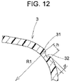
- the groove 32 has a depth d of approximately 1 mm to approximately 2.2 mm, more preferably, approximately 1.5 mm to approximately 2 mm.
- the groove 32 has an opening width h of approximately 1.5 mm to approximately 4.5 mm, more preferably, approximately 2 mm to approximately 4 mm.
- the curved surface 31 is formed in such a manner that a curvature radius R1 of the curved surface 31 is approximately ten to eleven times the depth d of the groove 32. Also, as illustrated in FIG. 8 , the ledge portion 3 including the bulging curved surface 31 is formed so as to have a width W2, along the air blow direction, of approximately 1.5 to 3 times a width W1 of the front fins 11.
- the groove 32 provided in the curved surface 31 is intended to, when air is made to blow forward or obliquely downward from the air outlet 4, disturb the flow of the air along the surface of the ledge portion 3 to prevent a phenomenon of the air flow sticking to the ledge portion surface. Therefore, as illustrated in FIG. 14 , instead of the groove, a single ridge 38 can be provided in the curved surface 31 in parallel with the longitudinal direction of the front fins 11 as long as the single ridge 38 has a function that disturbs the flow of the air along the surface of the ledge portion 3.
- the ridge 38 is formed so as to have a substantially triangular shape in cross-section.
- the ridge 38 can have a height d of approximately 1 mm to approximately 2.2 mm, more preferably approximately 1.5 mm to approximately 2 mm as in the above.
- the ridge 38 can have a width h in the cross-sectional direction of approximately 1.5 mm to approximately 4.5 mm, more preferably, approximately 2 mm to approximately 4 mm.
- FIGS. 15A to 15D each illustrate another example of a cross-sectional shape of a groove or a ridge formed in the curved surface 31.
- the groove formed in the curved surface 31 only needs to have a function that disturbs the flow of air along the surface of the ledge portion 3, and thus, as illustrated in FIG. 15A , may be a groove 34 having a substantially semicircular shape in cross-section, or as illustrated in FIG. 15B , may be a ridge 35 having a substantially semicircular shape in cross-section.
- the groove may be a groove 36 having a substantially rectangular shape in cross-section as illustrated in FIG. 15C , or may be a ridge 37 having a substantially rectangular shape in cross-section as illustrated in FIG. 15D .
- the groove 36 or the ridge 37 can have a height d of approximately 1 mm to approximately 2.2 mm, more preferably, approximately 1.5 mm to approximately 2 mm.
- the groove 36 or the ridge 37 can have a width h in the cross-sectional direction of approximately 1.5 mm to approximately 4.5 mm, more preferably, approximately 2 mm to approximately 4 mm.
- the register is mounted in, for example, an area in the vicinity of an upper portion of, e.g., an instrument panel or a dashboard inside an automobile, with an air inlet on the back surface side connected to a non-illustrated air ventilation duct.
- the air outlet 4 of the bezel 2 of the register is attached so as to be exposed in a front surface of the instrument panel or the dashboard and the air blow direction in the neutral state in FIG. 7 faces, for example, the vicinity of the neck of an occupant.
- the air can be made to blow toward an occupant ahead, with good directivity.
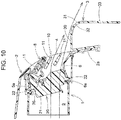
- the front movable louver 10 is turned downward via the operation knob 8. Then, as illustrated in FIG. 10 , the front fins 11 turn (tilt) downward with the respective pivots 12 as axes. Then, the flow of the air to be blown from the air outlet 4 is guided by the front fins 11 so as to be flexed toward the lower side, and as illustrated in FIG. 11 , the air thus flows from the horizontal surface 30 of the ledge portion 3 located below the area in front of the front fins 11 so as to come into contact with the curved surface 31.
- the operation knob 8 is slid rightward or leftward on the relevant front fin 11. Then, the horizontal movement of the operation knob 8 causes the rear movable louver 20 to turn rightward or leftward via the rack portion 8a and the sector teeth portion 26, and the respective rear fins 21 of the rear movable louver 20 thus face obliquely rightward or obliquely leftward, whereby the air blow direction is changed horizontally.
- the air blown out forward from the air outlet 4 tends to flow so as to stick onto the curved surface 31 at an end portion because of the Coanda effect since the bulging curved ledge portion 3 is located below the area in front of the air outlet 4; however, the groove 32 or the ridge 38 is formed in parallel with the longitudinal direction of the front fins 11, in the curved surface 31 of the ledge portion 3, and thus, the flow of the air along the curved surface 31 is disturbed by the groove 32 or the ridge 38.
Landscapes
- Engineering & Computer Science (AREA)
- Mechanical Engineering (AREA)
- Physics & Mathematics (AREA)
- Thermal Sciences (AREA)
- Chemical & Material Sciences (AREA)
- Combustion & Propulsion (AREA)
- General Engineering & Computer Science (AREA)
- Air-Conditioning For Vehicles (AREA)
- Air-Flow Control Members (AREA)
Abstract
Description
- The present invention relates to a register.
- As air blow adjustment registers mounted in, e.g., an instrument panel of an automobile, registers each including a horizontally-elongated thin air outlet are known through, e.g., Japanese Patent Application Publication No.
2013-116650 - However, the front shape of the above register is inclined such that an upper portion thereof is retracted toward the upstream side and a lower portion thereof projects toward the downstream side, and is thus formed as what is called a slanted shape, and the shape of an instrument panel in which the register is installed is curved so as to bulge forward, below the area in front of the air outlet of the register, and thus, a structure in which a ledge portion is located below the area in front of the air outlet is provided.
- Therefore, an air blow sticking phenomenon due to the Coanda effect is likely to occur at the bulging curved portion below the area in front of the register, and upon occurrence of an air blow sticking phenomenon, an air flow along the front movable louver from the air outlet is guided downward, and thus, directivity of the air flow on the upper side relative to the front neutral position is likely to deteriorate. Therefore, a register having a structure in which a special bottom portion auxiliary fin is pivotally supported at an inner bottom portion of the air outlet so as to be capable of turning and projecting upward, and when the front movable louver is turned toward the upper side relative to the front neutral position, the bottom portion auxiliary fin is drawn out upward to prevent an air blow sticking phenomenon due to the Coanda effect at the ledge portion ahead.
- However, it is necessary to draw out or back the bottom portion auxiliary fin upon the front movable louver being turned vertically, and therefore, a mechanism for turning the bottom portion auxiliary fin is complicated, resulting in an increase in number of components, thus, an increase in manufacturing cost.
- The present invention provides a register including a bulging curved ledge portion located below an area in front of an air outlet, the register enabling suppression of an air blow sticking phenomenon by a simple structure.
- A register according to an aspect of the present invention includes: an air outlet; a front movable louver disposed inward of the air outlet, the front movable louver turning vertically; and a bulging curved ledge portion disposed below an area in front of the air outlet, wherein the ledge portion includes a curved surface that curves downward ahead, and a groove or a ridge for disturbing the flow of air along the curved surface is provided in parallel with a longitudinal direction of the front movable louver, in the curved surface.
- With the above aspect, the bulging curved ledge portion is disposed below the area in front of the air outlet and air blowing forward from the air outlet tends to flow so as to stick to the curved surface at the end portion because of the Coanda effect, but since a groove or a ridge is formed in parallel with the longitudinal direction of the front fin, in the curved surface of the ledge portion, the flow of the air along the curved surface is disturbed by the groove or the ridge.
- Consequently, the phenomenon of the air flow sticking to the curved surface is suppressed, and when the front movable louver is turned to face a neutral position (toward the front side) or slightly downward, the air flows toward the front side or slightly downward with good directivity, and thus, improvement in directivity can be achieved by a simple structure, that is, provision of the groove or the ridge.
- When the front fin of the front movable louver is largely turned downward, the air flow sticking to the curved surface of the ledge portion is decreased, and thus, the air can be made to blow straight along the direction of the front fin, that is, toward the lower side ahead (direction toward the lower region of an occupant), with good directivity. Furthermore, the bulging curved ledge portion is located below the area in front of the air outlet and the directivity of the blowing air is thus favorable, and thus, the air blow direction can easily be adjusted to the lower side just by slightly turning the front movable louver downward.
- In the above aspect, the curved surface of the ledge portion may be formed so as to be integrated with a horizontal surface, the curved surface extending forward from the horizontal surface, and the groove or the ridge may be formed in parallel with a longitudinal direction of a front fin, in a vicinity, on the horizontal surface side, of the curved surface. Accordingly, while the design of the ledge portion being maintained in a favorable manner, the air flow sticking to the curved surface of the ledge portion can more effectively be reduced, enabling the air to blow along the direction of the front fin, with good directivity.
- In the above aspect, the groove or the ridge may have a triangular shape in cross-section. In the above aspect, the groove or the ridge may have a rectangular shape in cross-section. In the above aspect, the groove or the ridge may have a semicircular shape in cross-section.
- In the above aspect, a depth of the groove or a height of the ridge may be approximately 1.5 mm to approximately 2 mm; and a width in a cross-sectional direction of the groove or the ridge may be approximately 2 mm to 4 mm.
- In the above aspect, a width, along an air blow direction, of the ledge portion may be approximately 1.5 times to approximately 3 times a width of the front fin.
- The above aspect enables provision of a register including a bulging curved ledge portion located blow an area in front of an air outlet, the register enabling suppression of an air blow sticking phenomenon by a simple structure and thus improvement in directivity of air toward an occupant.
- Features, advantages, and technical and industrial significance of exemplary embodiments of the invention will be described below with reference to the accompanying drawings, in which like numerals denote like elements, and wherein:
-
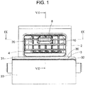
FIG. 1 is a front view of a register according to an embodiment of the present invention; -
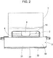
FIG. 2 is a plan view of the register; -
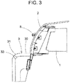
FIG. 3 is a right side view of the register; -
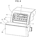
FIG. 4 is a perspective view of the register; -
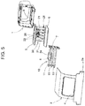
FIG. 5 is an exploded perspective view of the register; -
FIG. 6 is an exploded perspective view of a ledge portion and a bezel; -
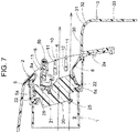
FIG. 7 is a vertical sectional view along VII-VII inFIG. 1 ; -
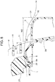
FIG. 8 is an enlarged sectional view of a vicinity of the ledge portion inFIG. 7 ; -
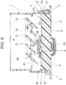
FIG. 9 is a sectional view along IX-IX inFIG. 1 ; -
FIG. 10 is a sectional view corresponding toFIG. 7 when a front movable louver is swung downward; -
FIG. 11 is an enlarged sectional view of the vicinity of the ledge portion inFIG. 10 ; -
FIG. 12 is an enlarged sectional view of a groove of the ledge portion; -
FIG. 13 is a sectional view corresponding toFIG. 9 when a rear movable louver is closed; -
FIG. 14 is an enlarged sectional view of a curved surface of a ledge portion according to another embodiment; -
FIG. 15A is an enlarged sectional view of a curved surface of a ledge portion according to another embodiment; -
FIG. 15B is an enlarged sectional view of a curved surface of a ledge portion according to another embodiment; -
FIG. 15C is an enlarged sectional view of a curved surface of a ledge portion according to another embodiment; and -
FIG. 15D is an enlarged sectional view of a curved surface of a ledge portion according to another embodiment. - Embodiments of the present invention will be described below with reference to the drawings. As illustrated in
FIGS. 1 to 4 , a register includes aretainer 1 including anair passageway 9 inside, theretainer 1 being formed in a duct-like shape having a substantially rectangular shape in section, abezel 2 attached to a front surface of theretainer 1, thebezel 2 including anair outlet 4 formed therein, a frontmovable louver 10 arranged inward of theair outlet 4, and a rearmovable louver 20 inside theair passageway 9 upstream of the frontmovable louver 10, the rearmovable louver 20 being arranged in a direction orthogonal to the frontmovable louver 10. - As illustrated in
FIG. 6 , for attachment of a bulging curvedledge portion 3, a plate-like attachment portion 2a is provided so as to extend in a lower portion of thebezel 2. As illustrated inFIGS. 6 and7 , theledge portion 3 includes a horizontal portion including ahorizontal surface 30, the horizontal portion being provided at an upper portion of theledge portion 3, and a curved portion of acurved surface 31 that curves in a bulging manner, the curved portion being provided ahead of thehorizontal surface 30 of the horizontal portion. The curved portion of theledge portion 3 includes thecurved surface 31 that curves in a downward bulging manner. - As illustrated in
FIGS. 6 and7 , theledge portion 3 is formed in a box-like cover shape, and is attached to theattachment portion 2a in the lower portion of thebezel 2 by fitting a back side portion of theledge portion 3 to theattachment portion 2a from the front side. Consequently, as illustrated inFIG. 7 , thehorizontal surface 30 of theledge portion 3 is located immediately below an area in front of theair outlet 4 of thebezel 2, and thecurved surface 31 that curves downward is provided so as to extend ahead of thehorizontal surface 30, and avertical surface 33 is provided so as to extend below thecurved surface 31. As described later, in thecurved surface 31, onegroove 32 is provided in parallel with a longitudinal direction offront fins 11 of the frontmovable louver 10, that is, a direction perpendicular to a direction of air blowing from theair outlet 4. - The front
movable louver 10 is provided immediately inward of theair outlet 4 in thebezel 2 so as to vertically change the air blow direction. As illustrated in, e.g.,FIG. 5 , the frontmovable louver 10 includes threefront fins 11, and a sidepivot support member 7 that pivotally supportspivots 12 of respective one end portions of thefront fins 11, and as illustrated inFIG. 9 ,pivots 12 at the one end portions of thefront fins 11 are fitted inrespective bearing holes 7a provided in the sidepivot support member 7, whereby thefront fins 11 are supported so as to be turnable vertically.Pivots 12 at the respective other end portions of thefront fins 11 are fitted in, and are thereby pivotally supported by, respective bearing holes provided in a side portion of theretainer 1. Also,link shafts 15 are provided at the respective other end portions of the threefront fins 11, and thelink shafts 15 are joined to asingle link bar 16. Furthermore,guide projection portions 14 are provided at the respective one end portions of thefront fins 11 so as to project, and as illustrated inFIG. 9 , theguide projection portions 14 engage with guide grooves provided in the sidepivot support member 7. Consequently, vertical turning of thefront fins 11 is guided, and an angular range of the turning is limited within a predetermined range. - In order to horizontally change the air blow direction, the rear
movable louver 20 is arranged inside theair passageway 9, upstream of the frontmovable louver 10. The rearmovable louver 20 includes a plurality of (five)rear fins 21 provided side by side in a direction orthogonal to the front movable louver 10 (vertical direction). As illustrated inFIGS. 5 and7 , pivots 22 are provided so as to project from upper and lower portions of each of therear fins 21 of the rearmovable louver 20, and the upper andlower pivots 22 are supported by anupper pivot member 5 and alower pivot member 6 fitted in the inner side of a front portion of an opening of theretainer 1, respectively, so as to be turnable horizontally. - In other words, as illustrated in
FIG. 7 , abearing hole 5a is provided in theupper pivot member 5, abearing hole 6a is provided in thelower pivot member 6, theupper pivots 22 of therear fins 21 are fitted in and thereby supported by the bearingholes 5a of theupper pivot member 5, and thelower pivots 22 are fitted in and thereby supported by the bearingholes 6a of thelower pivot member 6. Therear fins 21 of the rearmovable louver 20 are supported via the upper andlower pivots 22 so as to be turnable horizontally, and furthermore, asingle link bar 25 is linked to therear fins 21, whereby the fiverear fins 21 can turn in synchronization with one another. - Also, as illustrated in
FIGS. 7 and9 , asector teeth portion 26 is formed in front of the centerrear fin 21, and arack portion 8a provided at a back side portion of anoperation knob 8 engages with thesector teeth portion 26. Theoperation knob 8 is externally fitted on afront fin 11 so as to be slidable horizontally. Aload providing member 8b is held inside theoperation knob 8, and a protrusion portion of theload providing member 8b is in abutment with a front end portion of thefront fin 11. Consequently, when theoperation knob 8 is slid horizontally, an operation load is provided by moderate frictional resistance of the operationload providing member 8b, whereby therear fins 21 of the rearmovable louver 20 turn rightward or leftward and thus turn around. Here, as illustrated inFIG. 13 , the rearmovable louver 20 has a structure in which when theoperation knob 8 is slide rightward to the maximum, the rearmovable louver 20 is brought into a closed state in which all of therear fins 21 overlap one another to close theair passageway 9. - As illustrated in
FIGS. 6 and7 , the bulgingcurved ledge portion 3 is attached to theattachment portion 2a in the lower portion of thebezel 2 so as to project forward below thebezel 2. Theledge portion 3 includes the horizontal portion including thehorizontal surface 30, the horizontal portion being provided at the upper portion of theledge portion 3, and the curved portion that curves in a downward bulging manner, the curved portion being provided ahead of thehorizontal surface 30 of the horizontal portion. Thecurved surface 31 that bulges ahead of thehorizontal surface 30 is formed so as to curve downward, and the bulgingcurved ledge portion 3 is thus formed. - Furthermore, the
vertical surface 33 is formed below thecurved surface 31, and thecurved surface 31 is provided so as to connect thehorizontal surface 30 above and thevertical surface 33 below. Thesingle groove 32 is provided in thecurved surface 31 in parallel with the longitudinal direction of thefront fins 11 of the frontmovable louver 10, that is, in the direction perpendicular to the direction of air blowing from theair outlet 4. As illustrated inFIG. 8 , thegroove 32 is formed so as to have a substantially triangular shape in cross-section. As illustrated inFIG. 12 , thegroove 32 has a depth d of approximately 1 mm to approximately 2.2 mm, more preferably, approximately 1.5 mm to approximately 2 mm. Also, thegroove 32 has an opening width h of approximately 1.5 mm to approximately 4.5 mm, more preferably, approximately 2 mm to approximately 4 mm. - Here, as illustrated in
FIG. 12 , thecurved surface 31 is formed in such a manner that a curvature radius R1 of thecurved surface 31 is approximately ten to eleven times the depth d of thegroove 32. Also, as illustrated inFIG. 8 , theledge portion 3 including the bulgingcurved surface 31 is formed so as to have a width W2, along the air blow direction, of approximately 1.5 to 3 times a width W1 of thefront fins 11. - The
groove 32 provided in thecurved surface 31 is intended to, when air is made to blow forward or obliquely downward from theair outlet 4, disturb the flow of the air along the surface of theledge portion 3 to prevent a phenomenon of the air flow sticking to the ledge portion surface. Therefore, as illustrated inFIG. 14 , instead of the groove, asingle ridge 38 can be provided in thecurved surface 31 in parallel with the longitudinal direction of thefront fins 11 as long as thesingle ridge 38 has a function that disturbs the flow of the air along the surface of theledge portion 3. - The
ridge 38 is formed so as to have a substantially triangular shape in cross-section. In this case, as illustrated inFIG. 14 , theridge 38 can have a height d of approximately 1 mm to approximately 2.2 mm, more preferably approximately 1.5 mm to approximately 2 mm as in the above. Also, theridge 38 can have a width h in the cross-sectional direction of approximately 1.5 mm to approximately 4.5 mm, more preferably, approximately 2 mm to approximately 4 mm. -
FIGS. 15A to 15D each illustrate another example of a cross-sectional shape of a groove or a ridge formed in thecurved surface 31. As described above, the groove formed in thecurved surface 31 only needs to have a function that disturbs the flow of air along the surface of theledge portion 3, and thus, as illustrated inFIG. 15A , may be agroove 34 having a substantially semicircular shape in cross-section, or as illustrated inFIG. 15B , may be aridge 35 having a substantially semicircular shape in cross-section. - Furthermore, the groove may be a
groove 36 having a substantially rectangular shape in cross-section as illustrated inFIG. 15C , or may be aridge 37 having a substantially rectangular shape in cross-section as illustrated inFIG. 15D . In this case, also, as in the above, thegroove 36 or theridge 37 can have a height d of approximately 1 mm to approximately 2.2 mm, more preferably, approximately 1.5 mm to approximately 2 mm. Also, thegroove 36 or theridge 37 can have a width h in the cross-sectional direction of approximately 1.5 mm to approximately 4.5 mm, more preferably, approximately 2 mm to approximately 4 mm. - Next, operation of the register having the above-described configuration will be described with reference to
FIGS. 7 to 13 . The register is mounted in, for example, an area in the vicinity of an upper portion of, e.g., an instrument panel or a dashboard inside an automobile, with an air inlet on the back surface side connected to a non-illustrated air ventilation duct. Theair outlet 4 of thebezel 2 of the register is attached so as to be exposed in a front surface of the instrument panel or the dashboard and the air blow direction in the neutral state inFIG. 7 faces, for example, the vicinity of the neck of an occupant. - Upon air being made to blow in the neutral state in
FIG. 7 , that is, in a state in which the frontmovable louver 10 is made to be substantially horizontal, the air that has passed through theair passageway 9 blows forward from theair outlet 4 of thebezel 2 through areas above or below thefront fins 11 of the frontmovable louver 10. At this time, as illustrated inFIG. 8 , even if the air that has blown out from theair outlet 4 blows along thehorizontal surface 30 of theledge portion 3, the flow of the air is disturbed by thegroove 32 or theridge 38 formed in thecurved surface 31 of theledge portion 3, and thus, an air flow sticking phenomenon due to the Coanda effect hardly occurs, and the air flows straight toward the front side and thus blows with good directivity. - Therefore, even in a state in which the
curved surface 31 of theledge portion 3 is provided below the area in front of theair outlet 4, thecurved surface 31 bulging forward, and the Coanda effect in which the air flows along the surface is likely to occur, the air can be made to blow toward an occupant ahead, with good directivity. - Also, when the air blow direction is changed to face downward, the front
movable louver 10 is turned downward via theoperation knob 8. Then, as illustrated inFIG. 10 , thefront fins 11 turn (tilt) downward with therespective pivots 12 as axes. Then, the flow of the air to be blown from theair outlet 4 is guided by thefront fins 11 so as to be flexed toward the lower side, and as illustrated inFIG. 11 , the air thus flows from thehorizontal surface 30 of theledge portion 3 located below the area in front of thefront fins 11 so as to come into contact with thecurved surface 31. - However, the flow of the air from the
horizontal surface 30 onto thecurved surface 31 is disturbed by thegroove 32 or theridge 38 formed in thecurved surface 31, an air flow sticking phenomenon due to the Coanda effect hardly occurs, and the air flows straight along the direction of thefront fins 11 toward an occupant with good directivity. Therefore, even if thefront fins 11 of the frontmovable louver 10 are largely turned downward, almost no phenomenon of an air flow sticking onto thecurved surface 31 of theledge portion 3 occurs, and thus, the air can be made to blow straight along the direction of thefront fins 11, that is, toward the lower side ahead (direction toward the lower region of an occupant), with good directivity. - Where the air blow direction is changed horizontally, the
operation knob 8 is slid rightward or leftward on therelevant front fin 11. Then, the horizontal movement of theoperation knob 8 causes the rearmovable louver 20 to turn rightward or leftward via therack portion 8a and thesector teeth portion 26, and the respectiverear fins 21 of the rearmovable louver 20 thus face obliquely rightward or obliquely leftward, whereby the air blow direction is changed horizontally. - As described above, during air blowing, when the front
movable louver 10 is in the neutral state or turned to face obliquely downward, the air blown out forward from theair outlet 4 tends to flow so as to stick onto thecurved surface 31 at an end portion because of the Coanda effect since the bulgingcurved ledge portion 3 is located below the area in front of theair outlet 4; however, thegroove 32 or theridge 38 is formed in parallel with the longitudinal direction of thefront fins 11, in thecurved surface 31 of theledge portion 3, and thus, the flow of the air along thecurved surface 31 is disturbed by thegroove 32 or theridge 38. - Consequently, the phenomenon of the air flow sticking to the
curved surface 31 is suppressed and when the frontmovable louver 10 is turned to face the neutral position (toward the front side) or downward, the air flows toward the front side or slightly downward with good directivity, and thus, improvement in directivity can be achieved by a very simple structure, that is, provision of thegroove 32 or theridge 38.
Claims (7)
- A register comprising:an air outlet (4);a front movable louver (10) disposed inward of the air outlet, the front movable louver (10) turning vertically; anda bulging curved ledge portion (3) disposed below an area in front of the air outlet, wherein:the ledge portion includes a curved surface (31) that curves downward ahead; anda groove or a ridge for disturbing a flow of air along the curved surface is provided in parallel with a longitudinal direction of the front movable louver, in the curved surface.
- The register according to claim 1, wherein:the curved surface of the ledge portion is formed so as to be integrated with a horizontal surface, the curved surface extending forward from the horizontal surface; andthe groove or the ridge is formed in parallel with a longitudinal direction of a front fin, in a vicinity, on the horizontal surface side, of the curved surface.
- The register according to claim 2, wherein the groove or the ridge has a triangular shape in cross-section.
- The register according to claim 2, wherein the groove or the ridge has a rectangular shape in cross-section.
- The register according to claim 2, wherein the groove or the ridge has a semicircular shape in cross-section.
- The register according to claim 2, wherein:a depth of the groove or a height of the ridge is approximately 1.5 mm to approximately 2 mm; anda width in a cross-sectional direction of the groove or the ridge is approximately 2 mm to 4 mm.
- The register according to claim 2, wherein a width, along an air blow direction, of the ledge portion is approximately 1.5 times to approximately 3 times a width of the front fin.
Applications Claiming Priority (1)
| Application Number | Priority Date | Filing Date | Title |
|---|---|---|---|
| JP2017111535A JP2018203088A (en) | 2017-06-06 | 2017-06-06 | register |
Publications (1)
| Publication Number | Publication Date |
|---|---|
| EP3418090A1 true EP3418090A1 (en) | 2018-12-26 |
Family
ID=62528323
Family Applications (1)
| Application Number | Title | Priority Date | Filing Date |
|---|---|---|---|
| EP18175737.8A Withdrawn EP3418090A1 (en) | 2017-06-06 | 2018-06-04 | Register |
Country Status (4)
| Country | Link |
|---|---|
| US (1) | US20180345761A1 (en) |
| EP (1) | EP3418090A1 (en) |
| JP (1) | JP2018203088A (en) |
| CN (1) | CN108995506A (en) |
Families Citing this family (4)
| Publication number | Priority date | Publication date | Assignee | Title |
|---|---|---|---|---|
| JP6639654B2 (en) * | 2016-04-27 | 2020-02-05 | 三菱電機株式会社 | Air conditioner |
| US11994314B2 (en) * | 2020-03-10 | 2024-05-28 | Air Distribution Technologies Ip, Llc | Rectangular flanged bubble tight damper |
| JP6909906B1 (en) * | 2020-07-09 | 2021-07-28 | マレリ株式会社 | Ventilator |
| US11536284B2 (en) * | 2020-08-11 | 2022-12-27 | Hunter Fan Company | Ceiling fan |
Citations (5)
| Publication number | Priority date | Publication date | Assignee | Title |
|---|---|---|---|---|
| GB1156132A (en) * | 1966-04-22 | 1969-06-25 | Waterloo Grille Company Great | Improvements in Air Grilles for Heating and Ventillation Equipment |
| EP0195343A1 (en) * | 1985-03-21 | 1986-09-24 | Siemens Aktiengesellschaft | Ventilation device in automotive vehicles |
| JP2009127877A (en) * | 2007-11-20 | 2009-06-11 | Howa Kasei Kk | Air blower for vehicle interior |
| JP2013116650A (en) | 2011-12-01 | 2013-06-13 | Howa Kasei Kk | Register |
| JP2014240207A (en) * | 2013-06-11 | 2014-12-25 | 日本プラスト株式会社 | Air blowout device |
Family Cites Families (10)
| Publication number | Priority date | Publication date | Assignee | Title |
|---|---|---|---|---|
| ITTO20031008A1 (en) * | 2003-12-16 | 2005-06-17 | Fiat Ricerche | AIR DISTRIBUTION SYSTEM FOR A DASHBOARD OF MOTOR VEHICLES AND DASHBOARD INCLUDING SUCH A SYSTEM. |
| JP4525248B2 (en) * | 2004-08-26 | 2010-08-18 | 日産自動車株式会社 | Automotive air conditioning system |
| JP2006306365A (en) * | 2005-03-31 | 2006-11-09 | Toyoda Gosei Co Ltd | Air-conditioning register |
| JP2006327456A (en) * | 2005-05-27 | 2006-12-07 | Toyoda Gosei Co Ltd | Register for air-conditioning |
| EP1920955B1 (en) * | 2006-11-08 | 2008-10-22 | C.R.F. Società Consortile per Azioni | Device for distribution of air within the passenger compartment of a vehicle |
| DE102012008264A1 (en) * | 2012-04-25 | 2013-10-31 | Airbus Operations Gmbh | Passenger service system with improved airflow |
| DE102013111175B3 (en) * | 2013-10-09 | 2014-09-04 | Dr. Schneider Kunststoffwerke Gmbh | Air outlet for air conditioning apparatus, has lying chambers for first terminal and second terminal, which are opened for supplying or discharging air for generating overpressure and low pressure respectively |
| JP2016088188A (en) * | 2014-10-31 | 2016-05-23 | 豊和化成株式会社 | Air blowout device |
| JP6471016B2 (en) * | 2015-03-27 | 2019-02-13 | 豊和化成株式会社 | Air blowing device |
| JP6163182B2 (en) * | 2015-08-25 | 2017-07-12 | 豊和化成株式会社 | Thin register |
-
2017
- 2017-06-06 JP JP2017111535A patent/JP2018203088A/en active Pending
-
2018
- 2018-06-01 US US15/995,679 patent/US20180345761A1/en not_active Abandoned
- 2018-06-04 CN CN201810561626.8A patent/CN108995506A/en active Pending
- 2018-06-04 EP EP18175737.8A patent/EP3418090A1/en not_active Withdrawn
Patent Citations (5)
| Publication number | Priority date | Publication date | Assignee | Title |
|---|---|---|---|---|
| GB1156132A (en) * | 1966-04-22 | 1969-06-25 | Waterloo Grille Company Great | Improvements in Air Grilles for Heating and Ventillation Equipment |
| EP0195343A1 (en) * | 1985-03-21 | 1986-09-24 | Siemens Aktiengesellschaft | Ventilation device in automotive vehicles |
| JP2009127877A (en) * | 2007-11-20 | 2009-06-11 | Howa Kasei Kk | Air blower for vehicle interior |
| JP2013116650A (en) | 2011-12-01 | 2013-06-13 | Howa Kasei Kk | Register |
| JP2014240207A (en) * | 2013-06-11 | 2014-12-25 | 日本プラスト株式会社 | Air blowout device |
Also Published As
| Publication number | Publication date |
|---|---|
| US20180345761A1 (en) | 2018-12-06 |
| JP2018203088A (en) | 2018-12-27 |
| CN108995506A (en) | 2018-12-14 |
Similar Documents
| Publication | Publication Date | Title |
|---|---|---|
| JP5597423B2 (en) | Air conditioning register | |
| US9989275B2 (en) | Register | |
| US9162551B2 (en) | Register | |
| JP4816381B2 (en) | Air conditioning register | |
| US20170057327A1 (en) | Thin register | |
| US20180345761A1 (en) | Register | |
| JP6365759B2 (en) | Air blowing device | |
| US20110237176A1 (en) | Air conditioner register | |
| US20070232216A1 (en) | Register for air conditioning | |
| JP2013028228A (en) | Air-conditioning register | |
| US11241941B2 (en) | Blowing device of air conditioner | |
| US20170282680A1 (en) | Vehicular register apparatus | |
| US11511602B2 (en) | Wind direction adjusting apparatus | |
| JP2017124830A (en) | register | |
| JP2005313744A (en) | Register | |
| JP6512302B2 (en) | Air blowing device | |
| JP5937447B2 (en) | Wind direction adjustment device | |
| JP6863755B2 (en) | register | |
| JP7115901B2 (en) | Defroster | |
| JP5655719B2 (en) | Air conditioning register | |
| JP7239890B2 (en) | air conditioning register | |
| JP7667071B2 (en) | Airflow control device and air vent | |
| JP3158931U (en) | register | |
| JP7575912B2 (en) | Register | |
| JP2010030495A (en) | Wind direction adjuster |
Legal Events
| Date | Code | Title | Description |
|---|---|---|---|
| PUAI | Public reference made under article 153(3) epc to a published international application that has entered the european phase |
Free format text: ORIGINAL CODE: 0009012 |
|
| STAA | Information on the status of an ep patent application or granted ep patent |
Free format text: STATUS: REQUEST FOR EXAMINATION WAS MADE |
|
| 17P | Request for examination filed |
Effective date: 20180604 |
|
| AK | Designated contracting states |
Kind code of ref document: A1 Designated state(s): AL AT BE BG CH CY CZ DE DK EE ES FI FR GB GR HR HU IE IS IT LI LT LU LV MC MK MT NL NO PL PT RO RS SE SI SK SM TR |
|
| AX | Request for extension of the european patent |
Extension state: BA ME |
|
| RAP1 | Party data changed (applicant data changed or rights of an application transferred) |
Owner name: TOYOTA JIDOSHA KABUSHIKI KAISHA |
|
| STAA | Information on the status of an ep patent application or granted ep patent |
Free format text: STATUS: THE APPLICATION HAS BEEN WITHDRAWN |
|
| 18W | Application withdrawn |
Effective date: 20200901 |