EP3417953A1 - Nutplate preparation laser system - Google Patents
Nutplate preparation laser system Download PDFInfo
- Publication number
- EP3417953A1 EP3417953A1 EP18171999.8A EP18171999A EP3417953A1 EP 3417953 A1 EP3417953 A1 EP 3417953A1 EP 18171999 A EP18171999 A EP 18171999A EP 3417953 A1 EP3417953 A1 EP 3417953A1
- Authority
- EP
- European Patent Office
- Prior art keywords
- laser
- faying
- nutplate
- pass
- lens
- Prior art date
- Legal status (The legal status is an assumption and is not a legal conclusion. Google has not performed a legal analysis and makes no representation as to the accuracy of the status listed.)
- Granted
Links
Images

Classifications
-
- B—PERFORMING OPERATIONS; TRANSPORTING
- B08—CLEANING
- B08B—CLEANING IN GENERAL; PREVENTION OF FOULING IN GENERAL
- B08B7/00—Cleaning by methods not provided for in a single other subclass or a single group in this subclass
- B08B7/0035—Cleaning by methods not provided for in a single other subclass or a single group in this subclass by radiant energy, e.g. UV, laser, light beam or the like
- B08B7/0042—Cleaning by methods not provided for in a single other subclass or a single group in this subclass by radiant energy, e.g. UV, laser, light beam or the like by laser
-
- B—PERFORMING OPERATIONS; TRANSPORTING
- B23—MACHINE TOOLS; METAL-WORKING NOT OTHERWISE PROVIDED FOR
- B23K—SOLDERING OR UNSOLDERING; WELDING; CLADDING OR PLATING BY SOLDERING OR WELDING; CUTTING BY APPLYING HEAT LOCALLY, e.g. FLAME CUTTING; WORKING BY LASER BEAM
- B23K26/00—Working by laser beam, e.g. welding, cutting or boring
- B23K26/02—Positioning or observing the workpiece, e.g. with respect to the point of impact; Aligning, aiming or focusing the laser beam
- B23K26/06—Shaping the laser beam, e.g. by masks or multi-focusing
- B23K26/064—Shaping the laser beam, e.g. by masks or multi-focusing by means of optical elements, e.g. lenses, mirrors or prisms
- B23K26/0648—Shaping the laser beam, e.g. by masks or multi-focusing by means of optical elements, e.g. lenses, mirrors or prisms comprising lenses
-
- B—PERFORMING OPERATIONS; TRANSPORTING
- B23—MACHINE TOOLS; METAL-WORKING NOT OTHERWISE PROVIDED FOR
- B23K—SOLDERING OR UNSOLDERING; WELDING; CLADDING OR PLATING BY SOLDERING OR WELDING; CUTTING BY APPLYING HEAT LOCALLY, e.g. FLAME CUTTING; WORKING BY LASER BEAM
- B23K26/00—Working by laser beam, e.g. welding, cutting or boring
- B23K26/08—Devices involving relative movement between laser beam and workpiece
- B23K26/083—Devices involving movement of the workpiece in at least one axial direction
- B23K26/0838—Devices involving movement of the workpiece in at least one axial direction by using an endless conveyor belt
-
- B—PERFORMING OPERATIONS; TRANSPORTING
- B23—MACHINE TOOLS; METAL-WORKING NOT OTHERWISE PROVIDED FOR
- B23K—SOLDERING OR UNSOLDERING; WELDING; CLADDING OR PLATING BY SOLDERING OR WELDING; CUTTING BY APPLYING HEAT LOCALLY, e.g. FLAME CUTTING; WORKING BY LASER BEAM
- B23K26/00—Working by laser beam, e.g. welding, cutting or boring
- B23K26/36—Removing material
-
- B—PERFORMING OPERATIONS; TRANSPORTING
- B29—WORKING OF PLASTICS; WORKING OF SUBSTANCES IN A PLASTIC STATE IN GENERAL
- B29C—SHAPING OR JOINING OF PLASTICS; SHAPING OF MATERIAL IN A PLASTIC STATE, NOT OTHERWISE PROVIDED FOR; AFTER-TREATMENT OF THE SHAPED PRODUCTS, e.g. REPAIRING
- B29C70/00—Shaping composites, i.e. plastics material comprising reinforcements, fillers or preformed parts, e.g. inserts
- B29C70/68—Shaping composites, i.e. plastics material comprising reinforcements, fillers or preformed parts, e.g. inserts by incorporating or moulding on preformed parts, e.g. inserts or layers, e.g. foam blocks
- B29C70/681—Component parts, details or accessories; Auxiliary operations
- B29C70/683—Pretreatment of the preformed part, e.g. insert
-
- F—MECHANICAL ENGINEERING; LIGHTING; HEATING; WEAPONS; BLASTING
- F16—ENGINEERING ELEMENTS AND UNITS; GENERAL MEASURES FOR PRODUCING AND MAINTAINING EFFECTIVE FUNCTIONING OF MACHINES OR INSTALLATIONS; THERMAL INSULATION IN GENERAL
- F16B—DEVICES FOR FASTENING OR SECURING CONSTRUCTIONAL ELEMENTS OR MACHINE PARTS TOGETHER, e.g. NAILS, BOLTS, CIRCLIPS, CLAMPS, CLIPS OR WEDGES; JOINTS OR JOINTING
- F16B37/00—Nuts or like thread-engaging members
- F16B37/04—Devices for fastening nuts to surfaces, e.g. sheets, plates
- F16B37/044—Nut cages
Definitions
- This disclosure relates in general to nutplate preparation, and more specifically to laser systems for nutplate preparation.
- Nutplates are often used to create a binding location on a surface, such as on aircraft, boats, etc.
- An example nutplate contains a nut connected to a plate, where the plate attaches to a surface and the nut provides a location to accept a bolt passing through the surface (a binding location).
- Nutplates can sometimes be found on the inside of surfaces, such as on the inside surface of an aircraft body or boat hull, where it is difficult or impossible to place a nut after the surface is assembled or placed on the body or hull without causing damage.
- the plate of the nutplate is often attached to the surface, sometimes with an adhesive, and thus, the cleaner the plate of the nutplate, the more reliable or strong the bond between the plate and the surface in some instances.
- a system includes a laser configured to conduct a cleaning cycle that includes producing a laser beam capable of cleaning a faying surface of each of a plurality of nutplates, and conducting a first pass to clean each of the faying surfaces, wherein the laser is at a first position having a first angle relative to an axis orthogonal to the faying surfaces during the first pass.
- the system also includes a nutplate tray configured to hold the plurality of nutplates such that each faying surface is oriented such that the laser beam is capable of contacting each faying surface at least once during the cleaning cycle.
- a method includes placing a plurality of parts in a tray configured to hold the plurality of parts and orienting the tray such that a faying surface of each of the plurality of parts is oriented such that a laser beam from a laser is capable of contacting each faying surface at least once during a cleaning cycle.
- the method also includes conducting the cleaning cycle, which includes producing, by the laser, the laser beam capable of cleaning a faying surface of each of a plurality of parts, and conducting a first pass to clean each of the faying surfaces, wherein the laser is at a first position having a first angle relative to an axis orthogonal to the faying surfaces during the first pass.
- Technical advantages of certain embodiments may include systems and methods for obtaining cleaner nutplates and other parts, and in particular cleaner faying surfaces on nutplates and other parts.
- parts such as nutplates can be more securely attached to surfaces, especially when adhesives are applied to the faying surfaces.
- systems and methods of this disclosure may more efficiently and/or quickly clean multiple parts such as nutplates at the same time compared to other systems and methods.
- parts such as nutplates are often sent to manufactures in special expensive packaging, such as vacuum sealed aluminum pouches to avoid contamination. By using certain embodiments of this disclosure, the need to use expensive special packaging may be reduced, thus reducing the cost of nutplates.
- nutplates are often used to create a binding location on a surface, such as on aircraft, boats, etc.
- An example nutplate contains a nut connected to a plate, where the plate attaches to a surface and the nut provides a location to accept a bolt passing through the surface (a binding location).
- Nutplates can sometimes be found on the inside of surfaces, such as on the inside surface of an aircraft body or boat hull, where it is difficult or impossible to place a nut after the surface is assembled or placed on the body or hull.
- the plate of the nutplate is often attached to the surface, sometimes with an adhesive, and thus, the cleaner the plate of the nutplate, the more reliable or strong the bond between the plate and the surface in some instances.
- a faying surface on a nutplate is generally a surface that forms part of a joint or attachment to another surface.
- adhesives are sometimes placed on a faying surface of a nutplate, and then the faying surface is pressed against a surface to which the nutplate will be bound.
- Laser cleaning which may be partially or fully automated according to certain embodiments of this disclosure, may help clean faying surfaces more thoroughly than other techniques, such as types of grit blasting or sanding.
- nutplates may be placed in a nutplate tray such that the faying surfaces of the nutplates are oriented towards a laser.
- the laser may then shoot a laser beam at the array of nutplates in the tray while moving relative to the nutplate tray in a pattern during one or more passes.
- the laser contacts the faying surfaces of the nutplates, it cleans (e.g., removes contaminants from) the faying surfaces.
- Technical advantages of certain embodiments may include systems and methods for obtaining cleaner nutplates, and in particular cleaner faying surfaces on nutplates. By obtaining cleaner faying surfaces, nutplates can be more securely attached to surfaces, especially when adhesives are applied to the faying surfaces. In addition, systems and methods of this disclosure may more efficiently and/or quickly clean multiple nutplates at the same time compared to other systems and methods. Furthermore, certain embodiments of this disclosure may reduce the need to use expensive special packaging for nutplates, thus reducing the cost of nutplates. Other technical advantages will be readily apparent to one skilled in the art from the following figures, descriptions, and claims. Moreover, while specific advantages have been enumerated above, various embodiments may include all, some, or none of the enumerated advantages.
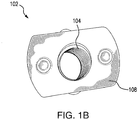
- FIGURES 1A and 1B illustrate an example nutplate 102 and surface 112, according to a particular embodiment.
- nutplate 102 is joined to surface 112 such that one or more bolts, screws, rivets, or other fasteners can pass through both surface 112 and nutplate 102, attach to nut 104 of nutplate 102, and thus attach, secure, or otherwise affix surface 112 in place or to another surface or component.
- nutplate 102 contains nut 104 and plate 106, where plate 106 has a faying surface 108.
- nutplate 102 has a worm 110 passing through nut 104 and plate 106.
- Nutplate 102 is generally a component that allows a nut, e.g., nut 104, to be positioned on or in close proximity to a surface, e.g. surface 112.
- Nutplate 102 in certain embodiments, contains plate 106 and nut 104, where nutplate 102 attaches to a surface, e.g., surface 112, via a connection between plate 106 and surface 112 at faying surface 108.
- an adhesive may be placed between plate 106 and surface 112 such that plate 106 (and thus nutplate 102) is bonded to surface 112.
- Any suitable nutplate of any suitable configuration is contemplated.
- nutplates having nuts that accept 6/16", 5/16", 4/16", 3/16" etc. bolts may be used. Additional examples include open style nutplates and dome nutplates.
- Nut 104 generally acts as a location for fasteners, such as bolts, screws, rivets, etc. to attach/fasten.
- a "nut” as used in this application may be any suitable location for a fastener, for example a component with a cylindrical/circular, rectilinear, or hexagonal opening that allows a fastener to at least partially pass through the opening and attach to the nut.
- nut 104 may have threads for a bolt or screw on its inside surface (this area in FIGURE 1 is filled with worm 110).
- nut 104 is attached to plate 106 via any suitable means, such as welding, press fitting, use of adhesives, etc.
- nut 104 is coupled to plate 106 in such a way that allows nut 104 to be free floating (e.g., nut 104 may rotate or tilt a limited amount to accommodate certain tolerances).
- a face or portion of nut 104 may extend through a portion of plate 106 (e.g., such that a face of nut 104 is flush with plate 106), such that the surface or portion of nut 106 is a faying surface or part of a larger faying surface (such as faying surface 108).
- Nut 104 can be made of any suitable material such as steel, aluminum, or other metals, a metal alloy, polymer, ceramic, etc.
- Plate 106 generally provides a surface to which nut 104 can attach, and a surface to which a surface (e.g., surface 112) can attach to nutplate 102.
- plate 106 may have an opening centered with (or otherwise over) an opening of nut 104 that allows a fastener to pass through plate 106 and make contact with nut 104.
- Plate 106 can be made of any suitable material such as steel, aluminum, or other metals, a metal alloy, polymer, ceramic, etc.
- Faying surface 108 is generally a surface of plate 106 that attaches to another surface, such as surface 112. Faying surface 108 may attach to surface 112 via any suitable means, such as with an adhesive, welding, press fitting, etc. In certain embodiments, faying surface 108 should be clean (e.g., have few contaminants on its surface) such that a strong bond (e.g., via use of an adhesive) can form between plate 106 and surface 112. Faying surface 108, in certain embodiments, may include some of nut 104, such as a face of nut 104 protruding through a portion of plate 106. In some embodiments, the cleaner faying surface 106, the stronger the bond between nutplate 102, via plate 106, and surface 112.
- Worm 110 generally provides the ability to manipulate nutplate 102 and keeps the inside surface(s) of nut 104 (where, e.g., a fastener fastens to nut 104) clean and free of debris or other contaminants.
- worm 110 may extend past plate 106 and pass through an opening in surface 112 such that an operator or device can grab worm 110 and pull it further through the opening of surface 112, thereby seating faying surface 108 on surface 112 and aligning the opening in surface 112, plate 106 and nut 104.
- Worm 110 may also extend below nut 104 in some embodiments.
- worm 110 can be removed from nutplate 102, thus exposing inside surfaces of nut 104 and allowing a fastener to fasten to nut 104.
- worm 110 keeps the inside surface(s) of nut 104 (e.g., threads for a bolt) clean by keeping debris, oil, and other contaminants off of the inside surface(s) of nut 104.
- Worm 110 can be made of any suitable substance, such as silicone, rubber, polymer, wax, etc.
- Surface 112 is generally any surface to which nutplate 102 can attach.
- surface 112 may have an opening that a fastener can pass through, and nutplate 102 can attach to surface 112 such that openings in plate 106 and nut 104 align with the opening in surface 112.
- the fastener may be able to pass through surface 112, plate 106, at least partially through nut 104, and fasten to nut 104.
- surface 112 may be an outer panel of an aircraft wing with an opening for a bolt, and nutplate 102 may attach to the inside of the aircraft wing such that the bolt can pass through surface 112 and be threaded into or out of the nutplate from the outside of the wing.
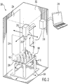
- FIGURE 2 illustrates an example laser system 200 for cleaning nutplates, according to a particular embodiment.
- laser system 200 cleans a faying surface of nutplates, such as faying surface 108, to prepare nutplates before attaching them to a surface, e.g., surface 112 of FIGURE 1 .
- laser system 200 may clean or otherwise remove contaminants from a faying surface of nutplate, which may be referred to as laser ablation, such that an adhesive can be placed on the cleaned faying surface and more readily or strongly bond to the faying surface.
- laser system 200 contains a container 202 with a door 204, where inside container 202 a nutplate tray 206 holding nutplates 102 rests on a conveyor 208, and a laser 210 having a lens 212 faces nutplates 102 at a distance 214 from nutplates 102.
- laser system 200 contains a controller 216 and a terminal 218.
- Container 202 generally contains some or all of the components of laser system 200 (also referred to as a nutplate laser cleaning system) and, in certain embodiments, protects operators of system 200 from potentially harmful exposure to laser 210.
- Container 202 can be made of any suitable material, such as metal, polymer, glass, etc. and may be opaque, transparent, semi-transparent, or any combination thereof.
- Container 202 in some embodiments has a door 204, wherein door 204 provides access to the inside of container 202 (e.g., allows for nutplates to be placed in container 202 or removed from container 202) and increases the safety of laser system 200 by protecting operators from laser 210 when door 204 is closed.
- Door 204 can be made of any suitable material, such as metal, polymer, glass, etc. and may be opaque, transparent, semi-transparent, or any combination of thereof.
- container 202 may contain or connect to a vacuum system that creates a complete or partial vacuum (or otherwise reduces the pressure) in container 202.
- a vacuum system may remove air, dust, and other matter that can settle on nutplates 102, scatter or otherwise interfere with laser 210, or chemically react with the faying surfaces during cleaning.
- Nutplate tray 206 generally holds nutplates 102 during the laser cleaning process.
- nutplate tray 206 is configured to hold nutplates of a specific shape.
- Nutplate tray 206 may be customized for particular nutplate type(s)/shape(s), or contain different customized inserts for different nutplate types/shapes, e.g., in order to hold nutplates 102 steady and such that faying surface 108 is a particular distance from laser 210 or laser lens 212.
- nutplate tray 206 may be able to hold 16 nutplates of one or more shapes or styles (e.g., open style or dome) in a four by four arrangement.
- Nutplate tray 206 may also, in some embodiments, allow for worm 110 and nut 104 of nutplate 102 to extend below nutplate tray 206.
- nutplate tray 206 is configured to hold nutplates such that the faying surfaces 108 of the nutplates 102 are facing (oriented) toward laser 210.
- nutplate tray 206 may hold faying surfaces 108 of nutplates 102 at a particular distance 214 (e.g., a focal distance of lens 212) from laser lens 212, such that, for example, laser 210 (or a laser beam generated by laser 210) is at its maximum intensity for a given output while using lens 212 (or within 1%, 2%, 5%, 10%, 25%, 50%, etc. of its maximum intensity) at the distance between laser lens 212 and faying surfaces 108.
- Nutplate trays 206 of different heights may be used to change distance 214 in certain embodiments, such as to get closer to the focal distance of lens 212.
- Nutplate tray 206 may be made out of any suitable material such as metal, polymer, etc. and may be made by any suitable means such as dynamically being created by a 3D printer in response to a new batch of nutplates arriving or being scheduled to arrive.
- nutplate tray 206 may be configured to hold nutplates 102 such that each faying surface of nutplates 102 is oriented such that a laser beam produced by laser 210 is capable of contacting each faying surface at least once during a cleaning cycle.
- a cleaning cycle may contain any number of movements of any number of components of laser system 200, such as multiple passes of laser 210 created by laser 210 moving and/or nutplate tray 206 moving (e.g., via conveyor 208) such that laser 210 cleans multiple nutplates.
- Conveyor 208 generally moves nutplate tray 206 during cleaning to help clean multiple nutplates 102.
- conveyor 208 moves nutplate tray 206 in one or more directions such that a laser beam from laser 210 makes contact with and cleans multiple (or all) faying surfaces 108 of nutplates 102 in nutplate tray 206.
- conveyor 208 translates nutplate 206 in the X and Y directions (2D) such that the distance 214 between faying surface 108 and lens 212 (e.g., a focal distance of lens 212) is constant for multiple nutplates 102, which may increase the consistency and effectiveness of cleaning nutplates 102.
- conveyor 208 may move nutplate tray 206 in the Z direction or in no direction. Conveyor 208, in some embodiments, may move nutplate tray 206 according to instructions from controller 216. While conveyor 208 moves nutplate tray 206 (or remains stationary), laser 210 may be stationary or may be moving in the X, Y, or Z direction.
- Laser 210 generally produces a laser (also described as a laser beam) directed towards nutplates 102, particularly faying surfaces 108.
- the laser beam produced by laser 210 impacts faying surface 108 in certain embodiments and removes some or all contaminants from faying surface 210.
- the process of cleaning nutplate faying surfaces 108 with a laser may be referred to as a form of laser ablation.
- laser 210 produces a laser beam that is orthogonal to faying surface 108 or any suitable angle to faying surface 108.
- Laser 210 may also make multiple passes (e.g., by laser 210 moving, nutplate tray 206 moving, or both) at the same nutplate at the same or different angles.
- FIGURE 3 describes example embodiments where multiple passes of laser 210 occur at different angles.
- laser 210 is a Nd:YAG (neodymium-doped yttrium aluminum garnet) class 1 or class 4 laser producing a laser beam with a wavelength of 1064 nm (nanometers), though any suitable laser of any type, class, or wavelength can be used to clean nutplates 102 (e.g., faying surface 108).
- a suitable laser beam may have a wavelength of between 100 nm and 7,000 nm, 500 nm and 3,000 nm, 800 nm and 2000 nm, 1000 nm and 1200 nm, 1000 nm and 1100 nm, 1050 nm and 1075 nm, or any other suitable range.
- a laser beam produced by laser 210 may be any suitable type of laser beam.
- the laser beam may be a pulse laser.
- Certain embodiments of the present disclosure contemplate using or modifying characteristics of laser beams produced by laser 210, such as mark speed (how fast the laser moves back and forth across an area), angle, intensity, beam width, pulse frequency, etc.
- controller 216 controls some or all laser characteristics, automatically or based on user input. In other embodiments, laser characteristics or laser position may be manipulated manually.
- laser 210 can move in space relative to nutplates 102 and nutplate tray 206.
- laser 210 may be able to move in the X, Y, Z, or any combination of these directions.
- laser 210 may tilt at any angle.
- the movement of laser 210 is controlled by controller 216.
- Laser 210 may move across nutplate tray 206 (which may include tilting) at one or more angles and one or more times (passes) in certain embodiments.
- Laser 210 may be pointed down at faying surfaces 108, but any orientation of laser 210 and faying surfaces 108 are contemplated, e.g., where laser 210 is pointed in the Y direction toward a nutplate tray that is mounted on the X-Z plane of FIGURE 2 . All other components of laser system 200 may be moved in relation to one another to accommodate any suitable setup.
- Lens 212 generally focuses a laser beam emitted from laser 210.
- lens 212 has a focal distance, such that at the focal distance away from lens 212 a laser beam generated by laser 210 passing through the lens will have maximum intensity (energy per unit area) for any given power output from laser 210.
- a faying surface 108 that is a focal distance away from lens 212 (where distance 214 equals a focal distance of lens 212) will therefore encounter a laser beam produced by laser 210 at its maximum intensity in certain embodiments.
- distance 214 may be at such a focal distance or within 1%, 2%, 5%, 10%, 25%, 50%, etc. of the focal distance.
- Lens 212 is connected to laser 210 in certain embodiments, for example by threading onto laser 210. Different lenses may have different focal distances. In one example, a 330 mm lens may be used, though any suitable lens of any suitable size (e.g., between 100 mm and 1000 mm, 200 mm and 500 mm, 300 mm and 400 mm, etc.) may be used.
- Distance 214 is generally the distance between lens 212 and a faying surface 108 that is in contact with a laser beam produced by laser 210. Put another way, distance 214 is generally the distance between (1) a point where a laser beam from laser 210 contacts a surface (e.g., faying surface 108) and (2) lens 212. In particular embodiments, distance 214 is selected to provide sufficient or optimal cleaning of a faying surface 108. In certain embodiments, distance 214 may be equal to the focal distance of lens 212, and at such a distance 214 a laser beam passing through lens 212 is at its maximum intensity. Distance 214 may be any suitable distance, for example within 1%, 2%, 5%, 10%, 25%, 50%, etc. of the focal distance of lens 212. Distance 214 may change over time, and the placement of laser 210 and nutplate tray 206, the height of nutplate tray 206, and the position of conveyor 208 may affect distance 214.
- Controller 216 generally controls some or all of the components of laser system 200.
- controller 216 may control the position (including the angle) of laser 210, the position of conveyor 208 (and nutplate tray 206), the speed of laser 210 and/or conveyor 208, the pattern of movement of laser 210 and/or conveyor 208, characteristics of laser beams produced by laser 210, or any other component of laser system 200.
- Controller 216 may contain a processor and/or memory of any suitable type, including any kind of non-transient computer readable medium. Such processor and memory resources may be located locally within controller 216, within other components of laser system 200, or external to laser system 200 as a network resource (e.g., a private network, public network, or cloud computing resource).
- Controller 216 may also contain software (e.g., a program) for controlling components of laser system 200. Such software may be installed, modified, operated, or interacted with via terminal 218 or via a network.
- Terminal 218 generally acts as an input/output device for controller 216.
- terminal 218 may contain a display screen and a keyboard that allows a user to see the status of laser system 200 and enter commands to laser system 200.
- terminal 218 can be used to control or operate controller 216.
- Terminal 218, in particular embodiments, may be a computer, such as a laptop, desktop, tablet, server, PDA, smartphone, or any other suitable device.
- terminal 218 may contain some or all of the processor and memory resources used by controller 216.
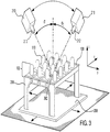
- FIGURE 3 illustrates an example of certain components of laser system 200 of FIGURE 2 while conducting multiple passes to clean nutplates 102, according to a particular embodiment. More specifically, FIGURE 3 illustrates laser 210 conducting two passes across a nutplate at angles ⁇ 1 and ⁇ 2.
- Nutplates 102 are shown in this example embodiment as being held by nutplate tray 206 resting on conveyor 208. Nutplates 102 have faying surfaces 108 that are in the process of being cleaned by laser 210 having lens 212.
- laser 210 is shown making two passes, the first at a first position having angle ⁇ 1 and the second at a second position having angle ⁇ 2.
- a single pass at any position having any angle could produce a shadow effect, where, e.g., worm 110 comes between a laser beam produced by laser 210 and faying surface 108, which produces an area that is not cleaned by laser 210 (a shadow area 302).
- laser 210 can make multiple passes over faying surface 108 at different positions (e.g. at ⁇ 1 and ⁇ 2), such that more or all of faying surface 108 is cleaned at least once by laser 210 than if just one pass were completed.
- Such multiple passes at different positions, e.g., having different angles may reduce or eliminate the shadow effect and shadow area 302.
- Angles ⁇ 1 and ⁇ 2 may describe angles measures relative to any suitable axis, such as the X, Y, or Z axes as shown in FIGURE 3 , and in any suitable plane.
- ⁇ 1 and ⁇ 2 are measured from the Z axis (orthogonal to faying surfaces 108 and located where the laser beam meets the faying surface) along the Z-Y plane.
- Angles ⁇ 1 and ⁇ 2 may be any suitable angle, including 0°, and may change over time during a particular pass of between particular passes.
- the laser system of FIGURE 2 may conduct a cleaning cycle, e.g., containing one or more passes of laser 210 across faying surfaces 108 of nutplates 102 held by nutplate tray 206.
- nutplate tray 206 holds nutplates 102 such that a faying surface of each nutplate 102 is accessible by a laser beam produced by laser 210 for cleaning at least once during the cleaning cycle, whether on the same pass of laser 210 or one different passes of laser 210 during the cleaning cycle.
- FIGURE 3 describes particular embodiments, any number of passes of laser 210 (or multiple lasers) having any position, including any angle, are contemplated.
- laser system 200 may be used to clean faying surfaces of any other appropriate part (e.g., small parts with surfaces that are typically abrasively cleaned).
- some embodiments of laser system 200 may be used to clean parts such as radius blocks, shims, click bond studs, brackets, and the like.
- tray 206 may be customized for the shape of the particular parts in order to hold the parts steady during cleaning and such that faying surfaces of the parts are a particular distance from laser 210 or laser lens 212.
- each refers to each member of a set or each member of a subset of a set.
- or is not necessarily exclusive and, unless expressly indicated otherwise, can be inclusive in certain embodiments and can be understood to mean “and/or.”
- and is not necessarily inclusive and, unless expressly indicated otherwise, can be inclusive in certain embodiments and can be understood to mean “and/or.”
- an apparatus or system or a component of an apparatus or system being adapted to, arranged to, capable of, configured to, enabled to, operable to, or operative to perform a particular function encompasses that apparatus, system, component, whether or not it or that particular function is activated, turned on, or unlocked, as long as that apparatus, system, or component is so adapted, arranged, capable, configured, enabled, operable, or operative.
Landscapes
- Engineering & Computer Science (AREA)
- Physics & Mathematics (AREA)
- Optics & Photonics (AREA)
- Mechanical Engineering (AREA)
- Plasma & Fusion (AREA)
- General Engineering & Computer Science (AREA)
- Chemical & Material Sciences (AREA)
- Composite Materials (AREA)
- Cleaning In General (AREA)
- Laser Beam Processing (AREA)
Abstract
Description
- This disclosure relates in general to nutplate preparation, and more specifically to laser systems for nutplate preparation.
- Nutplates are often used to create a binding location on a surface, such as on aircraft, boats, etc. An example nutplate contains a nut connected to a plate, where the plate attaches to a surface and the nut provides a location to accept a bolt passing through the surface (a binding location). Nutplates can sometimes be found on the inside of surfaces, such as on the inside surface of an aircraft body or boat hull, where it is difficult or impossible to place a nut after the surface is assembled or placed on the body or hull without causing damage. The plate of the nutplate is often attached to the surface, sometimes with an adhesive, and thus, the cleaner the plate of the nutplate, the more reliable or strong the bond between the plate and the surface in some instances.
- According to one embodiment, a system includes a laser configured to conduct a cleaning cycle that includes producing a laser beam capable of cleaning a faying surface of each of a plurality of nutplates, and conducting a first pass to clean each of the faying surfaces, wherein the laser is at a first position having a first angle relative to an axis orthogonal to the faying surfaces during the first pass. The system also includes a nutplate tray configured to hold the plurality of nutplates such that each faying surface is oriented such that the laser beam is capable of contacting each faying surface at least once during the cleaning cycle.
- According to another embodiment, a method includes placing a plurality of parts in a tray configured to hold the plurality of parts and orienting the tray such that a faying surface of each of the plurality of parts is oriented such that a laser beam from a laser is capable of contacting each faying surface at least once during a cleaning cycle. The method also includes conducting the cleaning cycle, which includes producing, by the laser, the laser beam capable of cleaning a faying surface of each of a plurality of parts, and conducting a first pass to clean each of the faying surfaces, wherein the laser is at a first position having a first angle relative to an axis orthogonal to the faying surfaces during the first pass.
- Technical advantages of certain embodiments may include systems and methods for obtaining cleaner nutplates and other parts, and in particular cleaner faying surfaces on nutplates and other parts. By obtaining cleaner faying surfaces, parts such as nutplates can be more securely attached to surfaces, especially when adhesives are applied to the faying surfaces. In addition, systems and methods of this disclosure may more efficiently and/or quickly clean multiple parts such as nutplates at the same time compared to other systems and methods. Furthermore, parts such as nutplates are often sent to manufactures in special expensive packaging, such as vacuum sealed aluminum pouches to avoid contamination. By using certain embodiments of this disclosure, the need to use expensive special packaging may be reduced, thus reducing the cost of nutplates.
- Other technical advantages will be readily apparent to one skilled in the art from the following figures, descriptions, and claims. Moreover, while specific advantages have been enumerated above, various embodiments may include all, some, or none of the enumerated advantages.
- For a more complete understanding of the present disclosure and its advantages, reference is now made to the following description, taken in conjunction with the accompanying drawings, in which:
-
FIGURES 1A and1B illustrate an example nutplate and surface, according to a particular embodiment; -
FIGURE 2 illustrates an example laser system for cleaning nutplates, according to a particular embodiment; and -
FIGURE 3 illustrates an example of certain components of the laser system ofFIGURE 2 while conducting multiple passes to clean nutplates, according to a particular embodiment. - In every-day life, nutplates are often used to create a binding location on a surface, such as on aircraft, boats, etc. An example nutplate contains a nut connected to a plate, where the plate attaches to a surface and the nut provides a location to accept a bolt passing through the surface (a binding location). Nutplates can sometimes be found on the inside of surfaces, such as on the inside surface of an aircraft body or boat hull, where it is difficult or impossible to place a nut after the surface is assembled or placed on the body or hull. The plate of the nutplate is often attached to the surface, sometimes with an adhesive, and thus, the cleaner the plate of the nutplate, the more reliable or strong the bond between the plate and the surface in some instances.
- Certain embodiments of the present disclosure describe systems and methods of cleaning nutplate surfaces, such as nutplate faying surfaces. A faying surface on a nutplate is generally a surface that forms part of a joint or attachment to another surface. For example, adhesives are sometimes placed on a faying surface of a nutplate, and then the faying surface is pressed against a surface to which the nutplate will be bound.
- Laser cleaning, which may be partially or fully automated according to certain embodiments of this disclosure, may help clean faying surfaces more thoroughly than other techniques, such as types of grit blasting or sanding. For example, nutplates may be placed in a nutplate tray such that the faying surfaces of the nutplates are oriented towards a laser. The laser may then shoot a laser beam at the array of nutplates in the tray while moving relative to the nutplate tray in a pattern during one or more passes. When the laser contacts the faying surfaces of the nutplates, it cleans (e.g., removes contaminants from) the faying surfaces.
- Technical advantages of certain embodiments may include systems and methods for obtaining cleaner nutplates, and in particular cleaner faying surfaces on nutplates. By obtaining cleaner faying surfaces, nutplates can be more securely attached to surfaces, especially when adhesives are applied to the faying surfaces. In addition, systems and methods of this disclosure may more efficiently and/or quickly clean multiple nutplates at the same time compared to other systems and methods. Furthermore, certain embodiments of this disclosure may reduce the need to use expensive special packaging for nutplates, thus reducing the cost of nutplates. Other technical advantages will be readily apparent to one skilled in the art from the following figures, descriptions, and claims. Moreover, while specific advantages have been enumerated above, various embodiments may include all, some, or none of the enumerated advantages.
-
FIGURES 1A and1B illustrate anexample nutplate 102 andsurface 112, according to a particular embodiment. In some embodiments,nutplate 102 is joined tosurface 112 such that one or more bolts, screws, rivets, or other fasteners can pass through bothsurface 112 andnutplate 102, attach tonut 104 ofnutplate 102, and thus attach, secure, or otherwise affixsurface 112 in place or to another surface or component. In particular embodiments,nutplate 102 containsnut 104 andplate 106, whereplate 106 has afaying surface 108. In addition, in some embodiments,nutplate 102 has aworm 110 passing throughnut 104 andplate 106. -
Nutplate 102 is generally a component that allows a nut, e.g.,nut 104, to be positioned on or in close proximity to a surface,e.g. surface 112.Nutplate 102, in certain embodiments, containsplate 106 andnut 104, wherenutplate 102 attaches to a surface, e.g.,surface 112, via a connection betweenplate 106 andsurface 112 atfaying surface 108. For example, an adhesive may be placed betweenplate 106 andsurface 112 such that plate 106 (and thus nutplate 102) is bonded tosurface 112. Any suitable nutplate of any suitable configuration is contemplated. As examples, nutplates having nuts that accept 6/16", 5/16", 4/16", 3/16" etc. bolts may be used. Additional examples include open style nutplates and dome nutplates. -
Nut 104 generally acts as a location for fasteners, such as bolts, screws, rivets, etc. to attach/fasten. A "nut" as used in this application may be any suitable location for a fastener, for example a component with a cylindrical/circular, rectilinear, or hexagonal opening that allows a fastener to at least partially pass through the opening and attach to the nut. For example,nut 104 may have threads for a bolt or screw on its inside surface (this area inFIGURE 1 is filled with worm 110). In anexample nutplate 102,nut 104 is attached toplate 106 via any suitable means, such as welding, press fitting, use of adhesives, etc. In some embodiments,nut 104 is coupled toplate 106 in such a way that allowsnut 104 to be free floating (e.g.,nut 104 may rotate or tilt a limited amount to accommodate certain tolerances). In certain embodiments, a face or portion ofnut 104 may extend through a portion of plate 106 (e.g., such that a face ofnut 104 is flush with plate 106), such that the surface or portion ofnut 106 is a faying surface or part of a larger faying surface (such as faying surface 108).Nut 104 can be made of any suitable material such as steel, aluminum, or other metals, a metal alloy, polymer, ceramic, etc. -
Plate 106 generally provides a surface to whichnut 104 can attach, and a surface to which a surface (e.g., surface 112) can attach tonutplate 102. In example embodiments,plate 106 may have an opening centered with (or otherwise over) an opening ofnut 104 that allows a fastener to pass throughplate 106 and make contact withnut 104.Plate 106 can be made of any suitable material such as steel, aluminum, or other metals, a metal alloy, polymer, ceramic, etc. -
Faying surface 108 is generally a surface ofplate 106 that attaches to another surface, such assurface 112.Faying surface 108 may attach tosurface 112 via any suitable means, such as with an adhesive, welding, press fitting, etc. In certain embodiments,faying surface 108 should be clean (e.g., have few contaminants on its surface) such that a strong bond (e.g., via use of an adhesive) can form betweenplate 106 andsurface 112.Faying surface 108, in certain embodiments, may include some ofnut 104, such as a face ofnut 104 protruding through a portion ofplate 106. In some embodiments, thecleaner faying surface 106, the stronger the bond betweennutplate 102, viaplate 106, andsurface 112. -
Worm 110 generally provides the ability to manipulatenutplate 102 and keeps the inside surface(s) of nut 104 (where, e.g., a fastener fastens to nut 104) clean and free of debris or other contaminants. For example,worm 110 may extendpast plate 106 and pass through an opening insurface 112 such that an operator or device can grabworm 110 and pull it further through the opening ofsurface 112, thereby seatingfaying surface 108 onsurface 112 and aligning the opening insurface 112,plate 106 andnut 104.Worm 110 may also extend belownut 104 in some embodiments. In certain embodiments, oncenutplate 102 is attached to surface 112,worm 110 can be removed fromnutplate 102, thus exposing inside surfaces ofnut 104 and allowing a fastener to fasten tonut 104. In addition, in some embodiments,worm 110 keeps the inside surface(s) of nut 104 (e.g., threads for a bolt) clean by keeping debris, oil, and other contaminants off of the inside surface(s) ofnut 104.Worm 110 can be made of any suitable substance, such as silicone, rubber, polymer, wax, etc. -
Surface 112 is generally any surface to which nutplate 102 can attach. In certain embodiments,surface 112 may have an opening that a fastener can pass through, andnutplate 102 can attach to surface 112 such that openings inplate 106 andnut 104 align with the opening insurface 112. In such embodiments, the fastener may be able to pass throughsurface 112,plate 106, at least partially throughnut 104, and fasten tonut 104. In an example embodiment,surface 112 may be an outer panel of an aircraft wing with an opening for a bolt, andnutplate 102 may attach to the inside of the aircraft wing such that the bolt can pass throughsurface 112 and be threaded into or out of the nutplate from the outside of the wing. -
FIGURE 2 illustrates anexample laser system 200 for cleaning nutplates, according to a particular embodiment. In general,laser system 200 cleans a faying surface of nutplates, such asfaying surface 108, to prepare nutplates before attaching them to a surface, e.g.,surface 112 ofFIGURE 1 . For example,laser system 200 may clean or otherwise remove contaminants from a faying surface of nutplate, which may be referred to as laser ablation, such that an adhesive can be placed on the cleaned faying surface and more readily or strongly bond to the faying surface. In certain embodiments,laser system 200 contains acontainer 202 with adoor 204, where inside container 202 anutplate tray 206 holdingnutplates 102 rests on aconveyor 208, and alaser 210 having alens 212 facesnutplates 102 at adistance 214 fromnutplates 102. In addition,laser system 200 contains acontroller 216 and a terminal 218. -
Container 202 generally contains some or all of the components of laser system 200 (also referred to as a nutplate laser cleaning system) and, in certain embodiments, protects operators ofsystem 200 from potentially harmful exposure tolaser 210.Container 202 can be made of any suitable material, such as metal, polymer, glass, etc. and may be opaque, transparent, semi-transparent, or any combination thereof. -
Container 202 in some embodiments has adoor 204, whereindoor 204 provides access to the inside of container 202 (e.g., allows for nutplates to be placed incontainer 202 or removed from container 202) and increases the safety oflaser system 200 by protecting operators fromlaser 210 whendoor 204 is closed.Door 204 can be made of any suitable material, such as metal, polymer, glass, etc. and may be opaque, transparent, semi-transparent, or any combination of thereof. - In certain embodiments,
container 202 may contain or connect to a vacuum system that creates a complete or partial vacuum (or otherwise reduces the pressure) incontainer 202. Such a vacuum system may remove air, dust, and other matter that can settle onnutplates 102, scatter or otherwise interfere withlaser 210, or chemically react with the faying surfaces during cleaning. -
Nutplate tray 206 generally holdsnutplates 102 during the laser cleaning process. In certain embodiments,nutplate tray 206 is configured to hold nutplates of a specific shape.Nutplate tray 206 may be customized for particular nutplate type(s)/shape(s), or contain different customized inserts for different nutplate types/shapes, e.g., in order to holdnutplates 102 steady and such thatfaying surface 108 is a particular distance fromlaser 210 orlaser lens 212. For example,nutplate tray 206 may be able to hold 16 nutplates of one or more shapes or styles (e.g., open style or dome) in a four by four arrangement.Nutplate tray 206 may also, in some embodiments, allow forworm 110 andnut 104 ofnutplate 102 to extend belownutplate tray 206. In certain embodiments,nutplate tray 206 is configured to hold nutplates such that the faying surfaces 108 of thenutplates 102 are facing (oriented) towardlaser 210. Furthermore,nutplate tray 206, in some embodiments, may holdfaying surfaces 108 ofnutplates 102 at a particular distance 214 (e.g., a focal distance of lens 212) fromlaser lens 212, such that, for example, laser 210 (or a laser beam generated by laser 210) is at its maximum intensity for a given output while using lens 212 (or within 1%, 2%, 5%, 10%, 25%, 50%, etc. of its maximum intensity) at the distance betweenlaser lens 212 and faying surfaces 108.Nutplate trays 206 of different heights may be used to changedistance 214 in certain embodiments, such as to get closer to the focal distance oflens 212.Nutplate tray 206 may be made out of any suitable material such as metal, polymer, etc. and may be made by any suitable means such as dynamically being created by a 3D printer in response to a new batch of nutplates arriving or being scheduled to arrive. - In certain embodiments,
nutplate tray 206 may be configured to holdnutplates 102 such that each faying surface ofnutplates 102 is oriented such that a laser beam produced bylaser 210 is capable of contacting each faying surface at least once during a cleaning cycle. A cleaning cycle may contain any number of movements of any number of components oflaser system 200, such as multiple passes oflaser 210 created bylaser 210 moving and/ornutplate tray 206 moving (e.g., via conveyor 208) such thatlaser 210 cleans multiple nutplates. -
Conveyor 208 generally movesnutplate tray 206 during cleaning to help cleanmultiple nutplates 102. For example, in some embodiments,conveyor 208 movesnutplate tray 206 in one or more directions such that a laser beam fromlaser 210 makes contact with and cleans multiple (or all)faying surfaces 108 ofnutplates 102 innutplate tray 206. In certain embodiments,conveyor 208 translatesnutplate 206 in the X and Y directions (2D) such that thedistance 214 betweenfaying surface 108 and lens 212 (e.g., a focal distance of lens 212) is constant formultiple nutplates 102, which may increase the consistency and effectiveness of cleaningnutplates 102. In some embodiments,conveyor 208 may movenutplate tray 206 in the Z direction or in no direction.Conveyor 208, in some embodiments, may movenutplate tray 206 according to instructions fromcontroller 216. Whileconveyor 208 moves nutplate tray 206 (or remains stationary),laser 210 may be stationary or may be moving in the X, Y, or Z direction. -
Laser 210 generally produces a laser (also described as a laser beam) directed towardsnutplates 102, particularly faying surfaces 108. The laser beam produced bylaser 210impacts faying surface 108 in certain embodiments and removes some or all contaminants fromfaying surface 210. The process of cleaning nutplate fayingsurfaces 108 with a laser may be referred to as a form of laser ablation. In certain embodiments,laser 210 produces a laser beam that is orthogonal to fayingsurface 108 or any suitable angle tofaying surface 108.Laser 210 may also make multiple passes (e.g., bylaser 210 moving,nutplate tray 206 moving, or both) at the same nutplate at the same or different angles.FIGURE 3 describes example embodiments where multiple passes oflaser 210 occur at different angles. - In an example embodiment,
laser 210 is a Nd:YAG (neodymium-doped yttrium aluminum garnet) class 1 or class 4 laser producing a laser beam with a wavelength of 1064 nm (nanometers), though any suitable laser of any type, class, or wavelength can be used to clean nutplates 102 (e.g., faying surface 108). For example, a suitable laser beam may have a wavelength of between 100 nm and 7,000 nm, 500 nm and 3,000 nm, 800 nm and 2000 nm, 1000 nm and 1200 nm, 1000 nm and 1100 nm, 1050 nm and 1075 nm, or any other suitable range. - A laser beam produced by
laser 210 may be any suitable type of laser beam. For example, the laser beam may be a pulse laser. Certain embodiments of the present disclosure contemplate using or modifying characteristics of laser beams produced bylaser 210, such as mark speed (how fast the laser moves back and forth across an area), angle, intensity, beam width, pulse frequency, etc. In certain embodiments,controller 216 controls some or all laser characteristics, automatically or based on user input. In other embodiments, laser characteristics or laser position may be manipulated manually. - In some embodiments,
laser 210 can move in space relative to nutplates 102 andnutplate tray 206. For example,laser 210 may be able to move in the X, Y, Z, or any combination of these directions. In addition,laser 210 may tilt at any angle. In certain embodiments, the movement oflaser 210 is controlled bycontroller 216.Laser 210 may move across nutplate tray 206 (which may include tilting) at one or more angles and one or more times (passes) in certain embodiments.Laser 210 may be pointed down atfaying surfaces 108, but any orientation oflaser 210 andfaying surfaces 108 are contemplated, e.g., wherelaser 210 is pointed in the Y direction toward a nutplate tray that is mounted on the X-Z plane ofFIGURE 2 . All other components oflaser system 200 may be moved in relation to one another to accommodate any suitable setup. -
Lens 212 generally focuses a laser beam emitted fromlaser 210. In certain embodiments,lens 212 has a focal distance, such that at the focal distance away from lens 212 a laser beam generated bylaser 210 passing through the lens will have maximum intensity (energy per unit area) for any given power output fromlaser 210. Afaying surface 108 that is a focal distance away from lens 212 (wheredistance 214 equals a focal distance of lens 212) will therefore encounter a laser beam produced bylaser 210 at its maximum intensity in certain embodiments. In some embodiments,distance 214 may be at such a focal distance or within 1%, 2%, 5%, 10%, 25%, 50%, etc. of the focal distance.Lens 212 is connected tolaser 210 in certain embodiments, for example by threading ontolaser 210. Different lenses may have different focal distances. In one example, a 330 mm lens may be used, though any suitable lens of any suitable size (e.g., between 100 mm and 1000 mm, 200 mm and 500 mm, 300 mm and 400 mm, etc.) may be used. -
Distance 214 is generally the distance betweenlens 212 and afaying surface 108 that is in contact with a laser beam produced bylaser 210. Put another way,distance 214 is generally the distance between (1) a point where a laser beam fromlaser 210 contacts a surface (e.g., faying surface 108) and (2)lens 212. In particular embodiments,distance 214 is selected to provide sufficient or optimal cleaning of afaying surface 108. In certain embodiments,distance 214 may be equal to the focal distance oflens 212, and at such a distance 214 a laser beam passing throughlens 212 is at its maximum intensity.Distance 214 may be any suitable distance, for example within 1%, 2%, 5%, 10%, 25%, 50%, etc. of the focal distance oflens 212.Distance 214 may change over time, and the placement oflaser 210 andnutplate tray 206, the height ofnutplate tray 206, and the position ofconveyor 208 may affectdistance 214. -
Controller 216 generally controls some or all of the components oflaser system 200. For example,controller 216 may control the position (including the angle) oflaser 210, the position of conveyor 208 (and nutplate tray 206), the speed oflaser 210 and/orconveyor 208, the pattern of movement oflaser 210 and/orconveyor 208, characteristics of laser beams produced bylaser 210, or any other component oflaser system 200.Controller 216 may contain a processor and/or memory of any suitable type, including any kind of non-transient computer readable medium. Such processor and memory resources may be located locally withincontroller 216, within other components oflaser system 200, or external tolaser system 200 as a network resource (e.g., a private network, public network, or cloud computing resource).Controller 216 may also contain software (e.g., a program) for controlling components oflaser system 200. Such software may be installed, modified, operated, or interacted with viaterminal 218 or via a network. -
Terminal 218 generally acts as an input/output device forcontroller 216. For example, terminal 218 may contain a display screen and a keyboard that allows a user to see the status oflaser system 200 and enter commands tolaser system 200. In certain embodiments, terminal 218 can be used to control or operatecontroller 216.Terminal 218, in particular embodiments, may be a computer, such as a laptop, desktop, tablet, server, PDA, smartphone, or any other suitable device. In certain embodiments, terminal 218 may contain some or all of the processor and memory resources used bycontroller 216. -
FIGURE 3 illustrates an example of certain components oflaser system 200 ofFIGURE 2 while conducting multiple passes to cleannutplates 102, according to a particular embodiment. More specifically,FIGURE 3 illustrateslaser 210 conducting two passes across a nutplate at angles θ1 and θ2. -
Nutplates 102 are shown in this example embodiment as being held bynutplate tray 206 resting onconveyor 208.Nutplates 102 have fayingsurfaces 108 that are in the process of being cleaned bylaser 210 havinglens 212. - In this example,
laser 210 is shown making two passes, the first at a first position having angle θ1 and the second at a second position having angle θ2. Generally, a single pass at any position having any angle (including 0°) could produce a shadow effect, where, e.g.,worm 110 comes between a laser beam produced bylaser 210 andfaying surface 108, which produces an area that is not cleaned by laser 210 (a shadow area 302). To reduce or eliminate this shadow effect,laser 210 can make multiple passes overfaying surface 108 at different positions (e.g. at θ1 and θ2), such that more or all offaying surface 108 is cleaned at least once bylaser 210 than if just one pass were completed. Such multiple passes at different positions, e.g., having different angles may reduce or eliminate the shadow effect andshadow area 302. - Angles θ1 and θ2 may describe angles measures relative to any suitable axis, such as the X, Y, or Z axes as shown in
FIGURE 3 , and in any suitable plane. For example, in the illustrated embodiment ofFIGURE 3 , θ1 and θ2 are measured from the Z axis (orthogonal to fayingsurfaces 108 and located where the laser beam meets the faying surface) along the Z-Y plane. Angles θ1 and θ2 may be any suitable angle, including 0°, and may change over time during a particular pass of between particular passes. In certain embodiments, the laser system ofFIGURE 2 may conduct a cleaning cycle, e.g., containing one or more passes oflaser 210 acrossfaying surfaces 108 ofnutplates 102 held bynutplate tray 206. In some embodiments,nutplate tray 206 holdsnutplates 102 such that a faying surface of each nutplate 102 is accessible by a laser beam produced bylaser 210 for cleaning at least once during the cleaning cycle, whether on the same pass oflaser 210 or one different passes oflaser 210 during the cleaning cycle. - While
FIGURE 3 describes particular embodiments, any number of passes of laser 210 (or multiple lasers) having any position, including any angle, are contemplated. - While particular embodiments of
laser system 200 have been described in reference to cleaningfaying surfaces 108 ofnutplates 102, other embodiments oflaser system 200 may be used to clean faying surfaces of any other appropriate part (e.g., small parts with surfaces that are typically abrasively cleaned). For example, some embodiments oflaser system 200 may be used to clean parts such as radius blocks, shims, click bond studs, brackets, and the like. In such embodiments,tray 206 may be customized for the shape of the particular parts in order to hold the parts steady during cleaning and such that faying surfaces of the parts are a particular distance fromlaser 210 orlaser lens 212. - As used in this document, "each" refers to each member of a set or each member of a subset of a set. Furthermore, as used in the document "or" is not necessarily exclusive and, unless expressly indicated otherwise, can be inclusive in certain embodiments and can be understood to mean "and/or." Similarly, as used in this document "and" is not necessarily inclusive and, unless expressly indicated otherwise, can be inclusive in certain embodiments and can be understood to mean "and/or."
- The scope of this disclosure encompasses all changes, substitutions, variations, alterations, and modifications to the example embodiments described or illustrated herein that a person having ordinary skill in the art would comprehend. The scope of this disclosure is not limited to the example embodiments described or illustrated herein. Moreover, although this disclosure describes and illustrates respective embodiments herein as including particular components, elements, functions, operations, or steps, any of these embodiments may include any combination or permutation of any of the components, elements, functions, operations, or steps described or illustrated anywhere herein that a person having ordinary skill in the art would comprehend. Furthermore, reference in the appended claims to an apparatus or system or a component of an apparatus or system being adapted to, arranged to, capable of, configured to, enabled to, operable to, or operative to perform a particular function encompasses that apparatus, system, component, whether or not it or that particular function is activated, turned on, or unlocked, as long as that apparatus, system, or component is so adapted, arranged, capable, configured, enabled, operable, or operative.
Claims (10)
- A system, comprising:a laser configured to conduct a cleaning cycle comprising:producing a laser beam capable of cleaning a faying surface of each of a plurality of nutplates; andconducting a first pass to clean each of the faying surfaces, wherein the laser is at a first position having a first angle relative to an axis orthogonal to the faying surfaces during the first pass; anda nutplate tray configured to hold the plurality of nutplates such that each faying surface is oriented such that the laser beam is capable of contacting each faying surface at least once during the cleaning cycle.
- A method, comprising:placing a plurality of parts in a tray configured to hold the plurality of parts;orienting the tray such that a faying surface of each of the plurality of parts is oriented such that a laser beam from a laser is capable of contacting each faying surface at least once during a cleaning cycle; andconducting the cleaning cycle, comprising:producing, by the laser, the laser beam capable of cleaning a faying surface of each of a plurality of nutplates; andconducting a first pass to clean each of the faying surfaces, wherein the laser is at a first position having a first angle relative to an axis orthogonal to the faying surfaces during the first pass.
- One or more non-transitory computer-readable media comprising logic, the logic when executed by one or more processors operable to perform operations comprising:orienting a nutplate tray, configured to hold a plurality of nutplates, such that a faying surface of each of the plurality of nutplates is oriented such that a laser beam from a laser is capable of contacting each faying surface at least once during a cleaning cycle; andconducting the cleaning cycle, comprising:producing, by the laser, the laser beam capable of cleaning a faying surface of each of a plurality of nutplates; andconducting a first pass to clean each of the faying surfaces, wherein the laser is at a first position having a first angle relative to an axis orthogonal to the faying surfaces during the first pass.
- The system of claim 1, wherein the cleaning cycle further comprises conducting a second pass to clean each of the faying surfaces, wherein the laser is at a second position having a second angle relative to an axis orthogonal to the faying surfaces during the second pass; and
wherein the first angle is different from the second angle; or
the method of claim 2 or the one or more computer-readable media of claim 3, wherein conducting the cleaning cycle further comprises conducting a second pass to clean each of the faying surfaces, wherein the laser is at a second position having a second angle relative to an axis orthogonal to the faying surfaces during the second pass; and
wherein the first angle is different from the second angle. - The system of claim 1 or of claim 4, wherein the laser is configured to move during the first pass; or
the method of claim 2 or of claim 4, further comprising moving the laser during the first pass; or
the one or more computer-readable media of claim 3 or of claim 4, wherein the computer-readable media is further operable when executed to perform operations comprising moving the laser during the first pass. - The system of claim 1 or of claim 4 or of claim 5, further comprising a conveyor, wherein the conveyor is configured to:make contact with the nutplate tray; andmove the nutplate tray during the first pass; orthe method of claim 2 or of claim 4 or of claim 5, further comprising moving, by a conveyor, the tray during the first pass; or
the one or more computer-readable media of claim 3 or of claim 4 or of claim 5, wherein the computer-readable media is further operable when executed to perform operations comprising moving, by a conveyor, the nutplate tray during the first pass. - The system of claim 1 or of claim 4 or of claim 5 or of claim 6, further comprising:a lens attached to the laser such that the laser beam passes through the lens, wherein the lens has a focal distance; andwherein a distance between the lens and a point where the laser beam contacts one of the faying surfaces is within 10 percent of the focal distance; orthe method of claim 2 or of claim 4 or of claim 5 or of claim 6, wherein:a lens is attached to the laser such that the laser beam passes through the lens, wherein the lens has a focal distance; andwherein a distance between the lens and a point where the laser beam contacts one of the faying surfaces is within 10 percent of the focal distance; orthe computer-readable medium of claim 3 or of claim 4 or of claim 5 or of claim 6, wherein:a lens is attached to the laser such that the laser beam passes through the lens, wherein the lens has a focal distance; anda distance between the lens and a point where the laser beam contacts one of the faying surfaces is within 10 percent of the focal distance.
- The system of claim 1 or of any of claim 4 to 7, further comprising a container having one or more sides, wherein the container is configured to contain the laser and the nutplate tray.
- The system of claim 1 or of any of claims 4 to 8, or the method of claim 2 or of any of claims 4 to 7, or the one or more computer-readable media of claim 3 or of any of claims 4 to 7, wherein the laser is configured to produce a laser beam having a wavelength of between 800 nm and 2000 nm.
- The method of claim 2 or of any preceding method claim, wherein the plurality of parts comprises:a plurality of radius blocks;a plurality of shims;a plurality of click bond studs; ora plurality of brackets.
Applications Claiming Priority (1)
| Application Number | Priority Date | Filing Date | Title |
|---|---|---|---|
| US15/631,001 US10737303B2 (en) | 2017-06-23 | 2017-06-23 | Nutplate preparation laser system |
Publications (2)
| Publication Number | Publication Date |
|---|---|
| EP3417953A1 true EP3417953A1 (en) | 2018-12-26 |
| EP3417953B1 EP3417953B1 (en) | 2023-11-01 |
Family
ID=62165392
Family Applications (1)
| Application Number | Title | Priority Date | Filing Date |
|---|---|---|---|
| EP18171999.8A Active EP3417953B1 (en) | 2017-06-23 | 2018-05-14 | Nutplate preparation laser system |
Country Status (3)
| Country | Link |
|---|---|
| US (2) | US10737303B2 (en) |
| EP (1) | EP3417953B1 (en) |
| JP (1) | JP6938430B2 (en) |
Families Citing this family (3)
| Publication number | Priority date | Publication date | Assignee | Title |
|---|---|---|---|---|
| US11173526B2 (en) | 2019-11-27 | 2021-11-16 | Lockheed Martin Corporation | Automated structural laser cleaning system |
| GB2592416B (en) * | 2020-02-27 | 2022-08-03 | Douwe Egberts Bv | Improvements in or relating to capsule filling lines |
| US20240367204A1 (en) * | 2023-05-03 | 2024-11-07 | Lockheed Martin Corporation | Automated Pre-Weld Tube Cleaning Using Laser Ablation |
Citations (3)
| Publication number | Priority date | Publication date | Assignee | Title |
|---|---|---|---|---|
| FR2727780A1 (en) * | 1994-12-01 | 1996-06-07 | Solaic Sa | Laser surface treatment of electronic modules support band |
| EP1297906A1 (en) * | 2001-09-28 | 2003-04-02 | Hutchinson | Method of manufacturing an anti vibration device for vehicle comprising a metal insert adhered with an elastomer |
| US20150189891A1 (en) * | 2012-08-03 | 2015-07-09 | Haas Food Equipment Gmbh | Method and apparatus for cleaning baking surfaces |
Family Cites Families (21)
| Publication number | Priority date | Publication date | Assignee | Title |
|---|---|---|---|---|
| JPS5935892A (en) | 1982-08-20 | 1984-02-27 | Nec Corp | Laser working device |
| US4861407A (en) | 1985-06-18 | 1989-08-29 | The Dow Chemical Company | Method for adhesive bonding articles via pretreatment with energy beams |
| KR900003822B1 (en) | 1985-06-18 | 1990-05-31 | 더 다우 케미칼 캄파니 | Method for producing enhanced bonds between surfaces and articles produced by the method |
| US4898650A (en) | 1988-05-10 | 1990-02-06 | Amp Incorporated | Laser cleaning of metal stock |
| US5013391A (en) | 1989-06-12 | 1991-05-07 | Physical Systems, Inc. | Adhesive nutplate assembly for mounting |
| US5780806A (en) | 1995-07-25 | 1998-07-14 | Lockheed Idaho Technologies Company | Laser ablation system, and method of decontaminating surfaces |
| RU2181134C2 (en) | 1996-07-23 | 2002-04-10 | Вантико Аг | Treatment of metal surface |
| US6573702B2 (en) * | 1997-09-12 | 2003-06-03 | New Wave Research | Method and apparatus for cleaning electronic test contacts |
| SG84519A1 (en) * | 1998-12-07 | 2001-11-20 | Advanced Systems Automation | Method and apparatus for removal of mold flash |
| JP2002045812A (en) * | 2000-07-31 | 2002-02-12 | Sharp Corp | Cleaning device and cleaning method |
| US6750421B2 (en) * | 2002-02-19 | 2004-06-15 | Gsi Lumonics Ltd. | Method and system for laser welding |
| EP1598121A3 (en) | 2004-05-18 | 2007-02-14 | Airbus Deutschland GmbH | Laser-based stripping method |
| KR100639436B1 (en) * | 2005-08-30 | 2006-10-27 | 주식회사 나인벨 | Burn-in Socket Cleaner |
| US8536483B2 (en) | 2007-03-22 | 2013-09-17 | General Lasertronics Corporation | Methods for stripping and modifying surfaces with laser-induced ablation |
| US8740152B1 (en) | 2008-05-01 | 2014-06-03 | Textron Innovations, Inc. | Rivetless nutplates for aircraft |
| WO2013141810A1 (en) * | 2012-03-21 | 2013-09-26 | Ngee Ann Polytechnic | A laser cleaning apparatus and method |
| US10407821B2 (en) * | 2012-07-10 | 2019-09-10 | Woodrow Scientific Ltd. | Methods and apparatus for laser cleaning |
| GB2511036B (en) * | 2013-02-15 | 2015-12-16 | Rolls Royce Plc | Process and Apparatus for Cleaning a Surface |
| US9919502B2 (en) | 2014-04-23 | 2018-03-20 | Schaublin Sa | Method and apparatus for preparing a surface for bonding a material thereto |
| RU2700723C2 (en) | 2014-08-13 | 2019-09-19 | Айпиджи Фотоникс Корпорэйшн | Fibre laser system with multiple beams |
| US9764383B2 (en) | 2014-10-02 | 2017-09-19 | Continental Automotive Systems, Inc. | Laser trimming surface cleaning for adhesion to cast metals |
-
2017
- 2017-06-23 US US15/631,001 patent/US10737303B2/en active Active
-
2018
- 2018-05-14 EP EP18171999.8A patent/EP3417953B1/en active Active
- 2018-06-13 JP JP2018112727A patent/JP6938430B2/en active Active
-
2020
- 2020-08-11 US US16/990,646 patent/US20200368791A1/en not_active Abandoned
Patent Citations (3)
| Publication number | Priority date | Publication date | Assignee | Title |
|---|---|---|---|---|
| FR2727780A1 (en) * | 1994-12-01 | 1996-06-07 | Solaic Sa | Laser surface treatment of electronic modules support band |
| EP1297906A1 (en) * | 2001-09-28 | 2003-04-02 | Hutchinson | Method of manufacturing an anti vibration device for vehicle comprising a metal insert adhered with an elastomer |
| US20150189891A1 (en) * | 2012-08-03 | 2015-07-09 | Haas Food Equipment Gmbh | Method and apparatus for cleaning baking surfaces |
Also Published As
| Publication number | Publication date |
|---|---|
| US20180369879A1 (en) | 2018-12-27 |
| JP2019005743A (en) | 2019-01-17 |
| JP6938430B2 (en) | 2021-09-22 |
| US10737303B2 (en) | 2020-08-11 |
| US20200368791A1 (en) | 2020-11-26 |
| EP3417953B1 (en) | 2023-11-01 |
Similar Documents
| Publication | Publication Date | Title |
|---|---|---|
| US20200368791A1 (en) | Nutplate Preparation Laser System | |
| EP3854522A1 (en) | Flexible automatic grinding device and grinding method for aircraft repairing composite material | |
| JP7573535B2 (en) | Laser processing apparatus, method of operating same, and method of using same to process a workpiece - Patents.com | |
| JP5823516B2 (en) | Electromagnet and / or vacuum crawler assembly system for moving and securing work tools on an arcuate surface such as an aircraft fuselage | |
| US8836934B1 (en) | Contamination identification system | |
| CA2797290A1 (en) | Non-destructive checking method and device for implementing the method | |
| US20160158940A1 (en) | Method and Apparatus for Multi-Stage Spar Assembly | |
| JP7325897B2 (en) | Machining device and machining method of workpiece | |
| US11129318B1 (en) | Modular system for automated portable electronic device disassembly | |
| CN103597569A (en) | Method for at least partially deconstructing a flat display screen | |
| JP2015147265A (en) | assembly apparatus | |
| KR102046011B1 (en) | Multifunctional welding jig system | |
| KR20190109240A (en) | Collar positioning system | |
| US20160067868A1 (en) | Modular end effector | |
| JP2025515436A (en) | Defect mapping and repair system and method | |
| KR101326398B1 (en) | Table for loading and fixing workpiece and glass chuck for loading and fixing workpiece | |
| CN112595368A (en) | Intelligent grinding and inspection machine | |
| CN102601740B (en) | Method of manufacturing bench for fixing and loading object to be processed | |
| JP2019005743A5 (en) | ||
| CN211247615U (en) | Laser cleaning device | |
| CN118321857A (en) | Automatic control system for disassembling waste display by utilizing automatic tool changing system | |
| KR101490322B1 (en) | Laser Champering Apparatus for Substrate | |
| CN107442947B (en) | How to Use the Split Tool and the Split Tool | |
| JP6453173B2 (en) | Apparatus and method for operating fasteners | |
| KR101925548B1 (en) | Coating layer removing apparatus |
Legal Events
| Date | Code | Title | Description |
|---|---|---|---|
| PUAI | Public reference made under article 153(3) epc to a published international application that has entered the european phase |
Free format text: ORIGINAL CODE: 0009012 |
|
| STAA | Information on the status of an ep patent application or granted ep patent |
Free format text: STATUS: THE APPLICATION HAS BEEN PUBLISHED |
|
| AK | Designated contracting states |
Kind code of ref document: A1 Designated state(s): AL AT BE BG CH CY CZ DE DK EE ES FI FR GB GR HR HU IE IS IT LI LT LU LV MC MK MT NL NO PL PT RO RS SE SI SK SM TR |
|
| AX | Request for extension of the european patent |
Extension state: BA ME |
|
| STAA | Information on the status of an ep patent application or granted ep patent |
Free format text: STATUS: REQUEST FOR EXAMINATION WAS MADE |
|
| 17P | Request for examination filed |
Effective date: 20190626 |
|
| RBV | Designated contracting states (corrected) |
Designated state(s): AL AT BE BG CH CY CZ DE DK EE ES FI FR GB GR HR HU IE IS IT LI LT LU LV MC MK MT NL NO PL PT RO RS SE SI SK SM TR |
|
| STAA | Information on the status of an ep patent application or granted ep patent |
Free format text: STATUS: EXAMINATION IS IN PROGRESS |
|
| 17Q | First examination report despatched |
Effective date: 20211220 |
|
| GRAP | Despatch of communication of intention to grant a patent |
Free format text: ORIGINAL CODE: EPIDOSNIGR1 |
|
| STAA | Information on the status of an ep patent application or granted ep patent |
Free format text: STATUS: GRANT OF PATENT IS INTENDED |
|
| INTG | Intention to grant announced |
Effective date: 20230621 |
|
| GRAS | Grant fee paid |
Free format text: ORIGINAL CODE: EPIDOSNIGR3 |
|
| GRAA | (expected) grant |
Free format text: ORIGINAL CODE: 0009210 |
|
| STAA | Information on the status of an ep patent application or granted ep patent |
Free format text: STATUS: THE PATENT HAS BEEN GRANTED |
|
| AK | Designated contracting states |
Kind code of ref document: B1 Designated state(s): AL AT BE BG CH CY CZ DE DK EE ES FI FR GB GR HR HU IE IS IT LI LT LU LV MC MK MT NL NO PL PT RO RS SE SI SK SM TR |
|
| REG | Reference to a national code |
Ref country code: GB Ref legal event code: FG4D |
|
| REG | Reference to a national code |
Ref country code: CH Ref legal event code: EP |
|
| REG | Reference to a national code |
Ref country code: DE Ref legal event code: R096 Ref document number: 602018060265 Country of ref document: DE |
|
| REG | Reference to a national code |
Ref country code: IE Ref legal event code: FG4D |
|
| P01 | Opt-out of the competence of the unified patent court (upc) registered |
Effective date: 20231101 |
|
| REG | Reference to a national code |
Ref country code: LT Ref legal event code: MG9D |
|
| REG | Reference to a national code |
Ref country code: NL Ref legal event code: MP Effective date: 20231101 |
|
| PG25 | Lapsed in a contracting state [announced via postgrant information from national office to epo] |
Ref country code: GR Free format text: LAPSE BECAUSE OF FAILURE TO SUBMIT A TRANSLATION OF THE DESCRIPTION OR TO PAY THE FEE WITHIN THE PRESCRIBED TIME-LIMIT Effective date: 20240202 |
|
| PG25 | Lapsed in a contracting state [announced via postgrant information from national office to epo] |
Ref country code: IS Free format text: LAPSE BECAUSE OF FAILURE TO SUBMIT A TRANSLATION OF THE DESCRIPTION OR TO PAY THE FEE WITHIN THE PRESCRIBED TIME-LIMIT Effective date: 20240301 |
|
| PG25 | Lapsed in a contracting state [announced via postgrant information from national office to epo] |
Ref country code: LT Free format text: LAPSE BECAUSE OF FAILURE TO SUBMIT A TRANSLATION OF THE DESCRIPTION OR TO PAY THE FEE WITHIN THE PRESCRIBED TIME-LIMIT Effective date: 20231101 |
|
| REG | Reference to a national code |
Ref country code: AT Ref legal event code: MK05 Ref document number: 1626611 Country of ref document: AT Kind code of ref document: T Effective date: 20231101 |
|
| PG25 | Lapsed in a contracting state [announced via postgrant information from national office to epo] |
Ref country code: NL Free format text: LAPSE BECAUSE OF FAILURE TO SUBMIT A TRANSLATION OF THE DESCRIPTION OR TO PAY THE FEE WITHIN THE PRESCRIBED TIME-LIMIT Effective date: 20231101 |
|
| PG25 | Lapsed in a contracting state [announced via postgrant information from national office to epo] |
Ref country code: AT Free format text: LAPSE BECAUSE OF FAILURE TO SUBMIT A TRANSLATION OF THE DESCRIPTION OR TO PAY THE FEE WITHIN THE PRESCRIBED TIME-LIMIT Effective date: 20231101 |
|
| PG25 | Lapsed in a contracting state [announced via postgrant information from national office to epo] |
Ref country code: ES Free format text: LAPSE BECAUSE OF FAILURE TO SUBMIT A TRANSLATION OF THE DESCRIPTION OR TO PAY THE FEE WITHIN THE PRESCRIBED TIME-LIMIT Effective date: 20231101 |
|
| PG25 | Lapsed in a contracting state [announced via postgrant information from national office to epo] |
Ref country code: NL Free format text: LAPSE BECAUSE OF FAILURE TO SUBMIT A TRANSLATION OF THE DESCRIPTION OR TO PAY THE FEE WITHIN THE PRESCRIBED TIME-LIMIT Effective date: 20231101 Ref country code: LT Free format text: LAPSE BECAUSE OF FAILURE TO SUBMIT A TRANSLATION OF THE DESCRIPTION OR TO PAY THE FEE WITHIN THE PRESCRIBED TIME-LIMIT Effective date: 20231101 Ref country code: IS Free format text: LAPSE BECAUSE OF FAILURE TO SUBMIT A TRANSLATION OF THE DESCRIPTION OR TO PAY THE FEE WITHIN THE PRESCRIBED TIME-LIMIT Effective date: 20240301 Ref country code: GR Free format text: LAPSE BECAUSE OF FAILURE TO SUBMIT A TRANSLATION OF THE DESCRIPTION OR TO PAY THE FEE WITHIN THE PRESCRIBED TIME-LIMIT Effective date: 20240202 Ref country code: ES Free format text: LAPSE BECAUSE OF FAILURE TO SUBMIT A TRANSLATION OF THE DESCRIPTION OR TO PAY THE FEE WITHIN THE PRESCRIBED TIME-LIMIT Effective date: 20231101 Ref country code: BG Free format text: LAPSE BECAUSE OF FAILURE TO SUBMIT A TRANSLATION OF THE DESCRIPTION OR TO PAY THE FEE WITHIN THE PRESCRIBED TIME-LIMIT Effective date: 20240201 Ref country code: AT Free format text: LAPSE BECAUSE OF FAILURE TO SUBMIT A TRANSLATION OF THE DESCRIPTION OR TO PAY THE FEE WITHIN THE PRESCRIBED TIME-LIMIT Effective date: 20231101 Ref country code: PT Free format text: LAPSE BECAUSE OF FAILURE TO SUBMIT A TRANSLATION OF THE DESCRIPTION OR TO PAY THE FEE WITHIN THE PRESCRIBED TIME-LIMIT Effective date: 20240301 |
|
| PG25 | Lapsed in a contracting state [announced via postgrant information from national office to epo] |
Ref country code: SE Free format text: LAPSE BECAUSE OF FAILURE TO SUBMIT A TRANSLATION OF THE DESCRIPTION OR TO PAY THE FEE WITHIN THE PRESCRIBED TIME-LIMIT Effective date: 20231101 Ref country code: RS Free format text: LAPSE BECAUSE OF FAILURE TO SUBMIT A TRANSLATION OF THE DESCRIPTION OR TO PAY THE FEE WITHIN THE PRESCRIBED TIME-LIMIT Effective date: 20231101 Ref country code: PL Free format text: LAPSE BECAUSE OF FAILURE TO SUBMIT A TRANSLATION OF THE DESCRIPTION OR TO PAY THE FEE WITHIN THE PRESCRIBED TIME-LIMIT Effective date: 20231101 Ref country code: NO Free format text: LAPSE BECAUSE OF FAILURE TO SUBMIT A TRANSLATION OF THE DESCRIPTION OR TO PAY THE FEE WITHIN THE PRESCRIBED TIME-LIMIT Effective date: 20240201 Ref country code: LV Free format text: LAPSE BECAUSE OF FAILURE TO SUBMIT A TRANSLATION OF THE DESCRIPTION OR TO PAY THE FEE WITHIN THE PRESCRIBED TIME-LIMIT Effective date: 20231101 Ref country code: HR Free format text: LAPSE BECAUSE OF FAILURE TO SUBMIT A TRANSLATION OF THE DESCRIPTION OR TO PAY THE FEE WITHIN THE PRESCRIBED TIME-LIMIT Effective date: 20231101 |
|
| PG25 | Lapsed in a contracting state [announced via postgrant information from national office to epo] |
Ref country code: DK Free format text: LAPSE BECAUSE OF FAILURE TO SUBMIT A TRANSLATION OF THE DESCRIPTION OR TO PAY THE FEE WITHIN THE PRESCRIBED TIME-LIMIT Effective date: 20231101 |
|
| PG25 | Lapsed in a contracting state [announced via postgrant information from national office to epo] |
Ref country code: CZ Free format text: LAPSE BECAUSE OF FAILURE TO SUBMIT A TRANSLATION OF THE DESCRIPTION OR TO PAY THE FEE WITHIN THE PRESCRIBED TIME-LIMIT Effective date: 20231101 |
|
| PG25 | Lapsed in a contracting state [announced via postgrant information from national office to epo] |
Ref country code: SK Free format text: LAPSE BECAUSE OF FAILURE TO SUBMIT A TRANSLATION OF THE DESCRIPTION OR TO PAY THE FEE WITHIN THE PRESCRIBED TIME-LIMIT Effective date: 20231101 |
|
| PG25 | Lapsed in a contracting state [announced via postgrant information from national office to epo] |
Ref country code: SM Free format text: LAPSE BECAUSE OF FAILURE TO SUBMIT A TRANSLATION OF THE DESCRIPTION OR TO PAY THE FEE WITHIN THE PRESCRIBED TIME-LIMIT Effective date: 20231101 Ref country code: SK Free format text: LAPSE BECAUSE OF FAILURE TO SUBMIT A TRANSLATION OF THE DESCRIPTION OR TO PAY THE FEE WITHIN THE PRESCRIBED TIME-LIMIT Effective date: 20231101 Ref country code: EE Free format text: LAPSE BECAUSE OF FAILURE TO SUBMIT A TRANSLATION OF THE DESCRIPTION OR TO PAY THE FEE WITHIN THE PRESCRIBED TIME-LIMIT Effective date: 20231101 Ref country code: DK Free format text: LAPSE BECAUSE OF FAILURE TO SUBMIT A TRANSLATION OF THE DESCRIPTION OR TO PAY THE FEE WITHIN THE PRESCRIBED TIME-LIMIT Effective date: 20231101 Ref country code: CZ Free format text: LAPSE BECAUSE OF FAILURE TO SUBMIT A TRANSLATION OF THE DESCRIPTION OR TO PAY THE FEE WITHIN THE PRESCRIBED TIME-LIMIT Effective date: 20231101 |
|
| REG | Reference to a national code |
Ref country code: DE Ref legal event code: R097 Ref document number: 602018060265 Country of ref document: DE |
|
| PLBE | No opposition filed within time limit |
Free format text: ORIGINAL CODE: 0009261 |
|
| STAA | Information on the status of an ep patent application or granted ep patent |
Free format text: STATUS: NO OPPOSITION FILED WITHIN TIME LIMIT |
|
| 26N | No opposition filed |
Effective date: 20240802 |
|
| PG25 | Lapsed in a contracting state [announced via postgrant information from national office to epo] |
Ref country code: SI Free format text: LAPSE BECAUSE OF FAILURE TO SUBMIT A TRANSLATION OF THE DESCRIPTION OR TO PAY THE FEE WITHIN THE PRESCRIBED TIME-LIMIT Effective date: 20231101 |
|
| PG25 | Lapsed in a contracting state [announced via postgrant information from national office to epo] |
Ref country code: SI Free format text: LAPSE BECAUSE OF FAILURE TO SUBMIT A TRANSLATION OF THE DESCRIPTION OR TO PAY THE FEE WITHIN THE PRESCRIBED TIME-LIMIT Effective date: 20231101 |
|
| REG | Reference to a national code |
Ref country code: CH Ref legal event code: PL |
|
| PG25 | Lapsed in a contracting state [announced via postgrant information from national office to epo] |
Ref country code: MC Free format text: LAPSE BECAUSE OF FAILURE TO SUBMIT A TRANSLATION OF THE DESCRIPTION OR TO PAY THE FEE WITHIN THE PRESCRIBED TIME-LIMIT Effective date: 20231101 |
|
| PG25 | Lapsed in a contracting state [announced via postgrant information from national office to epo] |
Ref country code: LU Free format text: LAPSE BECAUSE OF NON-PAYMENT OF DUE FEES Effective date: 20240514 |
|
| PG25 | Lapsed in a contracting state [announced via postgrant information from national office to epo] |
Ref country code: MC Free format text: LAPSE BECAUSE OF FAILURE TO SUBMIT A TRANSLATION OF THE DESCRIPTION OR TO PAY THE FEE WITHIN THE PRESCRIBED TIME-LIMIT Effective date: 20231101 Ref country code: LU Free format text: LAPSE BECAUSE OF NON-PAYMENT OF DUE FEES Effective date: 20240514 Ref country code: CH Free format text: LAPSE BECAUSE OF NON-PAYMENT OF DUE FEES Effective date: 20240531 |
|
| REG | Reference to a national code |
Ref country code: BE Ref legal event code: MM Effective date: 20240531 |
|
| PG25 | Lapsed in a contracting state [announced via postgrant information from national office to epo] |
Ref country code: IE Free format text: LAPSE BECAUSE OF NON-PAYMENT OF DUE FEES Effective date: 20240514 |
|
| PG25 | Lapsed in a contracting state [announced via postgrant information from national office to epo] |
Ref country code: BE Free format text: LAPSE BECAUSE OF NON-PAYMENT OF DUE FEES Effective date: 20240531 |
|
| PGFP | Annual fee paid to national office [announced via postgrant information from national office to epo] |
Ref country code: DE Payment date: 20250529 Year of fee payment: 8 |
|
| PGFP | Annual fee paid to national office [announced via postgrant information from national office to epo] |
Ref country code: IT Payment date: 20250521 Year of fee payment: 8 |
|
| PGFP | Annual fee paid to national office [announced via postgrant information from national office to epo] |
Ref country code: FR Payment date: 20250526 Year of fee payment: 8 |
|
| PG25 | Lapsed in a contracting state [announced via postgrant information from national office to epo] |
Ref country code: RO Free format text: LAPSE BECAUSE OF FAILURE TO SUBMIT A TRANSLATION OF THE DESCRIPTION OR TO PAY THE FEE WITHIN THE PRESCRIBED TIME-LIMIT Effective date: 20231101 |
|
| PG25 | Lapsed in a contracting state [announced via postgrant information from national office to epo] |
Ref country code: CY Free format text: LAPSE BECAUSE OF FAILURE TO SUBMIT A TRANSLATION OF THE DESCRIPTION OR TO PAY THE FEE WITHIN THE PRESCRIBED TIME-LIMIT; INVALID AB INITIO Effective date: 20180514 |
|
| PG25 | Lapsed in a contracting state [announced via postgrant information from national office to epo] |
Ref country code: HU Free format text: LAPSE BECAUSE OF FAILURE TO SUBMIT A TRANSLATION OF THE DESCRIPTION OR TO PAY THE FEE WITHIN THE PRESCRIBED TIME-LIMIT; INVALID AB INITIO Effective date: 20180514 |
|
| PG25 | Lapsed in a contracting state [announced via postgrant information from national office to epo] |
Ref country code: FI Free format text: LAPSE BECAUSE OF FAILURE TO SUBMIT A TRANSLATION OF THE DESCRIPTION OR TO PAY THE FEE WITHIN THE PRESCRIBED TIME-LIMIT Effective date: 20231101 |
|
| PGFP | Annual fee paid to national office [announced via postgrant information from national office to epo] |
Ref country code: GB Payment date: 20260327 Year of fee payment: 9 |