EP3417915A1 - Energy storage system and fire management method for energy storage system - Google Patents
Energy storage system and fire management method for energy storage system Download PDFInfo
- Publication number
- EP3417915A1 EP3417915A1 EP17853312.1A EP17853312A EP3417915A1 EP 3417915 A1 EP3417915 A1 EP 3417915A1 EP 17853312 A EP17853312 A EP 17853312A EP 3417915 A1 EP3417915 A1 EP 3417915A1
- Authority
- EP
- European Patent Office
- Prior art keywords
- fire
- duct
- side wall
- detector
- ess
- Prior art date
- Legal status (The legal status is an assumption and is not a legal conclusion. Google has not performed a legal analysis and makes no representation as to the accuracy of the status listed.)
- Granted
Links
Images



Classifications
-
- A—HUMAN NECESSITIES
- A62—LIFE-SAVING; FIRE-FIGHTING
- A62C—FIRE-FIGHTING
- A62C3/00—Fire prevention, containment or extinguishing specially adapted for particular objects or places
- A62C3/16—Fire prevention, containment or extinguishing specially adapted for particular objects or places in electrical installations, e.g. cableways
-
- A—HUMAN NECESSITIES
- A62—LIFE-SAVING; FIRE-FIGHTING
- A62C—FIRE-FIGHTING
- A62C35/00—Permanently-installed equipment
- A62C35/58—Pipe-line systems
- A62C35/68—Details, e.g. of pipes or valve systems
-
- A—HUMAN NECESSITIES
- A62—LIFE-SAVING; FIRE-FIGHTING
- A62C—FIRE-FIGHTING
- A62C37/00—Control of fire-fighting equipment
- A62C37/36—Control of fire-fighting equipment an actuating signal being generated by a sensor separate from an outlet device
- A62C37/38—Control of fire-fighting equipment an actuating signal being generated by a sensor separate from an outlet device by both sensor and actuator, e.g. valve, being in the danger zone
-
- A—HUMAN NECESSITIES
- A62—LIFE-SAVING; FIRE-FIGHTING
- A62C—FIRE-FIGHTING
- A62C99/00—Subject matter not provided for in other groups of this subclass
- A62C99/0009—Methods of extinguishing or preventing the spread of fire by cooling down or suffocating the flames
- A62C99/0018—Methods of extinguishing or preventing the spread of fire by cooling down or suffocating the flames using gases or vapours that do not support combustion, e.g. steam, carbon dioxide
-
- F—MECHANICAL ENGINEERING; LIGHTING; HEATING; WEAPONS; BLASTING
- F24—HEATING; RANGES; VENTILATING
- F24F—AIR-CONDITIONING; AIR-HUMIDIFICATION; VENTILATION; USE OF AIR CURRENTS FOR SCREENING
- F24F11/00—Control or safety arrangements
-
- F—MECHANICAL ENGINEERING; LIGHTING; HEATING; WEAPONS; BLASTING
- F24—HEATING; RANGES; VENTILATING
- F24F—AIR-CONDITIONING; AIR-HUMIDIFICATION; VENTILATION; USE OF AIR CURRENTS FOR SCREENING
- F24F11/00—Control or safety arrangements
- F24F11/0001—Control or safety arrangements for ventilation
-
- G—PHYSICS
- G08—SIGNALLING
- G08B—SIGNALLING SYSTEMS, e.g. PERSONAL CALLING SYSTEMS; ORDER TELEGRAPHS; ALARM SYSTEMS
- G08B17/00—Fire alarms; Alarms responsive to explosion
- G08B17/10—Actuation by presence of smoke or gases, e.g. automatic alarm devices for analysing flowing fluid materials by the use of optical means
-
- G—PHYSICS
- G08—SIGNALLING
- G08B—SIGNALLING SYSTEMS, e.g. PERSONAL CALLING SYSTEMS; ORDER TELEGRAPHS; ALARM SYSTEMS
- G08B17/00—Fire alarms; Alarms responsive to explosion
- G08B17/12—Actuation by presence of radiation or particles, e.g. of infrared radiation or of ions
-
- H—ELECTRICITY
- H01—ELECTRIC ELEMENTS
- H01M—PROCESSES OR MEANS, e.g. BATTERIES, FOR THE DIRECT CONVERSION OF CHEMICAL ENERGY INTO ELECTRICAL ENERGY
- H01M10/00—Secondary cells; Manufacture thereof
- H01M10/60—Heating or cooling; Temperature control
- H01M10/61—Types of temperature control
- H01M10/613—Cooling or keeping cold
-
- H—ELECTRICITY
- H01—ELECTRIC ELEMENTS
- H01M—PROCESSES OR MEANS, e.g. BATTERIES, FOR THE DIRECT CONVERSION OF CHEMICAL ENERGY INTO ELECTRICAL ENERGY
- H01M50/00—Constructional details or processes of manufacture of the non-active parts of electrochemical cells other than fuel cells, e.g. hybrid cells
- H01M50/20—Mountings; Secondary casings or frames; Racks, modules or packs; Suspension devices; Shock absorbers; Transport or carrying devices; Holders
-
- H—ELECTRICITY
- H01—ELECTRIC ELEMENTS
- H01M—PROCESSES OR MEANS, e.g. BATTERIES, FOR THE DIRECT CONVERSION OF CHEMICAL ENERGY INTO ELECTRICAL ENERGY
- H01M50/00—Constructional details or processes of manufacture of the non-active parts of electrochemical cells other than fuel cells, e.g. hybrid cells
- H01M50/20—Mountings; Secondary casings or frames; Racks, modules or packs; Suspension devices; Shock absorbers; Transport or carrying devices; Holders
- H01M50/233—Mountings; Secondary casings or frames; Racks, modules or packs; Suspension devices; Shock absorbers; Transport or carrying devices; Holders characterised by physical properties of casings or racks, e.g. dimensions
- H01M50/24—Mountings; Secondary casings or frames; Racks, modules or packs; Suspension devices; Shock absorbers; Transport or carrying devices; Holders characterised by physical properties of casings or racks, e.g. dimensions adapted for protecting batteries from their environment, e.g. from corrosion
-
- B—PERFORMING OPERATIONS; TRANSPORTING
- B65—CONVEYING; PACKING; STORING; HANDLING THIN OR FILAMENTARY MATERIAL
- B65D—CONTAINERS FOR STORAGE OR TRANSPORT OF ARTICLES OR MATERIALS, e.g. BAGS, BARRELS, BOTTLES, BOXES, CANS, CARTONS, CRATES, DRUMS, JARS, TANKS, HOPPERS, FORWARDING CONTAINERS; ACCESSORIES, CLOSURES, OR FITTINGS THEREFOR; PACKAGING ELEMENTS; PACKAGES
- B65D88/00—Large containers
- B65D88/74—Large containers having means for heating, cooling, aerating or other conditioning of contents
-
- F—MECHANICAL ENGINEERING; LIGHTING; HEATING; WEAPONS; BLASTING
- F24—HEATING; RANGES; VENTILATING
- F24F—AIR-CONDITIONING; AIR-HUMIDIFICATION; VENTILATION; USE OF AIR CURRENTS FOR SCREENING
- F24F11/00—Control or safety arrangements
- F24F11/0001—Control or safety arrangements for ventilation
- F24F2011/0002—Control or safety arrangements for ventilation for admittance of outside air
-
- F—MECHANICAL ENGINEERING; LIGHTING; HEATING; WEAPONS; BLASTING
- F24—HEATING; RANGES; VENTILATING
- F24F—AIR-CONDITIONING; AIR-HUMIDIFICATION; VENTILATION; USE OF AIR CURRENTS FOR SCREENING
- F24F2110/00—Control inputs relating to air properties
- F24F2110/50—Air quality properties
- F24F2110/64—Airborne particle content
-
- H—ELECTRICITY
- H01—ELECTRIC ELEMENTS
- H01M—PROCESSES OR MEANS, e.g. BATTERIES, FOR THE DIRECT CONVERSION OF CHEMICAL ENERGY INTO ELECTRICAL ENERGY
- H01M2220/00—Batteries for particular applications
- H01M2220/10—Batteries in stationary systems, e.g. emergency power source in plant
-
- Y—GENERAL TAGGING OF NEW TECHNOLOGICAL DEVELOPMENTS; GENERAL TAGGING OF CROSS-SECTIONAL TECHNOLOGIES SPANNING OVER SEVERAL SECTIONS OF THE IPC; TECHNICAL SUBJECTS COVERED BY FORMER USPC CROSS-REFERENCE ART COLLECTIONS [XRACs] AND DIGESTS
- Y02—TECHNOLOGIES OR APPLICATIONS FOR MITIGATION OR ADAPTATION AGAINST CLIMATE CHANGE
- Y02E—REDUCTION OF GREENHOUSE GAS [GHG] EMISSIONS, RELATED TO ENERGY GENERATION, TRANSMISSION OR DISTRIBUTION
- Y02E60/00—Enabling technologies; Technologies with a potential or indirect contribution to GHG emissions mitigation
- Y02E60/10—Energy storage using batteries
Definitions
- the present disclosure relates to an energy storage system (ESS) and a fire control method of the ESS, and more particularly, to an ESS capable of increasing precision of a fire control system, and a fire control method of the ESS.
- ESS energy storage system
- the present application claims priority to Korean Patent Application No. 10-2016-0120936 filed on September 21, 2016 in the Republic of Korea, the disclosure of which is incorporated herein by reference.
- An energy storage system refers to a device for storing electricity received from an external power source, e.g., a power plant, and transmitting the electricity to a desired place at a desired time. That is, the ESS is a high-capacity power storage device including power storage batteries, and is a device for storing electricity for use at desired place and a desired time. As such, the ESS currently attracts people's attention as a device for storing new and renewable energy (e.g., solar energy or wind energy).
- an external power source e.g., a power plant
- the ESS uses lithium ion batteries.
- General storage batteries lose some of stored electricity due to self-discharge, but the lithium ion batteries do not.
- the lithium ion batteries have a high power storage capacity per unit volume, and are able to store even a small amount of electricity generated by a solar power generator of a house.
- the lithium ion batteries do not have 'the memory effect in which the capacity of the storage batteries is reduced if they are recharged when not fully discharged'. For this reason, the lithium ion batteries are used to store electricity.
- the ESS is configured by stacking battery modules each including lithium ion batteries, on one another in a container. A certain number of battery modules are stacked on one another in each of multilayered battery racks and are electrically connected to those of the other battery racks.
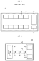
- FIG. 1 is a schematic perspective view of a general ESS 1
- FIG. 2 is a horizontal cross-sectional view of the ESS 1 of FIG. 1 .
- the ESS 1 includes a container 2, battery racks 3, a cooling member 4, etc.
- a plurality of battery racks 3 are located in the container 2.
- the plurality of battery racks 3 are adjacent to a side wall and an opposite side wall of the container 2 and are aligned along a length direction of the side walls.
- the cooling member 4 for cooling heat generated from the battery racks 3 is also located in the container 2.
- the cooling member 4 is essential.
- a fire control system for controlling a fire is also necessary.
- a fire extinguisher 5, a control panel 6, and a smoke detector 7 are provided in the container 2.
- the fire extinguisher 5 may be mechanically or manually used, or it may be determined whether a fire occurs, using only the smoke detector 7, and the fire extinguisher 5 may be driven through the control panel 6.
- the fire extinguisher 5 uses a carbon dioxide gas to extinguish the fire.
- smoke unrelated to a fire for example, smoke generated due to a temperature difference between the inside and the outside of the cooling member 4, water vapor, or external sand dust, may be recognized as a fire to incorrectly operate the fire extinguisher 5. If an extinguishing gas is discharged when a fire has not occurred, all internal elements of the container 2, e.g., a battery and a computer (not shown), become unusable.
- the present disclosure is designed to solve the problems of the related art, and therefore the present disclosure is directed to providing an energy storage system (ESS) capable of increasing precision of a fire control system to accurately determining and extinguishing a fire, and a fire control method of the ESS.
- ESS energy storage system
- an energy storage system including a container having an accommodation space therein, a heating, ventilation and air conditioning (HVAC) system configured to condition internal air of the container, to adjust an internal temperature of the container, and to adjust natural wind flowing into the container, and a fire control system provided in the container, wherein the fire control system includes a fire extinguisher and a control panel located in the accommodation space, a smoke detector, a heat detector, and a flame detector mounted in the container, and a duct smoke detector mounted in a duct of the HVAC system, and wherein the control panel has a mode for operating the fire extinguisher when all of the smoke detector, the heat detector, and the flame detector detect a fire, a mode for operating the fire extinguisher when the duct smoke detector detects a fire, and a mode for operating the fire extinguisher when a manipulation button is operated.
- HVAC heating, ventilation and air conditioning
- the fire extinguisher may be a valve-type extinguishing gas sprayer.
- the duct smoke detector may be mounted in at least one of an inlet duct and an outlet duct of the HVAC system.
- a first region and a second region may be set to divide the accommodation space into two, and a smoke detector, a heat detector, and a flame detector may be mounted in each region.
- the smoke detector and the heat detector may be mounted on a top wall (ceiling) of the container corresponding to an almost center part of each region, and the flame detector may be mounted on the top wall of the container near two facing side walls of the container.
- control panel may operate the fire extinguisher when all of three types of the detectors mounted in the same region detect a fire, or when all of different types of the detectors mounted in different regions detect a fire.
- the control panel may not operate the fire extinguisher but issue a fire alarm when all of the same type of the detectors mounted in different regions detect a fire.
- the ESS may further include battery racks located in the accommodation space and including a first battery rack group and a second battery rack group spaced apart from each other to face each other with respect to a center of the accommodation space
- the HVAC system may include an upper duct located on the accommodation space to supply a cooling fluid to a cooling space corresponding to a space between the first and second battery rack groups, a cooling unit located outside the accommodation space to cool the cooling fluid, and a fluid channel member having a passage space where the cooling fluid heated after cooling the battery racks moves to the cooling unit, the cooling unit may cool the heated cooling fluid received from the passage space, and then supply the cooled cooling fluid to the upper duct
- the duct smoke detector may be mounted in at least one of the upper duct and the fluid channel member.
- the container may include a first side wall, a second side wall located perpendicular to the first side wall, a third side wall facing the first side wall and located perpendicular to the second side wall, and a fourth side wall facing the second side wall and located perpendicular to the first and third side walls, and a plurality of cooling units may be provided outside the first and third side walls.
- the fluid channel member may include a partition located on the first and second battery rack groups, a pair of blocking plates configured to block a space between an outermost battery rack of the first or second battery rack group and the second or fourth side wall, and a pair of inner ducts configured to provide the passage space between the cooling unit and the second side wall or between the second side wall and the first or second battery rack group, and the duct smoke detector may be mounted in the inner ducts.
- a door generated on the second or fourth side wall and located adjacent to the first or third side wall may be provided on the container, and the inner ducts may be located at a higher height compared to a top surface of the door.
- the upper duct may include a first horizontal part located adjacent to the first side wall, a second horizontal part located adjacent to the third side wall in parallel with the first horizontal part, and a center part combined perpendicular to centers of the first and second horizontal parts, and the duct smoke detector may be mounted in the center part.
- the first horizontal part, the second horizontal part, and the center part may be combined with each other to form an I shape when viewed from above.
- the battery racks of the first battery rack group may be spaced apart from the second side wall by a certain distance and aligned along a first direction
- the battery racks of the second battery rack group may be spaced apart from the fourth side wall by a certain distance and aligned along the first direction
- the upper duct may include a supplier configured to supply the cooling fluid into the accommodation space and located on the center part
- the supplier may include an opening through which the cooling fluid flowing in the upper duct passes, a plurality of guide plates aligned in a center region of the opening, spaced apart from each other along the first direction, and provided in a rotatable form
- a guide plate controller configured to control the guide plates
- the duct smoke detector may be mounted on the supplier.
- a plurality of suppliers may be located on a bottom surface of the center part, and the plurality of suppliers may be spaced apart from each other by a certain distance along the first direction.
- the guide plate controller may control the guide plates to adjust a direction of supplying the cooling fluid into the cooling space through the opening.
- a fire control method of an energy storage system including a container having an accommodation space therein, a heating, ventilation and air conditioning (HVAC) system, and a fire extinguisher, the method including mounting a smoke detector, a heat detector, and a flame detector in the container, mounting a duct smoke detector in a duct of the HVAC system, and operating the fire extinguisher when all of the smoke detector, the heat detector, and the flame detector detect a fire, when the duct smoke detector detects a fire, or when a manipulation button is operated.
- HVAC heating, ventilation and air conditioning
- a first region and a second region may be set to divide the accommodation space into two, and a smoke detector, a heat detector, and a flame detector may be mounted in each region.
- the fire extinguisher is operated when all of three types of the detectors mounted in the same region detect a fire, or when all of different types of the detectors mounted in different regions detect a fire.
- the fire extinguisher may not be operated but a fire alarm may be issued when all of the same type of the detectors mounted in different regions detect a fire.
- a cause of a fire may be clearly identified.
- HVAC heating, ventilation and air conditioning
- a fire alarm may be accurately issued and a fire extinguisher may be accurately operated, thereby increasing reliability and accuracy of diagnosing a fire.
- evacuation and behavior rules for each level of the fire alarm may be specifically defined.
- an energy storage system (ESS) according to an embodiment of the present disclosure, since cooling units are provided outside a space where battery racks are accommodated, the number of battery racks located in a container may be maximized and thus an energy density of the ESS may be increased. Furthermore, since a space for cooling the battery racks is separate from a space where a heated cooling fluid moves, efficiency of cooling the battery racks may be increased. In addition, by mounting a duct smoke detector at various locations, when a fire occurs, reliability and accuracy of diagnosing the fire and discharging an extinguishing gas may be increased.
- FIG. 3 is a schematic block diagram of an energy storage system (ESS) 10 according to an embodiment of the present disclosure.
- FIG. 4 is a schematic block diagram for describing a fire control method of the ESS 10 illustrated in FIG. 3 .
- the ESS 10 includes a container 20 having an accommodation space therein, a heating, ventilation and air conditioning (HVAC) system 30 configured to condition internal air of the container 20, to adjust an internal temperature of the container 20, and to adjust natural wind flowing into the container 20, and a fire control system 40 provided in the container 20.
- HVAC heating, ventilation and air conditioning
- the fire control system 40 includes a fire extinguisher 45 and a control panel 50 located in the accommodation space, a smoke detector 55, a heat detector 60, and a flame detector 65 mounted in the container 20, and a duct smoke detector 70 mounted in a duct of the HVAC system 30.
- the control panel 50 has a mode for operating the fire extinguisher 45 when all of the smoke detector 55, the heat detector 60, and the flame detector 65 detect a fire (mode 1), a mode for operating the fire extinguisher 45 when the duct smoke detector 70 detects a fire (mode 2), and a mode for operating the fire extinguisher 45 when a manipulation button is operated (mode 3).
- the smoke detector 55 is a device for detecting smoke generated due to combustion before heat is generated by a fire, and an ionization smoke detector and a photoelectric smoke detector may be used.
- the smoke detector 55 is appropriate for an enclosed place where incomplete combustion easily occurs, e.g., the container 20, or a place which requires rapid direction, e.g., a place related to electricity.
- the heat detector 60 is operated when an ambient temperature is increased above a set reference temperature, and is divided into a rate-of-rise heat detector and a fixed-temperature heat detector.
- the rate-of-rise heat detector detects a rapid increase of the ambient temperature compared to a general temperature increase, and may use expansion of air and a variation in electrical resistance due to a temperature increase.
- the fixed-temperature heat detector is operated when the ambient temperature reaches a certain temperature, and may use a bimetal and a variation in thermal resistance. In the present disclosure, the heat detector 60 is used a lot to solve problems caused by malfunction of the smoke detector 55.
- the flame detector 65 includes an infrared (IR) spot flame detector for detecting IR light emitted from a flame of a fire, and an ultraviolet (UV) spot flame detector for detecting UV light emitted therefrom.
- IR infrared
- UV ultraviolet
- a UV/IR spot flame detector may be used.
- the flame detector 65 changes energy of a specific wavelength (IR, UV) emitted from the flame, into electrical energy and detects the electrical energy using a phenomenon that, when a material absorbs light, the material emits photoelectrons and thus electromotive force is generated.
- the flame detector 65 as well as the heat detector 60 are used a lot to solve problems caused by malfunction of the smoke detector 55.
- the fire extinguisher 45 may be a valve-type extinguishing gas sprayer.
- the duct smoke detector 70 may be mounted in at least one of an inlet duct and an outlet duct of the HVAC system 30.
- the ESS 10 includes the smoke detector 55, the heat detector 60, and the flame detector 65 connected in series, and is designed to discharge an extinguishing gas upon determining a fire when three types of fire alarms are input.
- duct smoke detector 70 in the duct of the HVAC system 30, smoke introduced through the duct may be detected and diagnosed as a fire to issue a fire alarm and discharge an extinguishing gas.
- a fire since only a smoke detector mounted on a top wall of a container is used, a fire may not be accurately diagnosed.
- reliability and accuracy of diagnosing a fire and discharging an extinguishing gas may be increased. Since three different types of fire detectors are used, a cause of a fire may be clearly identified. By further detecting smoke introduced through a duct, a fire alarm may be accurately issued and the fire extinguisher 45 may be accurately operated.
- FIG. 5 is a perspective view of an ESS 10' according to another embodiment of the present disclosure
- FIG. 6 is a horizontal cross-sectional view of the ESS 10' of FIG. 5 .
- the ESS 10' includes a container 100, battery racks 200, an upper duct 300, cooling units 400, and fluid channel members 500.
- the upper duct 300, the cooling units 400, and the fluid channel members 500 correspond to the HVAC system 30 described above in relation to FIG. 3 .
- the ESS 10' further includes a fire control system 600.
- the fire control system 600 includes a fire extinguisher 645 and a control panel 650 located in an accommodation space, smoke detectors 655a and 655b, heat detectors 660a and 660b, and flame detectors 665a and 665b mounted in the container 100, and a duct smoke detector 670 mounted in the upper duct 300.
- the fire extinguisher 645 may be provided on a side wall or a top wall inside the container 100.
- the fire extinguisher 645 may be provided to extinguish a fire when the fire occurs in the container 100.
- the fire extinguisher 645 may be a valve-type extinguishing gas sprayer.
- the container 100 has an accommodation space 101 therein.
- a plurality of battery racks 200 and the fluid channel members 500 are located in the accommodation space 101.
- the container 100 of the ESS 10' has an almost rectangular box shape.
- the container 100 has a first side wall 110, a second side wall 120, a third side wall 130, and a fourth side wall 140.
- a length direction of the second side wall 120 is referred to as a first direction 12.
- a direction perpendicular to the first direction 12 is referred to as a second direction 14.
- a direction perpendicular to both of the first and second directions 12 and 14 is referred to as a third direction 16.
- the first and third side walls 110 and 130 are spaced apart from each other by a certain distance along the first direction 12.
- the second and fourth side walls 120 and 140 are spaced apart from each other by a certain distance along the second direction 14.
- the second side wall 120 is located perpendicular to the first side wall 110.
- the second side wall 120 may extend longer than the first side wall 110.
- the third side wall 130 faces and is located in parallel with the first side wall 110.
- the third side wall 130 is located perpendicular to the second side wall 120.
- the fourth side wall 140 faces and is located in parallel with the second side wall 120.
- the fourth side wall 140 is located perpendicular to both of the first and third side walls 110 and 130.
- the first side wall 110, the second side wall 120, the third side wall 130, and the fourth side wall 140 may have lengths based on a container size.
- a container size For example, in a 40FT container, the length of the second and fourth side walls 120 and 140 (i.e., a container length) is 12.02M, and the length of the first and third side walls 110 and 130 (i.e., a container width) is 2.34M.
- a height of the container 100 is 2.38M.
- Doors 150 may be provided on the second side wall 120.
- a plurality of doors 150 may be provided.
- two doors 150 may be provided.
- One of the two doors 150 may be located adjacent to the first side wall 110, and the other one may be located adjacent to the third side wall 130.
- the battery racks 200 may be aligned along the first direction 12 at an inner side of the second side wall 120 facing a space between the two doors 150.
- doors 150 are provided on the second side wall 120 in an embodiment of the present disclosure, the doors 150 are not limited thereto and may be provided on the fourth side wall 140. Optionally, the doors 150 may be provided on both of the second and fourth side walls 120 and 140.
- the battery racks 200 are located in the accommodation space 101. A plurality of battery racks 200 are provided.
- the battery racks 200 include a first battery rack group 201 and a second battery rack group 202.
- the first and second battery rack groups 201 and 202 are located to face each other with respect to a center of the accommodation space 101.
- the first and second battery rack groups 201 and 202 are spaced apart from each other along the second direction 14.
- the first battery rack group 201 is spaced apart from the second side wall 120 by a certain distance.
- the battery racks 200 of the first battery rack group 201 are aligned along the first direction 12.
- the second battery rack group 202 is spaced apart from the fourth side wall 140 by a certain distance.
- the battery racks 200 of the second battery rack group 202 are aligned along the first direction 12.
- each of the first and second battery rack groups 201 and 202 includes eighteen battery racks 200 in an embodiment of the present disclosure, the number of battery racks 200 is not limited thereto.
- the first and second battery rack groups 201 and 202 are located in a cooling space 102 of the accommodation space 101.
- the cooling space 102 is defined as a space of the accommodation space 101 between the first and second battery rack groups 201 and 202 including a space where the first and second battery rack groups 201 and 202 are placed.
- a passage space 501 is defined as a space including a space between the first battery rack group 201 and the second side wall 120, a space between the second battery rack group 202 and the fourth side wall 140, and spaces between inner ducts 550 of the fluid channel members 500, which will be described below. That is, the passage space 501 is defined as a space where the fluid channel members 500 to be described below are provided.
- Each battery rack 200 has a plurality of battery modules.
- Each battery module may include a plurality of lithium ion batteries.
- Each battery rack 200 may include a rack housing, the battery modules, cooling fans, a battery controller, etc.
- the plurality of battery modules may be stacked on one another along the third direction 16.
- the cooling fans may adjust the flow of a cooling fluid in such a manner that the cooling fluid supplied to the cooling space 102 passes through the battery racks 200.
- a plurality of cooling fans may be stacked on one another along the third direction 16.
- the battery controller charges/discharges and protects the battery modules.
- the battery controller may control operation of the cooling fans.
- a first region and a second region are set to divide the accommodation space 101 into two, and a smoke detector, a heat detector, and a flame detector are mounted in each region.
- the smoke detector 655a, the heat detector 660a, and the flame detector 665a are mounted in the first region
- the smoke detector 655b, the heat detector 660b, and the flame detector 665b are mounted in the second region. Since the smoke detector, the heat detector, and the flame detector have fixed coverage areas depending on sizes thereof, the coverage areas are considered to mount the smoke detector, the heat detector, and the flame detector.
- the container 100 extends along the first direction 12.
- the accommodation space 101 may be divided into two along the second direction 14.
- the smoke detectors 655a and 655b and the heat detectors 660a and 660b may be mounted on the top wall of the container 100 corresponding to an almost center part of each region, and the flame detectors 665a and 665b may be mounted on the top wall of the container 100 near two facing side walls of the container 100, e.g., the first and third side walls 110 and 130 in the current embodiment.
- the locations of the detectors are determined to the most effectively diagnose and control a fire in consideration of the shape of the container 100, and the detectors are symmetrically mounted in the first and second regions as long as possible.
- the control panel 650 may operate the fire extinguisher 645 when all of three types of the detectors mounted in the same region detect a fire, or when all of different types of the detectors mounted in different regions detect a fire.
- the control panel 650 operates the fire extinguisher 645 when all of the smoke detector 655a, the heat detector 660a, and the flame detector 665a mounted in the first region detect a fire.
- the control panel 650 also operates the fire extinguisher 645 when all of the smoke detector 655b, the heat detector 660b, and the flame detector 665b mounted in the second region detect a fire.
- control panel 650 also operates the fire extinguisher 645 when all of the smoke detector 655a and the heat detector 660a mounted in the first region and the flame detector 665b mounted in the second region detect a fire.
- control panel 650 also operates the fire extinguisher 645 when all of the smoke detector 655a mounted in the first region and the heat detector 660b and the flame detector 665b mounted in the second region detect a fire.
- various combinations of the above-described examples are also possible.
- the control panel 650 may not operate the fire extinguisher 645 but issue a fire alarm when all of the same type of the detectors mounted in different regions detect a fire. For example, when both of the smoke detectors 655a and 655b detect a fire, when both of the heat detectors 660a and 660b detect a fire, and when both of the flame detectors 665a and 665b detect a fire, the control panel 650 may not operate the fire extinguisher 645 but issue a fire alarm. When three types of the detectors are mounted but only a single type of the detectors diagnose a fire, a possibility of a fire is low. Therefore, instead of immediately operating the fire extinguisher 645, a fire alarm may be issued such that a user may be prepared for a fire to occur later.
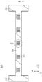
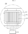
- FIG. 10 is a rear view of the upper duct 300 of FIG. 5
- FIG. 11 is a magnified view of a portion Z of FIG. 10 .
- the upper duct 300 supplies a cooling fluid to the accommodation space 101.
- the upper duct 300 is located on the container 100.
- the upper duct 300 is connected to a plurality of cooling units 400 to be described below.
- a space where the cooling fluid supplied from the cooling units 400 flows is provided in the upper duct 300.
- the upper duct 300 includes a cover 390, a first horizontal part 310, a second horizontal part 330, a center part 350, and suppliers 370.
- the duct smoke detector 670 may be mounted in the center part 350, and more particularly, on the suppliers 370.
- the duct smoke detector 670 may be provided as a rod-shaped detector mounted perpendicular to a flowing direction of the fluid in the duct to detect smoke included in the fluid.
- the cover 390 has an internal space.
- the cover 390 has an almost rectangular box shape.
- the cover 390 is located on the container 100.
- the cover 390 has a shape similar to the container 100, and has a lower height of the third direction 16 compared to the container 100.
- the first horizontal part 310, the second horizontal part 330, and the center part 350 are located in the internal space of the cover 390.
- the first horizontal part 310, the second horizontal part 330, and the center part 350 are connected to each other, and the cooling fluid flows in internal spaces thereof.
- the first horizontal part 310, the second horizontal part 330, and the center part 350 are combined with each other to form a Roman character I shape when viewed from above.
- the first horizontal part 310 is located adjacent to the first side wall 110.
- the first horizontal part 310 has a length direction along the second direction 14.
- the second horizontal part 330 is located adjacent to the third side wall 130.
- the second horizontal part 330 is located in parallel with the first horizontal part 310.
- the second horizontal part 330 has a length direction along the second direction 14.
- the center part 350 is combined perpendicular to centers of the first and second horizontal parts 310 and 330.
- the center part 350 has a length direction along the first direction 12.
- the suppliers 370 are located on a bottom surface of the upper duct 300.
- the suppliers 370 are located on the center part 350.
- the cooling fluid flowing in the center part 350 may pass through the suppliers 370.
- the suppliers 370 supply the cooling fluid to the accommodation space 101.
- a plurality of suppliers 370 are provided.
- the plurality of suppliers 370 are located on the bottom surface of the center part 350.
- the plurality of suppliers 370 are spaced apart from each other by a certain distance along the first direction 12.
- Each supplier 370 includes a frame 372, an opening 371, guide plates 373, and a guide plate controller 375.
- the frame 372 has an empty space at a center thereof.
- the frame 372 has a rectangular shape.
- the cooling fluid flowing in the upper duct 300 may pass through the opening 371.
- the frame 372 is mounted on the opening 371.
- the opening 371 has a rectangular shape.
- the guide plates 373 are arranged in a center region of the opening 371.
- the guide plates 373 may be provided as thin plates.
- a plurality of guide plates 373 are provided.
- the plurality of guide plates 373 are aligned and are spaced apart from each other along the first direction 12.
- the guide plates 373 may be provided in a rotatable form.
- the guide plate controller 375 adjusts rotation angles of the guide plates 373.
- the guide plate controller 375 controls the rotation angles of the guide plates 373 in such a manner that the cooling fluid passing through the suppliers 370 is supplied along the first direction 12 of the cooling space 102.
- the cooling fluid supplied to the cooling space 102 is not directly supplied to the battery racks 200 through the suppliers 370. Since the cooling fluid is not directly supplied to the battery racks 200 as described above, the cooling fluid may be prevented from swirling after hitting the battery racks 200. Furthermore, based on the above-described configuration, the cooling fluid is supplied from an upper part to a lower part of a space between the first and second battery rack groups 201 and 202, passes through the battery racks 200 to cool the battery racks 200, and then exits through cooling fans, thereby stably cooling the battery racks 200. In addition, the cooling fluid may be prevented from being supplied from the suppliers 370 directly to the battery racks 200 and from being concentrated on only upper parts of the battery racks 200.
- the cooling units 400 are located outside the accommodation space 101.
- the cooling units 400 may cool the heated cooling fluid.
- the cooling units 400 supply the cooled cooling fluid to the upper duct 300.
- the cooling units 400 may cool the cooling fluid received from the passage space 501 to be described below.
- a plurality of cooling units 400 are provided. According to an embodiment, four cooling units 400 may be provided. Two cooling units 400 may be mounted on the first side wall 110. The two cooling units 400 are spaced apart from each other by a certain distance along the second direction 14. The two cooling units 400 are connected to the first horizontal part 310, and may supply the cooling fluid to the first horizontal part 310.
- the other two cooling units 400 may be mounted on the third side wall 130.
- the two cooling units 400 are spaced apart from each other by a certain distance along the second direction 14.
- the two cooling units 400 are connected to the second horizontal part 330, and may supply the cooling fluid to the second horizontal part 330.
- the duct smoke detector 670 may also be mounted in the first horizontal part 310 and/or the second horizontal part 330 connected to the cooling units 400.
- Each cooling unit 400 may have a suction part.
- the suction part may suck out the cooling fluid of the passage space 501.
- the cooling unit 400 may be provided as (an outdoor unit of) an air conditioner including a suction part. Unlike this, the cooling unit 400 may be provided as a device capable of cooling the cooling fluid.
- the cooling member 4 is located in the container 2 and thus the number of battery racks 3 providable in the container 2 is limited.
- the limitation on the number of battery racks 3 reduces an energy density of the ESS 1.
- the cooling units 400 are located outside the container 100 and thus a larger internal space for accommodating the battery racks 200 may be ensured. Since the cooling units 400 are located outside, a larger number of battery racks 200 may be placed in the container 100. As such, an energy density of the ESS 10' may be increased.
- the energy density may be increased by setting a ratio of an area occupied by the battery racks 200 to a cross-sectional area of the container 100 to be equal to or greater than 2/3.
- the areas occupied by the container 100 and the battery racks 200 refer to those based on a horizontal cross-sectional view of the ESS 10' as illustrated in FIG. 6 .
- FIG. 7 is a vertical cross-sectional view of the ESS 10' of FIG. 6 , taken along a line A-A
- FIG. 8 is a vertical cross-sectional view of the ESS 10' of FIG. 6 , taken along a line B-B
- FIG. 9 is a vertical cross-sectional view of the ESS 10' of FIG. 6 , taken along a line C-C.
- the fluid channel members 500 provide the passage space 501 to move the cooling fluid used to cool the battery racks 200.
- two fluid channel members 500 are provided in the container 100.
- the two fluid channel members 500 are provided at different locations but have the same configuration. The following description is focused on the fluid channel member 500 located near the first battery rack group 201, as a representative example.
- the fluid channel member 500 includes a partition 510, blocking plates 530, and the inner ducts 550.
- the partition 510 is located on the first battery rack group 201.
- the partition 510 is located between the top wall of the container 100 and the first battery rack group 201.
- the partition 510 prevents the cooling fluid supplied from the upper duct 300, from moving to a space between the first battery rack group 201 and the second side wall 120.
- the partition 510 has a length direction along the first direction 12.
- the partition 510 may be provided as a plate.
- the blocking plates 530 block the space between the second side wall 120 and the first battery rack group 201.
- the blocking plates 530 are located between an outermost battery rack 200 of the first battery rack group 201 and the second side wall 120.
- a pair of blocking plates 530 are provided.
- the blocking plates 530 are located to face each other.
- the pair of blocking plates 530 are spaced apart from each other along the first direction 12.
- the blocking plates 530 may have the same height as the battery racks 200.
- the cooling fluid may flow in the inner ducts 550.
- a pair of inner ducts 550 are provided.
- the pair of inner ducts 550 are spaced apart from each other along the first direction 12.
- the inner ducts 550 connect the passage space 501 between the second side wall 120 and the first battery rack group 201.
- the inner ducts 550 are located at a higher height compared to top surfaces of the doors 150.
- the inner ducts 550 are located on the blocking plates 530.
- Each inner duct 550 may have a rectangular cross-section.
- An end of the inner duct 550 is connected to the cooling unit 400, and the other end thereof is connected to the space between the second side wall 120 and the first battery rack group 201.
- the inner duct 550 provides a space where the cooling fluid passed through the battery racks 200 moves to the cooling unit 400.
- the duct smoke detector 670 may also be mounted in the inner duct 550 or a connection part between the inner duct 550 and the cooling unit 400.
- the fluid channel member 500 provides the passage space 501 separate from the cooling space 102, using the partition 510, the blocking plates 530, and the inner ducts 550.
- the passage space 501 is a space where the cooling fluid moves to the cooling units 400 after the cold cooling fluid supplied to the cooling space 102 passes through the battery racks 200 to cool the battery racks 200.
- the cooling fluid may pass through each of battery modules stacked on one another and through spaces between the battery modules, to cool the battery racks 200.
- the passage space 501 When viewed from a center of the cooling space 102 toward the second side wall 120, the passage space 501 has a T shape.
- the passage space 501 is separate from the cooling space 102 and may allow the cooling fluid heated after passing through the battery racks 200, to move without being mixed with the cooling fluid of the cooling space 102, thereby increasing efficiency of cooling the battery racks 200.
- FIGS. 6 and 7 arrows schematically indicate directions in which the cooling fluid flows.
- the cooling fluid moves from the cooling units 400 to the upper duct 300.
- the cooling fluid moves to the upper duct 300 through the cooling units 400 located on the first or third side wall 110 or 130.
- the cooling fluid moves from the first horizontal part 310 to the center part 350, or from the second horizontal part 330 to the center part 350.
- the cooling fluid moves to the cooling space 102 through the suppliers 370 provided on the bottom surface of the center part 350.
- the cooling fluid moved to the cooling space 102 passes through the battery modules by the cooling fans of the battery racks 200.
- the cooling fluid cools the battery modules while passing through the battery modules.
- the cooling fluid may pass through each of the battery modules stacked on one another and through spaces between the battery modules, to cool the battery racks 200.
- the cooling fluid passed through the battery modules moves to the cooling units 400 through the passage space 501 separate from the cooling space 102.
- the heated cooling fluid moved to the cooling units 400 is cooled and supplied to the upper duct 300 again.
- the battery racks 200 may be cooled by circulating the cooling fluid through the cooling units 400, the upper duct 300, the cooling space 102, the battery modules, the passage space 501, and then the cooling units 400. In this process, since the cooling space 102 is separate from the passage space 501 through which the heated cooling fluid moves, efficiency of cooling the battery racks 200 may be increased.
- the smoke detector 7 since only the smoke detector 7 is used to determine whether a fire occurs, smoke unrelated to a fire may be recognized as a fire to incorrectly operate the fire extinguisher 5.
- the smoke detectors 655a and 655b, the heat detectors 660a and 660b, and the flame detectors 665a and 665b, and the duct smoke detector 670 since a serial combination of the smoke detectors 655a and 655b, the heat detectors 660a and 660b, and the flame detectors 665a and 665b, and the duct smoke detector 670 are used, reliability and accuracy of diagnosing a fire may be increased.
- the duct smoke detector 670 may be mounted in the upper duct 300, the fluid channel members 500, or connection parts between the fluid channel members 500 and the cooling units 400 to more accurately diagnose a fire in the container 100.
Landscapes
- Business, Economics & Management (AREA)
- Emergency Management (AREA)
- Chemical & Material Sciences (AREA)
- Health & Medical Sciences (AREA)
- Public Health (AREA)
- Engineering & Computer Science (AREA)
- General Physics & Mathematics (AREA)
- Physics & Mathematics (AREA)
- General Engineering & Computer Science (AREA)
- Combustion & Propulsion (AREA)
- Mechanical Engineering (AREA)
- Chemical Kinetics & Catalysis (AREA)
- Electrochemistry (AREA)
- General Chemical & Material Sciences (AREA)
- Analytical Chemistry (AREA)
- Manufacturing & Machinery (AREA)
- Secondary Cells (AREA)
- Battery Mounting, Suspending (AREA)
- Fire-Extinguishing By Fire Departments, And Fire-Extinguishing Equipment And Control Thereof (AREA)
Abstract
Description
- The present disclosure relates to an energy storage system (ESS) and a fire control method of the ESS, and more particularly, to an ESS capable of increasing precision of a fire control system, and a fire control method of the ESS. The present application claims priority to Korean Patent Application No.
10-2016-0120936 filed on September 21, 2016 - An energy storage system (ESS) refers to a device for storing electricity received from an external power source, e.g., a power plant, and transmitting the electricity to a desired place at a desired time. That is, the ESS is a high-capacity power storage device including power storage batteries, and is a device for storing electricity for use at desired place and a desired time. As such, the ESS currently attracts people's attention as a device for storing new and renewable energy (e.g., solar energy or wind energy).
- Currently, the ESS uses lithium ion batteries. General storage batteries lose some of stored electricity due to self-discharge, but the lithium ion batteries do not. The lithium ion batteries have a high power storage capacity per unit volume, and are able to store even a small amount of electricity generated by a solar power generator of a house. Unlike the other storage batteries, the lithium ion batteries do not have 'the memory effect in which the capacity of the storage batteries is reduced if they are recharged when not fully discharged'. For this reason, the lithium ion batteries are used to store electricity.
- In general, the ESS is configured by stacking battery modules each including lithium ion batteries, on one another in a container. A certain number of battery modules are stacked on one another in each of multilayered battery racks and are electrically connected to those of the other battery racks.
-
FIG. 1 is a schematic perspective view of ageneral ESS 1, andFIG. 2 is a horizontal cross-sectional view of theESS 1 ofFIG. 1 . - Referring to
FIGS. 1 and2 , theESS 1 includes acontainer 2,battery racks 3, acooling member 4, etc. - A plurality of
battery racks 3 are located in thecontainer 2. The plurality ofbattery racks 3 are adjacent to a side wall and an opposite side wall of thecontainer 2 and are aligned along a length direction of the side walls. Thecooling member 4 for cooling heat generated from thebattery racks 3 is also located in thecontainer 2. - Since a large number of battery modules are connected to each other and are densely included in the
ESS 1, a huge amount of heat is generated. To solve this problem, thecooling member 4 is essential. - Furthermore, since a fire which occurs in a worse case may lead to a big accident, a fire control system for controlling a fire is also necessary. In this regard, conventionally, a
fire extinguisher 5, acontrol panel 6, and a smoke detector 7 are provided in thecontainer 2. - To control a fire, the
fire extinguisher 5 may be mechanically or manually used, or it may be determined whether a fire occurs, using only the smoke detector 7, and thefire extinguisher 5 may be driven through thecontrol panel 6. Thefire extinguisher 5 uses a carbon dioxide gas to extinguish the fire. - However, since only the smoke detector 7 is used to determine whether a fire occurs, smoke unrelated to a fire, for example, smoke generated due to a temperature difference between the inside and the outside of the
cooling member 4, water vapor, or external sand dust, may be recognized as a fire to incorrectly operate thefire extinguisher 5. If an extinguishing gas is discharged when a fire has not occurred, all internal elements of thecontainer 2, e.g., a battery and a computer (not shown), become unusable. - Therefore, to solve the above problem, reliability and accuracy of operation of a fire extinguisher in an ESS should be increased and thus precision of a fire control system should also be increased.
- The present disclosure is designed to solve the problems of the related art, and therefore the present disclosure is directed to providing an energy storage system (ESS) capable of increasing precision of a fire control system to accurately determining and extinguishing a fire, and a fire control method of the ESS.
- These and other objects and advantages of the present disclosure may be understood from the following detailed description and will become more fully apparent from the exemplary embodiments of the present disclosure. Also, it will be easily understood that the objects and advantages of the present disclosure may be realized by the means shown in the appended claims and combinations thereof.
- In one aspect of the present disclosure, there is provided an energy storage system (ESS) including a container having an accommodation space therein, a heating, ventilation and air conditioning (HVAC) system configured to condition internal air of the container, to adjust an internal temperature of the container, and to adjust natural wind flowing into the container, and a fire control system provided in the container, wherein the fire control system includes a fire extinguisher and a control panel located in the accommodation space, a smoke detector, a heat detector, and a flame detector mounted in the container, and a duct smoke detector mounted in a duct of the HVAC system, and wherein the control panel has a mode for operating the fire extinguisher when all of the smoke detector, the heat detector, and the flame detector detect a fire, a mode for operating the fire extinguisher when the duct smoke detector detects a fire, and a mode for operating the fire extinguisher when a manipulation button is operated.
- The fire extinguisher may be a valve-type extinguishing gas sprayer.
- The duct smoke detector may be mounted in at least one of an inlet duct and an outlet duct of the HVAC system.
- In an embodiment, a first region and a second region may be set to divide the accommodation space into two, and a smoke detector, a heat detector, and a flame detector may be mounted in each region. In this case, the smoke detector and the heat detector may be mounted on a top wall (ceiling) of the container corresponding to an almost center part of each region, and the flame detector may be mounted on the top wall of the container near two facing side walls of the container.
- In the above-described configuration, the control panel may operate the fire extinguisher when all of three types of the detectors mounted in the same region detect a fire, or when all of different types of the detectors mounted in different regions detect a fire. The control panel may not operate the fire extinguisher but issue a fire alarm when all of the same type of the detectors mounted in different regions detect a fire.
- In another embodiment, the ESS may further include battery racks located in the accommodation space and including a first battery rack group and a second battery rack group spaced apart from each other to face each other with respect to a center of the accommodation space, the HVAC system may include an upper duct located on the accommodation space to supply a cooling fluid to a cooling space corresponding to a space between the first and second battery rack groups, a cooling unit located outside the accommodation space to cool the cooling fluid, and a fluid channel member having a passage space where the cooling fluid heated after cooling the battery racks moves to the cooling unit, the cooling unit may cool the heated cooling fluid received from the passage space, and then supply the cooled cooling fluid to the upper duct, and the duct smoke detector may be mounted in at least one of the upper duct and the fluid channel member.
- In this case, the container may include a first side wall, a second side wall located perpendicular to the first side wall, a third side wall facing the first side wall and located perpendicular to the second side wall, and a fourth side wall facing the second side wall and located perpendicular to the first and third side walls, and a plurality of cooling units may be provided outside the first and third side walls.
- In the above-described configuration, the fluid channel member may include a partition located on the first and second battery rack groups, a pair of blocking plates configured to block a space between an outermost battery rack of the first or second battery rack group and the second or fourth side wall, and a pair of inner ducts configured to provide the passage space between the cooling unit and the second side wall or between the second side wall and the first or second battery rack group, and the duct smoke detector may be mounted in the inner ducts.
- A door generated on the second or fourth side wall and located adjacent to the first or third side wall may be provided on the container, and the inner ducts may be located at a higher height compared to a top surface of the door.
- The upper duct may include a first horizontal part located adjacent to the first side wall, a second horizontal part located adjacent to the third side wall in parallel with the first horizontal part, and a center part combined perpendicular to centers of the first and second horizontal parts, and the duct smoke detector may be mounted in the center part.
- According to an embodiment, the first horizontal part, the second horizontal part, and the center part may be combined with each other to form an I shape when viewed from above.
- According to an embodiment, the battery racks of the first battery rack group may be spaced apart from the second side wall by a certain distance and aligned along a first direction, and the battery racks of the second battery rack group may be spaced apart from the fourth side wall by a certain distance and aligned along the first direction, the upper duct may include a supplier configured to supply the cooling fluid into the accommodation space and located on the center part, the supplier may include an opening through which the cooling fluid flowing in the upper duct passes, a plurality of guide plates aligned in a center region of the opening, spaced apart from each other along the first direction, and provided in a rotatable form, and a guide plate controller configured to control the guide plates, and the duct smoke detector may be mounted on the supplier.
- According to an embodiment, a plurality of suppliers may be located on a bottom surface of the center part, and the plurality of suppliers may be spaced apart from each other by a certain distance along the first direction.
- According to an embodiment, the guide plate controller may control the guide plates to adjust a direction of supplying the cooling fluid into the cooling space through the opening.
- In another aspect of the present disclosure, there is also provided a fire control method of an energy storage system (ESS) including a container having an accommodation space therein, a heating, ventilation and air conditioning (HVAC) system, and a fire extinguisher, the method including mounting a smoke detector, a heat detector, and a flame detector in the container, mounting a duct smoke detector in a duct of the HVAC system, and operating the fire extinguisher when all of the smoke detector, the heat detector, and the flame detector detect a fire, when the duct smoke detector detects a fire, or when a manipulation button is operated.
- Particularly, a first region and a second region may be set to divide the accommodation space into two, and a smoke detector, a heat detector, and a flame detector may be mounted in each region.
- The fire extinguisher is operated when all of three types of the detectors mounted in the same region detect a fire, or when all of different types of the detectors mounted in different regions detect a fire.
- The fire extinguisher may not be operated but a fire alarm may be issued when all of the same type of the detectors mounted in different regions detect a fire.
- According to the present disclosure, since three different types of fire detectors are used, a cause of a fire may be clearly identified. By further detecting smoke introduced through a duct of a heating, ventilation and air conditioning (HVAC) system, a fire alarm may be accurately issued and a fire extinguisher may be accurately operated, thereby increasing reliability and accuracy of diagnosing a fire. In addition, by breaking down levels of the fire alarm in detail, evacuation and behavior rules for each level of the fire alarm may be specifically defined.
- Particularly, in an energy storage system (ESS) according to an embodiment of the present disclosure, since cooling units are provided outside a space where battery racks are accommodated, the number of battery racks located in a container may be maximized and thus an energy density of the ESS may be increased. Furthermore, since a space for cooling the battery racks is separate from a space where a heated cooling fluid moves, efficiency of cooling the battery racks may be increased. In addition, by mounting a duct smoke detector at various locations, when a fire occurs, reliability and accuracy of diagnosing the fire and discharging an extinguishing gas may be increased.
- The accompanying drawings illustrate a preferred embodiment of the present disclosure and together with the foregoing disclosure, serve to provide further understanding of the technical features of the present disclosure, and thus, the present disclosure is not construed as being limited to the drawing.
-
FIG. 1 is a schematic perspective view of a general energy storage system (ESS). -
FIG. 2 is a horizontal cross-sectional view of the ESS ofFIG. 1 . -
FIG. 3 is a schematic block diagram of an ESS according to an embodiment of the present disclosure. -
FIG. 4 is a schematic block diagram for describing a fire control method of the ESS illustrated inFIG. 3 . -
FIG. 5 is a perspective view of an ESS according to another embodiment of the present disclosure. -
FIG. 6 is a horizontal cross-sectional view of the ESS ofFIG. 5 . -
FIG. 7 is a vertical cross-sectional view of the ESS ofFIG. 6 , taken along a line A-A. -
FIG. 8 is a vertical cross-sectional view of the ESS ofFIG. 6 , taken along a line B-B. -
FIG. 9 is a vertical cross-sectional view of the ESS ofFIG. 6 , taken along a line C-C. -
FIG. 10 is a rear view of an upper duct ofFIG. 5 . -
FIG. 11 is a magnified view of a portion Z ofFIG. 10 . - Hereinafter, preferred embodiments of the present disclosure will be described in detail with reference to the accompanying drawings. Prior to the description, it should be understood that the terms used in the specification and the appended claims should not be construed as limited to general and dictionary meanings, but interpreted based on the meanings and concepts corresponding to technical aspects of the present disclosure on the basis of the principle that the inventor is allowed to define terms appropriately for the best explanation. Therefore, the description proposed herein is just a preferable example for the purpose of illustrations only, not intended to limit the scope of the disclosure, so it should be understood that other equivalents and modifications could be made thereto without departing from the scope of the disclosure.
-
FIG. 3 is a schematic block diagram of an energy storage system (ESS) 10 according to an embodiment of the present disclosure.FIG. 4 is a schematic block diagram for describing a fire control method of theESS 10 illustrated inFIG. 3 . - Referring to
FIG. 3 , theESS 10 includes acontainer 20 having an accommodation space therein, a heating, ventilation and air conditioning (HVAC)system 30 configured to condition internal air of thecontainer 20, to adjust an internal temperature of thecontainer 20, and to adjust natural wind flowing into thecontainer 20, and afire control system 40 provided in thecontainer 20. - The
fire control system 40 includes afire extinguisher 45 and acontrol panel 50 located in the accommodation space, asmoke detector 55, aheat detector 60, and aflame detector 65 mounted in thecontainer 20, and aduct smoke detector 70 mounted in a duct of theHVAC system 30. - As shown in
FIG. 4 , thecontrol panel 50 has a mode for operating thefire extinguisher 45 when all of thesmoke detector 55, theheat detector 60, and theflame detector 65 detect a fire (mode 1), a mode for operating thefire extinguisher 45 when theduct smoke detector 70 detects a fire (mode 2), and a mode for operating thefire extinguisher 45 when a manipulation button is operated (mode 3). - The
smoke detector 55 is a device for detecting smoke generated due to combustion before heat is generated by a fire, and an ionization smoke detector and a photoelectric smoke detector may be used. Thesmoke detector 55 is appropriate for an enclosed place where incomplete combustion easily occurs, e.g., thecontainer 20, or a place which requires rapid direction, e.g., a place related to electricity. - The
heat detector 60 is operated when an ambient temperature is increased above a set reference temperature, and is divided into a rate-of-rise heat detector and a fixed-temperature heat detector. The rate-of-rise heat detector detects a rapid increase of the ambient temperature compared to a general temperature increase, and may use expansion of air and a variation in electrical resistance due to a temperature increase. The fixed-temperature heat detector is operated when the ambient temperature reaches a certain temperature, and may use a bimetal and a variation in thermal resistance. In the present disclosure, theheat detector 60 is used a lot to solve problems caused by malfunction of thesmoke detector 55. - The
flame detector 65 includes an infrared (IR) spot flame detector for detecting IR light emitted from a flame of a fire, and an ultraviolet (UV) spot flame detector for detecting UV light emitted therefrom. In addition, a UV/IR spot flame detector may be used. Theflame detector 65 changes energy of a specific wavelength (IR, UV) emitted from the flame, into electrical energy and detects the electrical energy using a phenomenon that, when a material absorbs light, the material emits photoelectrons and thus electromotive force is generated. In the present disclosure, theflame detector 65 as well as theheat detector 60 are used a lot to solve problems caused by malfunction of thesmoke detector 55. - The
fire extinguisher 45 may be a valve-type extinguishing gas sprayer. - The
duct smoke detector 70 may be mounted in at least one of an inlet duct and an outlet duct of theHVAC system 30. - As described above, the
ESS 10 includes thesmoke detector 55, theheat detector 60, and theflame detector 65 connected in series, and is designed to discharge an extinguishing gas upon determining a fire when three types of fire alarms are input. - In addition, by mounting the
duct smoke detector 70 in the duct of theHVAC system 30, smoke introduced through the duct may be detected and diagnosed as a fire to issue a fire alarm and discharge an extinguishing gas. - Conventionally, since only a smoke detector mounted on a top wall of a container is used, a fire may not be accurately diagnosed. However, according to the configuration of the present disclosure, when a fire occurs, reliability and accuracy of diagnosing a fire and discharging an extinguishing gas may be increased. Since three different types of fire detectors are used, a cause of a fire may be clearly identified. By further detecting smoke introduced through a duct, a fire alarm may be accurately issued and the
fire extinguisher 45 may be accurately operated. -
FIG. 5 is a perspective view of an ESS 10' according to another embodiment of the present disclosure, andFIG. 6 is a horizontal cross-sectional view of the ESS 10' ofFIG. 5 . - Referring to
FIGS. 5 and6 , the ESS 10' includes acontainer 100, battery racks 200, anupper duct 300, coolingunits 400, andfluid channel members 500. Theupper duct 300, the coolingunits 400, and thefluid channel members 500 correspond to theHVAC system 30 described above in relation toFIG. 3 . The ESS 10' further includes afire control system 600. Thefire control system 600 includes afire extinguisher 645 and acontrol panel 650 located in an accommodation space,smoke detectors heat detectors flame detectors container 100, and aduct smoke detector 670 mounted in theupper duct 300. Thefire extinguisher 645 may be provided on a side wall or a top wall inside thecontainer 100. Thefire extinguisher 645 may be provided to extinguish a fire when the fire occurs in thecontainer 100. Thefire extinguisher 645 may be a valve-type extinguishing gas sprayer. - The
container 100 has anaccommodation space 101 therein. A plurality ofbattery racks 200 and thefluid channel members 500 are located in theaccommodation space 101. Thecontainer 100 of the ESS 10' has an almost rectangular box shape. Thecontainer 100 has afirst side wall 110, asecond side wall 120, athird side wall 130, and afourth side wall 140. - Herein, a length direction of the
second side wall 120 is referred to as afirst direction 12. When viewed from above, a direction perpendicular to thefirst direction 12 is referred to as asecond direction 14. A direction perpendicular to both of the first andsecond directions third direction 16. - The first and
third side walls first direction 12. The second andfourth side walls second direction 14. - The
second side wall 120 is located perpendicular to thefirst side wall 110. Thesecond side wall 120 may extend longer than thefirst side wall 110. Thethird side wall 130 faces and is located in parallel with thefirst side wall 110. Thethird side wall 130 is located perpendicular to thesecond side wall 120. Thefourth side wall 140 faces and is located in parallel with thesecond side wall 120. Thefourth side wall 140 is located perpendicular to both of the first andthird side walls - The
first side wall 110, thesecond side wall 120, thethird side wall 130, and thefourth side wall 140 may have lengths based on a container size. For example, in a 40FT container, the length of the second andfourth side walls 120 and 140 (i.e., a container length) is 12.02M, and the length of the first andthird side walls 110 and 130 (i.e., a container width) is 2.34M. A height of thecontainer 100 is 2.38M. -
Doors 150 may be provided on thesecond side wall 120. A plurality ofdoors 150 may be provided. For example, twodoors 150 may be provided. One of the twodoors 150 may be located adjacent to thefirst side wall 110, and the other one may be located adjacent to thethird side wall 130. The battery racks 200 may be aligned along thefirst direction 12 at an inner side of thesecond side wall 120 facing a space between the twodoors 150. - Although the
doors 150 are provided on thesecond side wall 120 in an embodiment of the present disclosure, thedoors 150 are not limited thereto and may be provided on thefourth side wall 140. Optionally, thedoors 150 may be provided on both of the second andfourth side walls - The battery racks 200 are located in the
accommodation space 101. A plurality ofbattery racks 200 are provided. The battery racks 200 include a firstbattery rack group 201 and a secondbattery rack group 202. - The first and second
battery rack groups accommodation space 101. The first and secondbattery rack groups second direction 14. The firstbattery rack group 201 is spaced apart from thesecond side wall 120 by a certain distance. The battery racks 200 of the firstbattery rack group 201 are aligned along thefirst direction 12. - The second
battery rack group 202 is spaced apart from thefourth side wall 140 by a certain distance. The battery racks 200 of the secondbattery rack group 202 are aligned along thefirst direction 12. - Although each of the first and second
battery rack groups battery racks 200 in an embodiment of the present disclosure, the number ofbattery racks 200 is not limited thereto. - The first and second
battery rack groups cooling space 102 of theaccommodation space 101. - Herein, the
cooling space 102 is defined as a space of theaccommodation space 101 between the first and secondbattery rack groups battery rack groups passage space 501 is defined as a space including a space between the firstbattery rack group 201 and thesecond side wall 120, a space between the secondbattery rack group 202 and thefourth side wall 140, and spaces betweeninner ducts 550 of thefluid channel members 500, which will be described below. That is, thepassage space 501 is defined as a space where thefluid channel members 500 to be described below are provided. - Each
battery rack 200 has a plurality of battery modules. Each battery module may include a plurality of lithium ion batteries. Eachbattery rack 200 may include a rack housing, the battery modules, cooling fans, a battery controller, etc. - The plurality of battery modules may be stacked on one another along the
third direction 16. The cooling fans may adjust the flow of a cooling fluid in such a manner that the cooling fluid supplied to thecooling space 102 passes through the battery racks 200. A plurality of cooling fans may be stacked on one another along thethird direction 16. The battery controller charges/discharges and protects the battery modules. The battery controller may control operation of the cooling fans. - In the ESS 10', a first region and a second region are set to divide the
accommodation space 101 into two, and a smoke detector, a heat detector, and a flame detector are mounted in each region. In the current embodiment, thesmoke detector 655a, theheat detector 660a, and theflame detector 665a are mounted in the first region, and thesmoke detector 655b, theheat detector 660b, and theflame detector 665b are mounted in the second region. Since the smoke detector, the heat detector, and the flame detector have fixed coverage areas depending on sizes thereof, the coverage areas are considered to mount the smoke detector, the heat detector, and the flame detector. - Like the 40FT container mentioned above, the
container 100 extends along thefirst direction 12. To appropriately control a fire in theaccommodation space 101 of thecontainer 100, as illustrated inFIG. 5 , theaccommodation space 101 may be divided into two along thesecond direction 14. - The
smoke detectors heat detectors container 100 corresponding to an almost center part of each region, and theflame detectors container 100 near two facing side walls of thecontainer 100, e.g., the first andthird side walls container 100, and the detectors are symmetrically mounted in the first and second regions as long as possible. - In the above-described configuration, the
control panel 650 may operate thefire extinguisher 645 when all of three types of the detectors mounted in the same region detect a fire, or when all of different types of the detectors mounted in different regions detect a fire. For example, thecontrol panel 650 operates thefire extinguisher 645 when all of thesmoke detector 655a, theheat detector 660a, and theflame detector 665a mounted in the first region detect a fire. Thecontrol panel 650 also operates thefire extinguisher 645 when all of thesmoke detector 655b, theheat detector 660b, and theflame detector 665b mounted in the second region detect a fire. For instance, thecontrol panel 650 also operates thefire extinguisher 645 when all of thesmoke detector 655a and theheat detector 660a mounted in the first region and theflame detector 665b mounted in the second region detect a fire. As another example, thecontrol panel 650 also operates thefire extinguisher 645 when all of thesmoke detector 655a mounted in the first region and theheat detector 660b and theflame detector 665b mounted in the second region detect a fire. In addition, various combinations of the above-described examples are also possible. - The
control panel 650 may not operate thefire extinguisher 645 but issue a fire alarm when all of the same type of the detectors mounted in different regions detect a fire. For example, when both of thesmoke detectors heat detectors flame detectors control panel 650 may not operate thefire extinguisher 645 but issue a fire alarm. When three types of the detectors are mounted but only a single type of the detectors diagnose a fire, a possibility of a fire is low. Therefore, instead of immediately operating thefire extinguisher 645, a fire alarm may be issued such that a user may be prepared for a fire to occur later. - According to the above-described configuration, when a fire occurs, reliability and accuracy of diagnosing a fire and discharging an extinguishing gas may be increased. Since three different types of fire detectors are used, a cause of a fire may be clearly identified. By further detecting smoke introduced through a duct, a fire alarm may be accurately issued and the
fire extinguisher 645 may be accurately operated. In addition, by breaking down levels of the fire alarm in detail, evacuation and behavior rules for each level of the fire alarm may be specifically defined. -
FIG. 10 is a rear view of theupper duct 300 ofFIG. 5 , andFIG. 11 is a magnified view of a portion Z ofFIG. 10 . - Referring to
FIGS. 5 ,10 , and11 , theupper duct 300 supplies a cooling fluid to theaccommodation space 101. Theupper duct 300 is located on thecontainer 100. Theupper duct 300 is connected to a plurality of coolingunits 400 to be described below. A space where the cooling fluid supplied from the coolingunits 400 flows is provided in theupper duct 300. Theupper duct 300 includes acover 390, a firsthorizontal part 310, a secondhorizontal part 330, acenter part 350, andsuppliers 370. - The
duct smoke detector 670 may be mounted in thecenter part 350, and more particularly, on thesuppliers 370. Theduct smoke detector 670 may be provided as a rod-shaped detector mounted perpendicular to a flowing direction of the fluid in the duct to detect smoke included in the fluid. - The
cover 390 has an internal space. Thecover 390 has an almost rectangular box shape. Thecover 390 is located on thecontainer 100. Thecover 390 has a shape similar to thecontainer 100, and has a lower height of thethird direction 16 compared to thecontainer 100. The firsthorizontal part 310, the secondhorizontal part 330, and thecenter part 350 are located in the internal space of thecover 390. - The first
horizontal part 310, the secondhorizontal part 330, and thecenter part 350 are connected to each other, and the cooling fluid flows in internal spaces thereof. The firsthorizontal part 310, the secondhorizontal part 330, and thecenter part 350 are combined with each other to form a Roman character I shape when viewed from above. The firsthorizontal part 310 is located adjacent to thefirst side wall 110. The firsthorizontal part 310 has a length direction along thesecond direction 14. The secondhorizontal part 330 is located adjacent to thethird side wall 130. The secondhorizontal part 330 is located in parallel with the firsthorizontal part 310. The secondhorizontal part 330 has a length direction along thesecond direction 14. - The
center part 350 is combined perpendicular to centers of the first and secondhorizontal parts center part 350 has a length direction along thefirst direction 12. - The
suppliers 370 are located on a bottom surface of theupper duct 300. Thesuppliers 370 are located on thecenter part 350. The cooling fluid flowing in thecenter part 350 may pass through thesuppliers 370. Thesuppliers 370 supply the cooling fluid to theaccommodation space 101. A plurality ofsuppliers 370 are provided. The plurality ofsuppliers 370 are located on the bottom surface of thecenter part 350. The plurality ofsuppliers 370 are spaced apart from each other by a certain distance along thefirst direction 12. - Each
supplier 370 includes aframe 372, anopening 371, guideplates 373, and aguide plate controller 375. - The
frame 372 has an empty space at a center thereof. Theframe 372 has a rectangular shape. - The cooling fluid flowing in the
upper duct 300 may pass through theopening 371. Theframe 372 is mounted on theopening 371. Theopening 371 has a rectangular shape. - The
guide plates 373 are arranged in a center region of theopening 371. Theguide plates 373 may be provided as thin plates. A plurality ofguide plates 373 are provided. The plurality ofguide plates 373 are aligned and are spaced apart from each other along thefirst direction 12. Theguide plates 373 may be provided in a rotatable form. - The
guide plate controller 375 adjusts rotation angles of theguide plates 373. Theguide plate controller 375 controls the rotation angles of theguide plates 373 in such a manner that the cooling fluid passing through thesuppliers 370 is supplied along thefirst direction 12 of thecooling space 102. - The cooling fluid supplied to the
cooling space 102 is not directly supplied to the battery racks 200 through thesuppliers 370. Since the cooling fluid is not directly supplied to the battery racks 200 as described above, the cooling fluid may be prevented from swirling after hitting the battery racks 200. Furthermore, based on the above-described configuration, the cooling fluid is supplied from an upper part to a lower part of a space between the first and secondbattery rack groups suppliers 370 directly to the battery racks 200 and from being concentrated on only upper parts of the battery racks 200. - The cooling
units 400 are located outside theaccommodation space 101. The coolingunits 400 may cool the heated cooling fluid. The coolingunits 400 supply the cooled cooling fluid to theupper duct 300. The coolingunits 400 may cool the cooling fluid received from thepassage space 501 to be described below. - A plurality of cooling
units 400 are provided. According to an embodiment, four coolingunits 400 may be provided. Two coolingunits 400 may be mounted on thefirst side wall 110. The two coolingunits 400 are spaced apart from each other by a certain distance along thesecond direction 14. The two coolingunits 400 are connected to the firsthorizontal part 310, and may supply the cooling fluid to the firsthorizontal part 310. - The other two cooling
units 400 may be mounted on thethird side wall 130. The two coolingunits 400 are spaced apart from each other by a certain distance along thesecond direction 14. The two coolingunits 400 are connected to the secondhorizontal part 330, and may supply the cooling fluid to the secondhorizontal part 330. - The
duct smoke detector 670 may also be mounted in the firsthorizontal part 310 and/or the secondhorizontal part 330 connected to thecooling units 400. - Each
cooling unit 400 may have a suction part. The suction part may suck out the cooling fluid of thepassage space 501. According to an embodiment, thecooling unit 400 may be provided as (an outdoor unit of) an air conditioner including a suction part. Unlike this, thecooling unit 400 may be provided as a device capable of cooling the cooling fluid. - In the conventional technology described above in relation to
FIGS. 1 and2 , the coolingmember 4 is located in thecontainer 2 and thus the number ofbattery racks 3 providable in thecontainer 2 is limited. The limitation on the number ofbattery racks 3 reduces an energy density of theESS 1. On the other hand, in an embodiment of the present disclosure, the coolingunits 400 are located outside thecontainer 100 and thus a larger internal space for accommodating the battery racks 200 may be ensured. Since the coolingunits 400 are located outside, a larger number ofbattery racks 200 may be placed in thecontainer 100. As such, an energy density of the ESS 10' may be increased. - According to an embodiment of the present disclosure, the energy density may be increased by setting a ratio of an area occupied by the battery racks 200 to a cross-sectional area of the
container 100 to be equal to or greater than 2/3. Herein, the areas occupied by thecontainer 100 and the battery racks 200 refer to those based on a horizontal cross-sectional view of the ESS 10' as illustrated inFIG. 6 . -
FIG. 7 is a vertical cross-sectional view of the ESS 10' ofFIG. 6 , taken along a line A-A,FIG. 8 is a vertical cross-sectional view of the ESS 10' ofFIG. 6 , taken along a line B-B, andFIG. 9 is a vertical cross-sectional view of the ESS 10' ofFIG. 6 , taken along a line C-C. Referring toFIGS. 5 to 9 , thefluid channel members 500 provide thepassage space 501 to move the cooling fluid used to cool the battery racks 200. In an embodiment of the present disclosure, for example, twofluid channel members 500 are provided in thecontainer 100. The twofluid channel members 500 are provided at different locations but have the same configuration. The following description is focused on thefluid channel member 500 located near the firstbattery rack group 201, as a representative example. Thefluid channel member 500 includes apartition 510, blockingplates 530, and theinner ducts 550. - The
partition 510 is located on the firstbattery rack group 201. Thepartition 510 is located between the top wall of thecontainer 100 and the firstbattery rack group 201. Thepartition 510 prevents the cooling fluid supplied from theupper duct 300, from moving to a space between the firstbattery rack group 201 and thesecond side wall 120. Thepartition 510 has a length direction along thefirst direction 12. Thepartition 510 may be provided as a plate. - The blocking
plates 530 block the space between thesecond side wall 120 and the firstbattery rack group 201. The blockingplates 530 are located between anoutermost battery rack 200 of the firstbattery rack group 201 and thesecond side wall 120. A pair of blockingplates 530 are provided. The blockingplates 530 are located to face each other. The pair of blockingplates 530 are spaced apart from each other along thefirst direction 12. The blockingplates 530 may have the same height as the battery racks 200. - The cooling fluid may flow in the
inner ducts 550. A pair ofinner ducts 550 are provided. The pair ofinner ducts 550 are spaced apart from each other along thefirst direction 12. Theinner ducts 550 connect thepassage space 501 between thesecond side wall 120 and the firstbattery rack group 201. Theinner ducts 550 are located at a higher height compared to top surfaces of thedoors 150. Theinner ducts 550 are located on the blockingplates 530. Eachinner duct 550 may have a rectangular cross-section. An end of theinner duct 550 is connected to thecooling unit 400, and the other end thereof is connected to the space between thesecond side wall 120 and the firstbattery rack group 201. Theinner duct 550 provides a space where the cooling fluid passed through the battery racks 200 moves to thecooling unit 400. - The
duct smoke detector 670 may also be mounted in theinner duct 550 or a connection part between theinner duct 550 and thecooling unit 400. - As described above, the
fluid channel member 500 provides thepassage space 501 separate from thecooling space 102, using thepartition 510, the blockingplates 530, and theinner ducts 550. Thepassage space 501 is a space where the cooling fluid moves to the coolingunits 400 after the cold cooling fluid supplied to thecooling space 102 passes through the battery racks 200 to cool the battery racks 200. The cooling fluid may pass through each of battery modules stacked on one another and through spaces between the battery modules, to cool the battery racks 200. When viewed from a center of thecooling space 102 toward thesecond side wall 120, thepassage space 501 has a T shape. Thepassage space 501 is separate from thecooling space 102 and may allow the cooling fluid heated after passing through the battery racks 200, to move without being mixed with the cooling fluid of thecooling space 102, thereby increasing efficiency of cooling the battery racks 200. - The flow of the cooling fluid in the ESS 10' of
FIG. 3 will now be described. InFIGS. 6 and7 , arrows schematically indicate directions in which the cooling fluid flows. Referring toFIGS. 6 and7 , initially, the cooling fluid moves from the coolingunits 400 to theupper duct 300. The cooling fluid moves to theupper duct 300 through the coolingunits 400 located on the first orthird side wall horizontal part 310 to thecenter part 350, or from the secondhorizontal part 330 to thecenter part 350. While moving to thecenter part 350, the cooling fluid moves to thecooling space 102 through thesuppliers 370 provided on the bottom surface of thecenter part 350. The cooling fluid moved to thecooling space 102 passes through the battery modules by the cooling fans of the battery racks 200. The cooling fluid cools the battery modules while passing through the battery modules. For example, the cooling fluid may pass through each of the battery modules stacked on one another and through spaces between the battery modules, to cool the battery racks 200. The cooling fluid passed through the battery modules moves to the coolingunits 400 through thepassage space 501 separate from thecooling space 102. The heated cooling fluid moved to the coolingunits 400 is cooled and supplied to theupper duct 300 again. - In the conventional technology described above in relation to
FIGS. 1 and2 , heat is generated when the cooling fluid used to cool thebattery racks 3 is cooled by theinternal cooling member 4. The heat increases an internal temperature of thecontainer 2. As such, efficiency of cooling thebattery racks 3 is reduced. In addition, due to a large capacity of the coolingmember 4, an area occupied by the coolingmember 4 in thecontainer 2 is increased. On the other hand, in the above-described ESS 10' of the present disclosure, the battery racks 200 may be cooled by circulating the cooling fluid through the coolingunits 400, theupper duct 300, thecooling space 102, the battery modules, thepassage space 501, and then the coolingunits 400. In this process, since thecooling space 102 is separate from thepassage space 501 through which the heated cooling fluid moves, efficiency of cooling the battery racks 200 may be increased. - In the conventional technology described above in relation to
FIGS. 1 and2 , since only the smoke detector 7 is used to determine whether a fire occurs, smoke unrelated to a fire may be recognized as a fire to incorrectly operate thefire extinguisher 5. On the other hand, in the above-described ESS 10' of the present disclosure, since a serial combination of thesmoke detectors heat detectors flame detectors duct smoke detector 670 are used, reliability and accuracy of diagnosing a fire may be increased. Theduct smoke detector 670 may be mounted in theupper duct 300, thefluid channel members 500, or connection parts between thefluid channel members 500 and the coolingunits 400 to more accurately diagnose a fire in thecontainer 100. - The present disclosure has been described in detail. However, it should be understood that the detailed description and specific examples, while indicating preferred embodiments of the disclosure, are given by way of illustration only, since various changes and modifications within the scope of the disclosure will become apparent to those skilled in the art from this detailed description.
Claims (16)
- An energy storage system (ESS) comprising:a container having an accommodation space therein;a heating, ventilation and air conditioning (HVAC) system configured to condition internal air of the container, to adjust an internal temperature of the container, and to adjust natural wind flowing into the container; anda fire control system provided in the container,wherein the fire control system comprises:a fire extinguisher and a control panel located in the accommodation space;a smoke detector, a heat detector, and a flame detector mounted in the container; anda duct smoke detector mounted in a duct of the HVAC system, andwherein the control panel has:a mode for operating the fire extinguisher when all of the smoke detector, the heat detector, and the flame detector detect a fire;a mode for operating the fire extinguisher when the duct smoke detector detects a fire; anda mode for operating the fire extinguisher when a manipulation button is operated.
- The ESS of claim 1, wherein the fire extinguisher is a valve-type extinguishing gas sprayer.
- The ESS of claim 1, wherein the duct smoke detector is mounted in at least one of an inlet duct and an outlet duct of the HVAC system.
- The ESS of claim 1, wherein a first region and a second region are set to divide the accommodation space into two, and
wherein a smoke detector, a heat detector, and a flame detector are mounted in each region. - The ESS of claim 4, wherein the smoke detector and the heat detector are mounted on a top wall of the container corresponding to an almost center part of each region, and
wherein the flame detector is mounted on the top wall of the container near two facing side walls of the container. - The ESS of claim 4, wherein the control panel operates the fire extinguisher when all of three types of the detectors mounted in the same region detect a fire, or when all of different types of the detectors mounted in different regions detect a fire.
- The ESS of claim 4, wherein the control panel does not operate the fire extinguisher but issues a fire alarm when all of the same type of the detectors mounted in different regions detect a fire.
- The ESS of claim 1, further comprising battery racks located in the accommodation space and comprising a first battery rack group and a second battery rack group spaced apart from each other to face each other with respect to a center of the accommodation space,
wherein the HVAC system comprises:an upper duct located on the accommodation space to supply a cooling fluid to a cooling space corresponding to a space between the first and second battery rack groups;a cooling unit located outside the accommodation space to cool the cooling fluid; anda fluid channel member having a passage space where the cooling fluid heated after cooling the battery racks moves to the cooling unit,wherein the cooling unit cools the heated cooling fluid received from the passage space, and then supplies the cooled cooling fluid to the upper duct, andwherein the duct smoke detector is mounted in at least one of the upper duct and the fluid channel member. - The ESS of claim 8, wherein the container comprises:a first side wall;a second side wall located perpendicular to the first side wall;a third side wall facing the first side wall and located perpendicular to the second side wall; anda fourth side wall facing the second side wall and located perpendicular to the first and third side walls, andwherein a plurality of cooling units are provided outside the first and third side walls.
- The ESS of claim 9, wherein the fluid channel member comprises:a partition located on the first and second battery rack groups;a pair of blocking plates configured to block a space between an outermost battery rack of the first or second battery rack group and the second or fourth side wall; anda pair of inner ducts configured to provide the passage space between the cooling unit and the second side wall or between the second side wall and the first or second battery rack group, andwherein the duct smoke detector is mounted in the inner ducts.
- The ESS of claim 9, wherein the upper duct comprises:a first horizontal part located adjacent to the first side wall;a second horizontal part located adjacent to the third side wall in parallel with the first horizontal part; anda center part combined perpendicular to centers of the first and second horizontal parts, andwherein the duct smoke detector is mounted in the center part.
- The ESS of claim 11, wherein the battery racks of the first battery rack group are spaced apart from the second side wall by a certain distance and aligned along a first direction, and the battery racks of the second battery rack group are spaced apart from the fourth side wall by a certain distance and aligned along the first direction,
wherein the upper duct comprises a supplier configured to supply the cooling fluid into the accommodation space and located on the center part,
wherein the supplier comprises:an opening through which the cooling fluid flowing in the upper duct passes;a plurality of guide plates aligned in a center region of the opening, spaced apart from each other along the first direction, and provided in a rotatable form; anda guide plate controller configured to control the guide plates, andwherein the duct smoke detector is mounted on the supplier. - A fire control method of an energy storage system (ESS) comprising a container having an accommodation space therein, a heating, ventilation and air conditioning (HVAC) system, and a fire extinguisher, the method comprising:mounting a smoke detector, a heat detector, and a flame detector in the container;mounting a duct smoke detector in a duct of the HVAC system; andoperating the fire extinguisher when all of the smoke detector, the heat detector, and the flame detector detect a fire, when the duct smoke detector detects a fire, or when a manipulation button is operated.
- The fire control method of claim 13, wherein a first region and a second region are set to divide the accommodation space into two, and
wherein a smoke detector, a heat detector, and a flame detector are mounted in each region. - The fire control method of claim 14, wherein the fire extinguisher is operated when all of three types of the detectors mounted in the same region detect a fire, or when all of different types of the detectors mounted in different regions detect a fire.
- The fire control method of claim 14, wherein the fire extinguisher is not operated but a fire alarm is issued when all of the same type of the detectors mounted in different regions detect a fire.
Applications Claiming Priority (2)
| Application Number | Priority Date | Filing Date | Title |
|---|---|---|---|
| KR1020160120936A KR102053988B1 (en) | 2016-09-21 | 2016-09-21 | Energy storage system and method of fire managing for the energy storage system |
| PCT/KR2017/009441 WO2018056598A1 (en) | 2016-09-21 | 2017-08-29 | Energy storage system and fire management method for energy storage system |
Publications (3)
| Publication Number | Publication Date |
|---|---|
| EP3417915A1 true EP3417915A1 (en) | 2018-12-26 |
| EP3417915A4 EP3417915A4 (en) | 2019-02-27 |
| EP3417915B1 EP3417915B1 (en) | 2021-05-26 |
Family
ID=61690501
Family Applications (1)
| Application Number | Title | Priority Date | Filing Date |
|---|---|---|---|
| EP17853312.1A Active EP3417915B1 (en) | 2016-09-21 | 2017-08-29 | Energy storage system and fire control method of the energy storage system |
Country Status (5)
| Country | Link |
|---|---|
| US (1) | US10933263B2 (en) |
| EP (1) | EP3417915B1 (en) |
| KR (1) | KR102053988B1 (en) |
| AU (1) | AU2017330796B2 (en) |
| WO (1) | WO2018056598A1 (en) |
Cited By (1)
| Publication number | Priority date | Publication date | Assignee | Title |
|---|---|---|---|---|
| CN110124237A (en) * | 2019-04-27 | 2019-08-16 | 广州市锋安消防工程有限公司 | Fire control system |
Families Citing this family (41)
| Publication number | Priority date | Publication date | Assignee | Title |
|---|---|---|---|---|
| CN110350608A (en) * | 2018-04-03 | 2019-10-18 | 深圳市瑞能实业股份有限公司 | Cell managing device, method and system |
| CN108635700B (en) * | 2018-05-02 | 2021-05-25 | 蔚来(安徽)控股有限公司 | Safety protection system and safety protection method for charging and swapping station |
| CN109195368A (en) * | 2018-10-17 | 2019-01-11 | 郑州云海信息技术有限公司 | A kind of multizone container data center |
| US11376454B2 (en) | 2018-10-29 | 2022-07-05 | Air Distribution Technologies Ip, Llc | Integrated air distribution system and fire suppression system |
| CN109686888A (en) * | 2018-12-29 | 2019-04-26 | 广东康鼎电力科技有限公司 | A kind of novel battery cabinet |
| KR102137977B1 (en) | 2019-01-17 | 2020-08-04 | 주식회사 아이티엠반도체 | Fire Spread Prevention Structure of Energy Storage System for Photovoltaic Power Generation Facilities |
| KR102381692B1 (en) | 2019-02-21 | 2022-03-31 | 주식회사 엘지에너지솔루션 | Battery rack and energy storage system comprising the same |
| KR102747580B1 (en) * | 2019-02-28 | 2024-12-26 | 주식회사 엘지에너지솔루션 | Energy storage system |
| US10511001B1 (en) * | 2019-03-18 | 2019-12-17 | Sinexcel Inc. | Compact battery-based energy storage systems |
| KR102234336B1 (en) * | 2019-04-12 | 2021-03-31 | 주식회사 진성피엘티 | Constant temperature and humidity apparatus having a smoke detection function and controll method using the same |
| KR102134707B1 (en) * | 2019-05-02 | 2020-07-17 | 주식회사 이에스텍 | Ess for fire early prevention |
| KR20200140011A (en) * | 2019-06-05 | 2020-12-15 | 주식회사 엘지화학 | Battery rack and energy storage system comprising the same |
| CN110227223A (en) * | 2019-06-14 | 2019-09-13 | 郑州轻工业学院 | A kind of efficient fixed point location fire extinguishing system of container-type lithium ion battery energy storage system |
| CN110571380B (en) * | 2019-09-06 | 2022-02-22 | 北京海博思创科技股份有限公司 | Air duct and energy storage heat dissipation system |
| KR102812067B1 (en) | 2019-10-10 | 2025-05-23 | 주식회사 엘지에너지솔루션 | Battery pack having Gas detector using Mie scattering and Method for gas leakage detection using the same |
| AU2020380066B2 (en) * | 2019-11-08 | 2026-05-07 | Lg Energy Solution, Ltd. | Battery module, battery rack comprising same, and power storage device |
| KR102247044B1 (en) * | 2019-12-10 | 2021-04-30 | 호남대학교 산학협력단 | fire detecting and extinguishing apparatus for BESS |
| US20210218004A1 (en) * | 2020-01-10 | 2021-07-15 | Caterpillar Inc. | Battery fire suppression system |
| CN111249651B (en) * | 2020-01-18 | 2022-03-11 | 中国人民解放军海军潜艇学院 | Fire fighting device for ship shore power system and control method |
| KR102935720B1 (en) | 2020-01-30 | 2026-03-05 | 주식회사 엘지에너지솔루션 | Battery Pack Having Fire Extinguishing Unit, Battery Rack Including the Same and Power Storage System |
| CN111326824A (en) * | 2020-03-02 | 2020-06-23 | 深圳市科陆电子科技股份有限公司 | Fractional energy storage container |
| KR102868686B1 (en) | 2020-03-27 | 2025-10-02 | 주식회사 엘지에너지솔루션 | Battery pack and energy storage system comprising the battery pack |
| KR102172449B1 (en) | 2020-06-05 | 2020-10-30 | 김광섭 | Fire diffusion prevention apparatus for battery system using latent heat of phase change material, and battery system including the same |
| WO2022009152A1 (en) * | 2020-07-09 | 2022-01-13 | Johnson Controls Tyco IP Holdings LLP | Systems and methods for early controlled sprinkler activation |
| US11990388B2 (en) | 2020-08-06 | 2024-05-21 | Caterpillar Inc. | Pump-motor assembly for an energy storage system |
| US20220094013A1 (en) * | 2020-09-24 | 2022-03-24 | Battelle Memorial Institute | Automatic venting safety enclosure for grid-storage batteries |
| KR20220049357A (en) | 2020-10-14 | 2022-04-21 | 설영일 | Fire monitoring method and fire monitoring system of battery packs for energy storage device based on detection of a plurality of fire factor |
| KR102289709B1 (en) * | 2020-10-19 | 2021-08-13 | 퍼스트 유한회사 | Fire extinguishing system of battery loading of electric propulsion ship |
| CN112451880A (en) * | 2020-12-01 | 2021-03-09 | 南方电网调峰调频发电有限公司 | Fire-fighting system for energy storage power station |
| CN112618994A (en) * | 2020-12-14 | 2021-04-09 | 中汽研(天津)汽车工程研究院有限公司 | Fire extinguishing system applied to lithium ion battery energy storage device |
| US12157628B1 (en) | 2021-03-25 | 2024-12-03 | Energy Storage Response Group LLC | Systems and methods for purging smoke or other gasses from containers |
| KR102521729B1 (en) | 2021-04-21 | 2023-04-17 | 에이치디한국조선해양 주식회사 | System for controlling battery inside ship |
| KR102861701B1 (en) * | 2021-07-16 | 2025-09-17 | 주식회사 엘지에너지솔루션 | Battery pack frame, battery rack and energy storage system comprising the battery pack frame |
| KR20230025289A (en) | 2021-08-13 | 2023-02-21 | 주식회사 엘지에너지솔루션 | Energy storage system for fire suppression |
| EP4712203A3 (en) * | 2022-01-19 | 2026-05-27 | LG Energy Solution, Ltd. | Battery system |
| KR102679229B1 (en) * | 2022-01-19 | 2024-06-26 | 주식회사 엘지에너지솔루션 | Apparatus and method for fire monitoring |
| EP4358228B1 (en) | 2022-01-19 | 2025-11-19 | LG Energy Solution, Ltd. | Water injection unit and energy storage system including the same |
| KR102937814B1 (en) | 2023-04-10 | 2026-03-10 | 전억식 | An energy storage system |
| US20240380067A1 (en) | 2023-05-12 | 2024-11-14 | Caterpillar Inc. | Energy storage system deflagration and thermal propagation mitigation |
| KR102924438B1 (en) | 2024-03-04 | 2026-02-06 | (주)안국엔지니어링 | Fire Detection and Autonomous Fire Extinguishing System with Switchable of Direct Sprayed and Spread Sprayed |
| CN222940083U (en) * | 2024-06-24 | 2025-06-03 | 武汉亿纬储能有限公司 | Energy storage container |
Family Cites Families (17)
| Publication number | Priority date | Publication date | Assignee | Title |
|---|---|---|---|---|
| DE2423447C2 (en) | 1974-05-14 | 1982-11-25 | Siemens AG, 1000 Berlin und 8000 München | Automatic fire alarm and extinguishing equipment |
| US4227577A (en) * | 1976-07-26 | 1980-10-14 | Security Patrols Co., Ltd. | Fire-extinguishing system |
| US5486811A (en) * | 1994-02-09 | 1996-01-23 | The United States Of America As Represented By The Secretary Of The Navy | Fire detection and extinguishment system |
| US6897774B2 (en) * | 2003-05-07 | 2005-05-24 | Edwards Systems Technology, Inc. | Ambient condition detector with multipe sensors and single control unit |
| US7129847B2 (en) | 2003-08-06 | 2006-10-31 | Edwards Systems Technology, Inc. | Detector with dust filter and airflow monitor |
| JP2009010469A (en) | 2007-06-26 | 2009-01-15 | Oki Electric Ind Co Ltd | High-frequency receiver, high-frequency receiving method, lsi for high-frequency signal, and lsi for baseband signal |
| US7433794B1 (en) * | 2007-07-18 | 2008-10-07 | Tesla Motors, Inc. | Mitigation of propagation of thermal runaway in a multi-cell battery pack |
| JP2009110469A (en) * | 2007-11-01 | 2009-05-21 | Ntt Facilities Inc | Rack cooling system |
| US8547238B2 (en) * | 2010-06-30 | 2013-10-01 | Knowflame, Inc. | Optically redundant fire detector for false alarm rejection |
| KR101264338B1 (en) * | 2011-07-14 | 2013-05-14 | 삼성에스디아이 주식회사 | Rack housing assembly and energy storage apparatus having the same |
| JP5888907B2 (en) * | 2011-09-06 | 2016-03-22 | 株式会社日本設計 | Building, fire detection system, data center, and method of fire detection |
| US20130082115A1 (en) * | 2011-10-03 | 2013-04-04 | Matthew Ryan May | Remote Controlled Vent Register |
| ITBO20120229A1 (en) * | 2012-04-26 | 2013-10-27 | Spal Automotive Srl | ELECTRIC MACHINE. |
| KR101381592B1 (en) * | 2013-09-04 | 2014-04-04 | 채재훈 | Container for energy storage device |
| EP3055851B1 (en) * | 2013-10-07 | 2020-02-26 | Google LLC | Smart-home hazard detector providing context specific features and/or pre-alarm configurations |
| KR101550104B1 (en) * | 2013-12-04 | 2015-09-03 | 세방전지(주) | Large capacity energy storage system |
| KR101593762B1 (en) * | 2013-12-31 | 2016-02-12 | 주식회사 포스코아이씨티 | Battery Conditioning System |
-
2016
- 2016-09-21 KR KR1020160120936A patent/KR102053988B1/en active Active
-
2017
- 2017-08-29 US US16/079,481 patent/US10933263B2/en active Active
- 2017-08-29 WO PCT/KR2017/009441 patent/WO2018056598A1/en not_active Ceased
- 2017-08-29 EP EP17853312.1A patent/EP3417915B1/en active Active
- 2017-08-29 AU AU2017330796A patent/AU2017330796B2/en active Active
Cited By (1)
| Publication number | Priority date | Publication date | Assignee | Title |
|---|---|---|---|---|
| CN110124237A (en) * | 2019-04-27 | 2019-08-16 | 广州市锋安消防工程有限公司 | Fire control system |
Also Published As
| Publication number | Publication date |
|---|---|
| EP3417915A4 (en) | 2019-02-27 |
| US20190046820A1 (en) | 2019-02-14 |
| US10933263B2 (en) | 2021-03-02 |
| KR102053988B1 (en) | 2019-12-09 |
| KR20180032122A (en) | 2018-03-29 |
| EP3417915B1 (en) | 2021-05-26 |
| AU2017330796A1 (en) | 2018-09-27 |
| WO2018056598A1 (en) | 2018-03-29 |
| AU2017330796B2 (en) | 2023-02-02 |
Similar Documents
| Publication | Publication Date | Title |
|---|---|---|
| EP3417915B1 (en) | Energy storage system and fire control method of the energy storage system | |
| US12334531B2 (en) | Energy storage system | |
| US10164305B2 (en) | Energy storage apparatus and method for cooling the energy storage apparatus | |
| US11923517B2 (en) | Battery fire detection device and method, and energy storage system | |
| CN114976361B (en) | Energy storage container | |
| US11380947B2 (en) | Rack-type power supply device | |
| CN105101737B (en) | Data center module, data center cooling system and method | |
| CN111326824A (en) | Fractional energy storage container | |
| KR102699195B1 (en) | Liquid cooling integrated energy storage apparatus | |
| WO2015186343A1 (en) | Battery room | |
| US20110183599A1 (en) | Uninteruptable power supply enclosure and battery locker | |
| KR20200009603A (en) | An ESS Housing Being Capable of Cooling Effectively and Module Type Air Conditioning System Having the Same | |
| KR20200088178A (en) | Energy storage system | |
| KR102659500B1 (en) | Cooling device for energy storage system with fire detection flow path | |
| CN220087768U (en) | Testing equipment, battery testing systems and battery production lines | |
| CN214176939U (en) | Containerized energy storage device | |
| JP5263840B2 (en) | Air conditioning system | |
| CN112510780A (en) | Container type energy storage device | |
| KR102659501B1 (en) | Cooling device for energy storage system with fire detection module | |
| CN223941898U (en) | Container and energy storage container | |
| CN222261175U (en) | Energy storage container and energy storage system | |
| CN223427577U (en) | An air-cooled integrated cabinet | |
| CN224248861U (en) | Energy storage device, energy storage system and charging network | |
| KR20220132826A (en) | Battery cooling system | |
| CN110350247A (en) | Battery formation grading system |
Legal Events
| Date | Code | Title | Description |
|---|---|---|---|
| STAA | Information on the status of an ep patent application or granted ep patent |
Free format text: STATUS: THE INTERNATIONAL PUBLICATION HAS BEEN MADE |
|
| PUAI | Public reference made under article 153(3) epc to a published international application that has entered the european phase |
Free format text: ORIGINAL CODE: 0009012 |
|
| STAA | Information on the status of an ep patent application or granted ep patent |
Free format text: STATUS: REQUEST FOR EXAMINATION WAS MADE |
|
| 17P | Request for examination filed |
Effective date: 20180918 |
|
| AK | Designated contracting states |
Kind code of ref document: A1 Designated state(s): AL AT BE BG CH CY CZ DE DK EE ES FI FR GB GR HR HU IE IS IT LI LT LU LV MC MK MT NL NO PL PT RO RS SE SI SK SM TR |
|
| AX | Request for extension of the european patent |
Extension state: BA ME |
|
| A4 | Supplementary search report drawn up and despatched |
Effective date: 20190129 |
|
| RIC1 | Information provided on ipc code assigned before grant |
Ipc: G08B 17/12 20060101ALI20190123BHEP Ipc: H01M 2/10 20060101ALI20190123BHEP Ipc: A62C 37/38 20060101ALI20190123BHEP Ipc: G08B 17/10 20060101ALI20190123BHEP Ipc: F24F 11/00 20180101ALI20190123BHEP Ipc: A62C 35/68 20060101ALI20190123BHEP Ipc: A62C 3/16 20060101AFI20190123BHEP |
|
| DAV | Request for validation of the european patent (deleted) | ||
| DAX | Request for extension of the european patent (deleted) | ||
| STAA | Information on the status of an ep patent application or granted ep patent |
Free format text: STATUS: EXAMINATION IS IN PROGRESS |
|
| 17Q | First examination report despatched |
Effective date: 20200722 |
|
| RIC1 | Information provided on ipc code assigned before grant |
Ipc: A62C 35/68 20060101ALI20210111BHEP Ipc: A62C 37/38 20060101ALI20210111BHEP Ipc: G08B 17/10 20060101ALI20210111BHEP Ipc: H01M 50/20 20210101ALI20210111BHEP Ipc: A62C 3/16 20060101AFI20210111BHEP Ipc: G08B 17/12 20060101ALI20210111BHEP Ipc: F24F 11/00 20180101ALI20210111BHEP |
|
| GRAP | Despatch of communication of intention to grant a patent |
Free format text: ORIGINAL CODE: EPIDOSNIGR1 |
|
| STAA | Information on the status of an ep patent application or granted ep patent |
Free format text: STATUS: GRANT OF PATENT IS INTENDED |
|
| INTG | Intention to grant announced |
Effective date: 20210301 |
|
| GRAS | Grant fee paid |
Free format text: ORIGINAL CODE: EPIDOSNIGR3 |
|
| GRAA | (expected) grant |
Free format text: ORIGINAL CODE: 0009210 |
|
| STAA | Information on the status of an ep patent application or granted ep patent |
Free format text: STATUS: THE PATENT HAS BEEN GRANTED |
|
| AK | Designated contracting states |
Kind code of ref document: B1 Designated state(s): AL AT BE BG CH CY CZ DE DK EE ES FI FR GB GR HR HU IE IS IT LI LT LU LV MC MK MT NL NO PL PT RO RS SE SI SK SM TR |
|
| REG | Reference to a national code |
Ref country code: GB Ref legal event code: FG4D |
|
| REG | Reference to a national code |
Ref country code: CH Ref legal event code: EP |
|
| REG | Reference to a national code |
Ref country code: AT Ref legal event code: REF Ref document number: 1395617 Country of ref document: AT Kind code of ref document: T Effective date: 20210615 |
|
| REG | Reference to a national code |
Ref country code: DE Ref legal event code: R096 Ref document number: 602017039451 Country of ref document: DE |
|
| REG | Reference to a national code |
Ref country code: IE Ref legal event code: FG4D |
|
| REG | Reference to a national code |
Ref country code: LT Ref legal event code: MG9D |
|
| REG | Reference to a national code |
Ref country code: AT Ref legal event code: MK05 Ref document number: 1395617 Country of ref document: AT Kind code of ref document: T Effective date: 20210526 |
|
| PG25 | Lapsed in a contracting state [announced via postgrant information from national office to epo] |
Ref country code: FI Free format text: LAPSE BECAUSE OF FAILURE TO SUBMIT A TRANSLATION OF THE DESCRIPTION OR TO PAY THE FEE WITHIN THE PRESCRIBED TIME-LIMIT Effective date: 20210526 Ref country code: LT Free format text: LAPSE BECAUSE OF FAILURE TO SUBMIT A TRANSLATION OF THE DESCRIPTION OR TO PAY THE FEE WITHIN THE PRESCRIBED TIME-LIMIT Effective date: 20210526 Ref country code: HR Free format text: LAPSE BECAUSE OF FAILURE TO SUBMIT A TRANSLATION OF THE DESCRIPTION OR TO PAY THE FEE WITHIN THE PRESCRIBED TIME-LIMIT Effective date: 20210526 Ref country code: AT Free format text: LAPSE BECAUSE OF FAILURE TO SUBMIT A TRANSLATION OF THE DESCRIPTION OR TO PAY THE FEE WITHIN THE PRESCRIBED TIME-LIMIT Effective date: 20210526 Ref country code: BG Free format text: LAPSE BECAUSE OF FAILURE TO SUBMIT A TRANSLATION OF THE DESCRIPTION OR TO PAY THE FEE WITHIN THE PRESCRIBED TIME-LIMIT Effective date: 20210826 |
|
| REG | Reference to a national code |
Ref country code: NL Ref legal event code: MP Effective date: 20210526 |
|
| PG25 | Lapsed in a contracting state [announced via postgrant information from national office to epo] |
Ref country code: SE Free format text: LAPSE BECAUSE OF FAILURE TO SUBMIT A TRANSLATION OF THE DESCRIPTION OR TO PAY THE FEE WITHIN THE PRESCRIBED TIME-LIMIT Effective date: 20210526 Ref country code: RS Free format text: LAPSE BECAUSE OF FAILURE TO SUBMIT A TRANSLATION OF THE DESCRIPTION OR TO PAY THE FEE WITHIN THE PRESCRIBED TIME-LIMIT Effective date: 20210526 Ref country code: PT Free format text: LAPSE BECAUSE OF FAILURE TO SUBMIT A TRANSLATION OF THE DESCRIPTION OR TO PAY THE FEE WITHIN THE PRESCRIBED TIME-LIMIT Effective date: 20210927 Ref country code: NO Free format text: LAPSE BECAUSE OF FAILURE TO SUBMIT A TRANSLATION OF THE DESCRIPTION OR TO PAY THE FEE WITHIN THE PRESCRIBED TIME-LIMIT Effective date: 20210826 Ref country code: LV Free format text: LAPSE BECAUSE OF FAILURE TO SUBMIT A TRANSLATION OF THE DESCRIPTION OR TO PAY THE FEE WITHIN THE PRESCRIBED TIME-LIMIT Effective date: 20210526 Ref country code: PL Free format text: LAPSE BECAUSE OF FAILURE TO SUBMIT A TRANSLATION OF THE DESCRIPTION OR TO PAY THE FEE WITHIN THE PRESCRIBED TIME-LIMIT Effective date: 20210526 Ref country code: IS Free format text: LAPSE BECAUSE OF FAILURE TO SUBMIT A TRANSLATION OF THE DESCRIPTION OR TO PAY THE FEE WITHIN THE PRESCRIBED TIME-LIMIT Effective date: 20210926 Ref country code: GR Free format text: LAPSE BECAUSE OF FAILURE TO SUBMIT A TRANSLATION OF THE DESCRIPTION OR TO PAY THE FEE WITHIN THE PRESCRIBED TIME-LIMIT Effective date: 20210827 |
|
| PG25 | Lapsed in a contracting state [announced via postgrant information from national office to epo] |
Ref country code: NL Free format text: LAPSE BECAUSE OF FAILURE TO SUBMIT A TRANSLATION OF THE DESCRIPTION OR TO PAY THE FEE WITHIN THE PRESCRIBED TIME-LIMIT Effective date: 20210526 |
|
| RAP2 | Party data changed (patent owner data changed or rights of a patent transferred) |
Owner name: LG ENERGY SOLUTION LTD. |
|
| PG25 | Lapsed in a contracting state [announced via postgrant information from national office to epo] |
Ref country code: RO Free format text: LAPSE BECAUSE OF FAILURE TO SUBMIT A TRANSLATION OF THE DESCRIPTION OR TO PAY THE FEE WITHIN THE PRESCRIBED TIME-LIMIT Effective date: 20210526 Ref country code: CZ Free format text: LAPSE BECAUSE OF FAILURE TO SUBMIT A TRANSLATION OF THE DESCRIPTION OR TO PAY THE FEE WITHIN THE PRESCRIBED TIME-LIMIT Effective date: 20210526 Ref country code: DK Free format text: LAPSE BECAUSE OF FAILURE TO SUBMIT A TRANSLATION OF THE DESCRIPTION OR TO PAY THE FEE WITHIN THE PRESCRIBED TIME-LIMIT Effective date: 20210526 Ref country code: SK Free format text: LAPSE BECAUSE OF FAILURE TO SUBMIT A TRANSLATION OF THE DESCRIPTION OR TO PAY THE FEE WITHIN THE PRESCRIBED TIME-LIMIT Effective date: 20210526 Ref country code: SM Free format text: LAPSE BECAUSE OF FAILURE TO SUBMIT A TRANSLATION OF THE DESCRIPTION OR TO PAY THE FEE WITHIN THE PRESCRIBED TIME-LIMIT Effective date: 20210526 Ref country code: EE Free format text: LAPSE BECAUSE OF FAILURE TO SUBMIT A TRANSLATION OF THE DESCRIPTION OR TO PAY THE FEE WITHIN THE PRESCRIBED TIME-LIMIT Effective date: 20210526 Ref country code: ES Free format text: LAPSE BECAUSE OF FAILURE TO SUBMIT A TRANSLATION OF THE DESCRIPTION OR TO PAY THE FEE WITHIN THE PRESCRIBED TIME-LIMIT Effective date: 20210526 |
|
| REG | Reference to a national code |
Ref country code: DE Ref legal event code: R097 Ref document number: 602017039451 Country of ref document: DE |
|
| RAP4 | Party data changed (patent owner data changed or rights of a patent transferred) |
Owner name: LG ENERGY SOLUTION, LTD. |
|
| REG | Reference to a national code |
Ref country code: CH Ref legal event code: PL |
|
| PLBE | No opposition filed within time limit |
Free format text: ORIGINAL CODE: 0009261 |
|
| STAA | Information on the status of an ep patent application or granted ep patent |
Free format text: STATUS: NO OPPOSITION FILED WITHIN TIME LIMIT |
|
| PG25 | Lapsed in a contracting state [announced via postgrant information from national office to epo] |
Ref country code: MC Free format text: LAPSE BECAUSE OF FAILURE TO SUBMIT A TRANSLATION OF THE DESCRIPTION OR TO PAY THE FEE WITHIN THE PRESCRIBED TIME-LIMIT Effective date: 20210526 |
|
| REG | Reference to a national code |
Ref country code: BE Ref legal event code: MM Effective date: 20210831 |
|
| PG25 | Lapsed in a contracting state [announced via postgrant information from national office to epo] |
Ref country code: LI Free format text: LAPSE BECAUSE OF NON-PAYMENT OF DUE FEES Effective date: 20210831 Ref country code: CH Free format text: LAPSE BECAUSE OF NON-PAYMENT OF DUE FEES Effective date: 20210831 |
|
| 26N | No opposition filed |
Effective date: 20220301 |
|
| PG25 | Lapsed in a contracting state [announced via postgrant information from national office to epo] |
Ref country code: IS Free format text: LAPSE BECAUSE OF FAILURE TO SUBMIT A TRANSLATION OF THE DESCRIPTION OR TO PAY THE FEE WITHIN THE PRESCRIBED TIME-LIMIT Effective date: 20210926 Ref country code: LU Free format text: LAPSE BECAUSE OF NON-PAYMENT OF DUE FEES Effective date: 20210829 Ref country code: AL Free format text: LAPSE BECAUSE OF FAILURE TO SUBMIT A TRANSLATION OF THE DESCRIPTION OR TO PAY THE FEE WITHIN THE PRESCRIBED TIME-LIMIT Effective date: 20210526 |
|
| PG25 | Lapsed in a contracting state [announced via postgrant information from national office to epo] |
Ref country code: IT Free format text: LAPSE BECAUSE OF FAILURE TO SUBMIT A TRANSLATION OF THE DESCRIPTION OR TO PAY THE FEE WITHIN THE PRESCRIBED TIME-LIMIT Effective date: 20210526 Ref country code: IE Free format text: LAPSE BECAUSE OF NON-PAYMENT OF DUE FEES Effective date: 20210829 Ref country code: BE Free format text: LAPSE BECAUSE OF NON-PAYMENT OF DUE FEES Effective date: 20210831 |
|
| REG | Reference to a national code |
Ref country code: DE Ref legal event code: R081 Ref document number: 602017039451 Country of ref document: DE Owner name: LG ENERGY SOLUTION, LTD., KR Free format text: FORMER OWNER: LG CHEM, LTD., SEOUL, KR |
|
| P01 | Opt-out of the competence of the unified patent court (upc) registered |
Effective date: 20230512 |
|
| PG25 | Lapsed in a contracting state [announced via postgrant information from national office to epo] |
Ref country code: CY Free format text: LAPSE BECAUSE OF FAILURE TO SUBMIT A TRANSLATION OF THE DESCRIPTION OR TO PAY THE FEE WITHIN THE PRESCRIBED TIME-LIMIT Effective date: 20210526 |
|
| PG25 | Lapsed in a contracting state [announced via postgrant information from national office to epo] |
Ref country code: HU Free format text: LAPSE BECAUSE OF FAILURE TO SUBMIT A TRANSLATION OF THE DESCRIPTION OR TO PAY THE FEE WITHIN THE PRESCRIBED TIME-LIMIT; INVALID AB INITIO Effective date: 20170829 |
|
| REG | Reference to a national code |
Ref country code: GB Ref legal event code: 732E Free format text: REGISTERED BETWEEN 20230901 AND 20230906 |
|
| PG25 | Lapsed in a contracting state [announced via postgrant information from national office to epo] |
Ref country code: MK Free format text: LAPSE BECAUSE OF FAILURE TO SUBMIT A TRANSLATION OF THE DESCRIPTION OR TO PAY THE FEE WITHIN THE PRESCRIBED TIME-LIMIT Effective date: 20210526 |
|
| PG25 | Lapsed in a contracting state [announced via postgrant information from national office to epo] |
Ref country code: MT Free format text: LAPSE BECAUSE OF FAILURE TO SUBMIT A TRANSLATION OF THE DESCRIPTION OR TO PAY THE FEE WITHIN THE PRESCRIBED TIME-LIMIT Effective date: 20210526 |
|
| PGFP | Annual fee paid to national office [announced via postgrant information from national office to epo] |
Ref country code: DE Payment date: 20250721 Year of fee payment: 9 |
|
| PGFP | Annual fee paid to national office [announced via postgrant information from national office to epo] |
Ref country code: GB Payment date: 20250722 Year of fee payment: 9 |
|
| PGFP | Annual fee paid to national office [announced via postgrant information from national office to epo] |
Ref country code: FR Payment date: 20250725 Year of fee payment: 9 |
|
| PG25 | Lapsed in a contracting state [announced via postgrant information from national office to epo] |
Ref country code: TR Free format text: LAPSE BECAUSE OF FAILURE TO SUBMIT A TRANSLATION OF THE DESCRIPTION OR TO PAY THE FEE WITHIN THE PRESCRIBED TIME-LIMIT Effective date: 20210526 |