EP3417428B1 - Procédé de détermination d'authenticité à l'aide d'images présentant une parallaxe - Google Patents
Procédé de détermination d'authenticité à l'aide d'images présentant une parallaxe Download PDFInfo
- Publication number
- EP3417428B1 EP3417428B1 EP17708884.6A EP17708884A EP3417428B1 EP 3417428 B1 EP3417428 B1 EP 3417428B1 EP 17708884 A EP17708884 A EP 17708884A EP 3417428 B1 EP3417428 B1 EP 3417428B1
- Authority
- EP
- European Patent Office
- Prior art keywords
- image
- hologram
- captured
- parallax
- parallax image
- Prior art date
- Legal status (The legal status is an assumption and is not a legal conclusion. Google has not performed a legal analysis and makes no representation as to the accuracy of the status listed.)
- Active
Links
- 238000000034 method Methods 0.000 title claims description 59
- 239000013598 vector Substances 0.000 claims description 201
- 230000001747 exhibiting effect Effects 0.000 claims description 30
- 238000004590 computer program Methods 0.000 claims description 7
- 230000000007 visual effect Effects 0.000 claims description 5
- 230000008859 change Effects 0.000 description 21
- 238000004891 communication Methods 0.000 description 18
- 238000010200 validation analysis Methods 0.000 description 16
- 230000008569 process Effects 0.000 description 12
- 230000003287 optical effect Effects 0.000 description 10
- 238000005259 measurement Methods 0.000 description 7
- 230000006870 function Effects 0.000 description 6
- 230000007246 mechanism Effects 0.000 description 5
- 238000012795 verification Methods 0.000 description 5
- 230000000052 comparative effect Effects 0.000 description 4
- 108010010803 Gelatin Proteins 0.000 description 3
- 238000010586 diagram Methods 0.000 description 3
- 229920000159 gelatin Polymers 0.000 description 3
- 239000008273 gelatin Substances 0.000 description 3
- 235000019322 gelatine Nutrition 0.000 description 3
- 235000011852 gelatine desserts Nutrition 0.000 description 3
- 238000001093 holography Methods 0.000 description 3
- 238000012545 processing Methods 0.000 description 3
- 230000004044 response Effects 0.000 description 3
- 238000004422 calculation algorithm Methods 0.000 description 2
- 238000005094 computer simulation Methods 0.000 description 2
- 229940079593 drug Drugs 0.000 description 2
- 239000003814 drug Substances 0.000 description 2
- 239000000839 emulsion Substances 0.000 description 2
- 239000011521 glass Substances 0.000 description 2
- 238000004519 manufacturing process Methods 0.000 description 2
- 238000013178 mathematical model Methods 0.000 description 2
- 230000010076 replication Effects 0.000 description 2
- 230000003068 static effect Effects 0.000 description 2
- 230000003190 augmentative effect Effects 0.000 description 1
- 235000013361 beverage Nutrition 0.000 description 1
- 230000001413 cellular effect Effects 0.000 description 1
- 238000004883 computer application Methods 0.000 description 1
- 230000001419 dependent effect Effects 0.000 description 1
- 238000013461 design Methods 0.000 description 1
- 230000008034 disappearance Effects 0.000 description 1
- 238000005516 engineering process Methods 0.000 description 1
- 239000011888 foil Substances 0.000 description 1
- 235000013305 food Nutrition 0.000 description 1
- 238000005286 illumination Methods 0.000 description 1
- 239000000976 ink Substances 0.000 description 1
- 230000003993 interaction Effects 0.000 description 1
- 239000003550 marker Substances 0.000 description 1
- 239000000463 material Substances 0.000 description 1
- 230000003278 mimic effect Effects 0.000 description 1
- 238000004806 packaging method and process Methods 0.000 description 1
- 230000008447 perception Effects 0.000 description 1
- 238000007639 printing Methods 0.000 description 1
- 238000001454 recorded image Methods 0.000 description 1
- 230000003362 replicative effect Effects 0.000 description 1
- 229910052709 silver Inorganic materials 0.000 description 1
- 239000004332 silver Substances 0.000 description 1
- -1 silver halide Chemical class 0.000 description 1
- 238000004088 simulation Methods 0.000 description 1
- 239000007787 solid Substances 0.000 description 1
- 210000003813 thumb Anatomy 0.000 description 1
Images

Classifications
-
- G—PHYSICS
- G03—PHOTOGRAPHY; CINEMATOGRAPHY; ANALOGOUS TECHNIQUES USING WAVES OTHER THAN OPTICAL WAVES; ELECTROGRAPHY; HOLOGRAPHY
- G03H—HOLOGRAPHIC PROCESSES OR APPARATUS
- G03H1/00—Holographic processes or apparatus using light, infrared or ultraviolet waves for obtaining holograms or for obtaining an image from them; Details peculiar thereto
- G03H1/04—Processes or apparatus for producing holograms
- G03H1/0402—Recording geometries or arrangements
- G03H1/041—Optical element in the object space affecting the object beam, not otherwise provided for
-
- G—PHYSICS
- G07—CHECKING-DEVICES
- G07D—HANDLING OF COINS OR VALUABLE PAPERS, e.g. TESTING, SORTING BY DENOMINATIONS, COUNTING, DISPENSING, CHANGING OR DEPOSITING
- G07D7/00—Testing specially adapted to determine the identity or genuineness of valuable papers or for segregating those which are unacceptable, e.g. banknotes that are alien to a currency
- G07D7/003—Testing specially adapted to determine the identity or genuineness of valuable papers or for segregating those which are unacceptable, e.g. banknotes that are alien to a currency using security elements
- G07D7/0032—Testing specially adapted to determine the identity or genuineness of valuable papers or for segregating those which are unacceptable, e.g. banknotes that are alien to a currency using security elements using holograms
-
- B—PERFORMING OPERATIONS; TRANSPORTING
- B42—BOOKBINDING; ALBUMS; FILES; SPECIAL PRINTED MATTER
- B42D—BOOKS; BOOK COVERS; LOOSE LEAVES; PRINTED MATTER CHARACTERISED BY IDENTIFICATION OR SECURITY FEATURES; PRINTED MATTER OF SPECIAL FORMAT OR STYLE NOT OTHERWISE PROVIDED FOR; DEVICES FOR USE THEREWITH AND NOT OTHERWISE PROVIDED FOR; MOVABLE-STRIP WRITING OR READING APPARATUS
- B42D25/00—Information-bearing cards or sheet-like structures characterised by identification or security features; Manufacture thereof
- B42D25/30—Identification or security features, e.g. for preventing forgery
- B42D25/328—Diffraction gratings; Holograms
-
- G—PHYSICS
- G03—PHOTOGRAPHY; CINEMATOGRAPHY; ANALOGOUS TECHNIQUES USING WAVES OTHER THAN OPTICAL WAVES; ELECTROGRAPHY; HOLOGRAPHY
- G03H—HOLOGRAPHIC PROCESSES OR APPARATUS
- G03H1/00—Holographic processes or apparatus using light, infrared or ultraviolet waves for obtaining holograms or for obtaining an image from them; Details peculiar thereto
- G03H1/0005—Adaptation of holography to specific applications
- G03H1/0011—Adaptation of holography to specific applications for security or authentication
-
- G—PHYSICS
- G03—PHOTOGRAPHY; CINEMATOGRAPHY; ANALOGOUS TECHNIQUES USING WAVES OTHER THAN OPTICAL WAVES; ELECTROGRAPHY; HOLOGRAPHY
- G03H—HOLOGRAPHIC PROCESSES OR APPARATUS
- G03H1/00—Holographic processes or apparatus using light, infrared or ultraviolet waves for obtaining holograms or for obtaining an image from them; Details peculiar thereto
- G03H1/02—Details of features involved during the holographic process; Replication of holograms without interference recording
- G03H1/024—Hologram nature or properties
- G03H1/0244—Surface relief holograms
-
- G—PHYSICS
- G03—PHOTOGRAPHY; CINEMATOGRAPHY; ANALOGOUS TECHNIQUES USING WAVES OTHER THAN OPTICAL WAVES; ELECTROGRAPHY; HOLOGRAPHY
- G03H—HOLOGRAPHIC PROCESSES OR APPARATUS
- G03H1/00—Holographic processes or apparatus using light, infrared or ultraviolet waves for obtaining holograms or for obtaining an image from them; Details peculiar thereto
- G03H1/04—Processes or apparatus for producing holograms
- G03H1/18—Particular processing of hologram record carriers, e.g. for obtaining blazed holograms
-
- G—PHYSICS
- G06—COMPUTING; CALCULATING OR COUNTING
- G06K—GRAPHICAL DATA READING; PRESENTATION OF DATA; RECORD CARRIERS; HANDLING RECORD CARRIERS
- G06K19/00—Record carriers for use with machines and with at least a part designed to carry digital markings
- G06K19/06—Record carriers for use with machines and with at least a part designed to carry digital markings characterised by the kind of the digital marking, e.g. shape, nature, code
- G06K19/08—Record carriers for use with machines and with at least a part designed to carry digital markings characterised by the kind of the digital marking, e.g. shape, nature, code using markings of different kinds or more than one marking of the same kind in the same record carrier, e.g. one marking being sensed by optical and the other by magnetic means
- G06K19/10—Record carriers for use with machines and with at least a part designed to carry digital markings characterised by the kind of the digital marking, e.g. shape, nature, code using markings of different kinds or more than one marking of the same kind in the same record carrier, e.g. one marking being sensed by optical and the other by magnetic means at least one kind of marking being used for authentication, e.g. of credit or identity cards
- G06K19/16—Record carriers for use with machines and with at least a part designed to carry digital markings characterised by the kind of the digital marking, e.g. shape, nature, code using markings of different kinds or more than one marking of the same kind in the same record carrier, e.g. one marking being sensed by optical and the other by magnetic means at least one kind of marking being used for authentication, e.g. of credit or identity cards the marking being a hologram or diffraction grating
-
- G—PHYSICS
- G03—PHOTOGRAPHY; CINEMATOGRAPHY; ANALOGOUS TECHNIQUES USING WAVES OTHER THAN OPTICAL WAVES; ELECTROGRAPHY; HOLOGRAPHY
- G03H—HOLOGRAPHIC PROCESSES OR APPARATUS
- G03H1/00—Holographic processes or apparatus using light, infrared or ultraviolet waves for obtaining holograms or for obtaining an image from them; Details peculiar thereto
- G03H1/0005—Adaptation of holography to specific applications
- G03H1/0011—Adaptation of holography to specific applications for security or authentication
- G03H2001/0016—Covert holograms or holobjects requiring additional knowledge to be perceived, e.g. holobject reconstructed only under IR illumination
-
- G—PHYSICS
- G03—PHOTOGRAPHY; CINEMATOGRAPHY; ANALOGOUS TECHNIQUES USING WAVES OTHER THAN OPTICAL WAVES; ELECTROGRAPHY; HOLOGRAPHY
- G03H—HOLOGRAPHIC PROCESSES OR APPARATUS
- G03H1/00—Holographic processes or apparatus using light, infrared or ultraviolet waves for obtaining holograms or for obtaining an image from them; Details peculiar thereto
- G03H1/04—Processes or apparatus for producing holograms
- G03H1/0402—Recording geometries or arrangements
- G03H2001/0421—Parallax aspect
Definitions
- This disclosure relates to authentication, brand protection, anti-counterfeiting, and to methods for authentication designed to be used with images that exhibit parallax such as certain types of holograms. More specifically, the disclosure relates to methods for validation based on holograms exhibiting parallax, and to the use of holographic elements for conveying information or data. Authentication methods using particular devices such as smart phone cameras and flashes, communication interfaces, computer processors, and downloadable applications for smart phones, tablets, and computers are also disclosed.
- Authentication, brand protection and anti-counterfeiting have a wide range of applications. These relate generally to verifying the authenticity of commercial goods, consumable products including food and beverages, medicines, clothing and accessories, electronic devices, currency, passports and other government or non-governmental ID cards (e.g., academic IDs, corporate IDs), tickets, key cards, documents, and other uses where authentication, brand protection, or anti-counterfeiting is necessary or desirable.
- the term "authentication” may be used to refer to all related applications such as brand protection and anti-counterfeiting collectively. Authentication works by verifying the provenance of an item or document and therefore verifying that the item or document is not a counterfeit, knockoff or fake.
- Holograms may contain overt and/or covert elements.
- Simple holograms such as two-dimensional embossed or color-shift holograms, have overt elements such as appearance or disappearance of an image or color shift as the hologram is pivoted at different angles to incident light.
- Simple holograms commonly applied on credit cards are examples of two-dimensional embossed holograms.
- Such holographic elements are overt and rely on subjective or intuitive verification by a human observer.
- an object to be imaged is illuminated with collimated light (e.g., from a laser) and a light sensitive recording medium (e.g., a photographic plate) is positioned so as to receive light reflected from the object.
- a light sensitive recording medium e.g., a photographic plate
- Each point on the object reflects light to the entire recording medium, and each point on the medium receives light from the entire object.
- This beam of reflected light is known as the object beam.
- a portion of the collimated light is beamed by a mirror directly to the medium, by-passing the object. This beam is known as the reference beam.
- What is recorded on the recording medium is the interference pattern that results from the interaction of the reference beam and the object beam impinging on the medium.
- the processed recording medium is subsequently illuminated and observed appropriately, the light from the illuminating source is diffracted by the hologram to reproduce the wave-front that originally reached the medium from the object, so that the hologram resembles a window through which a virtual image of the object is observed in full three-dimensional form, complete with parallax.
- EP-A-1852752 discloses a verification apparatus and a verification method for verifying a recording medium on which a picture whose state changes under various conditions is formed, by use of an optical material such as, for example, a hologram and a diffraction grating. Said picture exhibits parallax and contains two target identifiers.
- a method for determining the validity of a parallax image comprising: receiving a captured two-dimensional image of a parallax image having at least three target identifiers, wherein at least two target identifiers are located at different depth planes in the parallax image; identifying the at least three target identifiers in the captured two-dimensional image of the parallax image and determining the spatial relationship between the at least three target identifiers in the two-dimensional image of the parallax image; comparing the spatial relationship of the at least three target identifiers in the captured two-dimensional image of the parallax image against a predetermined spatial relationship of the at least three target identifiers that indicates authenticity; and adjudicating the authenticity of the parallax image based on the degree of difference between the spatial relationship of the at least three target identifiers in the captured two-dimensional image of the parallax image and the predetermined spatial relationship of the at least three target identifiers.
- the spatial relationship of the at least three target identifiers comprises a ratio of the lengths of vectors linking the target identifiers.
- the spatial relationship of the at least three target identifiers in the captured two-dimensional image of the parallax image may typically be compared against a digital model of the spatial relationship between the at least three target identifiers of a master parallax image against which the authenticity of the parallax image is being determined.
- a digital model may typically comprise the predetermined spatial relationship.
- the method may further comprise the steps of capturing multiple two-dimensional images of a master parallax image taken from multiple perspectives; identifying at least three target identifiers in each captured two-dimensional image of the master parallax image; creating a plurality of vectors linking the target identifiers in each of the captured two-dimensional images of the master parallax image; determining the ratio of the lengths of the vectors linking the target identifiers in each of the captured two-dimensional images of the master parallax image; and generating a digital model for the master parallax image that captures the ratio of the lengths of the vectors linking the target identifiers in each of the captured two-dimensional images of the master parallax image, wherein the digital model comprises the predetermined spatial relationship.
- These steps are typically carried out before the receiving of the captured two-dimensional image of a parallax image.
- the method may comprise the steps of creating a plurality of vectors linking the target identifiers in the captured two-dimensional image of the parallax image; and determining the ratio of the lengths of the vectors linking the target identifiers in the captured two-dimensional image of the parallax image, and wherein the step of comparing comprises: accessing the digital model for the master parallax image; comparing the vector length ratio determined from the captured two-dimensional image of the parallax image against vector length ratio values captured in the digital model for the master parallax image; and calculating the difference between the vector length ratio for the captured two-dimensional image of the parallax image and the vector length ratios from the digital model for the master parallax image; and wherein the adjudicating is based on whether the difference between the vector length ratio from the captured two-dimensional image of the parallax image and the vector length ratio from the digital model for the master parallax image are within an acceptable predetermined margin.
- the method may further comprise determining the perspective relative to the master parallax image of each of the multiple two-dimensional images of the master parallax image; and inputting the coordinates of the perspective of each two-dimensional image of the master parallax image into the digital model for the master parallax image and associating such perspective coordinates with the ratio of the lengths of the vectors linking the target identifiers in each of the respective two-dimensional images of the master parallax image captured in the digital model for the master parallax image; determining the perspective relative to the parallax image of the received captured two-dimensional image of the parallax image; comparing the vector length ratio determined from the captured two-dimensional image of the parallax image against the vector length ratio captured from the digital model for the master parallax image for substantially the same perspective coordinates; calculating the difference between the vector length ratio for the captured two-dimensional image of the parallax image and the corresponding vector length ratio of the digital model for substantially the same perspective coordinates; and adjudicating the authenticity of the
- the method may further comprise receiving a plurality of captured two-dimensional images of a parallax image; identifying at least three target identifiers in each of the plurality of captured two-dimensional images of the parallax image; creating a plurality of vectors linking the target identifiers in each of the plurality of captured two-dimensional images of the parallax image; and determining the ratio of the lengths of the vectors linking the target identifiers in each of the plurality of captured two-dimensional images of the parallax image; accessing the digital model for the master parallax image; comparing the vector length ratio determined from each of the plurality of captured two-dimensional images of the parallax image against vector length ratio values captured in the digital model for the master parallax image; calculating the difference between the vector length ratio for each of the plurality of captured two-dimensional images of the parallax image and the vector length ratios from the digital model for the master parallax image; and adjudicating the authenticity of the captured two-dimensional image of the parall
- the method may comprise comparing the vector length ratio determined from each of the plurality of captured two-dimensional images of the parallax image against the corresponding vector length ratio in the digital model for substantially the same perspective coordinates as each of the plurality of captured two-dimensional images of the parallax image.
- the parallax image is an image exhibiting parallax generated from a hologram.
- the parallax image exhibits full parallax.
- the master parallax image is typically an image exhibiting parallax generated from a hologram.
- the master parallax image exhibits full parallax.
- At least one of the parallax image and the master parallax image may comprise a lenticular image or a micro-lens image.
- the parallax image may be provided on a document of value such as a passport, identity card, driving licence, bank card, bank note or security label.
- a document of value such as a passport, identity card, driving licence, bank card, bank note or security label.
- a computer program product comprising one or more computer-readable media having thereon computer-executable instructions that, when executed by one or more processors of a computer, causes the one or more processors of the computer to perform the method of the first aspect.
- a digitally executable authentication system for determining the validly of a parallax image comprising: a scanning device for receiving a captured two-dimensional image of a parallax image having at least three target identifiers, and one or more processors configured to perform the method of the first aspect.
- a digitally executable authentication system for determining the validly of a parallax image that executes the steps comprising: receiving multiple two-dimensional images of a master parallax image taken from multiple perspectives; identifying at least two pairs of target identifiers in each two-dimensional image of the master parallax image; creating a plurality of vectors linking the target identifiers in each of the two-dimensional images of the master parallax image; determining the ratio of the lengths of the vectors linking the target identifiers in each of the two-dimensional images of the master parallax image; and generating a digital model that captures the ratio of the lengths of the vectors linking the target identifiers in each of the two-dimensional images of the master parallax image; receiving a captured two-dimensional image of a possible duplicate of the master parallax image; identifying at least two pairs of target identifiers in the captured two-dimensional image of the possible duplicate of the master parallax image; creating a plurality of vectors linking
- the parallax image is an image exhibiting parallax generated from a hologram.
- the parallax image exhibits full parallax.
- the master parallax image is typically an image exhibiting parallax generated from a hologram.
- the master parallax image exhibits full parallax.
- At least one of the parallax image and the master parallax image may comprise a lenticular image or a micro-lens image.
- the digitally executable authentication system may execute the steps of capturing the perspective relative to the master parallax image of each of the multiple two-dimensional images of the master parallax image; and inputting the respective coordinates of the perspective of each two-dimensional image of the master parallax image into the digital model and associating such perspective coordinates with the ratio of the lengths of the vectors linking the target identifiers in each of the respective two-dimensional images of the master parallax image; determining the perspective relative to the possible duplicate of the master parallax image of the received captured two-dimensional image of a possible duplicate of the master parallax image; comparing the vector length ratio determined from the captured two-dimensional image of the possible duplicate of the master parallax image against vector length ratio values captured in the digital model for substantially the same perspective coordinates; calculating the difference between the vector length ratio for the captured two-dimensional image of the possible duplicate of the master parallax image and the corresponding vector length ratio of the digital model for substantially the same perspective coordinates; and adjudicating the authenticity of the
- the digitally executable authentication system may execute the steps of receiving a plurality of captured two-dimensional images of a possible duplicate of the master parallax image; identifying at least two pairs of target identifiers in each of the plurality of captured two-dimensional images of the possible duplicate of the master parallax image; creating a plurality of vectors linking the target identifiers in each of the plurality of captured two-dimensional images of the possible duplicate of the master parallax image; and determining the comparative ratio of the lengths of the vectors linking the target identifiers in each of the plurality of captured two-dimensional images of the possible duplicate of the master parallax image; determining the perspective relative to the possible duplicate of the master parallax image of each of the plurality of received captured two-dimensional images of a possible duplicate of the master parallax image; comparing the vector length ratio determined from each of the plurality of captured two-dimensional images of the possible duplicate of the master parallax image against corresponding vector length ratio in the digital model for substantially the same perspective coordinates as
- a digitally executable authentication system for determining the validity of a document of value comprising a parallax image, comprising the system of the third aspect or as outlined above.
- a method for validating a hologram having parallax comprising: creating a first hologram exhibiting parallax and containing at least three target identifiers, at least two of which are located on differing depth planes; capturing still images of the first hologram from multiple viewing perspectives; recording the coordinates of the viewing perspective from which each image is captured relative to the first hologram; identifying at least two pairs of target identifiers in each of the captured images of the first hologram; generating vectors linking the at least two pairs of target identifiers in each captured image of the first hologram; determining the relative vector length ratios of the generated vectors linking the target identifiers in each image of the first hologram; recording the vector length ratios for each image along with the coordinates of the viewing perspective for each image; using the recorded vector length ratios for each image along with the image coordinates to generate a first hologram digital model that determines the vector length ratio for a complete set of possible perspectives from
- the capturing an image of the illuminated second hologram may be performed with a scanning device selected from cameras, scanners, and digital recorders.
- the scanning device may be a smart phone equipped with a camera and a point light source.
- the foregoing method steps in other embodiments may optionally include at least one step for acquiring coded or non-coded data, information, or images of any kind.
- the term “substantially” means being of considerable degree, almost all. If tolerance for comparing stored and observed values are “substantially” the same or equal, then those observed values fall within the stored range with any tolerance values included.
- Digital in addition to its ordinary meanings, is intended to encompass any digital media capable of simulating real parallax upon viewing, including computer modeling and digital stereography.
- Hologram is intended to substantially mean a two-dimensional object, such as a label with an image in which the image has a reproduced viewing range that provides perception of depth and in detail of the image beyond what is typically viewed in a two-dimensional image.
- Holograms are typically fixed in a three-dimensional holographic film. Holograms include light interference patterns.
- Holographic is intended to encompass any medium capable of generating an image that appears to be three-dimensional including media having real parallax upon viewing, such as optical volume holograms, and media that can simulate parallax on viewing, such as embossed holograms.
- photoimageable film is holographic.
- Optical in addition to its commonly understood meanings, may also encompass any medium using optical elements, lenses, mirrors, and diffraction elements, capable of generating an image that appears to be three-dimensional or multi-channel upon viewing, such as lenticular images and micro-lens images.
- Parallax is an apparent change in the position of an object resulting from a change in position of an observer viewing the object.
- An image has parallax if the image changes realistically with a change in the relative position of the observer.
- the image has parallax if the holographic reconstructed objects move relative to one another with a change in the relative position of the observer in the same manner that the original objects would have moved relative to each other with the change in the viewing perspective.
- Parallax image is a three-dimensional image that changes realistically with a change in the relative position of the observer such as a holographic image, a lenticular image or a micro-lens image that exhibits parallax.
- Point cloud is intended to encompass any set of data points in a three-dimensional coordinate system, typically defined by x, y, and z axes, whether the data points corresponding to an element's coordinates are fixed or flexible.
- the point cloud data and the rigid body data will match in an authentic hologram or holographic element either exactly or within pre-determined tolerance limits.
- Print in addition to its ordinary meanings encompasses any printed media capable of generating an image that appears to be three-dimensional or multi-channel upon viewing, and may include color shift inks.
- Rigid body encompasses any idealization of a solid body, typically represented as a collection of point elements. This definition is meant to include both perfectly rigid bodies in which deformation can be neglected, as well as semi-flexible bodies in which deformations are reasonably known or expected and are predictable.
- An example of a rigid body as that term is used in this disclosure is a holographic element containing three identifiers in a triangular shape. The triangle defined by these three points is a rigid body.
- Two pairs is understood to mean both two mutually exclusive pairs comprising four identifiers in total, as well as two pairs in which a single point is redundant in both pairs, comprising three identifiers in total.
- the holographic element comprises at least two pairs of identifiers all of which are out of plane with each other.
- the holographic element comprises an identifier in a reference plane and a multiplicity of identifiers which are out of plane with each other and the identifier in the reference plane.
- the holographic element comprises an identifier in a reference plane and three identifiers fixed at varied depths so as to be out of plane with each other and out of plane with the identifier in the reference plane.
- the image exhibiting parallax is a lenticular image or a micro-lens image with at least two pairs of identifiers all of which are out of plane with each other.
- a holographic element also comprises data embedded in the holographic film which is readable by an optical instrument such as a scanner.
- the data may be letters, figures, diagrams, schematics or images, or may be coded as in a bar code, QR code or the like, and any combination of these.
- Data such as site of manufacture, point of sale, warranty registration, identification of end user, inventory control data, internet links, and other useful or desirable information or data may be embedded in a hologram and made accessible during the authentication process or at any time.
- the disclosed embodiments further include a validation device that may be any device for adjudicating an image exhibiting parallax.
- the validation device may communicate with, be coupled to, or include a scanning component such as a scanner, including a smart phone camera, a personal computer, a portable computer, a personal digital assistant, a printer, a copier, a portable scanner, a facsimile (fax) device, a multi-function device (MFD), a vending machine, a change machine, a currency reader/exchanger, an airport/train kiosk, a ticket reading device, a checkpoint reader, or other devices that may read documents or items with images exhibiting parallax.
- a scanning component such as a scanner, including a smart phone camera, a personal computer, a portable computer, a personal digital assistant, a printer, a copier, a portable scanner, a facsimile (fax) device, a multi-function device (MFD), a vending machine, a change machine, a currency reader/
- the validation device may output its validation determination to a user interface such as a display, printer, speaker, visual indicator for receipt by those attempting to authenticate an image exhibiting parallax.
- the validation device may reject the document or item containing the image if the image is adjudicated invalid.
- the validation device may be programed to notify the checker and/or other proper authorities either locally or remotely that a counterfeit has been detected.
- a hologram with parallax is illuminated with fixed point light source to generate a reconstructed image that is scanned and recorded.
- the viewing angle and direction (perspective) for the scan are determined.
- the determined perspective (angle and direction) is matched with a captured (stored) digital reference for the determined perspective.
- the relative vectors, whether visually apparent or simulated, extending between at least two pairs of target identifiers in the reconstructed image are determined and their relative length ratio(s) is compared against the ratio(s) of the same vectors in a stored digital reference taken from the same perspective.
- the hologram (and the item or document with which it is associated) is deemed to be authentic. If the image matching fails, the hologram and the item or document with which it is associated is deemed suspect.
- the tolerance applied is dependent on the level of security desired for the authentication.
- a hologram with parallax is illuminated with fixed point light source to generate a reconstructed image that is scanned and recorded. At least three relative vectors, whether visually apparent or simulated, extending between at least two pairs of target identifiers in the reconstructed image are determined and their relative length ratios are determined and then compared against all of the relative length ratios of the same three vectors of a stored digital reference for all possible perspective images for the valid hologram. If the ratios in the scanned image match one of those of the stored reference exactly or within programmed tolerance values in an algorithm, the hologram (and the item or document with which it is associated) is deemed to be authentic. If a greater degree of certainty is needed, it may be required that the process be repeated for multiple images.
- a method for validating a secondary hologram having parallax includes:
- the coordinates of the view point location of the captured still image of the secondary hologram and/or the perspective of the image relative to the secondary hologram is determined.
- the vector length ratio determined from the image of the secondary hologram is then compared only against the vector length ratio for the same viewing perspective (i.e., angle and direction) from a master hologram computer digital model. If the specific view location of the captured still image is determined, the vector length ratio and vector lengths can be compared against the corresponding data from the digital model for the same set of coordinates (i.e., viewing point).
- the image exhibiting parallax and containing at least two pairs of target identifiers, at least two of which are located on differing depth planes, is preferably a hologram exhibiting full three-dimensional parallax in all directions.
- full three-dimensional parallax it is meant that the holographic image changes realistically with a change in the relative position of the observer.
- the target identifiers in the holographic reconstructed object image move relative to one another in the same manner that the original objects would have done.
- all directions it is meant that the realistic parallax is observable as the perspective shifts along both the x-axis and the y-axis.
- the master hologram may be a volume hologram in which target identifiers within the parallax image are optically fixed in space and are located at multiple plane depths. Production of full parallax holograms may utilize various recording media (silver halide, dichromated gelatin, photopolymer, etc.) and such methods are well known and documented in the existing art.
- the hologram used in the disclosed embodiment can be a hologram that exhibits parallax in a single direction such as a rainbow hologram or a foil hologram.
- a hologram that exhibits parallax in a single direction in the disclosed authentication method or with the disclosed digitally executable authentication program is less exacting than applying the disclosed authentication method or the disclosed digitally executable authentication program to a hologram that exhibits full parallax.
- the target identifiers of the at least two pairs of target identifiers in the image exhibiting parallax are located on differing depth planes.
- the differing depth planes are indicative of target identifiers located at differing distances along the Z-axis.
- the target identifiers may be any uniquely identifiable design element including but not limited to linear junctions, identifiable shapes, or differences in contrast or color.
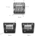
- the target identifiers are bow tie patterns 22, 24, 26 and 28 in the hologram 20.
- the target identifiers may be the points or nodes where lines in the pattern change direction.
- the relative location of the target identifiers appear to change in a predictive manner as the perspective of the viewer shifts.
- the bow tie 24 appears to be on the same plane as the logo 30, where the bow tie 22 appears to be forward of the plane of the logo 30, and the bow ties 26 and 28 appear to be at different depths behind the plane of the logo 30.
- the relative lengths of the vectors between any three of the target identifiers change.
- the apparent position of the target identifiers in a two-dimensional image of the hologram changes because of the parallax of the hologram.
- the hologram shown in Figure 1c is viewed from the same perspective as shown in Figure 1b and vectors between the bow tie target identifiers 22, 24 and 26 are shown. The lengths of these vectors and the ratio(s) of their lengths change in a predictable manner due to the full parallax of the hologram.
- still images of the master hologram are captured from numerous viewing angles and directions (i.e., viewing perspectives).
- still images of the master hologram can be generated at various distances from the hologram for each viewing perspective (i.e., viewing points).
- the viewing perspectives imaged cover a full range of viewing angles and directions from which the secondary hologram is likely to be observed during an authentication procedure.
- the master hologram is mounted into a viewing station equipped with a scanning device such as a camera or other video recorder.
- a viewing station is used to properly quantify and mark in space the coordinates of the original view perspective, and optional view point, of each image relative to the hologram.
- Perspectives can be described in angular coordinates or polar coordinates relative to the surface normal angle.
- Surface normal refers to a viewing angle that is directly perpendicular to the holographic surface at the center point of the hologram. At the surface normal the viewing perspective is said to be 0,0 and has no angular tilt in either direction. Subsequent shifts along the x-axis or y-axis would then be described by the resulting positive or negative angular rotation relative to the surface normal.
- Still images of the master hologram are captured from many known viewing perspectives.
- the view perspective relative to the surface normal of the hologram typically ranges from about -35 degrees to about +35 degrees in both axes, but can change depending on the intended angle of view characteristic of the specific master hologram.
- the captured images are digitally stored in a computer database along with the x, y (and optionally z) coordinates or the polar coordinates for each image.
- the number of images captured depends on the desired precision, but for a typical authentication process, at least about 1000 to 5000 images are recorded from a complete range of perspectives for use in the disclosed authentication process. Fewer captured images may require greater interpolation of intermediate identifier locations from surrounding images.
- At least two pairs of target identifiers are identified in each of the captured images.
- the identified target identifiers are in at least two depth planes in the hologram.
- the same target identifiers are identified and plotted in each image. This can be done manually, but it is preferably done by a scanning computer program that identifies the target identifiers in each of the digitally stored images.
- the scanning program may use feature recognition technology such as marker recognition or markerless recognition as used in the augmented reality (AR) and computer generated imagery (CGI) fields.
- the scanning computer program first crops the images to capture only the hologram in each image, and it then converts the image to greyscale.
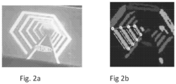
- the scanning program identifies the nodes where the lines of the hologram change direction as the target identifiers, and vectors linking the target identifiers A, B, C, D, A1, B1, C1, and D1 are generated as shown in Figure 2b , where the vectors are identified by the lines extending between the target identifier nodes.
- the scanning program records the x-y coordinates of each of the target identifiers /nodes and calculates the length of each of these linking vectors.
- the scanning program calculates the vector lengths and the comparative lengths of at least three of the vectors linking the target identifiers in each image taken from each view perspective.
- the vector length ratios are useful because they remain constant for a given view perspective (viewing angle and direction) regardless of the distance from the hologram at which the image was captured.
- the vectors between three target identifiers form what is known as a rigid body.
- the apparent length of the vectors of the rigid body change with the perspective from which the rigid body in the image exhibiting parallax is viewed.
- Vectors linking at least two pairs of target identifier nodes create a polygon.
- a single master image might have multiple polygons depending on the number of target identifiers and the desired precision.
- the vector length ratios are called a "triple" as there are three resulting vector length values. These triples are described by a ratio rather than absolute length in any given unit.
- a triangle with vector lengths measured in pixels might be 25px; 50px; 30px which has the same ratio as a triangle measured as 50px; 100px; 60px.
- the ratios of vector lengths change in a predictable manner with the view perspective (viewing angle and direction). This predictable change with viewing angle and direction makes it possible for the processor running the scanning computer program to next interpolate the vector length ratios for viewing angles and viewing directions from which images were not actually captured. Even though there isn't a captured image corresponding to each minute change in viewing angle and direction, these vector length ratio values can be accurately interpolated from data recorded from the scanned images.
- a horizontal (x-axis) polar perspective shift of +3 degrees from the surface normal resulted in a given vector increasing from 5 units to 7 units
- that vector length might be interpolated at 6 units for an assumed +1.5 degrees shift from normal along the same axis at equivalent distance.
- a digital model such as a computer database or mathematical model is generated from which the relative vector length ratios can be measured and/or interpolated for a complete set of possible hologram viewing angles and directions regardless of distance from the hologram.
- the authentication process also requires that the secondary hologram duplicates be generated from the master hologram or from a very high quality duplicate of the master hologram.
- the secondary holograms exhibit the same parallax as the master hologram.
- the processes for producing hologram duplicates are well established and known to those skilled in the art.
- the secondary hologram duplicates are affixed to or incorporated into products, documents or items that may require authentication.
- the secondary hologram duplicates can be associated with medicines, clothing and accessories, electronic devices, currency, passports and other government or non-governmental ID cards (academic, corporate), tickets, key cards, documents, and other items where authentication, brand protection, or anti-counterfeiting is necessary or desirable.
- the checker and/or checking device locates the secondary hologram.
- the checking device illuminates the secondary hologram with a point light source and a reconstruction of the hologram is generated and is captured by a camera, scanner, or other digital recorder of the checking device from an arbitrary viewing perspective. Where greater authentication accuracy is desired, multiple images may be captured.
- the scanning device is a smart phone or tablet computer equipped with a still or video camera and a flash emitter or other light source.
- the scanner is a portable digital scanning device that includes a digital scanner or camera and a point light source.
- the scanner is a digital camera mounted in a portable or table top device in conjunction with a point light source fixed at a known position relative to the scanner and connected to a computer to provide a rapid authentication response.
- the checking device may include a computer program or application that controls the camera and light source when the image of the secondary hologram is captured and that stores the captured image.
- the program or application may be one that is downloaded onto the checking device as a computer program or "app" from a website such as an App Store ® .
- the master hologram and/or the secondary hologram copies of the master hologram may contain other useful data detectable by a scanning device. Additional data may be fixed in the hologram as information, graphics, symbols, or schematics embedded in the holographic film. Codes (bar, QR, for example) can be used for automatic registrations for warranty, subscription, rebate, discount and other such purposes. Embedded codes or data can also be used for remote purchase verification such as for internet sales. The code may, for example, identify the hologram being authenticated or the internet address of a remote authentication processor so that when the scanned information is sent to the authentication processor, the scanned image will be compared against the data or digital model of the correct hologram.
- track-and-trace information that can be provided by a scanning device such as: point of sale, location of the product at any given time, demographic information about the buyer, the buyer's identity, contact information for the buyer, or whether the packaging or container for the product is being repurposed or recycled.
- Alerts for product upgrades and add-ons can be launched on the scanning device for the customer's information. These can help the supplier of the product in profiling target markets of potential interest. Assembly and use instructions, as well as demonstration or instructional videos, may auto-launch on the scanning device from codes or internet links embedded in the hologram.
- the scanning program records and saves the image and then electronically transmits the image to a remote processor computer that performs the functions of cropping the image, identifying the at least two pairs of target identifiers in the captured image, generating vectors between the identified target identifiers, measuring the lengths of the vectors and calculating the vector length ratios for the rigid body formed by the target identifiers, comparing the calculated vector length ratios with the ratios stored in the computer database generated from the master hologram or calculated from the digital model based on the master hologram, determining whether the difference between the ratios measured from the secondary hologram and the ratios from the master hologram computer database or digital model are below that required for the secondary hologram to be adjudicated authentic, and communicating the authentication adjudication back to a device proximate the authenticator or checking device, such as the authenticator's smart phone or a device associated with the checking device.
- a remote processor computer that performs the functions of cropping the image, identifying the at least two pairs of target identifiers
- the method of authentication compares vector length ratios of captured images of the reconstructed secondary hologram against the database of captured images of the master hologram from a known perspective.
- the scanning program calculates the perspective and/or view point from which the image was captured relative to the secondary hologram.
- the scanning program compares the vector length ratios in the scanned image against the vector length ratios for the corresponding perspective determined from the database or digital model generated from the master hologram.
- the viewing perspective of the image of the secondary hologram is determined through visual odometry techniques utilizing information proximate to or embedded in the hologram. For example, the hologram might be placed within a printed square bounding box of known proportion.
- this bounding box may be utilized to indicate the angle and direction (perspective) of the scanner as these qualities change in a predictable manner as the scanner angle and direction varies from the surface normal.
- the locations of target identifiers in the secondary hologram may be compared against a digital simulation model (for example, point cloud model) of the corresponding rigid bodies derived from the master hologram.
- the perspective of the scanner and scanned image is not known or determined. Instead, the scanner captures multiple images of the secondary hologram, locates target identifiers in each image, constructs three-sided polygons (triples), determines the vector length ratio of the triples, and verifies that the vector length ratio of each triple exists within an exhaustive master database, comprised of triples from images taken from a full range of perspectives. Each additional verifiable triple obtained from an image of a secondary hologram adds an increased level of certainty of the authentication.
- the process for identifying the at least two pairs of target identifiers in the captured image of the secondary hologram, creating vectors linking the target identifiers in the captured image of the secondary hologram, and determining the vector lengths and the comparative ratio(s) of the lengths of the vectors linking the target identifiers of the secondary hologram is the same process as described above for determining the vector length ratio(s) from the master hologram.
- the scanning program is located proximate where the secondary hologram is scanned and the scanning program performs the steps of cropping the image, identifying the target identifiers in the captured image, generating vectors between the identified target identifiers, measuring the lengths of the vectors and calculating the vector length ratio(s) for the rigid body formed by the target identifiers.
- the scanning program located proximate the scanner also calculates the perspective and/or view point from which the image was captured relative to the secondary hologram.
- the scanning device or a computer connected to the scanning device transmits the vector length ratio(s), and optionally the data identifying the view perspective or view point for the image, to a remote computer that performs the steps of comparing the vector length ratio(s) with the ratio(s) stored in a computer database generated from the master hologram or calculated from the digital model derived from the master hologram, determining whether the difference between the vector length ratio(s) measured from the secondary hologram and the vector length ratio(s) from the master hologram computer database or digital model are below that required for the secondary hologram to be judged authentic, and communicating the authentication adjudication back to a device proximate the scanning device and/or the authenticator.
- the scanning program located proximate where the secondary hologram is scanned performs the steps of cropping the image, identifying the target identifiers in the in the captured image, generating vectors between the identified target identifiers, measuring the lengths of the vectors and calculating the vector length ratio(s) for the rigid body formed by the target identifiers, comparing the vector length ratio(s) with the ratio(s) stored in a computer database generated from the master hologram or calculated from the digital model made from the master hologram that is stored on and executable from the scanning device or a computer proximate the scanning device, determining whether the difference between the ratio(s) measured from the secondary hologram and the ratio(s) from the master hologram computer database or digital model are below that required for the secondary hologram to be adjudicated authentic, and communicating the authentication adjudication to the checker.
- the scanning program may calculate the perspective and/or view point from which the image was captured relative to the secondary hologram and then compare the vector length ratio for only that perspective against the vector length ratio for the corresponding perspective in the computer database or digital model located proximate where the secondary hologram is scanned.
- the scanning program compares the vector length ratio against the vector length ratios for all perspectives in the database or digital model looking for any positive match.
- the scanning program located proximate where the secondary hologram is scanned performs the steps of capturing the images of the secondary hologram.
- the scanning device or a computer connected to the scanning device then transmits the images to a remote computer that performs all the tasks of identifying the target identifiers in the captured image, generating vectors between the identified target identifiers, measuring the lengths of the vectors and calculating the vector length ratio(s) for the rigid body formed by the target identifiers, comparing the vector length ratio(s) with the ratio(s) stored in a computer database generated from the master hologram or calculated from the digital model made from the master hologram, determining whether the difference between the vector length ratio(s) measured from the secondary hologram and the vector length ratio(s) from the master hologram computer database or digital model are below that required for the secondary hologram to be judged authentic, and communicating the authentication adjudication back to a location of the scanning device and/or the authenticator or another computer processor.
- the remote computer may calculate the perspective and/or view point from which the image was captured relative to the secondary hologram and then compare the vector length ratio for only that perspective against the vector length ratio for the corresponding perspective in the computer database or digital model located with the remote computer.
- the remote computer compares the vector length ratio against the vector length ratios for all perspectives in the database or digital model looking for any positive match.
- the authentication can be based on a single image of the secondary hologram, but the authentication system described can be made more robust by requiring a positive match on multiple scanned images of the secondary hologram before the secondary hologram is found to be authentic.
- determination of authentication is provided directly to the evaluator via the in-app user interface on, for example, a mobile smartphone.
- This communication might be transmitted by an on-screen graphic, vibration, sound, or any combination.
- the authentication determination can be communicated to an evaluator through various methods including, but not limited to, email, text message, SMS, phone call, facsimile, visual indicators on the scanning device, positive responses from a connected device such as a vending machine or electronic door latch, or other means of electronic communication.
- Figure 3 illustrates a block diagram of a parallax image validation system in accordance with one possible embodiment of the disclosure.
- the parallax image validation system 300 may include, for example, communication interface 310, a scanner 312, input and/or output devices 314 and 316, a point light source 318, a communications link 320, a computer database module and/or a digital computer model 322, a memory 324, a read only memory (ROM) 326, one or more processors 328, and an adjudication module 330.
- communication interface 310 may include, for example, communication interface 310, a scanner 312, input and/or output devices 314 and 316, a point light source 318, a communications link 320, a computer database module and/or a digital computer model 322, a memory 324, a read only memory (ROM) 326, one or more processors 328, and an adjudication module 330.
- ROM read only memory
- the communication interface 310 permits communication among the components of the parallax image validation system 300.
- the communication interface 310 may be a bus, a hard-wired connection, a wireless link, an optical connection, an audio connection, or any combination thereof.
- the communication interface 310 interconnects the other components of the system and allows the components to digitally communicate with each other.
- the communication interface may, for example, include a computer network, an ethernet connection, a cellular network connection, a wireless internet connection, an internet connection, or a combination thereof.
- Communication interface 310 may include any mechanism that facilitates communication via a network.
- the communication link 320 may include other mechanisms for assisting in communications with other devices and/or systems.
- the scanner 312 is an optical scanner such as a digital camera or recorder.
- Other possible scanning devices include a smart phone camera, printer, a copier, a document scanner, a multi-function printing and scanning device, a facsimile (fax) device, a personal computer, a portable computer, a notebook computer, a personal digital assistant, a tablet computer, a handheld scanner, a vending machine reader, a change machine reader, a currency reader/exchanger, an airport/train kiosk device, a ticket reading device, a gate or checkpoint reader, or other devices that may read documents or items with holograms.
- a smart phone camera is a preferred scanning device because much of the population already owns smart phones with cameras and light sources.
- Input device 314 may include one or more conventional mechanisms that permit a user to input information to the processing device, such as a keyboard, a touch screen or touch pad, a mouse, a digital pen, a voice recognition device, or a keypad.
- One or more than one input device may be incorporated into the validation system 300.
- Output device 316 may include one or more conventional mechanisms that output information to a user, including a display, a printer, a copier, a scanner, a multi-function device, one or more speakers, a display light or diode, or a medium, such as a memory, or a magnetic or optical disk and a corresponding disk drive.
- the point light source 318 may be a light bulb, a camera flash, a light or flash on a smart phone such as an LED light, sunlight, or another source of light.
- the light source is a light or flash on the scanning device that is controlled by the scanning device.
- Processor 328 may include at least one conventional processor or microprocessor that interprets and executes instructions.
- Memory 324 may be a random-access memory (RAM) or another type of dynamic storage device that stores information and instructions for execution by processor or processors 328.
- Read-only memory (ROM) 326 may also be included in the validation system 300 which may include a conventional ROM device or another type of static storage device that stores static information and instructions for processor 328.
- a storage device may augment the ROM and may include any type of storage media, such as, for example, a thumb drive, a hard drive, cloud drive, magnetic or optical recording media and its corresponding drive.
- the parallax image validation system 300 may perform such functions in response to processor 328 by executing sequences of instructions contained in a computer-readable medium, such as, for example, memory 324 and ROM 326. Such instructions may be read into memory 324 from another computer-readable medium, such as a storage device or from a separate device via the communication link 320, which for example could be a hard-wired connection, a wireless connection or an optical connection.
- a computer-readable medium such as, for example, memory 324 and ROM 326.
- Such instructions may be read into memory 324 from another computer-readable medium, such as a storage device or from a separate device via the communication link 320, which for example could be a hard-wired connection, a wireless connection or an optical connection.
- program modules include routine programs, objects, components, data structures, etc. that perform particular tasks or implement particular abstract data types.
- Computer-executable instructions include, for example, instructions and data which cause a general-purpose computer, special purpose computer, or special purpose processing device to perform a certain function or group of functions.
- Computer-executable instructions also include program modules that are executed by computers in stand-alone or network environments.
- program modules include routines, programs, objects, components, and data structures, and the like that perform particular tasks or implement particular abstract data types.
- Computer-executable instructions, associated data structures, and program modules represent examples of the program code means for executing steps of the methods disclosed herein.
- the particular sequence of such executable instructions or associated data structures represent examples of corresponding acts for implementing the functions described therein.
- a master hologram was produced by volume reflection holography using a glass plate coated with dichromated gelatin (DCG).
- Hologram A comprises three individual bow-tie targets resembling those depicted in Figure 1 .
- Hologram A exhibits full three-dimensional parallax.
- the first target was located at a depth plane coincident with the surface of the DCG emulsion; a condition commonly known in the art as being located on the film plane.
- a second bow-tie target was located on a parallel depth plane approximately 3 mm behind the film plane and the third target was located on a parallel depth plane approximately 2 mm in front of the film plane.
- This master hologram is designated as the "authentic master" version to be used in master database creation.
- Hologram A was placed in a viewing station and illuminated with a point light source in the form of a single white LED emitter located proximate a digital camera.
- the viewing station provided a mechanism whereby the camera could be positioned at various quantifiable perspectives within the intended angle of view of the hologram while remaining focused on the hologram and keeping the hologram centered in its field of view.
- a multiplicity of still images of Hologram A were captured and stored in a database. Each still image represented an individual polar coordinate relative to the surface normal designated as perspective (0,0). Still images were captured in successive one degree increments to the extent of reaching ⁇ 35 degrees in both the horizontal and vertical axes, and each image file was labelled with the appropriate perspective coordinate (e.g. -12,+6 corresponding to a perspective location that is minus 12° from normal in the horizontal axis, and +6° from normal in the vertical axis).
- perspective coordinate e.g. -12,+6 corresponding to a perspective location that is minus 12° from normal
- the master file was retrieved from the database corresponding to the perspective coordinates of another hologram that is to be compared to the master Hologram A.
- Master database images were cropped to include only the target identifiers and the cropped images were zoomed to aid in precision.
- a node was placed at the center of the bow- tie targets located at the junction point of the intersecting lines of each target. This node placement was performed manually with the aid of 2D CAD software. Alternatively the node placement could be performed digitally using common feature recognition techniques. Vectors were drawn between each pair of nodes creating a 3-sided polygon.
- Vector lengths were initially measured and measurements were converted to a ratio of relative lengths.
- the resulting ratio was therefore 1.00 : 1.61 : 0.82. This ratio remains constant regardless of the zoom extent of the cropped image.
- a duplicate Hologram B was created by directly replicating Hologram A using a contact copy method used in reflection holography replication.
- the replication process resulted in Hologram B being an exact replica of Hologram A with identical depth planes.
- Hologram B was placed in the viewing station and corresponding perspective angle of +15° y-axis and +5° x-axis was chosen.
- a still image was captured using a digital camera with a point light source. The image was cropped to include only the bow-tie targets and the cropped image was zoomed to aid in precision.
- a node was placed at the center of each of the bow-tie targets located at the junction point of the intersecting lines of each target.
- This node placement was performed manually with the help of 2D CAD software. Alternatively the node placement could be performed digitally using common feature recognition techniques.
- Vectors were drawn between each pair of nodes creating a 3-sided polygon. Vector lengths were initially measured and measurements were converted to a ratio of relative lengths. A three-sided polygon with side lengths 0.065532m (2.58 inch), 0.105664m (4.16inch), and 0.054102m (2.13inch) was the result of the measurement process, producing a triangle with side length ratio of 1.00 : 1.61 : 0.83 which is within the expected measurement error of the devices. The resulting ratio is deemed to be identical. Hologram B is deemed authentic.
- a third hologram was produced by volume reflection holography, using a glass plate coated with dichromated gelatin (DCG) comprised of three individual bow-tie targets resembling those depicted in Figure 1 .
- the first target was located at a depth plane coincident with the surface of the DCG emulsion.
- a second bow-tie target was located on a parallel depth plane approximately 2.5 mm behind the film plane and the third target was located on a parallel depth plane approximately 1.5 mm in front of the film plane.
- Hologram C was an attempted counterfeit of the master Hologram A and the two holograms appeared identical to the common unaided viewer.
- Hologram C was placed in the viewing station and a still image was captured from the perspective angle corresponding to +15° y-axis and +5° x-axis using a point light source.
- the image was cropped to include only the targets and the cropped image was zoomed to aid in precision.
- a node was placed at the center of the bow-tie targets located at the junction point of the intersecting lines of each target. This node placement was performed manually with the assistance of 2D CAD software. Alternatively the node placement could be performed digitally using common feature recognition techniques. Vectors were drawn between each pair of nodes creating a 3-sided polygon.
- the resulting vector lengths were 0.06604m (2.60 inch), 0.096012m (3.78inch), and 0.051054m (2.01 inch).
- the resulting side length ratio was therefore 1.00 : 1.45 : 0.77. Because the vector ratio from Hologram B did not precisely match the ratio for the corresponding master database image of Hologram A and was outside the error explainable by simple measurement error, Hologram C was deemed to be not authentic.
Claims (13)
- Procédé de détermination de la validité d'une image de parallaxe (20) comprenant :la réception d'une image bidimensionnelle saisie d'une image de parallaxe (20) possédant au minimum trois identifiants cibles (22, 24, 26, 28), au moins deux identifiants cibles étant situés à différents plans de profondeur dans l'image de parallaxe ;l'identification des au moins trois identifiants cibles dans l'image bidimensionnelle saisie de l'image de parallaxe, et la détermination de la relation spatiale entre les au minimum trois identifiants cibles dans l'image bidimensionnelle de l'image de parallaxe ;la comparaison de la relation spatiale des au moins trois identifiants cibles dans l'image bidimensionnelle saisie de l'image de parallaxe avec une relation spatiale prédéterminée des au moins trois identifiants cibles indiquant une authenticité ; etl'adjudication de l'authenticité de l'image de parallaxe en fonction du degré de différence entre la relation spatiale des au moins trois identifiants cibles dans l'image bidimensionnelle saisie de l'image de parallaxe et la relation spatiale prédéterminée des au moins trois identifiants cibles.
- Procédé selon la revendication 1, la relation spatiale des au moins trois identifiants cibles comprenant un rapport des longueurs des vecteurs reliant les identifiants cibles.
- Procédé selon la revendication 1 ou la revendication 2, comprenant en outre les étapes suivantes :saisie de multiples images bidimensionnelles d'une image de parallaxe principale prise de multiples perspectives ;identification d'au moins trois identifiants cibles dans chaque image bidimensionnelle saisie de l'image de parallaxe principale ;création d'une pluralité de vecteurs reliant les identifiants cibles dans chacune des images bidimensionnelles saisies de l'image de parallaxe principale ;détermination du rapport des longueurs des vecteurs reliant les identifiants cibles dans chacune des images bidimensionnelles saisies de l'image de parallaxe principale ; etgénération d'un modèle numérique pour l'image de parallaxe principale saisissant le rapport des longueurs des vecteurs reliant les identifiants cibles dans chacune des images bidimensionnelles saisies de l'image de parallaxe principale, le modèle numérique comprenant la relation spatiale prédéterminée, de préférence le procédé comprenant en outre :
la création d'une pluralité de vecteurs reliant les identifiants cibles dans l'image bidimensionnelle saisie de l'image de parallaxe ; et la détermination du rapport des longueurs des vecteurs reliant les identifiants cibles dans l'image bidimensionnelle saisie de l'image de parallaxe, et l'étape de comparaison comprenant :l'accès au modèle numérique pour l'image de parallaxe principale ; la comparaison du rapport de longueur vectoriel, déterminé d'après l'image bidimensionnelle saisie de l'image de parallaxe, avec des valeurs de rapport de longueur vectoriel saisies dans le modèle numérique pour l'image de parallaxe principale ; et le calcul de la différence entre le rapport de longueur vectoriel pour l'image bidimensionnelle saisie de l'image de parallaxe et les rapports de longueur vectoriels d'après le modèle numérique pour l'image de parallaxe principale ; etl'adjudication étant fonction du fait que la différence entre le rapport de longueur vectoriel d'après l'image bidimensionnelle saisie de l'image de parallaxe et le rapport de longueur vectoriel d'après le modèle numérique pour l'image de parallaxe principale est comprise dans une marge prédéterminée admissible. - Procédé selon la revendication 3, comprenant :la détermination de la perspective relative à l'image de parallaxe principale de chacune des multiples images bidimensionnelles de l'image de parallaxe principale ; et l'entrée des coordonnées de la perspective de chaque image bidimensionnelle de l'image de parallaxe principale dans le modèle numérique pour l'image de parallaxe principale et l'association de ces coordonnées de perspective au rapport des longueurs des vecteurs reliant les identifiants cibles dans chacune des images bidimensionnelles respectives de l'image de parallaxe principale saisie dans le modèle numérique pour l'image de parallaxe principale ;la détermination de la perspective relative à l'image de parallaxe de l'image bidimensionnelle saisie reçue de l'image de parallaxe ;la comparaison du rapport de longueur vectoriel déterminé d'après l'image bidimensionnelle saisie de l'image de parallaxe avec le rapport de longueur vectoriel saisi d'après le modèle numérique pour l'image de parallaxe principale pour substantiellement les mêmes coordonnées de perspective ; le calcul de la différence entre le rapport de longueur vectoriel pour l'image bidimensionnelle saisie de l'image de parallaxe et le rapport de longueur vectoriel correspondant du modèle numérique pour substantiellement les mêmes coordonnées de perspective ; et l'adjudication de l'authenticité de l'image bidimensionnelle saisie de l'image de parallaxe en fonction du fait que les différences entre le rapport de longueur vectoriel d'après l'image bidimensionnelle saisie de l'image de parallaxe et les valeurs de rapport de longueur vectoriel pour substantiellement les mêmes coordonnées de perspective sont comprises dans une marge prédéterminée admissible.
- Procédé selon une quelconque des revendications 3 à 4, comprenantla réception d'une pluralité d'images bidimensionnelles saisies d'une image de parallaxe ; l'identification d'au moins trois identifiants cibles dans chacune de la pluralité d'images bidimensionnelles saisies de l'image de parallaxe ; la création d'une pluralité de vecteurs reliant les identifiants cibles dans chacune de la pluralité d'images bidimensionnelles saisies de l'image de parallaxe ; et la détermination du rapport des longueurs des vecteurs reliant les identifiants cibles dans chacune de la pluralité d'images bidimensionnelles saisies de l'image de parallaxe ;l'accès au modèle numérique pour l'image de parallaxe principale ; la comparaison du rapport de longueur vectoriel déterminé d'après chacune de la pluralité d'images bidimensionnelles saisies de l'image de parallaxe avec les valeurs de rapport de longueur vectoriel saisies dans le modèle numérique pour l'image de parallaxe principale ; le calcul de la différence entre le rapport de longueur vectoriel pour chacune de la pluralité d'images bidimensionnelles saisies de l'image de parallaxe et les rapports de longueur vectoriels d'après le modèle numérique pour l'image de parallaxe principale ; et l'adjudication de l'authenticité de l'image bidimensionnelle saisie de l'image de parallaxe en fonction du fait que la différence entre le rapport de longueur vectoriel d'après chacune de la pluralité d'images bidimensionnelles saisies de l'image de parallaxe et le rapport de longueur vectoriel d'après le modèle numérique pour l'image de parallaxe principale est comprise dans une marge prédéterminée admissible.
- Procédé selon une quelconque des revendications précédentes, l'image de parallaxe étant une image présentant une parallaxe générée par un hologramme, l'image de parallaxe présentant de préférence une parallaxe complète, ou l'image de parallaxe étant une image lenticulaire ou une image de microlentille.
- Procédé selon une quelconque des revendications 2 à 6, l'image de parallaxe étant une image présentant une parallaxe générée d'après un hologramme, l'image de parallaxe présentant de préférence une parallaxe complète, ou l'image de parallaxe étant une image lenticulaire ou une image de microlentille.
- Procédé selon une quelconque des revendications précédentes, l'image de parallaxe étant pratiquée sur un document de valeur, comme un passeport, une carte d'identité, un permis de conduire, une carte bancaire, un billet de banque ou une étiquette de sécurité.
- Produit de programme informatique comprenant un ou plusieurs supports lisibles par ordinateur sur lequel figurent des instructions exécutables par ordinateur, qui, lorsqu'elles sont exécutées par un ou plusieurs processeurs d'un ordinateur, donnent lieu à l'exécution, par l'un ou plusieurs processeurs de l'ordinateur, du procédé selon une quelconque des revendications 1 à 8.
- Système d'authentification exécutable numériquement (300) pour la détermination de la validité d'une image de parallaxe, comprenant :un dispositif de balayage pour la réception d'une image bidimensionnelle saisie d'une image de parallaxe possédant au moins trois identifiants cibles, etun ou plusieurs processeurs (328) configurés pour exécuter le procédé selon une quelconque des revendications 1 à 8.
- Système d'authentification exécutable numériquement pour la détermination de la validité d'une image de parallaxe selon la revendication 10, l'image de parallaxe étant une image présentant une parallaxe générée par un hologramme, l'image de parallaxe présentant de préférence une parallaxe complète, ou l'image de parallaxe étant une image lenticulaire ou une image de microlentille.
- Procédé de validation d'un hologramme (20) présentant une parallaxe comprenant :la création d'un premier hologramme (20) présentant une parallaxe et contenant au moins trois identifiants cibles (22, 24, 26, 28), au moins deux desquels étant situés sur différents plans de profondeur ;la saisie d'images fixes du premier hologramme parmi de multiples perspectives de visualisation ;l'enregistrement des coordonnées de la perspective de visualisation de laquelle chaque image est saisie relativement au premier hologramme ;l'identification d'au moins deux paires d'identifiants cibles dans chacune des images saisies du premier hologramme ;la génération de vecteurs reliant les au moins deux paires d'identifiants cibles dans chaque image saisie du premier hologramme ;la détermination des rapports de longueur vectoriels relatifs des vecteurs générés reliant les identifiants cibles dans chaque image du premier hologramme ;l'enregistrement des rapports de longueur vectoriels pour chaque image ainsi que les coordonnées de la perspective de visualisation pour chaque image ;l'utilisation des rapports de longueur vectoriels enregistrés pour chaque image ainsi que les coordonnées d'image pour générer un premier modèle numérique holographique déterminant le rapport de longueur vectoriel pour un jeu complet de perspectives possibles desquelles le premier hologramme est visualisé ;la détermination du fait qu'un deuxième hologramme présentant une parallaxe est un double authentique du premier hologrammeen illuminant le deuxième hologramme avec une source lumineuse ponctuelle et en saisissant une image du deuxième hologramme illuminé ;en calculant les coordonnées de la perspective de visualisation de l'image saisie relativement au deuxième hologramme par une odométrie visuelle, en utilisant des informations proches du deuxième hologramme ou intégrées dans celui-ci ;en identifiant les au moins deux paires d'identifiants cibles identifiées dans le premier hologramme dans l'image saisie du deuxième hologramme ;en créant des vecteurs reliant les identifiants cibles dans l'image saisie du deuxième hologramme, et en déterminant le rapport des longueurs des vecteurs reliant les identifiants cibles dans le deuxième hologramme,en calculant la différence entre le rapport de longueur vectoriel d'après le deuxième hologramme et le rapport de longueur vectoriel correspondant déterminé d'après le premier modèle numérique holographique pour les coordonnées de perspective d'après lesquelles l'image du deuxième hologramme a été saisie ;en adjugeant l'authenticité du deuxième hologramme selon que la différence entre le rapport de longueur vectoriel d'après l'image saisie du deuxième hologramme et les valeurs de rapport de longueur vectoriel correspondantes d'après le modèle numérique du premier hologramme est comprise dans une marge prédéterminée admissible ; eten communiquant la détermination de l'authentification à un évaluateur du deuxième hologramme.
- Procédé de validation d'un hologramme présentant une parallaxe selon la revendication 12, la saisie d'une image du deuxième hologramme illuminé étant effectuée à l'aide d'un dispositif de balayage (312) sélectionné parmi des caméras, des scanners et des enregistreurs numériques, le dispositif de balayage étant de préférence un téléphone intelligent équipé avec un appareil photo et une source lumineuse ponctuelle.
Applications Claiming Priority (2)
| Application Number | Priority Date | Filing Date | Title |
|---|---|---|---|
| US201662296316P | 2016-02-17 | 2016-02-17 | |
| PCT/IB2017/050872 WO2017141184A1 (fr) | 2016-02-17 | 2017-02-16 | Procédé de détermination d'authenticité à l'aide d'images présentant une parallaxe |
Publications (3)
| Publication Number | Publication Date |
|---|---|
| EP3417428A1 EP3417428A1 (fr) | 2018-12-26 |
| EP3417428B1 true EP3417428B1 (fr) | 2023-06-07 |
| EP3417428C0 EP3417428C0 (fr) | 2023-06-07 |
Family
ID=58228357
Family Applications (1)
| Application Number | Title | Priority Date | Filing Date |
|---|---|---|---|
| EP17708884.6A Active EP3417428B1 (fr) | 2016-02-17 | 2017-02-16 | Procédé de détermination d'authenticité à l'aide d'images présentant une parallaxe |
Country Status (3)
| Country | Link |
|---|---|
| US (2) | US11409239B2 (fr) |
| EP (1) | EP3417428B1 (fr) |
| WO (1) | WO2017141184A1 (fr) |
Families Citing this family (4)
| Publication number | Priority date | Publication date | Assignee | Title |
|---|---|---|---|---|
| EP3407559A1 (fr) * | 2017-05-26 | 2018-11-28 | Authentic Vision GmbH | Système et procédé de gestion de privilèges basé sur l'authentification d'un dispositif de sécurité non clonable |
| FR3076924A3 (fr) | 2018-01-16 | 2019-07-19 | Franck Guigan | Procede d’authentification d’une signature tridimensionnelle |
| US11961294B2 (en) * | 2019-09-09 | 2024-04-16 | Techinvest Company Limited | Augmented, virtual and mixed-reality content selection and display |
| FR3130059A1 (fr) * | 2021-12-07 | 2023-06-09 | Idemia France | Procédé d’authentification d’un document d’identité, et dispositif pour mettre en œuvre le procédé |
Citations (1)
| Publication number | Priority date | Publication date | Assignee | Title |
|---|---|---|---|---|
| EP1852752A2 (fr) * | 2006-04-28 | 2007-11-07 | Kabushiki Kaisha Toshiba | Appareil de vérification et procédé de vérification pour support d'enregistrement |
Family Cites Families (11)
| Publication number | Priority date | Publication date | Assignee | Title |
|---|---|---|---|---|
| DE4131964A1 (de) | 1991-09-25 | 1993-04-08 | Holtronic Gmbh | Verfahren zur beschriftung oder kennzeichnung von hologrammen |
| US6608911B2 (en) * | 2000-12-21 | 2003-08-19 | Digimarc Corporation | Digitally watermaking holograms for use with smart cards |
| GB0016356D0 (en) * | 2000-07-03 | 2000-08-23 | Optaglio Ltd | Optical structure |
| JP4560941B2 (ja) | 2000-10-25 | 2010-10-13 | 凸版印刷株式会社 | ホログラムの真偽判定方法 |
| US6782116B1 (en) * | 2002-11-04 | 2004-08-24 | Mediasec Technologies, Gmbh | Apparatus and methods for improving detection of watermarks in content that has undergone a lossy transformation |
| US8928654B2 (en) * | 2004-07-30 | 2015-01-06 | Extreme Reality Ltd. | Methods, systems, devices and associated processing logic for generating stereoscopic images and video |
| EP2695147B1 (fr) | 2011-04-05 | 2019-03-06 | Franck Guigan | Code-barres de sécurité |
| EP2863827B1 (fr) * | 2012-06-21 | 2022-11-16 | Globus Medical, Inc. | Plateforme de robot chirurgical |
| CH708368A1 (de) * | 2013-07-25 | 2015-01-30 | Unica Technology Ag | Verfahren und Gerät zur Verifikation von diffraktiven Elementen. |
| FR3053501B1 (fr) | 2016-06-29 | 2018-11-09 | Safran Identity & Security | Procede d'authentification de documents au moyen d'un terminal mobile de telecommunication |
| US10083353B2 (en) * | 2016-10-28 | 2018-09-25 | Intuit Inc. | Identifying document forms using digital fingerprints |
-
2017
- 2017-02-16 WO PCT/IB2017/050872 patent/WO2017141184A1/fr active Application Filing
- 2017-02-16 EP EP17708884.6A patent/EP3417428B1/fr active Active
- 2017-02-16 US US15/998,926 patent/US11409239B2/en active Active
-
2022
- 2022-07-05 US US17/857,641 patent/US20220334535A1/en active Pending
Patent Citations (1)
| Publication number | Priority date | Publication date | Assignee | Title |
|---|---|---|---|---|
| EP1852752A2 (fr) * | 2006-04-28 | 2007-11-07 | Kabushiki Kaisha Toshiba | Appareil de vérification et procédé de vérification pour support d'enregistrement |
Also Published As
| Publication number | Publication date |
|---|---|
| EP3417428A1 (fr) | 2018-12-26 |
| US20220334535A1 (en) | 2022-10-20 |
| US11409239B2 (en) | 2022-08-09 |
| EP3417428C0 (fr) | 2023-06-07 |
| US20190258204A1 (en) | 2019-08-22 |
| WO2017141184A1 (fr) | 2017-08-24 |
Similar Documents
| Publication | Publication Date | Title |
|---|---|---|
| US20220334535A1 (en) | Method for determining authenticity using images that exhibit parallax | |
| US9817367B2 (en) | Method and device for verifying diffractive elements | |
| CN1661627B (zh) | 具有随机出现特征的防假冒和防篡改标签的方法和系统 | |
| US9224241B2 (en) | System for producing digital holographic content | |
| US8072626B2 (en) | System for reading and authenticating a composite image in a sheeting | |
| US20150369593A1 (en) | Orthographic image capture system | |
| EA025922B1 (ru) | Способ автоматической аутентификации защищенного документа | |
| CN106408063B (zh) | 打印介质及其生成方法和扫描方法和标签 | |
| CN109472337B (zh) | 一种基于随机特征的标签防伪方法和装置 | |
| TWM519760U (zh) | 具有機器可讀圖像之卡 | |
| WO2020157567A1 (fr) | Authentification et suivi par codes cachés | |
| US20230074616A1 (en) | Systems, methods and devices to Administer a Security Device with Chaosmetric Patterns | |
| WO2015075726A1 (fr) | Procédé et appareil d'authentification d'un élément par codage et décodage de signaux dépendant de la position | |
| EP1647415A2 (fr) | Support d'enregistrement holographique de type surface en relief et système optique de lecture le même | |
| CN110245733A (zh) | 物品验证方法 | |
| KR20200116829A (ko) | 입체인쇄 스티커의 정품 인증 장치 및 시스템 | |
| WO2023214546A1 (fr) | Programme informatique, dispositif de détermination d'authenticité et procédé de détermination d'authenticité | |
| EP4138053A1 (fr) | Structure d'authentification optique avec fonctionnalité de réalité augmentée | |
| CN109272078A (zh) | 一种身份认证系统和方法 | |
| WO2024069159A1 (fr) | Jeton d'authentification d'un produit | |
| US11853408B2 (en) | Authentication of a physical credential | |
| CN114154604A (zh) | 一种附带光栅的图形码装置及对其扫描方法 | |
| JP3840109B2 (ja) | 画像処理装置 | |
| Siegmund et al. | Deep learning for occlusion aware RGB-D image completion for structured light measurements | |
| WO2022197578A1 (fr) | Systèmes, procédés et dispositifs pour administrer un dispositif de sécurité à motifs chaosmétriques |
Legal Events
| Date | Code | Title | Description |
|---|---|---|---|
| STAA | Information on the status of an ep patent application or granted ep patent |
Free format text: STATUS: UNKNOWN |
|
| STAA | Information on the status of an ep patent application or granted ep patent |
Free format text: STATUS: THE INTERNATIONAL PUBLICATION HAS BEEN MADE |
|
| PUAI | Public reference made under article 153(3) epc to a published international application that has entered the european phase |
Free format text: ORIGINAL CODE: 0009012 |
|
| STAA | Information on the status of an ep patent application or granted ep patent |
Free format text: STATUS: REQUEST FOR EXAMINATION WAS MADE |
|
| 17P | Request for examination filed |
Effective date: 20180830 |
|
| AK | Designated contracting states |
Kind code of ref document: A1 Designated state(s): AL AT BE BG CH CY CZ DE DK EE ES FI FR GB GR HR HU IE IS IT LI LT LU LV MC MK MT NL NO PL PT RO RS SE SI SK SM TR |
|
| AX | Request for extension of the european patent |
Extension state: BA ME |
|
| RIN1 | Information on inventor provided before grant (corrected) |
Inventor name: NELSON, BRETT RONALD |
|
| DAV | Request for validation of the european patent (deleted) | ||
| DAX | Request for extension of the european patent (deleted) | ||
| STAA | Information on the status of an ep patent application or granted ep patent |
Free format text: STATUS: EXAMINATION IS IN PROGRESS |
|
| 17Q | First examination report despatched |
Effective date: 20190919 |
|
| STAA | Information on the status of an ep patent application or granted ep patent |
Free format text: STATUS: EXAMINATION IS IN PROGRESS |
|
| STAA | Information on the status of an ep patent application or granted ep patent |
Free format text: STATUS: EXAMINATION IS IN PROGRESS |
|
| GRAP | Despatch of communication of intention to grant a patent |
Free format text: ORIGINAL CODE: EPIDOSNIGR1 |
|
| STAA | Information on the status of an ep patent application or granted ep patent |
Free format text: STATUS: GRANT OF PATENT IS INTENDED |
|
| INTG | Intention to grant announced |
Effective date: 20220531 |
|
| GRAJ | Information related to disapproval of communication of intention to grant by the applicant or resumption of examination proceedings by the epo deleted |
Free format text: ORIGINAL CODE: EPIDOSDIGR1 |
|
| STAA | Information on the status of an ep patent application or granted ep patent |
Free format text: STATUS: EXAMINATION IS IN PROGRESS |
|
| GRAP | Despatch of communication of intention to grant a patent |
Free format text: ORIGINAL CODE: EPIDOSNIGR1 |
|
| STAA | Information on the status of an ep patent application or granted ep patent |
Free format text: STATUS: GRANT OF PATENT IS INTENDED |
|
| INTC | Intention to grant announced (deleted) | ||
| INTG | Intention to grant announced |
Effective date: 20221109 |
|
| GRAS | Grant fee paid |
Free format text: ORIGINAL CODE: EPIDOSNIGR3 |
|
| GRAA | (expected) grant |
Free format text: ORIGINAL CODE: 0009210 |
|
| STAA | Information on the status of an ep patent application or granted ep patent |
Free format text: STATUS: THE PATENT HAS BEEN GRANTED |
|
| AK | Designated contracting states |
Kind code of ref document: B1 Designated state(s): AL AT BE BG CH CY CZ DE DK EE ES FI FR GB GR HR HU IE IS IT LI LT LU LV MC MK MT NL NO PL PT RO RS SE SI SK SM TR |
|
| REG | Reference to a national code |
Ref country code: GB Ref legal event code: FG4D |
|
| REG | Reference to a national code |
Ref country code: CH Ref legal event code: EP Ref country code: AT Ref legal event code: REF Ref document number: 1577319 Country of ref document: AT Kind code of ref document: T Effective date: 20230615 Ref country code: DE Ref legal event code: R096 Ref document number: 602017069459 Country of ref document: DE |
|
| U01 | Request for unitary effect filed |
Effective date: 20230616 |
|
| U07 | Unitary effect registered |
Designated state(s): AT BE BG DE DK EE FI FR IT LT LU LV MT NL PT SE SI Effective date: 20230626 |
|
| REG | Reference to a national code |
Ref country code: LT Ref legal event code: MG9D |
|
| PG25 | Lapsed in a contracting state [announced via postgrant information from national office to epo] |
Ref country code: NO Free format text: LAPSE BECAUSE OF FAILURE TO SUBMIT A TRANSLATION OF THE DESCRIPTION OR TO PAY THE FEE WITHIN THE PRESCRIBED TIME-LIMIT Effective date: 20230907 Ref country code: ES Free format text: LAPSE BECAUSE OF FAILURE TO SUBMIT A TRANSLATION OF THE DESCRIPTION OR TO PAY THE FEE WITHIN THE PRESCRIBED TIME-LIMIT Effective date: 20230607 |
|
| PG25 | Lapsed in a contracting state [announced via postgrant information from national office to epo] |
Ref country code: RS Free format text: LAPSE BECAUSE OF FAILURE TO SUBMIT A TRANSLATION OF THE DESCRIPTION OR TO PAY THE FEE WITHIN THE PRESCRIBED TIME-LIMIT Effective date: 20230607 Ref country code: HR Free format text: LAPSE BECAUSE OF FAILURE TO SUBMIT A TRANSLATION OF THE DESCRIPTION OR TO PAY THE FEE WITHIN THE PRESCRIBED TIME-LIMIT Effective date: 20230607 Ref country code: GR Free format text: LAPSE BECAUSE OF FAILURE TO SUBMIT A TRANSLATION OF THE DESCRIPTION OR TO PAY THE FEE WITHIN THE PRESCRIBED TIME-LIMIT Effective date: 20230908 |
|
| PG25 | Lapsed in a contracting state [announced via postgrant information from national office to epo] |
Ref country code: SK Free format text: LAPSE BECAUSE OF FAILURE TO SUBMIT A TRANSLATION OF THE DESCRIPTION OR TO PAY THE FEE WITHIN THE PRESCRIBED TIME-LIMIT Effective date: 20230607 |
|
| PG25 | Lapsed in a contracting state [announced via postgrant information from national office to epo] |
Ref country code: IS Free format text: LAPSE BECAUSE OF FAILURE TO SUBMIT A TRANSLATION OF THE DESCRIPTION OR TO PAY THE FEE WITHIN THE PRESCRIBED TIME-LIMIT Effective date: 20231007 |
|
| PG25 | Lapsed in a contracting state [announced via postgrant information from national office to epo] |
Ref country code: SM Free format text: LAPSE BECAUSE OF FAILURE TO SUBMIT A TRANSLATION OF THE DESCRIPTION OR TO PAY THE FEE WITHIN THE PRESCRIBED TIME-LIMIT Effective date: 20230607 Ref country code: SK Free format text: LAPSE BECAUSE OF FAILURE TO SUBMIT A TRANSLATION OF THE DESCRIPTION OR TO PAY THE FEE WITHIN THE PRESCRIBED TIME-LIMIT Effective date: 20230607 Ref country code: RO Free format text: LAPSE BECAUSE OF FAILURE TO SUBMIT A TRANSLATION OF THE DESCRIPTION OR TO PAY THE FEE WITHIN THE PRESCRIBED TIME-LIMIT Effective date: 20230607 Ref country code: IS Free format text: LAPSE BECAUSE OF FAILURE TO SUBMIT A TRANSLATION OF THE DESCRIPTION OR TO PAY THE FEE WITHIN THE PRESCRIBED TIME-LIMIT Effective date: 20231007 Ref country code: CZ Free format text: LAPSE BECAUSE OF FAILURE TO SUBMIT A TRANSLATION OF THE DESCRIPTION OR TO PAY THE FEE WITHIN THE PRESCRIBED TIME-LIMIT Effective date: 20230607 |
|
| U20 | Renewal fee paid [unitary effect] |
Year of fee payment: 8 Effective date: 20240108 |
|
| PG25 | Lapsed in a contracting state [announced via postgrant information from national office to epo] |
Ref country code: PL Free format text: LAPSE BECAUSE OF FAILURE TO SUBMIT A TRANSLATION OF THE DESCRIPTION OR TO PAY THE FEE WITHIN THE PRESCRIBED TIME-LIMIT Effective date: 20230607 |
|
| PLBE | No opposition filed within time limit |
Free format text: ORIGINAL CODE: 0009261 |
|
| STAA | Information on the status of an ep patent application or granted ep patent |
Free format text: STATUS: NO OPPOSITION FILED WITHIN TIME LIMIT |