EP3417233B1 - Initiateur opto-pyrotechnique - Google Patents
Initiateur opto-pyrotechnique Download PDFInfo
- Publication number
- EP3417233B1 EP3417233B1 EP17709154.3A EP17709154A EP3417233B1 EP 3417233 B1 EP3417233 B1 EP 3417233B1 EP 17709154 A EP17709154 A EP 17709154A EP 3417233 B1 EP3417233 B1 EP 3417233B1
- Authority
- EP
- European Patent Office
- Prior art keywords
- optical fiber
- inlet
- glass
- initiator
- pyrotechnic
- Prior art date
- Legal status (The legal status is an assumption and is not a legal conclusion. Google has not performed a legal analysis and makes no representation as to the accuracy of the status listed.)
- Active
Links
Images

Classifications
-
- F—MECHANICAL ENGINEERING; LIGHTING; HEATING; WEAPONS; BLASTING
- F42—AMMUNITION; BLASTING
- F42B—EXPLOSIVE CHARGES, e.g. FOR BLASTING, FIREWORKS, AMMUNITION
- F42B3/00—Blasting cartridges, i.e. case and explosive
- F42B3/10—Initiators therefor
- F42B3/113—Initiators therefor activated by optical means, e.g. laser, flashlight
-
- F—MECHANICAL ENGINEERING; LIGHTING; HEATING; WEAPONS; BLASTING
- F42—AMMUNITION; BLASTING
- F42B—EXPLOSIVE CHARGES, e.g. FOR BLASTING, FIREWORKS, AMMUNITION
- F42B3/00—Blasting cartridges, i.e. case and explosive
- F42B3/10—Initiators therefor
- F42B3/195—Manufacture
-
- F—MECHANICAL ENGINEERING; LIGHTING; HEATING; WEAPONS; BLASTING
- F42—AMMUNITION; BLASTING
- F42C—AMMUNITION FUZES; ARMING OR SAFETY MEANS THEREFOR
- F42C19/00—Details of fuzes
- F42C19/08—Primers; Detonators
Definitions
- the invention relates to the field of pyrotechnic initiators whose ignition or priming is carried out by means of a light energy signal.
- This type of initiator is called an opto-pyrotechnic initiator.
- the invention relates particularly but not exclusively to applications in space launch vehicles where opto-pyrotechnic initiators are used to perform numerous pyrotechnic functions.
- FR 3 006 433 A1 discloses an opto-pyrotechnic initiator and a method of manufacturing an opto-pyrotechnic initiator.
- an opto-pyrotechnic initiator comprises a pyrotechnic charge disposed in a cavity, an optical fiber connected by a first end to a source of light radiation, for example a laser diode, the other end of the optical fiber being placed at near the pyrotechnic charge in order to transmit the light radiation to it and switch it on.
- a source of light radiation for example a laser diode
- connection between the optical fiber and the body of the initiator is generally carried out by bonding the fiber in a ferrule with a seal or directly on the body.
- This type of connection has several drawbacks, in particular when the initiator is intended to be exposed to high temperatures and pressures. Indeed, an optical fiber / initiator body connection made by means of an adhesive has a limited lifespan due to the degassing of the organic products present in the connection which degrade over time. In addition, the mechanical and / or thermal resistance of this type of connection is no longer ensured under conditions of temperatures of several hundred degrees and pressures of several hundred megapascals. Furthermore, this type of connection is complex and expensive to implement, in particular because of the need to use several elements (ferrule, joint) to make the connection.
- the method of manufacturing an opto-pyrotechnic initiator of the invention is in particular advantageous in that it makes it possible to form a connection between the optical fiber and the body of the initiator by sealing with glass.
- the optical fiber is sealed on the body of the initiator by a hermetic glass sealing element which ensures perfect adhesion both with the body of the initiator and the optical fiber and, therefore, a perfect seal.
- a sealing element is able to withstand temperatures of more than 2700 ° C over very short periods (a few milliseconds), temperatures of the order of 200 ° C over longer periods (several minutes) and pressures of several hundred megapascals (MPa) corresponding to the conditions of use encountered in space launch vehicles.
- connection between the optical fiber and the body of the initiator produced in accordance with the process of the invention is devoid of organic products, which is not the case with the connections of the prior art which use elastomer seals and glue in large quantities for structural strength.
- the connection according to the invention is also chemically compatible with the optical fiber. It also allows reduce the number of parts required to make a sealed connection while being economical to produce and easy to industrialize.
- the glass preform has a melting point between 320 ° C and 350 ° C, which preserves the integrity of the fiber.
- the glass preform is heated until reaching a peak temperature of between 320 ° C. and 420 ° C., the heating time, once the peak temperature reached, being between 1 and 15 seconds.
- the method of the invention further comprises a step of removing the organic coating present around the optical fiber at the level of the first portion of said fiber. This makes it possible to increase the adhesion power between the sealing element and the optical fiber while avoiding degassing on the surface of the fiber during the heat treatment.
- the body of the initiator can be made of refractory ceramic material or metallic material.
- the glass preform is produced by pressing a glass powder and sintering the powder into a determined form.
- the sintering does not leave any residue in the preform thus formed so that, when the glass is melted, there is no degassing.
- the glass preform has an annular shape, which facilitates its interposition between the optical fiber and the entry of the body of the initiator.
- the present invention also relates to an opto-pyrotechnic initiator comprising a body comprising a cavity in which is housed a pyrotechnic charge, the body further comprising an internal passage extending between an inlet opening on an external face of said body and the cavity containing the pyrotechnic charge, an optical fiber comprising a first portion present in the internal passage of the body and a second portion present outside the body, the optical fiber being intended to convey a light signal capable of initiating the pyrotechnic charge, the initiator further comprising a glass sealing element present between the inlet of the body and the fiber optical, the sealing element adhering both to the wall of the body entrance and to the external surface of the optical fiber.
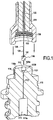
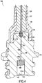
- the figures 1 to 4 show the manufacture of an opto-pyrotechnic initiator in accordance with an embodiment of the invention.
- the method begins with the formation of a body 110 comprising a cavity 111 in which is intended to be housed a charge or pyrotechnic composition.
- the cavity 111 comprises an opening 111a located in the lower part of the body 110, the opening 111a corresponding to the part of the body 110 through which the gases generated by the pyrotechnic charge are discharged.
- the body 110 also comprises an internal passage 112 extending between an inlet 113 opening onto the upper external face 110a of the body 110 and the cavity 111.
- the inlet 113 here comprises a cavity 1130 having a section (diameter) greater than that from the internal passage 112, the cavity 1130 being connected to the internal passage 112 by a neck 1131 having a decreasing section from the cavity 1130 to the internal passage 112.
- the body 110 can be formed from a metallic material such as Inconel, 316L or 17-4 PH stainless steel or a refractory ceramic material such as, for example, alumina, aluminum nitride or boron nitride.
- the manufacture of the opto-pyrotechnic initiator continues with the placement of an optical fiber 120 in the body 110.
- the optical fiber 120 comprises a first portion 121 intended to be placed in the internal passage 112 so that that the end 120a of the optical fiber 120 is positioned as close as possible and facing a pyrotechnic charge 105 ( figure 4 ).
- the optical fiber 120 comprises a second portion 122 which extends beyond the inlet 113 of the body 110.
- the second portion 122 is supported in an end piece 130 comprising a sheath 131 to protect the optical fiber 120.
- the end piece 130 here has a thread 132 intended to cooperate with a thread 114 present on the body 110 so as to facilitate the connection of the end piece 130 with the body 110.
- the end of the optical fiber 120 (not shown in the figures) opposite to the end 120a is intended to be connected to a source of optical energy such as for example a laser diode.
- the first portion 121 of the optical fiber 120 is stripped before being placed in the internal passage 112. This step may include the elimination of the protective sheath possibly present around the fiber and the elimination of the organic coating present on the external surface. of fiber in order to promote adhesion with the glass of the preform during its melting.
- a glass preform 140 is interposed between the optical fiber and the inlet 113 of the body 110.
- the preform 140 has an annular shape , the optical fiber 120 being housed in the central opening 141 of the preform 140.
- the preform 140 has a diameter less than that of the cavity 1130 of the inlet 113 so as to be able to be arranged in this one as illustrated on the figure 2 .
- the preform 140 may in particular be formed by pressing in the form of a glass powder and sintering the powder into a determined form such as for example an annular form. Sintering has the advantage of not leaving residues so that, during reflow, there is no degassing, making it possible to produce a perfectly sealed connection.
- the first portion 121 of the optical fiber 120 is then positioned in the internal passage 112 while the glass preform 140 is present in the cavity 1130 of the inlet 113 of the body 110.
- the preform 140 is then heat treated at a temperature above the melting point thereof so as to form a hermetic sealing element 150 between the optical fiber 120 and the inlet 113 of the body 110 ( figure 4 ).
- the glass preform 140 is produced from a glass composition having a melting point lower than that of the optical fiber so as not to expose the optical fiber to excessively high temperatures liable to damage it.
- a glass composition doped with one or more elements is used for this purpose, making it possible to lower the melting point of the composition to a temperature below the melting temperature of the optical fiber.
- the glass composition used to form the preform can in particular be a glass composition doped with lead, phosphate or bismuth.
- the glass preform 140 thus preferably has a melting point or temperature between 320 ° C and 350 ° C, temperatures significantly lower than the melting temperature of most optical fibers. Heating of the preform until it melts is preferably carried out locally at the level of the body 110, that is to say at the level of the zone comprising the preform, with a rapid rise in temperature to a peak temperature. determined as a function of the melting point of the preform 140.
- the peak temperature is preferably between 320 ° C and 420 ° C, this being preferably maintained over a period of between 1 and 15 seconds.
- the preform can be fused in particular with one of the following heating means: electric heating, infrared radiation, induction heating, hot air, laser and conduction heating.
- the figure 3 illustrates the fusion of preform 140.
- the preform of molten glass spreads in the cavity 1130 but also in the neck 1131, which makes it possible to increase the surface of adhesion with the optical fiber while allowing the expansion of the glass with a minimum of constraints.
- the heating is stopped to allow the glass to cool and harden.
- a pyrotechnic charge 105 is then placed, for example by compaction, in the cavity 111 which is then optionally closed with a cover 115.
- an opto-pyrotechnic initiator 100 comprising a body 110 comprising a cavity 111 in which is housed a pyrotechnic charge 105, the body 110 further comprising an internal passage 112 extending between an inlet 113 opening onto an external face of said body and the cavity 111.
- the initiator 100 also comprises an optical fiber 120 with a first portion 121 present in the internal passage 112 of the body 110 and a second portion 122 present outside of the body 110, the end 120a of the optical fiber being in as close as possible, even in contact, with the pyrotechnic charge 105.
- the opto-pyrotechnic initiator 100 further comprises a hermetic glass sealing element 150 present between the inlet 113 of the body 110 and the optical fiber 120, the sealing element 150 adhering both to the wall of the inlet 113 and to the external surface of the optical fiber 120.
- the optical fiber 120 is intended to convey a light signal capable of initiating the pyrotechnic charge 105.
- the opto-pyrotechnic initiator of the invention can be used to form a pyrotechnic chain, the body of the initiator then forming the first stage of the chain, the other stages of the pyrotechnic chain comprising pyrotechnic charges less and less sensitive and more and more energy than the charge of the initiator.
- the opto-pyrotechnic initiator of the invention is intended to be used in harsh environments in particular in terms of pressure and temperature. Indeed, the opto-pyrotechnic initiator of the invention must be able to withstand thermal flashes of a few milliseconds at temperatures above 2700 ° C as well as temperatures of the order of 200 ° C over a period of several minutes . It must also be able to withstand dynamic pressures of several hundred megapascals (MPa).
- MPa megapascals
- the opto-pyrotechnic initiator of the invention is able to withstand such conditions of use in particular thanks to the connection between the optical fiber and the body of the initiator which is produced by a hermetic sealing element made of glass. Indeed, the sealing element being made of glass, it adheres perfectly both with the body of the initiator, whether this is made of metallic or ceramic material, and with the optical fiber itself made of glass.
Landscapes
- Engineering & Computer Science (AREA)
- General Engineering & Computer Science (AREA)
- Physics & Mathematics (AREA)
- Optics & Photonics (AREA)
- Manufacturing & Machinery (AREA)
- Optical Couplings Of Light Guides (AREA)
Description
- L'invention concerne le domaine des initiateurs pyrotechnique dont l'allumage ou l'amorçage est réalisé au moyen d'un signal d'énergie lumineuse. Ce type d'initiateur est appelé initiateur opto-pyrotechnique. L'invention concerne particulièrement mais non exclusivement des applications dans les lanceurs spatiaux où des initiateurs opto-pyrotechniques sont utilisés pour réaliser de nombreuses fonctions pyrotechniques.
FR 3 006 433 A1 - De manière connue, un initiateur opto-pyrotechnique comprend une charge pyrotechnique disposée dans une cavité, une fibre optique raccordée par une première extrémité à une source de rayonnement lumineux, par exemple une diode laser, l'autre extrémité de la fibre optique étant placée à proximité de la charge pyrotechnique afin de lui transmettre le rayonnement lumineux et allumer cette dernière.
- La liaison entre la fibre optique et le corps de l'initiateur est en général réalisée par collage de la fibre dans une férule avec un joint ou directement sur le corps. Ce type de liaison présente plusieurs inconvénients, en particulier lorsque l'initiateur est destiné à être exposé à des températures et des pressions importantes. En effet, une liaison fibre optique/corps initiateur réalisée au moyen d'un adhésif possède une durée de vie limitée en raison des dégazages des produits organiques présents dans la liaison qui se dégradent dans le temps. En outre, la tenue mécanique et/ou thermique de ce type de liaison n'est plus assurée dans des conditions de températures de plusieurs centaines de degrés et de pressions de plusieurs centaines de mégapascals,. Par ailleurs, ce type de liaison est complexe et onéreux à mettre en œuvre en raison notamment de la nécessité d'utiliser plusieurs éléments (férule, joint) pour réaliser la liaison.
- Or, il existe un besoin pour un initiateur opto-pyrotechnique apte à supporter et fonctionner dans des conditions sévères de températures et de pressions, et ce avec des durées de vie longues tout en étant fabricable de manière industrielle.
- A cet effet, la présente invention propose un procédé de fabrication d'un initiateur opto-pyrotechnique comprenant les étapes suivantes :
- a) la formation d'un corps comportant une cavité dans laquelle une charge pyrotechnique est destinée à être logée, le corps comportant en outre un passage interne s'étendant entre une entrée débouchant sur une face externe dudit corps et la cavité renfermant la charge pyrotechnique,
- b) le placement d'une première portion d'une fibre optique dans le passage interne du corps, une deuxième portion de la fibre optique s'étendant au-delà de l'entrée du corps, une préforme de verre étant interposée entre la fibre optique et l'entrée du corps,
- c) le traitement thermique de la préforme à une température supérieure au point de fusion de ladite préforme de verre de manière à former un élément de scellement hermétique en verre entre la fibre optique et l'entrée du corps.
- Le procédé de fabrication d'un initiateur opto-pyrotechnique de l'invention est notamment avantageux en ce qu'il permet de former une liaison entre la fibre optique et le corps de l'initiateur par scellement au verre. En effet, la fibre optique est scellée sur le corps de l'initiateur par un élément de scellement hermétique en verre qui assure une parfaite adhérence à la fois avec le corps de l'initiateur et la fibre optique et, par conséquent, une parfaite étanchéité. Un tel élément de scellement est apte à résister à des températures de plus de 2700°C sur des durées très courtes (quelques millisecondes), à des températures de l'ordre de 200°C sur des durées plus longues (plusieurs minutes) et à des pressions de plusieurs centaines de mégapascals (MPa) correspondant aux conditions d'utilisation rencontrées dans les lanceurs spatiaux.
- La liaison entre la fibre optique et le corps de l'initiateur réalisée conformément au procédé de l'invention est dépourvue de produits organiques, ce qui n'est pas le cas des liaisons de l'art antérieur qui utilisent des joints en élastomère et de la colle en quantité importante pour la tenue structurale. La liaison selon l'invention est en outre compatible chimiquement avec la fibre optique. Elle permet également de réduire le nombre de pièces nécessaires à la réalisation d'une liaison étanche tout en étant économique à réaliser et facile à industrialiser.
- Avantageusement, la préforme de verre présente un point de fusion compris entre 320°C et 350°C, ce qui permet de préserver l'intégrité de la fibre.
- Selon une caractéristique particulière du procédé de l'invention, durant l'étape c), la préforme de verre est chauffée jusqu'à atteindre une température de pic comprise entre 320°C et 420°C, le temps de chauffe, une fois la température de pic atteinte, étant compris entre 1 et 15 secondes.
- Avantageusement, le procédé de l'invention comprend en outre une étape d'élimination du revêtement organique présent autour de la fibre optique au niveau de la première portion de ladite fibre. Cela permet d'augmenter le pouvoir d'adhérence entre l'élément de scellement et la fibre optique tout évitant un dégazage à la surface de la fibre lors du traitement thermique.
- Le corps de l'initiateur peut être réalisé en matériau céramique réfractaire ou en matériau métallique.
- Avantageusement, la préforme de verre est réalisée par pressage d'une poudre de verre et frittage de la poudre dans une forme déterminée. Le frittage ne laisse pas de résidus dans la préforme ainsi formée de sorte que, lors de la refusion du verre, il n'y a pas de dégazage.
- Encore avantageusement, la préforme de verre présente une forme annulaire, ce qui facilite son interposition entre la fibre optique et l'entrée du corps de l'initiateur.
- La présente invention a également pour objet un initiateur opto-pyrotechnique comprenant un corps comportant une cavité dans laquelle est logée une charge pyrotechnique, le corps comportant en outre un passage interne s'étendant entre une entrée débouchant sur une face externe dudit corps et la cavité renfermant la charge pyrotechnique, une fibre optique comprenant une première portion présente dans le passage interne du corps et une deuxième portion présente à l'extérieur du corps, la fibre optique étant destinée à acheminer un signal lumineux apte à initier la charge pyrotechnique, l'initiateur comprenant en outre un élément de scellement en verre présent entre l'entrée du corps et la fibre optique, l'élément de scellement adhérant à la fois à la paroi de l'entrée du corps et à la surface externe de la fibre optique.
- L'invention sera mieux comprise à la lecture de la description faite ci-après, à titre indicatif mais non limitatif, en référence aux dessins annexés sur lesquels :
- les
figures 1 et2 sont des vues schématiques en coupe montrant la fabrication d'un initiateur opto-pyrotechnique conformément à un mode de réalisation de l'invention ; - la
figure 3 est une vue de détail de lafigure 2 montrant la fusion d'une préforme de verre ; - la
figure 4 est une vue schématique en perspective d'un initiateur opto-pyrotechnique conformément à un mode de réalisation de l'invention. - Les
figures 1 à 4 montrent la fabrication d'un initiateur opto-pyrotechnique conformément à un mode de réalisation de l'invention. Comme illustré sur lafigure 1 , le procédé débute par la formation d'un corps 110 comportant une cavité 111 dans laquelle est destinée à être logée une charge ou composition pyrotechnique. La cavité 111 comprend une ouverture 111a située dans la partie inférieure du corps 110, l'ouverture 111a correspondant à la partie du corps 110 par laquelle les gaz générés par la charge pyrotechnique sont évacués. Le corps 110 comporte en outre un passage interne 112 s'étendant entre une entrée 113 débouchant sur la face externe supérieure 110a du corps 110 et la cavité 111. L'entrée 113 comporte ici une cavité 1130 présentant une section (diamètre) supérieure à celle du passage interne 112, la cavité 1130 étant reliée au passage interne 112 par un goulot 1131 présentant une section décroissante depuis la cavité 1130 jusqu'au passage interne 112. Le corps 110 peut être formé en un matériau métallique tel que de l'Inconel, de l'acier inoxydable 316L ou 17-4 PH ou un matériau céramique réfractaire tel que par exemple de l'alumine, du nitrure d'aluminium ou du nitrure de bore. - La fabrication de l'initiateur opto-pyrotechnique se poursuit par le placement d'une fibre optique 120 dans le corps 110. Plus précisément, la fibre optique 120 comprend une première portion 121 destinée à être placée dans le passage interne 112 de manière à ce que l'extrémité 120a de la fibre optique 120 soit positionnée au plus près et en regard d'une charge pyrotechnique 105 (
figure 4 ). La fibre optique 120 comprend une deuxième portion 122 qui s'étend au-delà de l'entrée 113 du corps 110. La deuxième portion 122 est supporté dans un embout 130 comprenant une gaine 131 pour protéger la fibre optique 120. L'embout 130 présente ici un taraudage 132 destiné à coopérer avec un filetage 114 présent sur le corps 110 de manière à faciliter le raccordement de l'embout 130 avec le corps 110. L'extrémité de la fibre optique 120 (non représentée sur les figure) opposée à l'extrémité 120a est destinée à être relié à une source d'énergie optique comme par exemple une diode laser. - La première portion 121 de la fibre optique 120 est dénudée avant son placement dans le passage interne 112. Cette étape peut comporter l'élimination de la gaine de protection présente éventuellement autour de la fibre et l'élimination du revêtement organique présent sur la surface externe de la fibre afin de favoriser l'adhésion avec le verre de la préforme lors de sa fusion.
- Lors du placement de la première portion 121 de la fibre optique 120 dans le passage interne 112, une préforme de verre 140 est interposée entre la fibre optique et l'entrée 113 du corps 110. A cet effet, la préforme 140 présente une forme annulaire, la fibre optique 120 étant logée dans l'ouverture centrale 141 de la préforme 140. Dans l'exemple décrit ici, la préforme 140 présente un diamètre inférieure à celui de la cavité 1130 de l'entrée 113 de manière à pouvoir être disposée dans celle-ci comme illustré sur la
figure 2 . - La préforme 140 peut être notamment formée par pressage en forme d'une poudre de verre et frittage de la poudre dans une forme déterminée comme par exemple une forme annulaire. Le frittage présente l'avantage de ne pas laisser de résidus de sorte que, lors de la refusion, il n'y a pas de dégazage, permettant de réaliser une liaison parfaitement étanche.
- Une fois l'embout 130 raccordé sur le corps 100 comme illustré sur la
figure 2 , la première portion 121 de la fibre optique 120 est alors positionnée dans le passage interne 112 tandis que la préforme de verre 140 est présente dans la cavité 1130 de l'entrée 113 du corps 110. - On procède alors au traitement thermique de la préforme 140 à une température supérieure au point de fusion de celle-ci de manière à former un élément de scellement hermétique 150 entre la fibre optique 120 et l'entrée 113 du corps 110 (
figure 4 ). La préforme de verre 140 est réalisée à partir d'une composition verrière présentant un point de fusion inférieur à celui de la fibre optique afin de ne pas exposer la fibre optique à des températures trop importantes susceptibles de l'endommager. On utilise à cet effet une composition de verre dopée avec un ou plusieurs éléments permettant d'abaisser le point de fusion de la composition à une température inférieure à la température de fusion de la fibre optique. La composition de verre utilisée pour former la préforme peut être notamment une composition de verre dopée au plomb, phosphate ou bismuth. La préforme de verre 140 présente ainsi de préférence une point ou une température de fusion compris entre 320°C et 350 °C, températures significativement inférieures à la température de fusion de la plupart des fibres optiques. Le chauffage de la préforme jusqu'à sa fusion est réalisée de préférence localement au niveau du corps 110, c'est-à-dire au niveau de la zone comprenant la préforme, avec une montée en température rapide jusqu'à une température de pic déterminée en fonction du point de fusion de la préforme 140. La température de pic est de préférence comprise entre 320°C et 420°C, celle-ci étant maintenue de préférence sur une durée comprise entre 1 et 15 secondes. La fusion de la préforme peut être notamment réalisée avec un des moyens de chauffage suivants : chauffage électrique, rayonnement infrarouge, chauffage par induction, air chaud, laser et chauffage par conduction. - La
figure 3 illustre la fusion de la préforme 140. Comme on peut le voir sur lafigure 3 , la préforme de verre en fusion se répand dans la cavité 1130 mais aussi dans le goulot 1131, ce qui permet d'augmenter la surface d'adhésion avec la fibre optique tout en permettant l'expansion du verre avec un minimum de contraintes. Une fois la fusion de la préforme réalisée, on stoppe le chauffage pour laisser refroidir et durcir le verre. - Une charge pyrotechnique 105 est alors placée, par exemple par compactage, dans la cavité 111 qui est ensuite éventuellement fermée avec un opercule 115. On obtient alors comme illustré sur la
figure 4 un initiateur opto-pyrotechnique 100 comprenant un corps 110 comportant une cavité 111 dans laquelle est logée une charge pyrotechnique 105, le corps 110 comportant en outre un passage interne 112 s'étendant entre une entrée 113 débouchant sur une face externe dudit corps et la cavité 111. L'initiateur 100 comprend encore une fibre optique 120 avec une première portion 121 présente dans le passage interne 112 du corps 110 et une deuxième portion 122 présente à l'extérieur du corps 110, l'extrémité 120a de la fibre optique étant en regard au plus près, voire en contact, avec la charge pyrotechnique 105. Conformément à l'invention, l'initiateur opto-pyrotechnique 100 comprend en outre un élément de scellement hermétique en verre 150 présent entre l'entrée 113 du corps 110 et la fibre optique 120, l'élément de scellement 150 adhérant à la fois à la paroi de l'entrée 113 et à la surface externe de la fibre optique 120. - La fibre optique 120 est destinée à acheminer un signal lumineux apte à initier la charge pyrotechnique 105. De façon connue, l'initiateur opto-pyrotechnique de l'invention peut servir à former une chaîne pyrotechnique, le corps de l'initiateur formant alors le premier étage de la chaîne, les autres étages de la chaîne pyrotechnique comprenant des charges pyrotechniques de moins en moins sensibles et de plus en plus énergétiques que la charge de l'initiateur.
- L'initiateur opto-pyrotechnique de l'invention est destiné à être utilisé dans des environnements sévères en termes notamment de pression et de température. En effet, l'initiateur opto-pyrotechnique de l'invention doit être apte à supporter des flashs thermiques de quelques millisecondes à des températures supérieures à 2700°C ainsi que des températures de l'ordre de 200°C sur une durée de plusieurs minutes. Il doit être également capable de résister à des pressions dynamiques de plusieurs centaines de mégapascals (MPa). L'initiateur opto-pyrotechnique de l'invention est apte à supporter de telles conditions d'utilisation notamment grâce à la liaison entre la fibre optique et le corps de l'initiateur qui est réalisée par un élément de scellement hermétique en verre. En effet, l'élément de scellement étant en verre, il adhère parfaitement à la fois avec le corps de l'initiateur, que celui-ci soit en matériau métallique ou céramique, et avec la fibre optique elle-même en verre.
Claims (10)
- Procédé de fabrication d'un initiateur opto-pyrotechnique (100) comprenant les étapes suivantes :a) la formation d'un corps (110) comportant une cavité (111) dans laquelle une charge pyrotechnique (105) est destinée à être logée, le corps comportant en outre un passage interne (112) s'étendant entre une entrée (113) débouchant sur une face externe dudit corps et la cavité (111) renfermant la charge pyrotechnique (105),b) le placement d'une première portion (121) d'une fibre optique (120) dans le passage interne (112) du corps (110), une deuxième portion (122) de la fibre optique (120) s'étendant au-delà de l'entrée (113) du corps (110), une préforme de verre (140) étant interposée entre la fibre optique (120) et l'entrée (113) du corps (110),c) le traitement thermique de la préforme de verre (140) à une température supérieure au point de fusion de ladite préforme de verre de manière à former un élément de scellement hermétique en verre (150) entre la fibre optique (120) et l'entrée (113) du corps (110).
- Procédé selon la revendication 1, dans lequel la préforme de verre (140)présente une température de fusion inférieure à la température de fusion de la fibre optique (120).
- Procédé selon la revendication 2, dans lequel la préforme de verre (140) présente un point de fusion compris entre 320°C et 350°C.
- Procédé selon la revendication 2 ou 3, dans lequel, durant l'étape c), la préforme de verre (140) est chauffée jusqu'à atteindre une température de pic comprise entre 320°C et 420°C, le temps de chauffe, une fois la température de pic atteinte, étant compris entre 1 et 15 secondes.
- Procédé selon l'une quelconque des revendications 1 à 4, comprenant en outre une étape d'élimination du revêtement organique présent autour de la fibre optique (120) au niveau de la première portion (121) de ladite fibre.
- Procédé selon l'une quelconque des revendications 1 à 5, dans lequel e corps (110) est réalisé en matériau céramique réfractaire ou en matériau métallique.
- Procédé selon l'une quelconque des revendications 1 à 6, dans lequel la préforme de verre (140) est réalisée par pressage d'une poudre de verre et frittage de la poudre dans une forme déterminée.
- Procédé selon la revendication 7, dans lequel la préforme de verre (140) présente une forme annulaire.
- Initiateur opto-pyrotechnique (100) comprenant un corps (110) comportant une cavité (111) dans laquelle est logée une charge pyrotechnique (105), le corps (110) comportant en outre un passage interne (112) s'étendant entre une entrée (113) débouchant sur une face externe dudit corps et la cavité (113) renfermant la charge pyrotechnique (105), une fibre optique (120) comprenant une première portion (121) présente dans le passage interne (112) du corps (110) et une deuxième portion (122) présente à l'extérieur du corps (110), la fibre optique (120) étant destinée à acheminer un signal lumineux apte à initier la charge pyrotechnique (105), l'initiateur comprenant en outre un élément de scellement en verre (150) présent entre l'entrée (113) du corps (110) et la fibre optique (120), l'élément de scellement (150) adhérant à la fois à la paroi de l'entrée (113) du corps (110) et à la surface externe de la fibre optique (120).
- Initiateur selon la revendication 9, dans lequel le corps est en matériau céramique réfractaire ou en matériau métallique.
Applications Claiming Priority (2)
| Application Number | Priority Date | Filing Date | Title |
|---|---|---|---|
| FR1651339A FR3048076B1 (fr) | 2016-02-18 | 2016-02-18 | Initiateur opto-pyrotechnique |
| PCT/FR2017/050332 WO2017140978A1 (fr) | 2016-02-18 | 2017-02-14 | Initiateur opto-pyrotechnique |
Publications (2)
| Publication Number | Publication Date |
|---|---|
| EP3417233A1 EP3417233A1 (fr) | 2018-12-26 |
| EP3417233B1 true EP3417233B1 (fr) | 2020-04-01 |
Family
ID=56741099
Family Applications (1)
| Application Number | Title | Priority Date | Filing Date |
|---|---|---|---|
| EP17709154.3A Active EP3417233B1 (fr) | 2016-02-18 | 2017-02-14 | Initiateur opto-pyrotechnique |
Country Status (4)
| Country | Link |
|---|---|
| US (1) | US10663267B2 (fr) |
| EP (1) | EP3417233B1 (fr) |
| FR (1) | FR3048076B1 (fr) |
| WO (1) | WO2017140978A1 (fr) |
Families Citing this family (1)
| Publication number | Priority date | Publication date | Assignee | Title |
|---|---|---|---|---|
| FR3163175A1 (fr) * | 2024-06-07 | 2025-12-12 | Arianegroup Sas | Lien optique pour applications aerospatiales et procede d’assemblage correspondant |
Family Cites Families (7)
| Publication number | Priority date | Publication date | Assignee | Title |
|---|---|---|---|---|
| FR2693559B1 (fr) * | 1992-07-13 | 1994-08-26 | Sept Doloy Sa | Réalisation de passage hermétique d'une fibre optique dans un tube métallique. |
| US5337387A (en) * | 1993-05-27 | 1994-08-09 | The United States Of America As Represented By The United States Department Of Energy | Method for the continuous processing of hermetic fiber optic components and the resultant fiber optic-to-metal components |
| US5658364A (en) * | 1994-09-06 | 1997-08-19 | Eg&G Mound Applied Technologies | Method of making fiber optic-to-metal connection seals |
| US5664040A (en) * | 1995-08-29 | 1997-09-02 | The United States Of America As Represented By The Department Of Energy | Fiber optic assembly and method of making same |
| FR2914056B1 (fr) * | 2007-03-21 | 2010-03-12 | Nexter Munitions | Initiateur opto pyrotechnique |
| CN102436045A (zh) * | 2011-12-29 | 2012-05-02 | 武汉电信器件有限公司 | 一种光电子器件的光导纤维的安装固定结构 |
| FR3006433B1 (fr) * | 2013-05-31 | 2018-04-20 | Nexter Munitions | Initiateur opto pyrotechnique et dispositif d'initiation mettant en oeuvre un tel initiateur |
-
2016
- 2016-02-18 FR FR1651339A patent/FR3048076B1/fr not_active Expired - Fee Related
-
2017
- 2017-02-14 WO PCT/FR2017/050332 patent/WO2017140978A1/fr not_active Ceased
- 2017-02-14 EP EP17709154.3A patent/EP3417233B1/fr active Active
- 2017-02-14 US US15/998,928 patent/US10663267B2/en active Active
Non-Patent Citations (1)
| Title |
|---|
| None * |
Also Published As
| Publication number | Publication date |
|---|---|
| US20190339048A1 (en) | 2019-11-07 |
| WO2017140978A1 (fr) | 2017-08-24 |
| EP3417233A1 (fr) | 2018-12-26 |
| FR3048076A1 (fr) | 2017-08-25 |
| FR3048076B1 (fr) | 2018-03-16 |
| US10663267B2 (en) | 2020-05-26 |
Similar Documents
| Publication | Publication Date | Title |
|---|---|---|
| EP0600791B1 (fr) | Initiateur pyrotechnique électrique | |
| FR2640899A1 (fr) | ||
| EP0463904A1 (fr) | Elément de douille à tube combustible, munition à douille semi-combustible incorporant cet élément et procédé de chargement de cette munition | |
| FR2939494A1 (fr) | Ensemble de joint a haut temperature pour capteur optique | |
| EP0397572B1 (fr) | Dispositif d'amorçage photopyrotechnique comportant une microlentille sertie par un matériau à mémoire de forme et chaîne pyrotechnique utilisant ce dispositif | |
| FR2831243A1 (fr) | Bougie de prechauffage pour un moteur diesel et procede de fabrication associe | |
| JP2524463B2 (ja) | 光ファイバ導入部の気密封止方法 | |
| FR2903526A1 (fr) | Procede de mise en boitier de composants optiques ou optoelectroniques, et element de boitier optique ou optoelectronique pouvant etre produit conformement au procede | |
| FR2914056A1 (fr) | Initiateur opto pyrotechnique | |
| WO2017140978A1 (fr) | Initiateur opto-pyrotechnique | |
| CA2640219C (fr) | Procede de retouche de pieces metalliques | |
| CN106291824A (zh) | 一种直通型光纤连接头装配工艺 | |
| CN104216059B (zh) | 气密封光连接器及其制造方法 | |
| EP2776592B1 (fr) | Systeme de liaison etanche entre une tuyere et un busillon d'amenee de vent chaud pour un four a cuve, et haut fourneau siderurgique comportant un tel systeme | |
| WO2003050583A2 (fr) | Module d'interconnexion optique | |
| FR3028946A1 (fr) | Capteur de temperature | |
| WO2010010241A1 (fr) | D'un element pour former une lentille; dispositif, element de ce dispositif et raccord pour la mise en oeuvre de ce procede | |
| EP0234988B1 (fr) | Chambre de combustion de propulseur et son procédé d'assemblage | |
| EP2554529B1 (fr) | Détonateur de sécurité | |
| EP2937723B1 (fr) | Procédé de fixation d'une fibre optique avec un support d'une diode laser | |
| FR3133949A1 (fr) | Connecteur électrique | |
| EP0191664B1 (fr) | Enveloppe sous vide pour tube intensificateur d'images radiologiques | |
| CN101119673A (zh) | 隔热容器 | |
| FR2620239A1 (fr) | Systeme optique pour capteur de rayonnement | |
| FR2498810A1 (fr) | Procede de fixation d'un canon a electrons dans le col d'un tube cathodique et tube ainsi obtenu |
Legal Events
| Date | Code | Title | Description |
|---|---|---|---|
| STAA | Information on the status of an ep patent application or granted ep patent |
Free format text: STATUS: UNKNOWN |
|
| STAA | Information on the status of an ep patent application or granted ep patent |
Free format text: STATUS: THE INTERNATIONAL PUBLICATION HAS BEEN MADE |
|
| PUAI | Public reference made under article 153(3) epc to a published international application that has entered the european phase |
Free format text: ORIGINAL CODE: 0009012 |
|
| STAA | Information on the status of an ep patent application or granted ep patent |
Free format text: STATUS: REQUEST FOR EXAMINATION WAS MADE |
|
| 17P | Request for examination filed |
Effective date: 20180730 |
|
| AK | Designated contracting states |
Kind code of ref document: A1 Designated state(s): AL AT BE BG CH CY CZ DE DK EE ES FI FR GB GR HR HU IE IS IT LI LT LU LV MC MK MT NL NO PL PT RO RS SE SI SK SM TR |
|
| AX | Request for extension of the european patent |
Extension state: BA ME |
|
| DAV | Request for validation of the european patent (deleted) | ||
| DAX | Request for extension of the european patent (deleted) | ||
| GRAP | Despatch of communication of intention to grant a patent |
Free format text: ORIGINAL CODE: EPIDOSNIGR1 |
|
| STAA | Information on the status of an ep patent application or granted ep patent |
Free format text: STATUS: GRANT OF PATENT IS INTENDED |
|
| INTG | Intention to grant announced |
Effective date: 20191015 |
|
| GRAS | Grant fee paid |
Free format text: ORIGINAL CODE: EPIDOSNIGR3 |
|
| GRAA | (expected) grant |
Free format text: ORIGINAL CODE: 0009210 |
|
| STAA | Information on the status of an ep patent application or granted ep patent |
Free format text: STATUS: THE PATENT HAS BEEN GRANTED |
|
| AK | Designated contracting states |
Kind code of ref document: B1 Designated state(s): AL AT BE BG CH CY CZ DE DK EE ES FI FR GB GR HR HU IE IS IT LI LT LU LV MC MK MT NL NO PL PT RO RS SE SI SK SM TR |
|
| REG | Reference to a national code |
Ref country code: GB Ref legal event code: FG4D Free format text: NOT ENGLISH |
|
| REG | Reference to a national code |
Ref country code: AT Ref legal event code: REF Ref document number: 1251906 Country of ref document: AT Kind code of ref document: T Effective date: 20200415 Ref country code: CH Ref legal event code: EP |
|
| REG | Reference to a national code |
Ref country code: DE Ref legal event code: R096 Ref document number: 602017013996 Country of ref document: DE |
|
| REG | Reference to a national code |
Ref country code: IE Ref legal event code: FG4D Free format text: LANGUAGE OF EP DOCUMENT: FRENCH |
|
| REG | Reference to a national code |
Ref country code: NO Ref legal event code: T2 Effective date: 20200401 |
|
| PG25 | Lapsed in a contracting state [announced via postgrant information from national office to epo] |
Ref country code: BG Free format text: LAPSE BECAUSE OF FAILURE TO SUBMIT A TRANSLATION OF THE DESCRIPTION OR TO PAY THE FEE WITHIN THE PRESCRIBED TIME-LIMIT Effective date: 20200701 |
|
| REG | Reference to a national code |
Ref country code: NL Ref legal event code: MP Effective date: 20200401 |
|
| REG | Reference to a national code |
Ref country code: LT Ref legal event code: MG4D |
|
| PG25 | Lapsed in a contracting state [announced via postgrant information from national office to epo] |
Ref country code: IS Free format text: LAPSE BECAUSE OF FAILURE TO SUBMIT A TRANSLATION OF THE DESCRIPTION OR TO PAY THE FEE WITHIN THE PRESCRIBED TIME-LIMIT Effective date: 20200801 Ref country code: GR Free format text: LAPSE BECAUSE OF FAILURE TO SUBMIT A TRANSLATION OF THE DESCRIPTION OR TO PAY THE FEE WITHIN THE PRESCRIBED TIME-LIMIT Effective date: 20200702 Ref country code: FI Free format text: LAPSE BECAUSE OF FAILURE TO SUBMIT A TRANSLATION OF THE DESCRIPTION OR TO PAY THE FEE WITHIN THE PRESCRIBED TIME-LIMIT Effective date: 20200401 Ref country code: CZ Free format text: LAPSE BECAUSE OF FAILURE TO SUBMIT A TRANSLATION OF THE DESCRIPTION OR TO PAY THE FEE WITHIN THE PRESCRIBED TIME-LIMIT Effective date: 20200401 Ref country code: PT Free format text: LAPSE BECAUSE OF FAILURE TO SUBMIT A TRANSLATION OF THE DESCRIPTION OR TO PAY THE FEE WITHIN THE PRESCRIBED TIME-LIMIT Effective date: 20200817 Ref country code: LT Free format text: LAPSE BECAUSE OF FAILURE TO SUBMIT A TRANSLATION OF THE DESCRIPTION OR TO PAY THE FEE WITHIN THE PRESCRIBED TIME-LIMIT Effective date: 20200401 Ref country code: NL Free format text: LAPSE BECAUSE OF FAILURE TO SUBMIT A TRANSLATION OF THE DESCRIPTION OR TO PAY THE FEE WITHIN THE PRESCRIBED TIME-LIMIT Effective date: 20200401 Ref country code: SE Free format text: LAPSE BECAUSE OF FAILURE TO SUBMIT A TRANSLATION OF THE DESCRIPTION OR TO PAY THE FEE WITHIN THE PRESCRIBED TIME-LIMIT Effective date: 20200401 |
|
| REG | Reference to a national code |
Ref country code: AT Ref legal event code: MK05 Ref document number: 1251906 Country of ref document: AT Kind code of ref document: T Effective date: 20200401 |
|
| PG25 | Lapsed in a contracting state [announced via postgrant information from national office to epo] |
Ref country code: LV Free format text: LAPSE BECAUSE OF FAILURE TO SUBMIT A TRANSLATION OF THE DESCRIPTION OR TO PAY THE FEE WITHIN THE PRESCRIBED TIME-LIMIT Effective date: 20200401 Ref country code: HR Free format text: LAPSE BECAUSE OF FAILURE TO SUBMIT A TRANSLATION OF THE DESCRIPTION OR TO PAY THE FEE WITHIN THE PRESCRIBED TIME-LIMIT Effective date: 20200401 Ref country code: RS Free format text: LAPSE BECAUSE OF FAILURE TO SUBMIT A TRANSLATION OF THE DESCRIPTION OR TO PAY THE FEE WITHIN THE PRESCRIBED TIME-LIMIT Effective date: 20200401 |
|
| PG25 | Lapsed in a contracting state [announced via postgrant information from national office to epo] |
Ref country code: AL Free format text: LAPSE BECAUSE OF FAILURE TO SUBMIT A TRANSLATION OF THE DESCRIPTION OR TO PAY THE FEE WITHIN THE PRESCRIBED TIME-LIMIT Effective date: 20200401 |
|
| REG | Reference to a national code |
Ref country code: DE Ref legal event code: R097 Ref document number: 602017013996 Country of ref document: DE |
|
| PG25 | Lapsed in a contracting state [announced via postgrant information from national office to epo] |
Ref country code: DK Free format text: LAPSE BECAUSE OF FAILURE TO SUBMIT A TRANSLATION OF THE DESCRIPTION OR TO PAY THE FEE WITHIN THE PRESCRIBED TIME-LIMIT Effective date: 20200401 Ref country code: ES Free format text: LAPSE BECAUSE OF FAILURE TO SUBMIT A TRANSLATION OF THE DESCRIPTION OR TO PAY THE FEE WITHIN THE PRESCRIBED TIME-LIMIT Effective date: 20200401 Ref country code: AT Free format text: LAPSE BECAUSE OF FAILURE TO SUBMIT A TRANSLATION OF THE DESCRIPTION OR TO PAY THE FEE WITHIN THE PRESCRIBED TIME-LIMIT Effective date: 20200401 Ref country code: RO Free format text: LAPSE BECAUSE OF FAILURE TO SUBMIT A TRANSLATION OF THE DESCRIPTION OR TO PAY THE FEE WITHIN THE PRESCRIBED TIME-LIMIT Effective date: 20200401 Ref country code: SM Free format text: LAPSE BECAUSE OF FAILURE TO SUBMIT A TRANSLATION OF THE DESCRIPTION OR TO PAY THE FEE WITHIN THE PRESCRIBED TIME-LIMIT Effective date: 20200401 Ref country code: EE Free format text: LAPSE BECAUSE OF FAILURE TO SUBMIT A TRANSLATION OF THE DESCRIPTION OR TO PAY THE FEE WITHIN THE PRESCRIBED TIME-LIMIT Effective date: 20200401 |
|
| PLBE | No opposition filed within time limit |
Free format text: ORIGINAL CODE: 0009261 |
|
| STAA | Information on the status of an ep patent application or granted ep patent |
Free format text: STATUS: NO OPPOSITION FILED WITHIN TIME LIMIT |
|
| PG25 | Lapsed in a contracting state [announced via postgrant information from national office to epo] |
Ref country code: PL Free format text: LAPSE BECAUSE OF FAILURE TO SUBMIT A TRANSLATION OF THE DESCRIPTION OR TO PAY THE FEE WITHIN THE PRESCRIBED TIME-LIMIT Effective date: 20200401 Ref country code: SK Free format text: LAPSE BECAUSE OF FAILURE TO SUBMIT A TRANSLATION OF THE DESCRIPTION OR TO PAY THE FEE WITHIN THE PRESCRIBED TIME-LIMIT Effective date: 20200401 |
|
| 26N | No opposition filed |
Effective date: 20210112 |
|
| PG25 | Lapsed in a contracting state [announced via postgrant information from national office to epo] |
Ref country code: SI Free format text: LAPSE BECAUSE OF FAILURE TO SUBMIT A TRANSLATION OF THE DESCRIPTION OR TO PAY THE FEE WITHIN THE PRESCRIBED TIME-LIMIT Effective date: 20200401 |
|
| PG25 | Lapsed in a contracting state [announced via postgrant information from national office to epo] |
Ref country code: MC Free format text: LAPSE BECAUSE OF FAILURE TO SUBMIT A TRANSLATION OF THE DESCRIPTION OR TO PAY THE FEE WITHIN THE PRESCRIBED TIME-LIMIT Effective date: 20200401 |
|
| REG | Reference to a national code |
Ref country code: BE Ref legal event code: MM Effective date: 20210228 |
|
| PG25 | Lapsed in a contracting state [announced via postgrant information from national office to epo] |
Ref country code: LU Free format text: LAPSE BECAUSE OF NON-PAYMENT OF DUE FEES Effective date: 20210214 Ref country code: LI Free format text: LAPSE BECAUSE OF NON-PAYMENT OF DUE FEES Effective date: 20210228 Ref country code: CH Free format text: LAPSE BECAUSE OF NON-PAYMENT OF DUE FEES Effective date: 20210228 |
|
| PG25 | Lapsed in a contracting state [announced via postgrant information from national office to epo] |
Ref country code: IE Free format text: LAPSE BECAUSE OF NON-PAYMENT OF DUE FEES Effective date: 20210214 |
|
| PG25 | Lapsed in a contracting state [announced via postgrant information from national office to epo] |
Ref country code: BE Free format text: LAPSE BECAUSE OF NON-PAYMENT OF DUE FEES Effective date: 20210228 |
|
| REG | Reference to a national code |
Ref country code: DE Ref legal event code: R082 Ref document number: 602017013996 Country of ref document: DE Representative=s name: CBDL PATENTANWAELTE GBR, DE Ref country code: DE Ref legal event code: R082 Ref document number: 602017013996 Country of ref document: DE Representative=s name: CBDL PATENTANWAELTE EGBR, DE |
|
| PG25 | Lapsed in a contracting state [announced via postgrant information from national office to epo] |
Ref country code: CY Free format text: LAPSE BECAUSE OF FAILURE TO SUBMIT A TRANSLATION OF THE DESCRIPTION OR TO PAY THE FEE WITHIN THE PRESCRIBED TIME-LIMIT Effective date: 20200401 |
|
| P01 | Opt-out of the competence of the unified patent court (upc) registered |
Effective date: 20230612 |
|
| PG25 | Lapsed in a contracting state [announced via postgrant information from national office to epo] |
Ref country code: HU Free format text: LAPSE BECAUSE OF FAILURE TO SUBMIT A TRANSLATION OF THE DESCRIPTION OR TO PAY THE FEE WITHIN THE PRESCRIBED TIME-LIMIT; INVALID AB INITIO Effective date: 20170214 |
|
| PG25 | Lapsed in a contracting state [announced via postgrant information from national office to epo] |
Ref country code: MK Free format text: LAPSE BECAUSE OF FAILURE TO SUBMIT A TRANSLATION OF THE DESCRIPTION OR TO PAY THE FEE WITHIN THE PRESCRIBED TIME-LIMIT Effective date: 20200401 |
|
| PG25 | Lapsed in a contracting state [announced via postgrant information from national office to epo] |
Ref country code: TR Free format text: LAPSE BECAUSE OF FAILURE TO SUBMIT A TRANSLATION OF THE DESCRIPTION OR TO PAY THE FEE WITHIN THE PRESCRIBED TIME-LIMIT Effective date: 20200401 |
|
| PG25 | Lapsed in a contracting state [announced via postgrant information from national office to epo] |
Ref country code: MT Free format text: LAPSE BECAUSE OF FAILURE TO SUBMIT A TRANSLATION OF THE DESCRIPTION OR TO PAY THE FEE WITHIN THE PRESCRIBED TIME-LIMIT Effective date: 20200401 |
|
| PGFP | Annual fee paid to national office [announced via postgrant information from national office to epo] |
Ref country code: GB Payment date: 20260219 Year of fee payment: 10 |
|
| PGFP | Annual fee paid to national office [announced via postgrant information from national office to epo] |
Ref country code: DE Payment date: 20260218 Year of fee payment: 10 Ref country code: NO Payment date: 20260220 Year of fee payment: 10 |
|
| PGFP | Annual fee paid to national office [announced via postgrant information from national office to epo] |
Ref country code: IT Payment date: 20260224 Year of fee payment: 10 |
|
| PGFP | Annual fee paid to national office [announced via postgrant information from national office to epo] |
Ref country code: FR Payment date: 20260218 Year of fee payment: 10 |