EP3417153B1 - Turbinenlaufschaufel mit schaufelblatt mit einrahmenden merkmalen im hinterkantenbereich - Google Patents
Turbinenlaufschaufel mit schaufelblatt mit einrahmenden merkmalen im hinterkantenbereich Download PDFInfo
- Publication number
- EP3417153B1 EP3417153B1 EP16880177.7A EP16880177A EP3417153B1 EP 3417153 B1 EP3417153 B1 EP 3417153B1 EP 16880177 A EP16880177 A EP 16880177A EP 3417153 B1 EP3417153 B1 EP 3417153B1
- Authority
- EP
- European Patent Office
- Prior art keywords
- core
- trailing edge
- wise
- airfoil
- coolant
- Prior art date
- Legal status (The legal status is an assumption and is not a legal conclusion. Google has not performed a legal analysis and makes no representation as to the accuracy of the status listed.)
- Active
Links
Images


Classifications
-
- F—MECHANICAL ENGINEERING; LIGHTING; HEATING; WEAPONS; BLASTING
- F01—MACHINES OR ENGINES IN GENERAL; ENGINE PLANTS IN GENERAL; STEAM ENGINES
- F01D—NON-POSITIVE DISPLACEMENT MACHINES OR ENGINES, e.g. STEAM TURBINES
- F01D5/00—Blades; Blade-carrying members; Heating, heat-insulating, cooling or antivibration means on the blades or the members
- F01D5/12—Blades
- F01D5/14—Form or construction
- F01D5/18—Hollow blades, i.e. blades with cooling or heating channels or cavities; Heating, heat-insulating or cooling means on blades
- F01D5/187—Convection cooling
-
- F—MECHANICAL ENGINEERING; LIGHTING; HEATING; WEAPONS; BLASTING
- F01—MACHINES OR ENGINES IN GENERAL; ENGINE PLANTS IN GENERAL; STEAM ENGINES
- F01D—NON-POSITIVE DISPLACEMENT MACHINES OR ENGINES, e.g. STEAM TURBINES
- F01D5/00—Blades; Blade-carrying members; Heating, heat-insulating, cooling or antivibration means on the blades or the members
- F01D5/12—Blades
- F01D5/14—Form or construction
- F01D5/18—Hollow blades, i.e. blades with cooling or heating channels or cavities; Heating, heat-insulating or cooling means on blades
- F01D5/186—Film cooling
-
- F—MECHANICAL ENGINEERING; LIGHTING; HEATING; WEAPONS; BLASTING
- F01—MACHINES OR ENGINES IN GENERAL; ENGINE PLANTS IN GENERAL; STEAM ENGINES
- F01D—NON-POSITIVE DISPLACEMENT MACHINES OR ENGINES, e.g. STEAM TURBINES
- F01D5/00—Blades; Blade-carrying members; Heating, heat-insulating, cooling or antivibration means on the blades or the members
- F01D5/12—Blades
- F01D5/14—Form or construction
- F01D5/141—Shape, i.e. outer, aerodynamic form
-
- F—MECHANICAL ENGINEERING; LIGHTING; HEATING; WEAPONS; BLASTING
- F05—INDEXING SCHEMES RELATING TO ENGINES OR PUMPS IN VARIOUS SUBCLASSES OF CLASSES F01-F04
- F05D—INDEXING SCHEME FOR ASPECTS RELATING TO NON-POSITIVE-DISPLACEMENT MACHINES OR ENGINES, GAS-TURBINES OR JET-PROPULSION PLANTS
- F05D2230/00—Manufacture
- F05D2230/20—Manufacture essentially without removing material
- F05D2230/21—Manufacture essentially without removing material by casting
-
- F—MECHANICAL ENGINEERING; LIGHTING; HEATING; WEAPONS; BLASTING
- F05—INDEXING SCHEMES RELATING TO ENGINES OR PUMPS IN VARIOUS SUBCLASSES OF CLASSES F01-F04
- F05D—INDEXING SCHEME FOR ASPECTS RELATING TO NON-POSITIVE-DISPLACEMENT MACHINES OR ENGINES, GAS-TURBINES OR JET-PROPULSION PLANTS
- F05D2240/00—Components
- F05D2240/10—Stators
- F05D2240/12—Fluid guiding means, e.g. vanes
- F05D2240/122—Fluid guiding means, e.g. vanes related to the trailing edge of a stator vane
-
- F—MECHANICAL ENGINEERING; LIGHTING; HEATING; WEAPONS; BLASTING
- F05—INDEXING SCHEMES RELATING TO ENGINES OR PUMPS IN VARIOUS SUBCLASSES OF CLASSES F01-F04
- F05D—INDEXING SCHEME FOR ASPECTS RELATING TO NON-POSITIVE-DISPLACEMENT MACHINES OR ENGINES, GAS-TURBINES OR JET-PROPULSION PLANTS
- F05D2240/00—Components
- F05D2240/10—Stators
- F05D2240/12—Fluid guiding means, e.g. vanes
- F05D2240/126—Baffles or ribs
-
- F—MECHANICAL ENGINEERING; LIGHTING; HEATING; WEAPONS; BLASTING
- F05—INDEXING SCHEMES RELATING TO ENGINES OR PUMPS IN VARIOUS SUBCLASSES OF CLASSES F01-F04
- F05D—INDEXING SCHEME FOR ASPECTS RELATING TO NON-POSITIVE-DISPLACEMENT MACHINES OR ENGINES, GAS-TURBINES OR JET-PROPULSION PLANTS
- F05D2240/00—Components
- F05D2240/10—Stators
- F05D2240/12—Fluid guiding means, e.g. vanes
- F05D2240/127—Vortex generators, turbulators, or the like, for mixing
-
- F—MECHANICAL ENGINEERING; LIGHTING; HEATING; WEAPONS; BLASTING
- F05—INDEXING SCHEMES RELATING TO ENGINES OR PUMPS IN VARIOUS SUBCLASSES OF CLASSES F01-F04
- F05D—INDEXING SCHEME FOR ASPECTS RELATING TO NON-POSITIVE-DISPLACEMENT MACHINES OR ENGINES, GAS-TURBINES OR JET-PROPULSION PLANTS
- F05D2240/00—Components
- F05D2240/20—Rotors
- F05D2240/30—Characteristics of rotor blades, i.e. of any element transforming dynamic fluid energy to or from rotational energy and being attached to a rotor
- F05D2240/301—Cross-sectional characteristics
-
- F—MECHANICAL ENGINEERING; LIGHTING; HEATING; WEAPONS; BLASTING
- F05—INDEXING SCHEMES RELATING TO ENGINES OR PUMPS IN VARIOUS SUBCLASSES OF CLASSES F01-F04
- F05D—INDEXING SCHEME FOR ASPECTS RELATING TO NON-POSITIVE-DISPLACEMENT MACHINES OR ENGINES, GAS-TURBINES OR JET-PROPULSION PLANTS
- F05D2240/00—Components
- F05D2240/20—Rotors
- F05D2240/30—Characteristics of rotor blades, i.e. of any element transforming dynamic fluid energy to or from rotational energy and being attached to a rotor
- F05D2240/303—Characteristics of rotor blades, i.e. of any element transforming dynamic fluid energy to or from rotational energy and being attached to a rotor related to the leading edge of a rotor blade
-
- F—MECHANICAL ENGINEERING; LIGHTING; HEATING; WEAPONS; BLASTING
- F05—INDEXING SCHEMES RELATING TO ENGINES OR PUMPS IN VARIOUS SUBCLASSES OF CLASSES F01-F04
- F05D—INDEXING SCHEME FOR ASPECTS RELATING TO NON-POSITIVE-DISPLACEMENT MACHINES OR ENGINES, GAS-TURBINES OR JET-PROPULSION PLANTS
- F05D2240/00—Components
- F05D2240/20—Rotors
- F05D2240/30—Characteristics of rotor blades, i.e. of any element transforming dynamic fluid energy to or from rotational energy and being attached to a rotor
- F05D2240/304—Characteristics of rotor blades, i.e. of any element transforming dynamic fluid energy to or from rotational energy and being attached to a rotor related to the trailing edge of a rotor blade
-
- F—MECHANICAL ENGINEERING; LIGHTING; HEATING; WEAPONS; BLASTING
- F05—INDEXING SCHEMES RELATING TO ENGINES OR PUMPS IN VARIOUS SUBCLASSES OF CLASSES F01-F04
- F05D—INDEXING SCHEME FOR ASPECTS RELATING TO NON-POSITIVE-DISPLACEMENT MACHINES OR ENGINES, GAS-TURBINES OR JET-PROPULSION PLANTS
- F05D2240/00—Components
- F05D2240/20—Rotors
- F05D2240/30—Characteristics of rotor blades, i.e. of any element transforming dynamic fluid energy to or from rotational energy and being attached to a rotor
- F05D2240/305—Characteristics of rotor blades, i.e. of any element transforming dynamic fluid energy to or from rotational energy and being attached to a rotor related to the pressure side of a rotor blade
-
- F—MECHANICAL ENGINEERING; LIGHTING; HEATING; WEAPONS; BLASTING
- F05—INDEXING SCHEMES RELATING TO ENGINES OR PUMPS IN VARIOUS SUBCLASSES OF CLASSES F01-F04
- F05D—INDEXING SCHEME FOR ASPECTS RELATING TO NON-POSITIVE-DISPLACEMENT MACHINES OR ENGINES, GAS-TURBINES OR JET-PROPULSION PLANTS
- F05D2240/00—Components
- F05D2240/20—Rotors
- F05D2240/30—Characteristics of rotor blades, i.e. of any element transforming dynamic fluid energy to or from rotational energy and being attached to a rotor
- F05D2240/306—Characteristics of rotor blades, i.e. of any element transforming dynamic fluid energy to or from rotational energy and being attached to a rotor related to the suction side of a rotor blade
-
- F—MECHANICAL ENGINEERING; LIGHTING; HEATING; WEAPONS; BLASTING
- F05—INDEXING SCHEMES RELATING TO ENGINES OR PUMPS IN VARIOUS SUBCLASSES OF CLASSES F01-F04
- F05D—INDEXING SCHEME FOR ASPECTS RELATING TO NON-POSITIVE-DISPLACEMENT MACHINES OR ENGINES, GAS-TURBINES OR JET-PROPULSION PLANTS
- F05D2260/00—Function
- F05D2260/20—Heat transfer, e.g. cooling
- F05D2260/201—Heat transfer, e.g. cooling by impingement of a fluid
-
- F—MECHANICAL ENGINEERING; LIGHTING; HEATING; WEAPONS; BLASTING
- F05—INDEXING SCHEMES RELATING TO ENGINES OR PUMPS IN VARIOUS SUBCLASSES OF CLASSES F01-F04
- F05D—INDEXING SCHEME FOR ASPECTS RELATING TO NON-POSITIVE-DISPLACEMENT MACHINES OR ENGINES, GAS-TURBINES OR JET-PROPULSION PLANTS
- F05D2260/00—Function
- F05D2260/20—Heat transfer, e.g. cooling
- F05D2260/221—Improvement of heat transfer
- F05D2260/2214—Improvement of heat transfer by increasing the heat transfer surface
- F05D2260/22141—Improvement of heat transfer by increasing the heat transfer surface using fins or ribs
Definitions
- the present invention is directed generally to turbine airfoils, and more particularly to a turbine blade having an airfoil with improved trailing edge cooling features and to a casting core for forming such a turbine blade.
- compressed air discharged from a compressor section and fuel introduced from a source of fuel are mixed together and burned in a combustion section, creating combustion products defining a high temperature and high pressure working gas.
- the working gas is directed through a hot gas path in a turbine section of the engine, where the working gas expands to provide rotation of a turbine rotor.
- the turbine rotor may be linked to an electric generator, wherein the rotation of the turbine rotor can be used to produce electricity in the generator.
- Effective cooling of turbine airfoils requires delivering the relatively cool air to critical regions such as along the trailing edge of a turbine blade or a stationary vane.
- the associated cooling apertures may, for example, extend between an upstream, relatively high pressure cavity within the airfoil and one of the exterior surfaces of the turbine blade. Blade cavities typically extend in a radial direction with respect to the rotor and stator of the machine. Achieving a high cooling efficiency based on the rate of heat transfer is a significant design consideration in order to minimize the volume of coolant air diverted from the compressor for cooling.
- the trailing edge of a turbine airfoil is made relatively thin for aerodynamic efficiency.
- the relatively narrow trailing edge portion of a gas turbine airfoil may include, for example, up to about one third of the total airfoil external surface area.
- Turbine airfoils are often manufactured by a casting process involving a casting core, typically made of a ceramic material.
- the core material represents the hollow flow passages inside turbine airfoil. It is beneficial for the casting core to have sufficient structural strength to survive through the handling during the casting process.
- the coolant exit apertures at the airfoil trailing edge may be designed to have larger dimensions near the root and the tip of the airfoil, to form a stronger picture frame like configuration, which may result in higher coolant flow near the airfoil root and tip than desired.
- a turbine nozzle for a gas turbine engine which includes a hollow airfoil vane including a first wall, a second wall, and a trailing edge cavity with a pin bank formed of axially spaced rows of pins, with core strengtheners extending through the pin bank and with rows of turbulators extending between the pin bank and the trailing edge cooling slots.
- a cast turbine blade has a trailing edge cooling circuit with chord-wise spaced apart radial rows of radially interspaced cylindrical pins extending from the pressure side wall to the suction side wall, whereby adjacent the platform pedestal stubs extending from both the pressure and the suction side wall are provided to reduce stress concentrations in that area.
- an airfoil for a gas turbine engine which includes pressure and suction surfaces that are provided by pressure and suction walls extending in a radial direction and joined at a leading edge and a trailing edge.
- a cooling passage is arranged between the pressure and suction walls and extending to the trailing edge.
- a turbine blade which has a leaf blade through which a hot gas is flowable.
- a throttle element is equipped with two projections at respective openings with respect to a flow direction of a channel. Each projection is attached to one of two surfaces arranged in an inner-facing manner.
- EP 2 378 073 A1 a blade or a vane component for a turbomachine is disclosed.
- US 5 752 801 A discloses an airfoil for use in a turbomachine such as a stationary vane in a gas turbine.
- the airfoil has a plurality of longitudinally extending ribs in its trailing edge region that form first cooling fluid passages extending from the airfoil cavity to the trailing edge of the airfoil.
- the first cooling fluid passages are tapered so that their height and width decrease as they extend toward the trailing edge.
- a turbine blade is disclosed capable of being cooled by a coolant gas supplied to a hollow region.
- a plurality of meandering flow paths that guide the coolant gas between the suction wall surface and the pressure wall surface while causing the coolant gas to repeatedly meander are continuously arranged from the hub side toward the tip side of the turbine blade, and the meandering flow paths adjacent to each other cause the coolant gas to meander in different repetitive patterns.
- aspects of the present invention provide a turbine blade having an airfoil with trailing edge framing features.
- the present invention provides a turbine blade having an airfoil having the features of claim 1.
- the present invention provides a casting core for forming a turbine blade having an airfoil having the features of claim 6.
- the direction X denotes an axial direction parallel to an axis of the turbine engine
- the directions R and T respectively denote a radial direction and a tangential (or circumferential) direction with respect to said axis of the turbine engine.
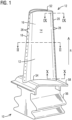
- the airfoil 10 is a turbine blade for a gas turbine engine. It should however be noted that aspects of the invention could additionally be incorporated into stationary vanes in a gas turbine engine.
- the airfoil 10 includes an outer wall 12 adapted for use, for example, in a high pressure stage of an axial flow gas turbine engine.
- the outer wall 12 delimits a hollow interior 11 (see FIG. 2 ).
- the outer wall 12 extends span-wise along a radial direction R of the turbine engine and includes a generally concave shaped pressure sidewall 14 and a generally convex shaped suction sidewall 16.
- the pressure sidewall 14 and the suction sidewall 16 are joined at a leading edge 18 and at a trailing edge 20.
- the outer wall 12 may be coupled to a root 56 at a platform 58.
- the root 56 may couple the turbine airfoil 10 to a disc (not shown) of the turbine engine.
- the outer wall 12 is delimited in the radial direction by a radially outer airfoil end face (airfoil tip cap) 52 and a radially inner airfoil end face 54 coupled to the platform 58.
- a chordal axis 30 may be defined extending centrally between the pressure sidewall 14 and the suction sidewall 16.
- the relative term “forward” refers to a direction along the chordal axis 30 toward the leading edge 18, while the relative term “aft” refers to a direction along the chordal axis 30 toward the trailing edge 20.
- internal passages and cooling circuits are formed by radial coolant cavities 41a-f that are created by internal partition walls or ribs 40a-e which connect the pressure and suction sidewalls 14 and 16 along a radial extent.
- coolant may enter one or more of the radial cavities 41a-f via openings provided in the root of the blade 10, from which the coolant may traverse into adjacent radial coolant cavities, for example, via one or more serpentine cooling circuits. Examples of such cooling schemes are known in the art and will not be further discussed herein. Having traversed the radial coolant cavities, the coolant may be discharged from the airfoil 10 into the hot gas path, for example via exhaust orifices 26, 28 located along the leading edge 18 and the trailing edge 20 respectively. Although not shown in the drawings, exhaust orifices may be provided at multiple locations, including anywhere on the pressure sidewall 16, suction sidewall 18, and the airfoil tip 52.
- the aft-most radial coolant cavity 41f which is adjacent to the trailing edge 20, is referred to herein as the trailing edge coolant cavity 41f.
- the coolant may traverse axially through an internal arrangement 50 of trailing edge cooling features, located in the trailing edge coolant cavity 41e, before leaving the airfoil 10 via coolant exit slots 28 arranged along the trailing edge 20.
- Conventional trailing edge cooling features included a series of impingement plates, typically two or three in number, arranged next to each other along the chordal axis. However, this arrangement provides that the coolant travels only a short distance before exiting the airfoil at the trailing edge. It may be desirable to have a longer coolant flow path along the trailing edge portion to have more surface area for transfer of heat, to improve cooling efficiency and reduce coolant flow requirement.
- the present embodiment provides an improved arrangement of trailing edge cooling features.
- the impingement plates are replaced by an array of cooling features embodied as pins 22.
- Each feature or pin 22 extends all the way from the pressure sidewall 14 to the suction sidewall 16 as shown in FIG 3 .
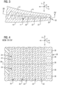
- the features 22 are arranged in radial rows as shown in FIG. 4 .
- the features 22 in each row are interspaced to define axial coolant passages 24, with each coolant passage 24 extending all the way from the pressure sidewall 14 to the suction sidewall 16.
- the rows, in this case fourteen in number, are spaced along the chordal axis 30 to define radial coolant passages 25.
- the features 22 in adjacent rows are staggered in the radial direction.
- the axial coolant passages 24 of the array are fluidically interconnected via the radial flow passages 25, to lead a pressurized coolant in the trailing edge coolant cavity 41f toward the coolant exit slots 28 at the trailing edge 20 via a serial impingement scheme.
- the pressurized coolant flowing generally forward-to-aft impinges serially on to the rows of features 22, leading to a transfer of heat to the coolant accompanied by a drop in pressure of the coolant.
- Heat may be transferred from the outer wall 12 to the coolant by way of convection and/or impingement cooling, usually a combination of both.
- each feature 22 is elongated along the radial direction. That is to say, each feature 22 has a length in the radial direction which is greater than a width in the chord-wise direction.
- a higher aspect ratio provides a longer flow path for the coolant in the passages 25, leading to increased cooling surface area and thereby higher convective heat transfer.
- the described arrangement provides a longer flow path for the coolant and has been shown to increase both heat transfer and pressure drop to restrict the coolant flow rate. Such an arrangement may thus be suitable in advanced turbine blade applications which require smaller amounts of cooling air.
- the exemplary turbine airfoil 10 is manufactured by a casting process involving a casting core, typically made of a ceramic material.
- the core material represents the hollow coolant flow passages inside turbine airfoil 10. It is beneficial for the casting core to have sufficient structural strength to survive through the handling during the casting process.
- the coolant exit slots 28 at the trailing edge 20 may be designed to have larger dimensions at the span-wise ends of the airfoil, i.e., adjacent to the root and the tip of the airfoil 10, to form a stronger picture frame like configuration. However, such a configuration may result in higher coolant flow near the airfoil root and tip than desired.
- Embodiments of the present invention provide an improvement to achieve not only a strong casting core but also a limitation in the coolant flow.
- FIG. 5A-B , 6A-B and 7-8 illustrate portion of an exemplary casting core for manufacturing the inventive turbine airfoil 10.
- the illustrated core element 141f represents the trailing edge coolant cavity 41f of the turbine airfoil 10.
- the core element 141f has a core pressure side 114 and a core suction side 116 extending in a span-wise direction, and further extending chord-wise toward a core trailing edge 120.
- FIG. 5A and 5B illustrate a views looking from the core suction side 116, with FIG. 5A illustrating a first span-wise end portion which is adjacent to the radially outer airfoil end face 52 (airfoil tip cap), and FIG.
- FIG. 5B illustrating a second span-wise end portion which is adjacent to the radially inner airfoil end face 54 coupled to the platform 58.
- FIG. 6A-B illustrate views looking from the core pressure side 114, with FIG. 6A illustrating a first span-wise end portion which is adjacent to the radially outer airfoil end face 52 (airfoil tip cap), and FIG. 6B illustrating a second span-wise end portion which is adjacent to the radially inner airfoil end face 54 coupled to the platform 58.
- the core element 141f comprises an array of perforations 122 there-through, located between span-wise ends of the core element 141f. Each perforation 122 extends all the way from the core pressure side 114 to the core suction side 116.
- the perforations 122 form the cooling features the 22 in the trailing edge coolant cavity 41f (see FIG. 4 ).
- Each perforation 122 is correspondingly elongated in the radial or span-wise direction.
- the array comprises multiple radial rows of said perforations 122 with the perforations 122 in each row being interspaced radially by interstitial core elements 124 that form the coolant passages 24 in the turbine airfoil 10.
- the core elements 128 form the trailing edge coolant exit slots 28 of the turbine airfoil 10.
- the array of perforations 122 is located between the span-wise ends of the core element 141f, but does not extend all the way up to the span-wise ends thereof.
- indentations are provided on the core pressure side 114 and/or the core suction side 116.
- indentations are provided at a chord-wise upstream location of the core element 141f, which is generally thicker.
- perforations may formed through the core element 141f along the radially outer span-wise end thereof.
- chord-wise spaced indentations 172A and 182A are provided on the first and second span-wise ends of the core pressure side 114 respectively ( FIG. 6A-B ) and chord-wise spaced indentations 172B and 182B are provided on the first and second span-wise ends of the core suction side 116 respectively ( FIG. 5A-B ).
- the indentations 172A-B and 182A-B form framing features 72A-B, 82A-B in a respective framing passage 70, 80 in the trailing edge coolant cavity 41f of the turbine airfoil 10.
- the framing passages 70 and 80 are located at first and second span-wise ends respectively of the trailing edge coolant cavity 41f.
- the respective framing passage 70, 80 is located between the cooling features 22 and a respective airfoil radial end face 52, 54.
- the framing features 72A-B, 82A-B are configured as ribs.
- the ribs 72A, 82A protrude from the pressure sidewall 14 of the airfoil 10
- the ribs 72B, 82B protrude from the suction sidewall 16 of the airfoil 10.
- Each of the ribs 72A-B, 82A-B extends only partially between the pressure sidewall 14 and the suction sidewall 16.
- the indentations 172A-B, 182A-B maintain strength of the ceramic core at the root and the tip, as opposed to complete perforations through the core pressure and suction sides.
- the indentations 172A on the core pressure side 114 and the indentations 172B on the core suction side 116 are alternately positioned along the chord-wise direction.
- the indentations 182A on the core pressure side 114 and the indentations 182B on the core suction side 116 are alternately positioned along the chord-wise direction.
- FIG. 9 and 10 The resultant framing features are illustrated in FIG. 9 and 10 .
- the ribs 72A on the pressure sidewall 14 and the ribs 72B on the suction sidewall 16 are alternately positioned in the chord-wise direction to define a zigzag flow path F of the coolant flowing in the framing passage 70 toward the coolant exit slots 28.
- the ribs 82A on the pressure sidewall 14 and the ribs 82B on the suction sidewall 16 are alternately positioned in the chord-wise direction to define a zigzag flow path F of the coolant flowing in the framing passage 80 toward the coolant exit slots 28.
- each zigzag flow path F is configured as a mini-serpentine path where the coolant flow direction alternates between the pressure sidewall 14 and the suction sidewall 16 while generally chord-wise in the framing passage 70, 80 toward the trailing edge coolant exit slots 28.
- the zigzag flow path F provides a highly tortuous flow passage for the coolant to restrict coolant flow, particularly at the span-wise ends (near the root and the tip of the airfoil) where the trailing edge coolant exit slots 28 have a larger dimension to maintain core stability.
- the zigzag passages provide a high pressure drop and high heat transfer for very limited coolant flow rate while maintaining a strong ceramic core.
Landscapes
- Engineering & Computer Science (AREA)
- Mechanical Engineering (AREA)
- General Engineering & Computer Science (AREA)
- Physics & Mathematics (AREA)
- Fluid Mechanics (AREA)
- Turbine Rotor Nozzle Sealing (AREA)
- Chemical & Material Sciences (AREA)
- Ceramic Engineering (AREA)
- Materials Engineering (AREA)
Claims (8)
- Turbinenlaufschaufel (10) mit einem Schaufelblatt, umfassend:eine Außenwand (12), die einen Schaufelblattinnenraum (11) begrenzt, wobei sich die Außenwand (12) spannweitenweise entlang einer radialen Richtung eines Turbinenmotors erstreckt und aus einer Druckseitenwand (14) und einer Saugseitenwand (16) gebildet ist, die an einer Vorderkante (18) und an einer Hinterkante (20) verbunden sind,einen Hinterkantenkühlhohlraum (41f), der sich im Schaufelblattinnenraum (11) zwischen der Druckseitenwand (14) und der Saugseitenwand (16) befindet, wobei der Hinterkantenkühlhohlraum (41f) angrenzend an die Hinterkante (20) positioniert und in Fluidverbindung mit einer Vielzahl von Kühlmittelaustrittsschlitzen (28) steht, die entlang der Hinterkante (20) angeordnet sind,wobei sich eine Vielzahl von Kühlmerkmalen (22) im Hinterkantenkühlhohlraum (41f) befinden und in einem Strömungsweg des Kühlmittels angeordnet sind, das zu den Kühlmittelaustrittsschlitzen (28) fließt,wobei sich die Kühlmerkmale (22) zwischen dem radial äußeren spannweitigen Ende des Hinterkantenkühlhohlraums (41f) und dem radial inneren spannweitigen Ende des Hinterkantenkühlhohlraums befinden,wobei jedes Kühlmerkmal (22) eine Länge in radialer Richtung aufweist, die größer als eine Breite in Sehnenlängsrichtung ist,wobei die Kühlmerkmale eine Anordnung von Stiften (22) umfassen,wobei sich jeder Stift (22) von der Druckseitenwand (14) zur Saugseitenwand (16) erstreckt, wobei die Anordnung mehrere in Sehnenlängsrichtung beabstandete radiale Reihen der Stifte (22) umfasst, wobei die Stifte (22) in jeder Reihe radial beabstandet sind, um dazwischen Kühlmitteldurchgänge (24) zu definieren,wobei mindestens ein einrahmender Durchgang (70, 80) an einem spannweitigen Ende des Hinterkantenkühlhohlraums (41f) ausgebildet ist, wobei der mindestens eine einrahmende Durchgang (70, 80) einen ersten einrahmenden Durchgang (70) und einen zweiten einrahmenden Durchgang (80) umfasst, die an spannweitig gegenüberliegenden Enden des Hinterkantenkühlhohlraums (41f) ausgebildet sind, undeinrahmende Merkmale (72A-B, 82A-B), die sich sowohl im ersten als auch im zweiten einrahmenden Durchgang (70, 80) befinden, wobei die einrahmenden Merkmale als Rippen (72A-B, 82A-B) ausgebildet sind, die in Sehnenlängsrichtung beabstandet an der Druckseitenwand (14) und/oder der Saugseitenwand (18) angeordnet sind und von der Druckseitenwand (14) und/oder der Saugseitenwand (16) vorstehen, wobei sich die Rippen (72A-B, 82A-B) teilweise zwischen der Druckseitenwand (14) und der Saugseitenwand (16) erstrecken, wobei jede Rippe (72A-B, 82A-B) in radialer Richtung mit einer entsprechenden Reihe der Stifte (22) ausgerichtet ist.
- Turbinenlaufschaufel nach Anspruch 1, wobei sich der einrahmende Durchgang (70, 80) in Sehnenlängsrichtung zur Hinterkante (20) erstreckt.
- Turbinenlaufschaufel nach Anspruch 2, wobei die Rippen (72A-B, 82A-B) an der Druckseitenwand (14) und an der Saugseitenwand (16) ausgebildet sind, und
wobei die Rippen (72A, 82A) an der Druckseitenwand (14) und die Rippen (72B, 82B) an der Saugseitenwand (16) abwechselnd in Sehnenlängsrichtung positioniert sind, um einen Zickzack-Strömungsweg (F) des im einrahmenden Durchgang (70, 80) zu den Austrittsschlitzen (28) fließenden Kühlmittels zu definieren. - Turbinenlaufschaufel nach Anspruch 1, wobei jeder Stift (22) in radialer Richtung länglich ist.
- Turbinenlaufschaufel nach Anspruch 1, wobei sich der einrahmende Durchgang (70, 80) zwischen den Kühlmerkmalen (22) und einer radialen Stirnfläche (52, 54) des Schaufelblatts befindet.
- Gießkern zur Herstellung einer Turbinenlaufschaufel (10) mit einem Schaufelblatt, umfassend:ein Kernelement (141f), das einen Hinterkantenkühlhohlraum (41f) des Turbinenlaufschaufelblatts (10) bildet, wobei das Kernelement (141f) eine Kerndruckseite (114) und eine Kernsaugseite (116) umfasst, die sich in Spannweitenrichtung erstrecken und sich ferner in Sehnenlängsrichtung zu einer Kernhinterkante (120) erstrecken,wobei eine Vielzahl von in Sehnenlängsrichtung beabstandeten Vertiefungen (172A-B, 182A-B) auf der Kerndruckseite (114) und/oder der Kernsaugseite (116) an jedem spannweitigen Ende des Kernelements (141f) vorgesehen sind, wobei die Vertiefungen (172A-B, 182A-B) einrahmende Merkmale (72A-B, 82A-B) im Hinterkantenkühlhohlraum (41f) des Turbinenlaufschaufelblatts (10) bilden,wobei der Gießkern ferner eine Anordnung von Perforationen (122) durch das Kernelement (141f) umfasst, die sich zwischen dem radial äußeren spannweitigen Ende des Kernelements (141f) und dem radial inneren spannweitigen Ende des Kernelements befinden,wobei die Perforationen (122) Kühlmerkmale (22) im Hinterkantenkühlhohlraum (41f) des Turbinenlaufschaufelblatts (10) bilden,wobei jedes Kühlmerkmal (22) eine Länge in radialer Richtung aufweist, die größer als eine Breite in Sehnenlängsrichtung ist,wobei sich jede Perforation (122) von der Kerndruckseite (114) zur Kernsaugseite (116) erstreckt, und wobei die Kernhinterkante (120) Elemente (128) umfasst, die eine Vielzahl von entlang der Hinterkante positionierten Kühlmittelaustrittsschlitzen bilden,wobei die Anordnung von Perforationen mehrere radiale Reihen der Perforationen (122) umfasst, die in Sehnenlängsrichtung beabstandet sind,
undwobei jede Vertiefung (172A-B, 182A-B) in radialer Richtung mit einer entsprechenden Reihe der Perforationen (122) ausgerichtet ist und wobei die Perforationen (122) in jeder Reihe radial durch dazwischenliegende Kernelemente (124) beabstandet sind, die Kühlmitteldurchgänge im Turbinenlaufschaufelblatt bilden. - Gießkern nach Anspruch 6, wobei die Vertiefungen (172A-B, 182A-B) auf der Kerndruckseite (114) und auf der Kernsaugseite (116) ausgebildet sind, und
wobei die Vertiefungen (172A, 182A) auf der Kerndruckseite (114) und die Vertiefungen (172B, 182B) auf der Kernsaugseite (116) abwechselnd in Sehnenlängsrichtung positioniert sind. - Gießkern nach Anspruch 6 oder 7, wobei jede Perforation (122) in radialer Richtung länglich ist.
Applications Claiming Priority (2)
| Application Number | Priority Date | Filing Date | Title |
|---|---|---|---|
| US201662311628P | 2016-03-22 | 2016-03-22 | |
| PCT/US2016/058361 WO2017164935A1 (en) | 2016-03-22 | 2016-10-24 | Turbine airfoil with trailing edge framing features |
Publications (2)
| Publication Number | Publication Date |
|---|---|
| EP3417153A1 EP3417153A1 (de) | 2018-12-26 |
| EP3417153B1 true EP3417153B1 (de) | 2024-12-04 |
Family
ID=59153246
Family Applications (1)
| Application Number | Title | Priority Date | Filing Date |
|---|---|---|---|
| EP16880177.7A Active EP3417153B1 (de) | 2016-03-22 | 2016-10-24 | Turbinenlaufschaufel mit schaufelblatt mit einrahmenden merkmalen im hinterkantenbereich |
Country Status (5)
| Country | Link |
|---|---|
| US (1) | US11193378B2 (de) |
| EP (1) | EP3417153B1 (de) |
| JP (1) | JP6685425B2 (de) |
| CN (1) | CN108779678B (de) |
| WO (1) | WO2017164935A1 (de) |
Families Citing this family (3)
| Publication number | Priority date | Publication date | Assignee | Title |
|---|---|---|---|---|
| EP3645838B1 (de) * | 2017-06-30 | 2022-06-01 | Siemens Energy Global GmbH & Co. KG | Turbinenschaufel mit hinterkantenmerkmalen und gusskern |
| US10787932B2 (en) * | 2018-07-13 | 2020-09-29 | Honeywell International Inc. | Turbine blade with dust tolerant cooling system |
| US11852024B2 (en) * | 2020-12-18 | 2023-12-26 | Ge Aviation Systems Llc | Electrical strut for a turbine engine |
Citations (2)
| Publication number | Priority date | Publication date | Assignee | Title |
|---|---|---|---|---|
| EP2143883A1 (de) * | 2008-07-10 | 2010-01-13 | Siemens Aktiengesellschaft | Turbinenschaufel und entsprechender Gusskern |
| US8506252B1 (en) * | 2010-10-21 | 2013-08-13 | Florida Turbine Technologies, Inc. | Turbine blade with multiple impingement cooling |
Family Cites Families (14)
| Publication number | Priority date | Publication date | Assignee | Title |
|---|---|---|---|---|
| US5752801A (en) | 1997-02-20 | 1998-05-19 | Westinghouse Electric Corporation | Apparatus for cooling a gas turbine airfoil and method of making same |
| US6974308B2 (en) * | 2001-11-14 | 2005-12-13 | Honeywell International, Inc. | High effectiveness cooled turbine vane or blade |
| US6602047B1 (en) * | 2002-02-28 | 2003-08-05 | General Electric Company | Methods and apparatus for cooling gas turbine nozzles |
| US7713027B2 (en) * | 2006-08-28 | 2010-05-11 | United Technologies Corporation | Turbine blade with split impingement rib |
| US7785070B2 (en) * | 2007-03-27 | 2010-08-31 | Siemens Energy, Inc. | Wavy flow cooling concept for turbine airfoils |
| GB2452327B (en) * | 2007-09-01 | 2010-02-03 | Rolls Royce Plc | A cooled component |
| JP2011085084A (ja) * | 2009-10-16 | 2011-04-28 | Ihi Corp | タービン翼 |
| EP2378073A1 (de) * | 2010-04-14 | 2011-10-19 | Siemens Aktiengesellschaft | Lauf- oder Leitschaufel für eine Turbomaschine |
| EP2426317A1 (de) * | 2010-09-03 | 2012-03-07 | Siemens Aktiengesellschaft | Turbinenschaufel für eine Gasturbine |
| US9546554B2 (en) * | 2012-09-27 | 2017-01-17 | Honeywell International Inc. | Gas turbine engine components with blade tip cooling |
| US8936067B2 (en) * | 2012-10-23 | 2015-01-20 | Siemens Aktiengesellschaft | Casting core for a cooling arrangement for a gas turbine component |
| EP3030750A4 (de) * | 2013-08-05 | 2017-04-26 | United Technologies Corporation | Spitzenkühlung für tragflächenaustrittskanten |
| US20160333699A1 (en) * | 2014-01-30 | 2016-11-17 | United Technologies Corporation | Trailing edge cooling pedestal configuration for a gas turbine engine airfoil |
| US10053988B2 (en) * | 2015-12-10 | 2018-08-21 | General Electric Company | Article and method of forming an article |
-
2016
- 2016-10-24 CN CN201680083937.7A patent/CN108779678B/zh active Active
- 2016-10-24 JP JP2018549889A patent/JP6685425B2/ja active Active
- 2016-10-24 EP EP16880177.7A patent/EP3417153B1/de active Active
- 2016-10-24 US US16/086,226 patent/US11193378B2/en active Active
- 2016-10-24 WO PCT/US2016/058361 patent/WO2017164935A1/en not_active Ceased
Patent Citations (2)
| Publication number | Priority date | Publication date | Assignee | Title |
|---|---|---|---|---|
| EP2143883A1 (de) * | 2008-07-10 | 2010-01-13 | Siemens Aktiengesellschaft | Turbinenschaufel und entsprechender Gusskern |
| US8506252B1 (en) * | 2010-10-21 | 2013-08-13 | Florida Turbine Technologies, Inc. | Turbine blade with multiple impingement cooling |
Also Published As
| Publication number | Publication date |
|---|---|
| US20200291787A1 (en) | 2020-09-17 |
| JP2019512641A (ja) | 2019-05-16 |
| CN108779678B (zh) | 2021-05-28 |
| JP6685425B2 (ja) | 2020-04-22 |
| US11193378B2 (en) | 2021-12-07 |
| CN108779678A (zh) | 2018-11-09 |
| WO2017164935A1 (en) | 2017-09-28 |
| EP3417153A1 (de) | 2018-12-26 |
Similar Documents
| Publication | Publication Date | Title |
|---|---|---|
| EP1008724B1 (de) | Schaufel eines Gasturbinentriebwerks | |
| US6206638B1 (en) | Low cost airfoil cooling circuit with sidewall impingement cooling chambers | |
| CN1970997B (zh) | 图案化冷却的涡轮机翼型部 | |
| EP3341567B1 (de) | Innengekühlte turbinenschaufel mit strömungsverdrängungsmerkmal | |
| CN115075889A (zh) | 改进的涡轮叶片冷却系统 | |
| EP3325774B1 (de) | Turbinenschaufel mit interner prallkühlfunktion | |
| EP3399145B1 (de) | Schaufelprofil mit vorderkantenhybridhohlraum | |
| EP3645838B1 (de) | Turbinenschaufel mit hinterkantenmerkmalen und gusskern | |
| EP3417153B1 (de) | Turbinenlaufschaufel mit schaufelblatt mit einrahmenden merkmalen im hinterkantenbereich | |
| EP3353384B1 (de) | Turbinenschaufel mit hinterkantenkühlung mit axialen trennwänden | |
| EP3617454B1 (de) | Kollektorwand mit variabler wärmeübertragung | |
| EP3803057B1 (de) | Schaufelblatt für einen turbinenmotor mit stiften | |
| CN113874600A (zh) | 具有蛇形通道的涡轮叶片 | |
| WO2017105379A1 (en) | Turbine airfoil with profiled flow blocking feature for enhanced near wall cooling | |
| WO2017095438A1 (en) | Turbine airfoil with biased trailing edge cooling arrangement | |
| WO2018080416A1 (en) | Turbine airfoil with near wall passages without connecting ribs |
Legal Events
| Date | Code | Title | Description |
|---|---|---|---|
| STAA | Information on the status of an ep patent application or granted ep patent |
Free format text: STATUS: UNKNOWN |
|
| STAA | Information on the status of an ep patent application or granted ep patent |
Free format text: STATUS: THE INTERNATIONAL PUBLICATION HAS BEEN MADE |
|
| PUAI | Public reference made under article 153(3) epc to a published international application that has entered the european phase |
Free format text: ORIGINAL CODE: 0009012 |
|
| STAA | Information on the status of an ep patent application or granted ep patent |
Free format text: STATUS: REQUEST FOR EXAMINATION WAS MADE |
|
| 17P | Request for examination filed |
Effective date: 20180918 |
|
| AK | Designated contracting states |
Kind code of ref document: A1 Designated state(s): AL AT BE BG CH CY CZ DE DK EE ES FI FR GB GR HR HU IE IS IT LI LT LU LV MC MK MT NL NO PL PT RO RS SE SI SK SM TR |
|
| AX | Request for extension of the european patent |
Extension state: BA ME |
|
| STAA | Information on the status of an ep patent application or granted ep patent |
Free format text: STATUS: EXAMINATION IS IN PROGRESS |
|
| DAV | Request for validation of the european patent (deleted) | ||
| DAX | Request for extension of the european patent (deleted) | ||
| 17Q | First examination report despatched |
Effective date: 20190625 |
|
| RAP1 | Party data changed (applicant data changed or rights of an application transferred) |
Owner name: SIEMENS ENERGY GLOBAL GMBH & CO. KG |
|
| GRAP | Despatch of communication of intention to grant a patent |
Free format text: ORIGINAL CODE: EPIDOSNIGR1 |
|
| STAA | Information on the status of an ep patent application or granted ep patent |
Free format text: STATUS: GRANT OF PATENT IS INTENDED |
|
| INTG | Intention to grant announced |
Effective date: 20240620 |
|
| GRAS | Grant fee paid |
Free format text: ORIGINAL CODE: EPIDOSNIGR3 |
|
| GRAA | (expected) grant |
Free format text: ORIGINAL CODE: 0009210 |
|
| STAA | Information on the status of an ep patent application or granted ep patent |
Free format text: STATUS: THE PATENT HAS BEEN GRANTED |
|
| AK | Designated contracting states |
Kind code of ref document: B1 Designated state(s): AL AT BE BG CH CY CZ DE DK EE ES FI FR GB GR HR HU IE IS IT LI LT LU LV MC MK MT NL NO PL PT RO RS SE SI SK SM TR |
|
| REG | Reference to a national code |
Ref country code: GB Ref legal event code: FG4D |
|
| REG | Reference to a national code |
Ref country code: CH Ref legal event code: EP |
|
| REG | Reference to a national code |
Ref country code: DE Ref legal event code: R096 Ref document number: 602016090541 Country of ref document: DE |
|
| REG | Reference to a national code |
Ref country code: IE Ref legal event code: FG4D |
|
| REG | Reference to a national code |
Ref country code: LT Ref legal event code: MG9D |
|
| REG | Reference to a national code |
Ref country code: NL Ref legal event code: MP Effective date: 20241204 |
|
| PG25 | Lapsed in a contracting state [announced via postgrant information from national office to epo] |
Ref country code: HR Free format text: LAPSE BECAUSE OF FAILURE TO SUBMIT A TRANSLATION OF THE DESCRIPTION OR TO PAY THE FEE WITHIN THE PRESCRIBED TIME-LIMIT Effective date: 20241204 |
|
| PG25 | Lapsed in a contracting state [announced via postgrant information from national office to epo] |
Ref country code: FI Free format text: LAPSE BECAUSE OF FAILURE TO SUBMIT A TRANSLATION OF THE DESCRIPTION OR TO PAY THE FEE WITHIN THE PRESCRIBED TIME-LIMIT Effective date: 20241204 |
|
| PG25 | Lapsed in a contracting state [announced via postgrant information from national office to epo] |
Ref country code: BG Free format text: LAPSE BECAUSE OF FAILURE TO SUBMIT A TRANSLATION OF THE DESCRIPTION OR TO PAY THE FEE WITHIN THE PRESCRIBED TIME-LIMIT Effective date: 20241204 |
|
| PG25 | Lapsed in a contracting state [announced via postgrant information from national office to epo] |
Ref country code: ES Free format text: LAPSE BECAUSE OF FAILURE TO SUBMIT A TRANSLATION OF THE DESCRIPTION OR TO PAY THE FEE WITHIN THE PRESCRIBED TIME-LIMIT Effective date: 20241204 |
|
| PG25 | Lapsed in a contracting state [announced via postgrant information from national office to epo] |
Ref country code: NO Free format text: LAPSE BECAUSE OF FAILURE TO SUBMIT A TRANSLATION OF THE DESCRIPTION OR TO PAY THE FEE WITHIN THE PRESCRIBED TIME-LIMIT Effective date: 20250304 |
|
| PG25 | Lapsed in a contracting state [announced via postgrant information from national office to epo] |
Ref country code: GR Free format text: LAPSE BECAUSE OF FAILURE TO SUBMIT A TRANSLATION OF THE DESCRIPTION OR TO PAY THE FEE WITHIN THE PRESCRIBED TIME-LIMIT Effective date: 20250305 Ref country code: LV Free format text: LAPSE BECAUSE OF FAILURE TO SUBMIT A TRANSLATION OF THE DESCRIPTION OR TO PAY THE FEE WITHIN THE PRESCRIBED TIME-LIMIT Effective date: 20241204 |
|
| PG25 | Lapsed in a contracting state [announced via postgrant information from national office to epo] |
Ref country code: RS Free format text: LAPSE BECAUSE OF FAILURE TO SUBMIT A TRANSLATION OF THE DESCRIPTION OR TO PAY THE FEE WITHIN THE PRESCRIBED TIME-LIMIT Effective date: 20250304 |
|
| PG25 | Lapsed in a contracting state [announced via postgrant information from national office to epo] |
Ref country code: NL Free format text: LAPSE BECAUSE OF FAILURE TO SUBMIT A TRANSLATION OF THE DESCRIPTION OR TO PAY THE FEE WITHIN THE PRESCRIBED TIME-LIMIT Effective date: 20241204 |
|
| REG | Reference to a national code |
Ref country code: AT Ref legal event code: MK05 Ref document number: 1748368 Country of ref document: AT Kind code of ref document: T Effective date: 20241204 |
|
| PG25 | Lapsed in a contracting state [announced via postgrant information from national office to epo] |
Ref country code: SM Free format text: LAPSE BECAUSE OF FAILURE TO SUBMIT A TRANSLATION OF THE DESCRIPTION OR TO PAY THE FEE WITHIN THE PRESCRIBED TIME-LIMIT Effective date: 20241204 |
|
| PG25 | Lapsed in a contracting state [announced via postgrant information from national office to epo] |
Ref country code: PL Free format text: LAPSE BECAUSE OF FAILURE TO SUBMIT A TRANSLATION OF THE DESCRIPTION OR TO PAY THE FEE WITHIN THE PRESCRIBED TIME-LIMIT Effective date: 20241204 |
|
| PG25 | Lapsed in a contracting state [announced via postgrant information from national office to epo] |
Ref country code: IS Free format text: LAPSE BECAUSE OF FAILURE TO SUBMIT A TRANSLATION OF THE DESCRIPTION OR TO PAY THE FEE WITHIN THE PRESCRIBED TIME-LIMIT Effective date: 20250404 |
|
| PG25 | Lapsed in a contracting state [announced via postgrant information from national office to epo] |
Ref country code: PT Free format text: LAPSE BECAUSE OF FAILURE TO SUBMIT A TRANSLATION OF THE DESCRIPTION OR TO PAY THE FEE WITHIN THE PRESCRIBED TIME-LIMIT Effective date: 20250404 |
|
| PG25 | Lapsed in a contracting state [announced via postgrant information from national office to epo] |
Ref country code: EE Free format text: LAPSE BECAUSE OF FAILURE TO SUBMIT A TRANSLATION OF THE DESCRIPTION OR TO PAY THE FEE WITHIN THE PRESCRIBED TIME-LIMIT Effective date: 20241204 |
|
| PG25 | Lapsed in a contracting state [announced via postgrant information from national office to epo] |
Ref country code: AT Free format text: LAPSE BECAUSE OF FAILURE TO SUBMIT A TRANSLATION OF THE DESCRIPTION OR TO PAY THE FEE WITHIN THE PRESCRIBED TIME-LIMIT Effective date: 20241204 Ref country code: RO Free format text: LAPSE BECAUSE OF FAILURE TO SUBMIT A TRANSLATION OF THE DESCRIPTION OR TO PAY THE FEE WITHIN THE PRESCRIBED TIME-LIMIT Effective date: 20241204 |
|
| PG25 | Lapsed in a contracting state [announced via postgrant information from national office to epo] |
Ref country code: SK Free format text: LAPSE BECAUSE OF FAILURE TO SUBMIT A TRANSLATION OF THE DESCRIPTION OR TO PAY THE FEE WITHIN THE PRESCRIBED TIME-LIMIT Effective date: 20241204 |
|
| PG25 | Lapsed in a contracting state [announced via postgrant information from national office to epo] |
Ref country code: CZ Free format text: LAPSE BECAUSE OF FAILURE TO SUBMIT A TRANSLATION OF THE DESCRIPTION OR TO PAY THE FEE WITHIN THE PRESCRIBED TIME-LIMIT Effective date: 20241204 |
|
| REG | Reference to a national code |
Ref country code: DE Ref legal event code: R097 Ref document number: 602016090541 Country of ref document: DE |
|
| PG25 | Lapsed in a contracting state [announced via postgrant information from national office to epo] |
Ref country code: SE Free format text: LAPSE BECAUSE OF FAILURE TO SUBMIT A TRANSLATION OF THE DESCRIPTION OR TO PAY THE FEE WITHIN THE PRESCRIBED TIME-LIMIT Effective date: 20241204 |
|
| PG25 | Lapsed in a contracting state [announced via postgrant information from national office to epo] |
Ref country code: DK Free format text: LAPSE BECAUSE OF FAILURE TO SUBMIT A TRANSLATION OF THE DESCRIPTION OR TO PAY THE FEE WITHIN THE PRESCRIBED TIME-LIMIT Effective date: 20241204 |
|
| PLBE | No opposition filed within time limit |
Free format text: ORIGINAL CODE: 0009261 |
|
| STAA | Information on the status of an ep patent application or granted ep patent |
Free format text: STATUS: NO OPPOSITION FILED WITHIN TIME LIMIT |
|
| REG | Reference to a national code |
Ref country code: CH Ref legal event code: L10 Free format text: ST27 STATUS EVENT CODE: U-0-0-L10-L00 (AS PROVIDED BY THE NATIONAL OFFICE) Effective date: 20251015 |
|
| REG | Reference to a national code |
Ref country code: CH Ref legal event code: U11 Free format text: ST27 STATUS EVENT CODE: U-0-0-U10-U11 (AS PROVIDED BY THE NATIONAL OFFICE) Effective date: 20251101 |
|
| 26N | No opposition filed |
Effective date: 20250905 |
|
| PGFP | Annual fee paid to national office [announced via postgrant information from national office to epo] |
Ref country code: DE Payment date: 20251028 Year of fee payment: 10 |
|
| PGFP | Annual fee paid to national office [announced via postgrant information from national office to epo] |
Ref country code: IT Payment date: 20251022 Year of fee payment: 10 |
|
| PGFP | Annual fee paid to national office [announced via postgrant information from national office to epo] |
Ref country code: CH Payment date: 20251101 Year of fee payment: 10 |