EP3416876B1 - Wear pad for a track of a tracked vehicle, track, and construction machine - Google Patents
Wear pad for a track of a tracked vehicle, track, and construction machine Download PDFInfo
- Publication number
- EP3416876B1 EP3416876B1 EP17704774.3A EP17704774A EP3416876B1 EP 3416876 B1 EP3416876 B1 EP 3416876B1 EP 17704774 A EP17704774 A EP 17704774A EP 3416876 B1 EP3416876 B1 EP 3416876B1
- Authority
- EP
- European Patent Office
- Prior art keywords
- wear pad
- accordance
- longitudinal direction
- wear
- crawler track
- Prior art date
- Legal status (The legal status is an assumption and is not a legal conclusion. Google has not performed a legal analysis and makes no representation as to the accuracy of the status listed.)
- Active
Links
- 238000010276 construction Methods 0.000 title claims description 5
- 239000000463 material Substances 0.000 claims description 21
- 230000003014 reinforcing effect Effects 0.000 claims description 18
- 229920002635 polyurethane Polymers 0.000 claims description 5
- 239000004814 polyurethane Substances 0.000 claims description 5
- 229920001971 elastomer Polymers 0.000 claims description 3
- 239000000806 elastomer Substances 0.000 claims description 3
- 238000003801 milling Methods 0.000 claims description 3
- 238000007373 indentation Methods 0.000 claims 1
- 230000002787 reinforcement Effects 0.000 description 30
- 230000000295 complement effect Effects 0.000 description 3
- 238000004519 manufacturing process Methods 0.000 description 3
- 238000004040 coloring Methods 0.000 description 1
- 238000012423 maintenance Methods 0.000 description 1
- 230000000149 penetrating effect Effects 0.000 description 1
- 230000002028 premature Effects 0.000 description 1
- 230000001681 protective effect Effects 0.000 description 1
- 230000000717 retained effect Effects 0.000 description 1
Images


Classifications
-
- B—PERFORMING OPERATIONS; TRANSPORTING
- B62—LAND VEHICLES FOR TRAVELLING OTHERWISE THAN ON RAILS
- B62D—MOTOR VEHICLES; TRAILERS
- B62D55/00—Endless track vehicles
- B62D55/08—Endless track units; Parts thereof
- B62D55/18—Tracks
- B62D55/26—Ground engaging parts or elements
- B62D55/28—Ground engaging parts or elements detachable
-
- B—PERFORMING OPERATIONS; TRANSPORTING
- B62—LAND VEHICLES FOR TRAVELLING OTHERWISE THAN ON RAILS
- B62D—MOTOR VEHICLES; TRAILERS
- B62D55/00—Endless track vehicles
- B62D55/08—Endless track units; Parts thereof
- B62D55/18—Tracks
- B62D55/26—Ground engaging parts or elements
- B62D55/275—Ground engaging parts or elements with street plate, i.e. means to prevent tread from cutting into road surface
-
- B—PERFORMING OPERATIONS; TRANSPORTING
- B62—LAND VEHICLES FOR TRAVELLING OTHERWISE THAN ON RAILS
- B62D—MOTOR VEHICLES; TRAILERS
- B62D55/00—Endless track vehicles
- B62D55/32—Assembly, disassembly, repair or servicing of endless-track systems
Definitions
- the invention relates to an exchangeable wear pad for a crawler belt of a tracked vehicle, according to the preamble of claim 1.
- Exchangeable wear pads for crawlers are known from the prior art, which can be releasably attached to an intermediate plate of the crawler.
- the wear pads generally have four outwardly protruding screw bolts of fastening screws that are spaced apart in the longitudinal direction of the wear pad.
- the fastening screws are passed through reinforcement rails and secured against twisting in a suitable manner.
- the reinforcement rails are encased by the wear pad material with fastening screws arranged at their ends.
- the disadvantage here is that the wear pad material also settles under the reinforcement rail when it is cast around.
- This has the disadvantage that the screw connections with an intermediate plate loosen again during operation due to the soft polyurethane material between the reinforcement rail and the intermediate plate, so that the screw connections have to be retightened regularly.
- the polyurethane material located between the reinforcement rail and the intermediate plate prevents the pre-tensioning of the screw connection from being permanently maintained. It goes without saying that with up to 50 wear pads per crawler track of a chassis and with four chassis per machine, the time required for retensioning the screw connections is considerable, so that increased costs and an increased time requirement arise.
- a contact collar of the reinforcement rail is essentially flush with the wear pad material of the wear pad, so that the wear pad can be rigidly attached to an intermediate plate via the screw connection.
- Two projections extending in the longitudinal direction of the wear pad protrude from the underside of the wear pad, which protrusions into the intermediate plate, as from Fig. 10 visible to intervene.
- alternating transverse forces arise which act on the fastening means and can also lead to premature loosening of the fastening means between the intermediate plate and the crawler belt and between the wear pad and the intermediate plate.
- An inclined position of the construction machine also generates high transverse forces which have to be absorbed by the fastening means of the wear pad and the fastening means of the intermediate plate.
- the invention is therefore based on the object of creating a wear pad for a track of the type mentioned, as well as a track and a construction machine, with which the durability of the screw connections, a wear pad and the manufacturing costs and the time required for assembly and disassembly are improved the wear pad and thus the maintenance costs can be reduced.
- the invention advantageously provides that the projection of the wear pad on the underside facing the track link for at least partial engagement in a recess of the track link adapted to the protrusion has an outer contour that runs at least partially at an angle deviating from the longitudinal direction of the wear pad.
- transverse forces can be absorbed, which act in particular when steering the tracked vehicle in the longitudinal direction of the wear pad.
- the deflection forces and / or inclination of the crawler belt transversely to the direction of movement of the crawler belt form an alternating load on the fastening means, so that the screw connection of the wear pads can loosen under the action of changing transverse forces and may require the screw connections to be retightened.
- the outer contour of the projection protruding on the underside of the wear pad which extends at least partially at an angle deviating from the longitudinal direction of the wear pad, absorbs the transverse forces and thus relieves the fastening means completely or at least to a considerable extent from the alternating load. In this way, it is possible to use only two fastening means that are mutually spaced apart in the longitudinal direction of the wear pad, so that the assembly effort for mounting and dismounting of the wear pad is reduced, almost halved, and the manufacturing costs for the wear pad are also reduced.
- the angle is ⁇ 0 ° and ⁇ 90 °.
- the angle is preferably in the range from 20 ° to 70 ° and particularly preferably 30 ° to 60 °.
- the projection preferably has two side surfaces extending substantially in the longitudinal direction and two end surfaces preferably extending substantially perpendicular to the longitudinal direction.
- the side surfaces of the projection here have the angle according to the invention to the longitudinal direction of the wear pad in order to absorb transverse forces.
- the side surfaces can have a constant distance in the longitudinal direction and thus run parallel to one another. The distance between the side surfaces can also vary in the longitudinal direction.
- Another advantage is that an intermediate plate is no longer required between the track link and the wear pad. This eliminates the need for further fastening means between the crawler belt and the intermediate plate, so that the assembly and disassembly effort is considerably reduced overall.
- the engagement of the projection in a recess which is complementary to the projection and which forms a form fit at least in the longitudinal direction of the wear pad.
- the wear pad contains at least one reinforcement element which is at least predominantly enclosed or encapsulated by wear pad material.
- the reinforcement element increases the rigidity of the wear pad, in particular in the form of a reinforcement rail and enables rigid attachment to the track links without the need to re-tension the fastening means before the running surface of the wear pad is completely worn.
- the wear pad can have at least two fastening means which are arranged at a distance from one another in the longitudinal direction of the wear pad and which are used to fasten the wear pad to the track link.
- the fastening means are preferably arranged in the vicinity of the free ends of the wear pad on the underside in the longitudinal direction.
- the reinforcement element is integrated into the at least one projection of the wear pad. In this way, the part of the wear pad that does not form the projection forms a wear layer that can be almost completely used up.
- the fastening means can be integrated in the reinforcement element and can also be in one piece with the reinforcement element. Such fasteners enable a secure attachment of the wear pad over the entire service life of the wear pad.
- the reinforcement element terminates essentially flush with the wear pad material in the longitudinal direction of the wear pad at at least two longitudinally spaced locations of the reinforcement element embedded in the projection. This makes it possible for the reinforcement element to be in direct contact with the track link at the two spaced-apart locations when the fastening means are tensioned, so that the pretensioning of the screw connection is permanently maintained and the fastening means do not loosen during the service life.
- the at least two locations of the reinforcement element embedded in the projection which are essentially flush with the wear pad material, are arranged in the area of the fastening means of the reinforcement element. This has the advantage that the prestress applied by the fastening means is highest at the points of the reinforcement element that are in contact with the track link.
- the longitudinally extending wear pad has a length to width ratio between 2.5 and 5, preferably in the range between 3.5 and 4. In this way, the gaps between two wear pads of the track can be kept small and at the same time a larger footprint for the track can be achieved.
- the wear pad protrudes from the crawler link at least on the outside of the crawler belt, seen transversely to the direction of movement. In this way, the track link z. B. on curbs protected from damage.
- the ratio of the width transverse to the longitudinal direction of a wear pad to the deflection radius of the crawler belt is in the range between 0.2 and 0.4, preferably between 0.25 and 0.3.
- One of those Ratio, also called pitch, has the advantage that the smooth running of the crawler belt can be improved.
- the projections of the wear pad do not run linearly with respect to the longitudinal direction of the wear pad, namely at least partially curved or wave-shaped to the longitudinal direction of the wear pad.
- Such a contour of the projections enables a form fit with the track link, with which high transverse force components can be absorbed that do not only occur transversely to the direction of movement of the wear pad.
- the projections of the wear pad extend linearly in the longitudinal direction of the wear pad, specifically at least partially at an angle or at an angle to the longitudinal direction of the wear pad.
- the outer contour of the projection in the longitudinal direction can have a zigzag shape or a sawtooth shape in plan view.
- transverse force components in different directions emanating from the crawler belt can be absorbed and the fastening means, in particular, can be relieved of transverse forces completely or at least to a substantial extent.
- the projections of the wear pad have a different width in the longitudinal direction of the wear pad, or are stepped in the longitudinal direction on the end faces and / or outer edges.
- the material of the wear pad consists of an elastomer, preferably a polyurethane, which is preferably colored through with a light luminous color. Due to the through-coloring, the bright luminous color is retained even if the wear pad wears out.
- the invention also relates to a crawler belt for tracked vehicles with several wear pads of the type described above, as well as a construction machine with such a crawler belt.
- Fig. 9 shows an embodiment of a crawler belt 2 that runs on replaceable wear pads 1.
- Such endlessly revolving in the direction of movement 44 Crawler chains 2 are used in the chassis of a tracked vehicle, e.g. B. a road milling machine is required.
- the crawler belt 2 runs with its chain links 3 and crawler chain links 4 around two pulleys 8 and 10, one of which is driven.
- the deflection radius r is measured on the outer radius of the crawler belt 2, which corresponds to approximately half the height of the crawler belt 2.
- the ratio of the width of the wear pad 1 in the direction of movement 44 to the deflection radius r is in the range between 0.2 and 0.4, preferably between 0.25 and 0.3.
- the height of the crawler belt is, for example, about 600 mm.
- the ratio of length to width of wear pad 1 is in the range between 2.5 and 5, preferably in the range between 3.5 and 4.
- the length of wear pad 1 is approximately 300, for example mm, the width approx. 80 mm.
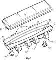
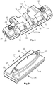
- Figs. 1 to 3 show a first embodiment of a track link 4 according to the invention with a wear pad 1 attached directly to track link 4 without an intermediate plate 6, in a perspective view.
- Fastening means 26 and fastening holes 20 coaxial with this for fastening screws 28 for fastening the exchangeable wear pad 1 on the track link 4 adapted to the wear pad 1 are provided in the wear pad 1.
- the crawler track link 4 has through holes 32, which are arranged coaxially to the fastening holes 20 of the wear pad 1, for receiving the fastening screws 28.
- the fastening means 26 are preferably arranged in the longitudinal direction of the wear pad 1 and preferably in the region of the free ends.
- the crawler links 4 require according to Fig. 10 no intermediate plate 6 and are articulated via bearing eyes 50, 52 with each other, the bearing eyes 50 engage in the bearing eyes 52 of an adjacent track link 4 and there, for. B. via a not shown Bearing bolts are articulated together.
- the wear pad 1 is preferably fastened to the track link 4 with only two fastening screws 28.
- Figs. 1 and 3 shows a wear pad 1 with a projection 30 with an outer contour which is curved in plan view and which can also be made essentially elliptical.
- the wear pads 1 of all embodiments preferably consist of an optionally reinforced wear pad material 36, preferably an elastomer material, e.g. B. polyurethane, which, according to a particularly preferred embodiment, is colored through with a light luminous color, preferably signal yellow (RAL 1003).
- an elastomer material e.g. B. polyurethane
- a light luminous color preferably signal yellow (RAL 1003).
- the projection 30 counteracts Fig. 2 does not have to end flush with the front edges of the wear pad 1 in the longitudinal direction 34, but can also end just behind the fastening holes 20.
- the wear pad 1 can preferably have cast-in reinforcing elements 18, which preferably run in the longitudinal direction 34 of the wear pad 1.
- only one reinforcement element 18 is arranged in the wear pad 1.
- fastening means 26 can be anchored, which cooperate with fastening screws 28 through the through bores 20 of the reinforcement element 18.
- the fastening means 26 can alternatively also consist of screw bolts protruding with respect to the wear pad 1, which are screwed onto the inside of a crawler link 4 with a nut.
- the wear pads 1 have a running surface 14 on their outside, as well as an underside 16 facing the track link 4, which runs essentially parallel to the running surface 14.
- the fastening means 26 are suitable for receiving fastening screws 28 that can be screwed in from the underside 16 of the wear pad 1.
- the track links 4 have suitable through bores 32 which run coaxially to the fastening holes 20 and the fastening means 26 of the wear pad 1. It is essential that at least a part 22 of the reinforcing element 18 rests directly on the track link 4 in the assembled state of the wear pad 1 or is flush with the wear pad material 36.
- the reinforcing element 18 in the wear pad 1, e.g. B. in the form of a reinforcement rail, runs in the first and all further exemplary embodiments in at least one projection 30 protruding from the underside 16 on the underside 16 of the wear pad 1.
- the reinforcing element 18 is preferably only provided in the longitudinally extending projection 30 and can follow its contour, in the sense that the reinforcing element 18 is essentially adapted to the outer contour of the projection 30 in the longitudinal direction 34. If possible, as for example in the embodiment of Figs. 1 to 3 6, 6, the reinforcing element 18 can also run essentially in a straight line in the longitudinal direction 34.
- the reinforcement element 18 itself can also form part of the projection 30.
- the projection 30 z. B. can also be divided into two or more projections 30 in the longitudinal direction 34, or that two projections 30 run essentially parallel to one another on the underside 16 of the wear pad 1.
- Fig. 4 shows a perspective view of a wear pad 1 with a projection 30 which is wave-shaped in plan view and protrudes from the underside 16 of the wear pad.
- the underside 16 rests on the track link 4, the projection 30 engaging in a corresponding recess 38 of the track link 4.
- the respective recess 38 of the crawler link 4 is the respective contour and shape of the projections 30, as they are from the Figs. 1 to 5 can be seen, adjusted.
- the projection 30 is at least partially in engagement with the recess 38 in such a way that there is a form fit at least in the longitudinal direction 34 of the wear pad 1. This does not require that the projection 30 completely match the contour of the recess 38.
- the projection 30 is designed to be complementary to the recess 38 of the track link 4.
- the reinforcing element 18 of Fig. 5 can also have a recess corresponding to the recess 46, into which the preferably complementary projection of the track link 4 can engage with exclusively metallic contact, if necessary.
- the fastening holes 20 of the wear pad 1 are coaxial with the through bores 32 of the track link.
- the reinforcement element 18 terminates essentially flush with the wear pad material 36 at at least two points spaced apart in the longitudinal direction 34.
- the part 22 of the reinforcement element 18, which is essentially flush with the wear pad material 36, is preferably coaxial with the fastening hole 20 of the wear pad 1.
- Fig. 6 shows a longitudinal section in the longitudinal direction 34 through the wear pad and the reinforcement element 18 integrated in the projection 30.
- Fig. 7 shows a possible embodiment of an anti-twist device for the fastening means 26, which can be received sunk in the reinforcing element 18.
- the fastening means 26 can also be integral with the reinforcing element 18, or on this z. B. be attached by a non-releasable connection.
- a protective cap 40 is preferably seated on the fastening means 26, which on the one hand creates a clearance for the free end of the fastening screw 28 when the reinforcement element is cast with the wear pad material 36 and prevents wear pad material 36 from penetrating the thread of the fastening means 26.
- the fastening means 26 can also consist of a cap nut or a rivet nut.
- the part 22 of the reinforcing element 18 which is in contact with the track link 4 is designed as an annular collar coaxial with the fastening hole 20.
- the replaceable wear pads 1 according to the prior art are, as from Fig. 10 can be seen, releasably fastened via an intermediate plate 6 on chain links 3 of the endlessly rotating crawler belt 2, which are coupled to one another in an articulated manner.
- Fig. 10 shows a wear pad 1 according to the prior art in a perspective view with the intermediate plate 6 underneath, which in turn is fastened to the chain links 3.
- a total of four fastening screws 24 are used to fasten the wear pad 1 on the intermediate plate 6 and another four fastening screws 27 are screwed through through holes 35 of the intermediate plate 6 and through holes 33 with two chain links 3 running parallel to one another.
- Figs. 1 to 8 do not require an intermediate plate 6 and can be fastened in this way with just two fastening screws 28 that the screw connections are largely relieved of transverse forces.
- the crawler belt 2 of the embodiments of Figs. 1 to 8 corresponds to the representation of Fig. 9 with the exception that the intermediate plate 6 and the chain links 3 are replaced by track links 4.
Landscapes
- Engineering & Computer Science (AREA)
- Chemical & Material Sciences (AREA)
- Combustion & Propulsion (AREA)
- Transportation (AREA)
- Mechanical Engineering (AREA)
- Railway Tracks (AREA)
- Devices For Conveying Motion By Means Of Endless Flexible Members (AREA)
- Body Structure For Vehicles (AREA)
- Road Repair (AREA)
- Component Parts Of Construction Machinery (AREA)
Description
Die Erfindung betrifft ein auswechselbares Verschleißpolster für eine Gleiskette eines Kettenfahrzeugs, nach dem Oberbegriff des Anspruchs 1.The invention relates to an exchangeable wear pad for a crawler belt of a tracked vehicle, according to the preamble of
Aus dem Stand der Technik sind auswechselbare Verschleißpolster für Gleisketten bekannt, die an einer Zwischenplatte der Gleiskette lösbar befestigt werden können.Exchangeable wear pads for crawlers are known from the prior art, which can be releasably attached to an intermediate plate of the crawler.
Die Verschleißpolster weisen in der Regel vier in Längsrichtung des Verschleißpolsters beabstandete nach außen vorstehende Schraubbolzen von Befestigungsschrauben auf. Die Befestigungsschrauben sind durch Verstärkungsschienen hindurchgeführt und in geeigneter Weise gegen Verdrehen gesichert.The wear pads generally have four outwardly protruding screw bolts of fastening screws that are spaced apart in the longitudinal direction of the wear pad. The fastening screws are passed through reinforcement rails and secured against twisting in a suitable manner.
Bei der Herstellung dieser Verschleißpolster werden die Verstärkungsschienen mit an ihren Enden angeordneten Befestigungsschrauben von dem Verschleißpolstermaterial umgossen.During the manufacture of these wear pads, the reinforcement rails are encased by the wear pad material with fastening screws arranged at their ends.
Nachteilig ist dabei, dass sich das Verschleißpolstermaterial beim Umgießen auch unter die Verstärkungsschiene setzt. Dies hat den Nachteil, dass sich die Verschraubungen mit einer Zwischenplatte während des Betriebs aufgrund des weichen Polyurethanmaterials zwischen Verstärkungsschiene und Zwischenplatte wieder lösen, so dass die Schraubverbindungen regelmäßig nachgezogen werden müssen. Das zwischen der Verstärkungsschiene und der Zwischenplatte befindliche Polyurethanmaterial verhindert nämlich, dass die Vorspannung der Schraubenverbindung dauerhaft aufrechterhalten bleiben kann. Es versteht sich, dass bei bis zu 50 Verschleißpolstern je Gleiskette eines Fahrwerks und bei vier Fahrwerken je Maschine der zeitliche Aufwand für das Nachspannen der Schraubverbindungen erheblich ist, so dass erhöhte Kosten und ein erhöhter Zeitbedarf entsteht.The disadvantage here is that the wear pad material also settles under the reinforcement rail when it is cast around. This has the disadvantage that the screw connections with an intermediate plate loosen again during operation due to the soft polyurethane material between the reinforcement rail and the intermediate plate, so that the screw connections have to be retightened regularly. The polyurethane material located between the reinforcement rail and the intermediate plate prevents the pre-tensioning of the screw connection from being permanently maintained. It goes without saying that with up to 50 wear pads per crawler track of a chassis and with four chassis per machine, the time required for retensioning the screw connections is considerable, so that increased costs and an increased time requirement arise.
Aus der
Auch eine Schräglage der Baumaschine erzeugt hohe Querkräfte, die von den Befestigungsmitteln des Verschleißpolsters und den Befestigungsmitteln der Zwischenplatte aufgenommen werden müssen.An inclined position of the construction machine also generates high transverse forces which have to be absorbed by the fastening means of the wear pad and the fastening means of the intermediate plate.
Der Erfindung liegt daher die Aufgabe zugrunde, ein Verschleißpolster für eine Gleiskette der eingangs genannten Art, sowie eine Gleiskette und eine Baumaschine zu schaffen, mit denen die Haltbarkeit der Schraubverbindungen, eines Verschleißpolsters verbessert und die Herstellungskosten, und der Zeitaufwand für die Montage bzw. Demontage der Verschleißpolster und damit die Wartungskosten verringert werden können.The invention is therefore based on the object of creating a wear pad for a track of the type mentioned, as well as a track and a construction machine, with which the durability of the screw connections, a wear pad and the manufacturing costs and the time required for assembly and disassembly are improved the wear pad and thus the maintenance costs can be reduced.
Diese Aufgabe wird durch die Merkmale von Anspruch 1 gelöst.This object is achieved by the features of
Die Erfindung sieht in vorteilhafter Weise vor, dass der Vorsprung des Verschleißpolsters auf der dem Gleiskettenglied zugewandten Unterseite für den zumindest teilweisen Eingriff in eine an den Vorsprung angepasste Vertiefung des Gleiskettengliedes eine Außenkontur aufweist, die zumindest teilweise unter einem zur Längsrichtung des Verschleißpolsters abweichenden Winkel verläuft.The invention advantageously provides that the projection of the wear pad on the underside facing the track link for at least partial engagement in a recess of the track link adapted to the protrusion has an outer contour that runs at least partially at an angle deviating from the longitudinal direction of the wear pad.
Dadurch, dass der Vorsprung des Verschleißpolsters zumindest teilweise im Eingriff ist mit einer an dem Vorsprung angepassten Vertiefung des Gleiskettengliedes, können Querkräfte aufgenommen werden, die insbesondere beim Lenken des Kettenfahrzeugs in Längsrichtung des Verschleißpolsters wirken. Die Lenckräfte und/oder Schräglage der Gleiskette quer zur Bewegungsrichtung der Gleiskette bilden eine wechselnde Belastung auf die Befestigungsmittel, so dass sich die Schraubverbindung der Verschleißpolster unter der Einwirkung von wechselnden Querkräften lockern kann und ein Nachspannen der Schraubverbindungen erfordern kann. Die Außenkontur des an der Unterseite des Verschleißpolsters vorstehenden Vorsprungs, die zumindest teilweise unter einem zur Längsrichtung des Verschleißpolsters abweichenden Winkel verläuft, nimmt die Querkräfte auf und entlastet damit die Befestigungsmittel vollständig oder zumindest in wesentlichem Umfang von der Wechselbelastung. Auf diese Weise ist es möglich, nur noch zwei gegenseitig in Längsrichtung des Verschleißpolsters beabstandete Befestigungsmittel zu verwenden, so dass der Montageaufwand für Montage und Demontage des Verschleißpolsters verringert, quasi halbiert ist, und auch die Herstellkosten für das Verschleißpolster reduziert werden.Because the projection of the wear pad is at least partially in engagement with a recess of the track link adapted to the projection, transverse forces can be absorbed, which act in particular when steering the tracked vehicle in the longitudinal direction of the wear pad. The deflection forces and / or inclination of the crawler belt transversely to the direction of movement of the crawler belt form an alternating load on the fastening means, so that the screw connection of the wear pads can loosen under the action of changing transverse forces and may require the screw connections to be retightened. The outer contour of the projection protruding on the underside of the wear pad, which extends at least partially at an angle deviating from the longitudinal direction of the wear pad, absorbs the transverse forces and thus relieves the fastening means completely or at least to a considerable extent from the alternating load. In this way, it is possible to use only two fastening means that are mutually spaced apart in the longitudinal direction of the wear pad, so that the assembly effort for mounting and dismounting of the wear pad is reduced, almost halved, and the manufacturing costs for the wear pad are also reduced.
In besonders bevorzugter Ausführungsform ist der Winkel ≠ 0° und ≠ 90°. Vorzugsweise liegt der Winkel im Bereich von 20° bis 70° und besonders bevorzugt 30° bis 60°.In a particularly preferred embodiment, the angle is ≠ 0 ° and ≠ 90 °. The angle is preferably in the range from 20 ° to 70 ° and particularly preferably 30 ° to 60 °.
Der Vorsprung weist vorzugsweise zwei sich im Wesentlichen in Längsrichtung erstreckende Seitenflächen und zwei sich vorzugsweise im Wesentlichen senkrecht zur Längsrichtung erstreckende Stirnflächen auf. Die Seitenflächen des Vorsprungs weisen hierbei zur Aufnahme von Querkräften den erfindungsgemäßen Winkel zur Längsrichtung des Verschleißpolsters auf. Die Seitenflächen können in Längsrichtung einen konstanten Abstand aufweisen und insofern parallel zueinander verlaufen. Ebenso kann der Abstand zwischen den Seitenflächen in Längsrichtung variieren.The projection preferably has two side surfaces extending substantially in the longitudinal direction and two end surfaces preferably extending substantially perpendicular to the longitudinal direction. The side surfaces of the projection here have the angle according to the invention to the longitudinal direction of the wear pad in order to absorb transverse forces. The side surfaces can have a constant distance in the longitudinal direction and thus run parallel to one another. The distance between the side surfaces can also vary in the longitudinal direction.
Ein weiterer Vorteil besteht darin, dass zwischen dem Gleiskettenglied und dem Verschleißpolster keine Zwischenplatte mehr benötigt wird. Es entfallen dadurch weitere Befestigungsmittel zwischen Gleiskette und Zwischenplatte, so dass der Montage- und Demontageaufwand insgesamt erheblich reduziert ist.Another advantage is that an intermediate plate is no longer required between the track link and the wear pad. This eliminates the need for further fastening means between the crawler belt and the intermediate plate, so that the assembly and disassembly effort is considerably reduced overall.
Besonders bevorzugt ist der Eingriff des Vorsprungs in eine zu dem Vorsprung komplementäre Vertiefung, die einen Formschluss zumindest in Längsrichtung des Verschleißpolsters bildet.Particularly preferred is the engagement of the projection in a recess which is complementary to the projection and which forms a form fit at least in the longitudinal direction of the wear pad.
Vorzugsweise ist vorgesehen, dass das Verschleißpolster mindestens ein Verstärkungselement enthält, das zumindest überwiegend von Verschleißpolstermaterial umschlossen oder umgossen ist. Das Verstärkungselement erhöht die Steifigkeit, des Verschleißpolsters insbesondere in Form einer Verstärkungsschiene und ermöglicht eine starre Befestigung an den Gleiskettengliedern, ohne dass ein Nachspannen der Befestigungsmittel vor dem vollständigem Verschleiß der Lauffläche des Verschleißpolsters notwendig wird.It is preferably provided that the wear pad contains at least one reinforcement element which is at least predominantly enclosed or encapsulated by wear pad material. The reinforcement element increases the rigidity of the wear pad, in particular in the form of a reinforcement rail and enables rigid attachment to the track links without the need to re-tension the fastening means before the running surface of the wear pad is completely worn.
Das Verschleißpolster kann mindestens zwei in Längsrichtung des Verschleißpolsters mit Abstand voneinander angeordnete Befestigungsmittel aufweisen, die zur Befestigung des Verschleißpolsters an dem Gleiskettenglied dienen. Dabei sind die Befestigungsmittel vorzugsweise in der Nähe der in Längsrichtung freien Enden des Verschleißpolsters an der Unterseite angeordnet.The wear pad can have at least two fastening means which are arranged at a distance from one another in the longitudinal direction of the wear pad and which are used to fasten the wear pad to the track link. The fastening means are preferably arranged in the vicinity of the free ends of the wear pad on the underside in the longitudinal direction.
Vorzugsweise ist vorgesehen, dass das Verstärkungselement in den mindestens einen Vorsprung des Verschleißpolsters integriert ist. Auf diese Weise bildet der nicht den Vorsprung bildende Teil des Verschleißpolsters einen Verschleißbelag, der nahezu vollständig aufgebraucht werden kann.It is preferably provided that the reinforcement element is integrated into the at least one projection of the wear pad. In this way, the part of the wear pad that does not form the projection forms a wear layer that can be almost completely used up.
Die Befestigungsmittel können in dem Verstärkungselement integriert sein und können auch einstückig mit dem Verstärkungselement sein. Derartige Befestigungsmittel ermöglichen eine sichere Befestigung des Verschleißpolsters über die gesamte Nutzungsdauer des Verschleißpolsters.The fastening means can be integrated in the reinforcement element and can also be in one piece with the reinforcement element. Such fasteners enable a secure attachment of the wear pad over the entire service life of the wear pad.
Bei einem bevorzugten Ausführungsbeispiel ist vorgesehen, dass das Verstärkungselement in Längsrichtung des Verschleißpolsters an mindestens zwei in Längsrichtung beabstandeten Stellen des im Vorsprung eingebetteten Verstärkungselementes im Wesentlichen bündig mit dem Verschleißpolstermaterial abschließt. Dadurch ist es möglich, dass beim Spannen der Befestigungsmittel das Verstärkungselement an den zwei beabstandeten Stellen in direktem Kontakt mit dem Gleiskettenglied stehen kann, so dass die Vorspannung der Schraubenverbindung dauerhaft aufrechterhalten bleibt und sich die Befestigungsmittel während der Nutzungsdauer nicht lockern.In a preferred embodiment, it is provided that the reinforcement element terminates essentially flush with the wear pad material in the longitudinal direction of the wear pad at at least two longitudinally spaced locations of the reinforcement element embedded in the projection. This makes it possible for the reinforcement element to be in direct contact with the track link at the two spaced-apart locations when the fastening means are tensioned, so that the pretensioning of the screw connection is permanently maintained and the fastening means do not loosen during the service life.
Dabei ist vorzugsweise vorgesehen, dass die mindestens zwei im Wesentlichen bündig mit dem Verschleißpolstermaterial abschließenden Stellen des im Vorsprung eingebetteten Verstärkungselementes im Bereich der Befestigungsmittel des Verstärkungselementes angeordnet sind. Dies hat den Vorteil, dass die Vorspannung, die die Befestigungsmittel aufbringen, an den mit dem Gleiskettenglied in Kontakt stehenden Stellen des Verstärkungselementes am höchsten ist.It is preferably provided that the at least two locations of the reinforcement element embedded in the projection, which are essentially flush with the wear pad material, are arranged in the area of the fastening means of the reinforcement element. This has the advantage that the prestress applied by the fastening means is highest at the points of the reinforcement element that are in contact with the track link.
Bei einem besonders bevorzugten Ausführungsbeispiel ist vorgesehen, dass das sich längserstreckende Verschleißpolster ein Verhältnis von Länge zu Breite zwischen 2,5 und 5, vorzugsweise im Bereich zwischen 3,5 und 4, aufweist. Auf diese Weise können die Lücken zwischen zwei Verschleißpolstern der Gleiskette gering gehalten werden und gleichzeitig eine größere Standfläche für die Gleiskette erzielt werden.In a particularly preferred embodiment it is provided that the longitudinally extending wear pad has a length to width ratio between 2.5 and 5, preferably in the range between 3.5 and 4. In this way, the gaps between two wear pads of the track can be kept small and at the same time a larger footprint for the track can be achieved.
Vorzugsweise ist vorgesehen, dass das Verschleißpolster zumindest an der Außenseite der Gleiskette quer zur Bewegungsrichtung gesehen gegenüber dem Gleiskettenglied übersteht. Auf diese Weise wird das Gleiskettenglied z. B. an Bordsteinkanten vor Beschädigung geschützt.It is preferably provided that the wear pad protrudes from the crawler link at least on the outside of the crawler belt, seen transversely to the direction of movement. In this way, the track link z. B. on curbs protected from damage.
Bei einem bevorzugten Ausführungsbeispiel ist das Verhältnis der Breite quer zur Längsrichtung eines Verschleißpolsters zu dem Umlenkradius der Gleiskette im Bereich zwischen 0,2 und 0,4, vorzugsweise zwischen 0,25 und 0,3. Ein derartiges Verhältnis, auch Teilungsmaß genannt, hat den Vorteil, dass die Laufruhe der Gleiskette verbessert werden kann.In a preferred embodiment, the ratio of the width transverse to the longitudinal direction of a wear pad to the deflection radius of the crawler belt is in the range between 0.2 and 0.4, preferably between 0.25 and 0.3. One of those Ratio, also called pitch, has the advantage that the smooth running of the crawler belt can be improved.
Bei einem Ausführungsbeispiel der Erfindung ist vorgesehen, dass die Vorsprünge des Verschleißpolsters bezogen auf die Längsrichtung des Verschleißpolsters nicht linear verlaufen, und zwar zumindest teilweise gebogen oder wellenförmig zur Längsrichtung des Verschleißpolsters verlaufen. Eine derartige Kontur der Vorsprünge ermöglicht einen Formschluss mit dem Gleiskettenglied, mit dem hohe Querkraftkomponenten aufgenommen werden können, die nicht ausschließlich quer zur Bewegungsrichtung des Verschleißpolsters auftreten.In one embodiment of the invention, it is provided that the projections of the wear pad do not run linearly with respect to the longitudinal direction of the wear pad, namely at least partially curved or wave-shaped to the longitudinal direction of the wear pad. Such a contour of the projections enables a form fit with the track link, with which high transverse force components can be absorbed that do not only occur transversely to the direction of movement of the wear pad.
Bei einem alternativen Ausführungsbeispiel kann vorgesehen sein, dass die Vorsprünge des Verschleißpolsters in Längsrichtung des Verschleißpolsters linear, und zwar zumindest teilweise schräg oder winkelförmig zur Längsrichtung des Verschleißpolsters verlaufen. Beispielsweise kann die Außenkontur des Vorsprungs in Längsrichtung in Draufsicht eine Zickzackform oder eine Sägezahnform aufweisen. Auch bei dieser Ausführungsform können von der Gleiskette ausgehende Querkraftkomponenten unterschiedlicher Richtungen aufgenommen werden und damit die Befestigungsmittel insbesondere von Querkräften vollständig oder zumindest in einem wesentlichen Umfang entlastet werden.In an alternative embodiment, it can be provided that the projections of the wear pad extend linearly in the longitudinal direction of the wear pad, specifically at least partially at an angle or at an angle to the longitudinal direction of the wear pad. For example, the outer contour of the projection in the longitudinal direction can have a zigzag shape or a sawtooth shape in plan view. In this embodiment too, transverse force components in different directions emanating from the crawler belt can be absorbed and the fastening means, in particular, can be relieved of transverse forces completely or at least to a substantial extent.
Desweiteren kann vorgesehen sein, dass die Vorsprünge des Verschleißpolsters in Längsrichtung des Verschleißpolsters eine unterschiedliche Breite aufweisen, oder in Längsrichtung an den Stirnseiten und/oder Außenkanten gestuft ausgebildet sind.Furthermore, it can be provided that the projections of the wear pad have a different width in the longitudinal direction of the wear pad, or are stepped in the longitudinal direction on the end faces and / or outer edges.
Besonders bevorzugt ist, dass das Material des Verschleißpolsters aus einem Elastomer, vorzugsweise einem Polyurethan, besteht, das vorzugsweise mit einer hellen Leuchtfarbe durchgefärbt ist. Aufgrund der Durchfärbung bleibt die helle Leuchtfarbe auch im Falle des Verschleißes des Verschleißpolsters erhalten.It is particularly preferred that the material of the wear pad consists of an elastomer, preferably a polyurethane, which is preferably colored through with a light luminous color. Due to the through-coloring, the bright luminous color is retained even if the wear pad wears out.
Die Erfindung betrifft ferner eine Gleiskette für Kettenfahrzeuge mit mehreren Verschleißpolstern der vorbeschriebenen Art, sowie eine Baumaschinen mit einer derartigen Gleiskette.The invention also relates to a crawler belt for tracked vehicles with several wear pads of the type described above, as well as a construction machine with such a crawler belt.
Im Folgenden werden unter Bezugnahme auf die Zeichnungen Ausführungsbeispiele der Erfindung näher erläutert.In the following, exemplary embodiments of the invention are explained in more detail with reference to the drawings.
Es zeigen:
- Fig. 1
- eine Explosionsdarstellung eines ersten Ausführungsbeispiels eines erfindungsgemäßen Verschleißpolsters und eines zugehörigen Gleiskettengliedes einer Gleiskette,
- Fig. 2
- eine perspektivische Darstellung eines Gleiskettengliedes von der Innenseite mit einem erfindungsgemäße Verschleißpolster,
- Fig. 3
- eine perspektivische Darstellung der Unterseite des ersten Ausführungsbeispiels eines Verschleißpolsters,
- Fig. 4
- eine Draufsicht auf die Unterseite eines zweiten Ausführungsbeispiels,
- Fig. 5
- eine Draufsicht auf die Unterseite eines dritten Ausführungsbeispiels,
- Fig. 6
- einen Schnitt durch einen Vorsprung mit integriertem Verstärkungselement,
- Fig. 7
- ein Ausführungsbeispiel für ein in dem Verstärkungselement aufgenommenes Befestigungsmittel,
- Fig. 8
- eine vergrößerte Darstellung eines Details aus
Fig. 6 , - Fig. 9
- eine Gleiskette mit Verschleißpolstern in perspektivischer Ansicht, und
- Fig. 10
- eine Explosionszeichnung eines Gleiskettengliedes mit Verschleißpolster und Zwischenplatte nach dem Stand der Technik.
- Fig. 1
- an exploded view of a first embodiment of a wear pad according to the invention and an associated track link of a track,
- Fig. 2
- a perspective view of a track link from the inside with a wear pad according to the invention,
- Fig. 3
- a perspective view of the underside of the first embodiment of a wear pad,
- Fig. 4
- a plan view of the underside of a second embodiment,
- Fig. 5
- a plan view of the underside of a third embodiment,
- Fig. 6
- a section through a projection with an integrated reinforcement element,
- Fig. 7
- an embodiment for a fastening means received in the reinforcement element,
- Fig. 8
- an enlarged view of a detail
Fig. 6 , - Fig. 9
- a crawler belt with wear pads in a perspective view, and
- Fig. 10
- an exploded view of a track link with wear pad and intermediate plate according to the prior art.
Die Gleiskette 2 läuft mit ihren Kettengliedern 3 bzw. Gleiskettengliedern 4 um zwei Umlenkrollen 8 und 10 um, von denen eine angetrieben ist. Der Umlenkradius r bemisst sich am Außenradius der Gleiskette 2, der in etwa der halben Höhe der Gleiskette 2 entspricht. Das Verhältnis der Breite des Verschleißpolsters 1 in Bewegungsrichtung 44 zu dem Umlenkradius r liegt im Bereich zwischen 0,2 und 0,4, vorzugsweise zwischen 0,25 und 0,3. Die Höhe der Gleiskette beträgt beispielsweise c.a 600 mm.The
Ein solches Teilungsmaß verbessert die Laufruhe der Gleiskette 2. Dabei liegt das Verhältnis von Länge zu Breite des Verschleißpolsters 1 im Bereich zwischen 2,5 und 5, vorzugsweise im Bereich zwischen 3,5 und 4. Die Länge des Verschleißpolsters 1 beträgt beispielsweise ca. 300 mm, die Breite ca. 80 mm.Such a pitch improves the smoothness of the
Im unteren Trum der Gleiskette 2 sind mehrere Stützrollen 12 angeordnet, die das Maschinengewicht tragen und auf den Kettengliedern 3 ablaufen.In the lower run of the
Die
Die Gleiskettenglieder 4 benötigen im Unterschied zum Stand der Technik gemäß
Das Ausführungsbeispiel der
Die Verschleißpolster 1 aller Ausführungsbeispiele bestehen vorzugsweise aus einem ggf. verstärkten Verschleißpolstermaterial 36, vorzugsweise einem Elastomermaterial, z. B. Polyurethan, das nach einem besonders bevorzugten Ausführungsbeispiel mit einer hellen Leuchtfarbe, vorzugsweise signalgelb (RAL 1003) durchgefärbt ist.The
Es versteht sich auch, dass der Vorsprung 30 entgegen
Das Verschleißpolster 1 kann vorzugsweise eingegossene Verstärkungselemente 18 aufweisen, die bevorzugt in Längsrichtung 34 des Verschleißpolsters 1 verlaufen. In dem ersten Ausführungsbeispiel ist lediglich ein Verstärkungselement 18 in dem Verschleißpolster 1 angeordnet. In der Nähe der freien Enden eines Verstärkungselementes 18 können Befestigungsmittel 26 verankert sein, die durch die Durchgangsbohrungen 20 des Verstärkungselementes 18 hindurch mit Befestigungsschrauben 28 zusammenwirken. Es versteht sich, dass die Befestigungsmittel 26 alternativ auch aus gegenüber dem Verschleißpolster 1 vorstehenden Schraubbolzen bestehen können, die auf der Innenseite eines Gleiskettengliedes 4 mit einer Mutter verschraubt werden.The
Die Verschleißpolster 1 haben auf ihrer Außenseite eine Lauffläche 14 , sowie eine dem Gleiskettenglied 4 zugewandte Unterseite 16, die im Wesentlichen parallel zur Lauffläche 14 verläuft.The
Die Befestigungsmittel 26 sind geeignet, von der Unterseite 16 des Verschleißpolsters 1 her einschraubbare Befestigungsschrauben 28 aufzunehmen. Hierzu weisen die Gleiskettenglieder 4 geeignete Durchgangsbohrungen 32 auf, die koaxial zu den Befestigungslöchern 20 und den Befestigungsmitteln 26 des Verschleißpolsters 1 verlaufen. Wesentlich ist dabei, dass zumindest ein Teil 22 des Verstärkungselementes 18 im montierten Zustand der Verschleißpolster 1 auf dem Gleiskettenglied 4 unmittelbar aufliegt oder bündig mit dem Verschleißpolstermaterial 36 abschließt.The fastening means 26 are suitable for receiving
Das Verstärkungselement 18 in dem Verschleißpolster 1 , z. B. in Form einer Verstärkungsschiene, verläuft in dem ersten und allen weiteren Ausführungsbeispielen in mindestens einem an der Unterseite 16 des Verschleißpolsters 1 von der Unterseite 16 abstehenden Vorsprung 30.The reinforcing
Dabei ist das Verstärkungselement 18 vorzugsweise nur in dem sich längserstreckenden Vorsprung 30 vorgesehen und kann dessen Kontur folgen, in dem Sinne, dass das Verstärkungselement 18 der Außenkontur des Vorsprungs 30 in Längsrichtung 34 im Wesentlichen angepasst ist. Sofern möglich, wie beispielsweise bei dem Ausführungsbeispiel der
Es versteht sich, dass der Vorsprung 30 z. B. auch in Längsrichtung 34 in zwei oder mehr Vorsprünge 30 aufgeteilt sein kann, oder dass zwei Vorsprünge 30 im Wesentlichen parallel zueinander an der Unterseite 16 des Verschleißpolsters 1 verlaufen.It is understood that the projection 30 z. B. can also be divided into two or
Die jeweilige Vertiefung 38 des Gleiskettengliedes 4 ist der jeweiligen Kontur und Form der Vorsprünge 30, wie sie aus den
Es versteht sich, dass der Vorsprung 30 zumindest teilweise in Eingriff mit der Vertiefung 38, in der Art ist, dass zumindest in Längsrichtung 34 des Verschleißpolsters 1 ein Formschluss besteht. Dies erfordert nicht, dass der Vorsprung 30 vollständig mit der Kontur der Vertiefung 38 übereinstimmt. Vorzugsweise ist jedoch der Vorsprung 30 komplementär zu der Vertiefung 38 des Gleiskettengliedes 4 ausgebildet.It goes without saying that the
Bei dem Ausführungsbeispiel der
Es versteht sich dabei, dass das Verstärkungselement 18 der
Die Befestigungslöcher 20 des Verschleißpolsters 1 sind koaxial zu den Durchgangsbohrungen 32 des Gleiskettengliedes.The fastening holes 20 of the
Das Verstärkungselement 18 schließt in Längsrichtung 34 des Verschleißpolsters an mindestens zwei in Längsrichtung 34 beabstandeten Stellen im Wesentlichen bündig mit dem Verschleißpolstermaterial 36 ab. Vorzugsweise ist der Teil 22 des Verstärkungselementes 18, der im Wesentlichen bündig mit dem Verschleißpolstermaterial 36 abschließt, koaxial zu dem Befestigungsloch 20 des Verschleißpolsters 1.In the
Das Befestigungsmittel 26 kann auch einstückig mit dem Verstärkungselement 18 sein, oder an diesem z. B. durch eine nicht lösbare Verbindung befestigt sein.The fastening means 26 can also be integral with the reinforcing
Vorzugsweise sitzt auf dem Befestigungsmittel 26 eine Schutzkappe 40 , die einerseits beim Vergießen des Verstärkungselementes mit dem Verschleißpolstermaterial 36 einen Freiraum für das freie Ende der Befestigungsschraube 28 schafft und verhindert, dass Verschleißpolstermaterial 36 in das Gewinde des Befestigungsmittels 26 eindringen kann. Alternativ kann das Befestigungsmittel 26 auch aus einer Hutmutter oder einer Nietmutter bestehen.A
Bei diesem Ausführungsbeispiel ist der mit dem Gleiskettenglied 4 in Kontakt befindliche Teil 22 des Verstärkungselementes 18 als zu dem Befestigungsloch 20 koaxialer Ringbund ausgeführt.In this embodiment, the
Es ist allerdings nicht zwingend erforderlich, dass der Teil 22 des Verstärkungselementes das Befestigungsloch 20 vollständig umgibt.However, it is not absolutely necessary for the
Die auswechselbaren Verschleißpolster 1 nach dem Stand der Technik sind, wie aus
Sämtliche bei dem Stand der Technik auftretenden Querkräfte werden von den insgesamt 8 Befestigungsschrauben 24, 27 aufgefangen und belasten dementsprechend die Schraubverbindungen.All of the transverse forces occurring in the prior art are absorbed by the total of 8 fastening screws 24, 27 and accordingly stress the screw connections.
Die Ausführungsbeispiele der
Die Gleiskette 2 der Ausführungsbeispiele der
Claims (15)
- Wear pad for a crawler track (2) of a tracked vehicle, wherein- the wear pad (1) comprises an outer tread surface (14), and a bottom side (16) opposite the tread surface (14) from which at least one protrusion (30) protrudes,- the wear pad (1) comprises fastening means (26) for fastening to the crawler track (2),- the wear pad material (36) of the wear pad (1) is made of an elastomer, preferably a polyurethane,- the wear pad (1) includes, as a minimum, one reinforcing element (18), at least the major part of which is enclosed or cast in by wear pad material (36),characterized in that
the protrusion of the wear pad (1) comprises, on the bottom side (16) facing a crawler track link (4) of the crawler track (2), for the at least partial engagement with an indentation of the crawler track link (4) adapted to the protrusion, a contour which extends, at least partially, at an angle deviating from the longitudinal direction (34) of the wear pad (1). - Wear pad in accordance with claim 1, characterized in that the wear pad (1) comprises at least two fastening means (26) arranged at a distance to one another in the longitudinal direction of the wear pad (1).
- Wear pad in accordance with claim 1 or 2, characterized in that the reinforcing element (18) is, at least partially, integrated in the at least one protrusion (30) of the wear pad (1).
- Wear pad in accordance with one of the claims 1 to 3, characterized in that the fastening means (26) are integrated in the reinforcing element (18), and are preferably of integral design with the reinforcing element (18).
- Wear pad in accordance with one of the claims 1 to 4, characterized in that, in the longitudinal direction (34) of the wear pad (1), the reinforcing element (18) terminates essentially flush with the wear pad material (36) in at least two points, spaced in the longitudinal direction (34), of the reinforcing element (18) otherwise embedded in the protrusion (30).
- Wear pad in accordance with one of the claims 4 or 5, characterized in that the at least two points of the reinforcing element (18) embedded in the protrusion (30) that terminate essentially flush with the wear pad material (36) are arranged in the area of the fastening means (22) of the reinforcing element (18).
- Wear pad in accordance with one of the claims 1 to 6, characterized in that the longitudinally extending wear pad (1) comprises a length-to-width ratio in the range between 2.5 and 5.0, preferably in the range between 3.5 and 4.0.
- Wear pad in accordance with one of the claims 1 to 7, characterized in that the wear pad (1) protrudes vis-à-vis the crawler track (2) at least on the outer side (42) of the crawler track (2) as seen transverse to the direction of movement (44).
- Wear pad in accordance with one of the claims 1 to 8, characterized in that the ratio of the width transverse to the longitudinal direction (34) of a wear pad (1) to the return radius (r) of the crawler track (2) is in the range between 0.2 and 0.4, preferably between 0.25 and 3.
- Wear pad in accordance with one of the claims 1 to 9, characterized in that the at least one protrusion (30) of the wear pad (1) extends, at least in part, non-linearly in the longitudinal direction (34) of the wear pad (1), in particular, in part, in a curved or undulating fashion relative to the longitudinal direction of the wear pad (1).
- Wear pad in accordance with one of the claims 1 to 9, characterized in that the at least one protrusion (30) of the wear pad (1) extends, at least in part, linearly in the longitudinal direction (34) of the wear pad (1), in particular, in part, in an oblique or angular fashion relative to the longitudinal direction (34) of the wear pad (1).
- Wear pad in accordance with one of the claims 1 to 11, characterized in that the at least one protrusion (30) of the wear pad (1) exhibits a different width in the longitudinal direction (34) of the wear pad (1) or is of stepped design in the cross section.
- Wear pad in accordance with one of the claims 1 to 12, characterized in that the wear pad material is through-coloured in a bright fluorescent colour.
- Crawler track (2) for tracked vehicles, in particular for milling machines, comprising multiple crawler track links (4) continuously revolving in the direction of movement, coupled to one another in an articulated fashion, on the outer side of which at least one wear pad (1) each in accordance with one of the claims 1 to 13 is fastened.
- Construction machine, in particular milling machine, comprising at least one crawler track (2) in accordance with claim 14.
Applications Claiming Priority (2)
| Application Number | Priority Date | Filing Date | Title |
|---|---|---|---|
| DE102016202626.7A DE102016202626A1 (en) | 2016-02-19 | 2016-02-19 | Wear pad for a crawler track of a tracked vehicle, crawler and construction machine |
| PCT/EP2017/053236 WO2017140652A1 (en) | 2016-02-19 | 2017-02-14 | Wear pad for a track of a tracked vehicle, track, and construction machine |
Publications (2)
| Publication Number | Publication Date |
|---|---|
| EP3416876A1 EP3416876A1 (en) | 2018-12-26 |
| EP3416876B1 true EP3416876B1 (en) | 2020-11-18 |
Family
ID=58018123
Family Applications (1)
| Application Number | Title | Priority Date | Filing Date |
|---|---|---|---|
| EP17704774.3A Active EP3416876B1 (en) | 2016-02-19 | 2017-02-14 | Wear pad for a track of a tracked vehicle, track, and construction machine |
Country Status (6)
| Country | Link |
|---|---|
| US (1) | US11097795B2 (en) |
| EP (1) | EP3416876B1 (en) |
| CN (2) | CN107097863B (en) |
| DE (1) | DE102016202626A1 (en) |
| TW (1) | TWI643778B (en) |
| WO (1) | WO2017140652A1 (en) |
Families Citing this family (2)
| Publication number | Priority date | Publication date | Assignee | Title |
|---|---|---|---|---|
| DE102016202626A1 (en) * | 2016-02-19 | 2017-08-24 | Wirtgen Gmbh | Wear pad for a crawler track of a tracked vehicle, crawler and construction machine |
| US20220089233A1 (en) * | 2020-09-24 | 2022-03-24 | General Dynamics Land Systems | Endless track for a track laying vehicle having a shoe assembly with a composite track shoe |
Family Cites Families (16)
| Publication number | Priority date | Publication date | Assignee | Title |
|---|---|---|---|---|
| US1786924A (en) * | 1927-06-08 | 1930-12-30 | Caterpillar Tractor Co | Track shoe |
| US1835627A (en) * | 1928-04-02 | 1931-12-08 | Kensington Steel Company | Link belt tread for vehicles |
| US3475060A (en) | 1968-06-04 | 1969-10-28 | Us Army | Self-cleaning track snow pad for track laying vehicles |
| JPS58101880A (en) | 1981-12-10 | 1983-06-17 | Mitsubishi Steel Mfg Co Ltd | Triangular shoe plate or flat shoe plate for endless track band and its manufacturing method |
| JP2601477Y2 (en) | 1990-09-21 | 1999-11-22 | 株式会社小松製作所 | Rubber tracks interchangeable with iron tracks |
| US5353029A (en) * | 1993-05-17 | 1994-10-04 | Johnston Beverly R | Separable electromagnetic waveguide attenuator |
| US5630657A (en) * | 1993-11-20 | 1997-05-20 | Bridgestone Corporation | Crawler |
| EP0761525B1 (en) * | 1994-06-01 | 1999-08-11 | Komatsu Ltd. | Elastic-bodied crawler plate and crawler band |
| DE102006043763C5 (en) | 2006-09-13 | 2020-07-16 | Wirtgen Gmbh | Interchangeable wear pads and track chain |
| US8011739B2 (en) * | 2006-09-13 | 2011-09-06 | Wirtgen Gmbh | Replaceable wear pad |
| JP5284649B2 (en) * | 2008-01-22 | 2013-09-11 | 住友ゴム工業株式会社 | Method for manufacturing elastic pad and elastic pad |
| RU2443589C1 (en) | 2010-07-02 | 2012-02-27 | Общество С Ограниченной Ответственностью "Смарт" (Ооо "Смарт") | Caterpillar track of mine hydraulic excavator |
| EP2588362B1 (en) | 2011-09-13 | 2016-07-13 | Liebherr-Mining Equipment Colmar SAS | Track pad |
| DE202014102210U1 (en) * | 2014-05-12 | 2014-07-11 | Hans Hall Gmbh | crawler web |
| CN204713230U (en) * | 2015-05-11 | 2015-10-21 | 徐州市耐力高分子科技有限公司 | Grooved skeleton crawler shoe and caterpillar block |
| DE102016202626A1 (en) | 2016-02-19 | 2017-08-24 | Wirtgen Gmbh | Wear pad for a crawler track of a tracked vehicle, crawler and construction machine |
-
2016
- 2016-02-19 DE DE102016202626.7A patent/DE102016202626A1/en not_active Withdrawn
-
2017
- 2017-02-14 WO PCT/EP2017/053236 patent/WO2017140652A1/en active Application Filing
- 2017-02-14 EP EP17704774.3A patent/EP3416876B1/en active Active
- 2017-02-14 US US15/999,533 patent/US11097795B2/en active Active
- 2017-02-18 TW TW106105410A patent/TWI643778B/en active
- 2017-02-20 CN CN201710090796.8A patent/CN107097863B/en active Active
- 2017-02-20 CN CN201720151036.9U patent/CN206561891U/en active Active
Non-Patent Citations (1)
| Title |
|---|
| None * |
Also Published As
| Publication number | Publication date |
|---|---|
| US11097795B2 (en) | 2021-08-24 |
| TW201736170A (en) | 2017-10-16 |
| DE102016202626A1 (en) | 2017-08-24 |
| CN206561891U (en) | 2017-10-17 |
| EP3416876A1 (en) | 2018-12-26 |
| TWI643778B (en) | 2018-12-11 |
| CN107097863A (en) | 2017-08-29 |
| CN107097863B (en) | 2019-07-05 |
| US20190337580A1 (en) | 2019-11-07 |
| WO2017140652A1 (en) | 2017-08-24 |
Similar Documents
| Publication | Publication Date | Title |
|---|---|---|
| EP1900621B1 (en) | Replaceable track pad and method for manufacturing track pads for a crawler | |
| EP0922629B1 (en) | Lug for track of tracked vehicle, particularly for piste preparing or snow-track making machines. | |
| CH636812A5 (en) | TRACK CHAIN, ESPECIALLY FOR ARMORED VEHICLES. | |
| EP3416876B1 (en) | Wear pad for a track of a tracked vehicle, track, and construction machine | |
| EP1033442B1 (en) | Device for bridging expansion joints in roadways | |
| EP2918482B1 (en) | Traction chain for a track chain of a tracked vehicle and kit for a track chain | |
| DE3016151C2 (en) | Attachment of drivers to one or more round steel chains | |
| DE2914127C2 (en) | Chain wheel, in particular drive wheel for caterpillar vehicles | |
| EP0085300A2 (en) | Track section for endless track vehicle | |
| AT524130A4 (en) | climbing aid | |
| DE19856338B4 (en) | Scraper for conveyor belts | |
| DE102015208614B3 (en) | Caterpillar for a piste grooming vehicle and piste grooming vehicle with a track drive and working method of a track drive of a piste grooming vehicle | |
| EP0362326A1 (en) | Tracklaying vehicle. | |
| DE3802914C2 (en) | ||
| DE1800353A1 (en) | Crawler belt for snow vehicles | |
| EP0115570B1 (en) | Track link for all-terrain vehicle | |
| DE3400702C2 (en) | ||
| EP4088994B1 (en) | Antiskid device | |
| DE4333262C1 (en) | Stud link for tyre chains | |
| DE3510350C2 (en) | Track bracket for chains of snow groomers | |
| DE4028238C2 (en) | Flexible band-shaped tension member for track vehicles | |
| AT141929B (en) | Treadmill for tracked vehicles. | |
| DE19801917C1 (en) | Support beam for sliding chain | |
| DE19801928C1 (en) | Cover cushion for escalator chain tread | |
| DE19520375C2 (en) | Form plate for the formation of molds for abrasive materials |
Legal Events
| Date | Code | Title | Description |
|---|---|---|---|
| STAA | Information on the status of an ep patent application or granted ep patent |
Free format text: STATUS: UNKNOWN |
|
| STAA | Information on the status of an ep patent application or granted ep patent |
Free format text: STATUS: THE INTERNATIONAL PUBLICATION HAS BEEN MADE |
|
| PUAI | Public reference made under article 153(3) epc to a published international application that has entered the european phase |
Free format text: ORIGINAL CODE: 0009012 |
|
| STAA | Information on the status of an ep patent application or granted ep patent |
Free format text: STATUS: REQUEST FOR EXAMINATION WAS MADE |
|
| 17P | Request for examination filed |
Effective date: 20180831 |
|
| AK | Designated contracting states |
Kind code of ref document: A1 Designated state(s): AL AT BE BG CH CY CZ DE DK EE ES FI FR GB GR HR HU IE IS IT LI LT LU LV MC MK MT NL NO PL PT RO RS SE SI SK SM TR |
|
| AX | Request for extension of the european patent |
Extension state: BA ME |
|
| DAV | Request for validation of the european patent (deleted) | ||
| DAX | Request for extension of the european patent (deleted) | ||
| GRAP | Despatch of communication of intention to grant a patent |
Free format text: ORIGINAL CODE: EPIDOSNIGR1 |
|
| STAA | Information on the status of an ep patent application or granted ep patent |
Free format text: STATUS: GRANT OF PATENT IS INTENDED |
|
| INTG | Intention to grant announced |
Effective date: 20200717 |
|
| GRAS | Grant fee paid |
Free format text: ORIGINAL CODE: EPIDOSNIGR3 |
|
| GRAA | (expected) grant |
Free format text: ORIGINAL CODE: 0009210 |
|
| STAA | Information on the status of an ep patent application or granted ep patent |
Free format text: STATUS: THE PATENT HAS BEEN GRANTED |
|
| AK | Designated contracting states |
Kind code of ref document: B1 Designated state(s): AL AT BE BG CH CY CZ DE DK EE ES FI FR GB GR HR HU IE IS IT LI LT LU LV MC MK MT NL NO PL PT RO RS SE SI SK SM TR |
|
| REG | Reference to a national code |
Ref country code: GB Ref legal event code: FG4D Free format text: NOT ENGLISH |
|
| REG | Reference to a national code |
Ref country code: CH Ref legal event code: EP |
|
| REG | Reference to a national code |
Ref country code: IE Ref legal event code: FG4D Free format text: LANGUAGE OF EP DOCUMENT: GERMAN |
|
| REG | Reference to a national code |
Ref country code: DE Ref legal event code: R096 Ref document number: 502017008247 Country of ref document: DE |
|
| REG | Reference to a national code |
Ref country code: AT Ref legal event code: REF Ref document number: 1335471 Country of ref document: AT Kind code of ref document: T Effective date: 20201215 |
|
| REG | Reference to a national code |
Ref country code: NL Ref legal event code: MP Effective date: 20201118 |
|
| PG25 | Lapsed in a contracting state [announced via postgrant information from national office to epo] |
Ref country code: GR Free format text: LAPSE BECAUSE OF FAILURE TO SUBMIT A TRANSLATION OF THE DESCRIPTION OR TO PAY THE FEE WITHIN THE PRESCRIBED TIME-LIMIT Effective date: 20210219 Ref country code: FI Free format text: LAPSE BECAUSE OF FAILURE TO SUBMIT A TRANSLATION OF THE DESCRIPTION OR TO PAY THE FEE WITHIN THE PRESCRIBED TIME-LIMIT Effective date: 20201118 Ref country code: RS Free format text: LAPSE BECAUSE OF FAILURE TO SUBMIT A TRANSLATION OF THE DESCRIPTION OR TO PAY THE FEE WITHIN THE PRESCRIBED TIME-LIMIT Effective date: 20201118 Ref country code: PT Free format text: LAPSE BECAUSE OF FAILURE TO SUBMIT A TRANSLATION OF THE DESCRIPTION OR TO PAY THE FEE WITHIN THE PRESCRIBED TIME-LIMIT Effective date: 20210318 Ref country code: NO Free format text: LAPSE BECAUSE OF FAILURE TO SUBMIT A TRANSLATION OF THE DESCRIPTION OR TO PAY THE FEE WITHIN THE PRESCRIBED TIME-LIMIT Effective date: 20210218 |
|
| PG25 | Lapsed in a contracting state [announced via postgrant information from national office to epo] |
Ref country code: SE Free format text: LAPSE BECAUSE OF FAILURE TO SUBMIT A TRANSLATION OF THE DESCRIPTION OR TO PAY THE FEE WITHIN THE PRESCRIBED TIME-LIMIT Effective date: 20201118 Ref country code: BG Free format text: LAPSE BECAUSE OF FAILURE TO SUBMIT A TRANSLATION OF THE DESCRIPTION OR TO PAY THE FEE WITHIN THE PRESCRIBED TIME-LIMIT Effective date: 20210218 Ref country code: PL Free format text: LAPSE BECAUSE OF FAILURE TO SUBMIT A TRANSLATION OF THE DESCRIPTION OR TO PAY THE FEE WITHIN THE PRESCRIBED TIME-LIMIT Effective date: 20201118 Ref country code: LV Free format text: LAPSE BECAUSE OF FAILURE TO SUBMIT A TRANSLATION OF THE DESCRIPTION OR TO PAY THE FEE WITHIN THE PRESCRIBED TIME-LIMIT Effective date: 20201118 Ref country code: IS Free format text: LAPSE BECAUSE OF FAILURE TO SUBMIT A TRANSLATION OF THE DESCRIPTION OR TO PAY THE FEE WITHIN THE PRESCRIBED TIME-LIMIT Effective date: 20210318 |
|
| REG | Reference to a national code |
Ref country code: LT Ref legal event code: MG9D |
|
| PG25 | Lapsed in a contracting state [announced via postgrant information from national office to epo] |
Ref country code: HR Free format text: LAPSE BECAUSE OF FAILURE TO SUBMIT A TRANSLATION OF THE DESCRIPTION OR TO PAY THE FEE WITHIN THE PRESCRIBED TIME-LIMIT Effective date: 20201118 |
|
| PG25 | Lapsed in a contracting state [announced via postgrant information from national office to epo] |
Ref country code: LT Free format text: LAPSE BECAUSE OF FAILURE TO SUBMIT A TRANSLATION OF THE DESCRIPTION OR TO PAY THE FEE WITHIN THE PRESCRIBED TIME-LIMIT Effective date: 20201118 Ref country code: CZ Free format text: LAPSE BECAUSE OF FAILURE TO SUBMIT A TRANSLATION OF THE DESCRIPTION OR TO PAY THE FEE WITHIN THE PRESCRIBED TIME-LIMIT Effective date: 20201118 Ref country code: EE Free format text: LAPSE BECAUSE OF FAILURE TO SUBMIT A TRANSLATION OF THE DESCRIPTION OR TO PAY THE FEE WITHIN THE PRESCRIBED TIME-LIMIT Effective date: 20201118 Ref country code: SM Free format text: LAPSE BECAUSE OF FAILURE TO SUBMIT A TRANSLATION OF THE DESCRIPTION OR TO PAY THE FEE WITHIN THE PRESCRIBED TIME-LIMIT Effective date: 20201118 Ref country code: RO Free format text: LAPSE BECAUSE OF FAILURE TO SUBMIT A TRANSLATION OF THE DESCRIPTION OR TO PAY THE FEE WITHIN THE PRESCRIBED TIME-LIMIT Effective date: 20201118 Ref country code: SK Free format text: LAPSE BECAUSE OF FAILURE TO SUBMIT A TRANSLATION OF THE DESCRIPTION OR TO PAY THE FEE WITHIN THE PRESCRIBED TIME-LIMIT Effective date: 20201118 |
|
| REG | Reference to a national code |
Ref country code: DE Ref legal event code: R097 Ref document number: 502017008247 Country of ref document: DE |
|
| PG25 | Lapsed in a contracting state [announced via postgrant information from national office to epo] |
Ref country code: DK Free format text: LAPSE BECAUSE OF FAILURE TO SUBMIT A TRANSLATION OF THE DESCRIPTION OR TO PAY THE FEE WITHIN THE PRESCRIBED TIME-LIMIT Effective date: 20201118 |
|
| PLBE | No opposition filed within time limit |
Free format text: ORIGINAL CODE: 0009261 |
|
| STAA | Information on the status of an ep patent application or granted ep patent |
Free format text: STATUS: NO OPPOSITION FILED WITHIN TIME LIMIT |
|
| PG25 | Lapsed in a contracting state [announced via postgrant information from national office to epo] |
Ref country code: MC Free format text: LAPSE BECAUSE OF FAILURE TO SUBMIT A TRANSLATION OF THE DESCRIPTION OR TO PAY THE FEE WITHIN THE PRESCRIBED TIME-LIMIT Effective date: 20201118 |
|
| 26N | No opposition filed |
Effective date: 20210819 |
|
| REG | Reference to a national code |
Ref country code: BE Ref legal event code: MM Effective date: 20210228 |
|
| PG25 | Lapsed in a contracting state [announced via postgrant information from national office to epo] |
Ref country code: LI Free format text: LAPSE BECAUSE OF NON-PAYMENT OF DUE FEES Effective date: 20210228 Ref country code: LU Free format text: LAPSE BECAUSE OF NON-PAYMENT OF DUE FEES Effective date: 20210214 Ref country code: NL Free format text: LAPSE BECAUSE OF FAILURE TO SUBMIT A TRANSLATION OF THE DESCRIPTION OR TO PAY THE FEE WITHIN THE PRESCRIBED TIME-LIMIT Effective date: 20201118 Ref country code: CH Free format text: LAPSE BECAUSE OF NON-PAYMENT OF DUE FEES Effective date: 20210228 Ref country code: AL Free format text: LAPSE BECAUSE OF FAILURE TO SUBMIT A TRANSLATION OF THE DESCRIPTION OR TO PAY THE FEE WITHIN THE PRESCRIBED TIME-LIMIT Effective date: 20201118 |
|
| PG25 | Lapsed in a contracting state [announced via postgrant information from national office to epo] |
Ref country code: SI Free format text: LAPSE BECAUSE OF FAILURE TO SUBMIT A TRANSLATION OF THE DESCRIPTION OR TO PAY THE FEE WITHIN THE PRESCRIBED TIME-LIMIT Effective date: 20201118 |
|
| PG25 | Lapsed in a contracting state [announced via postgrant information from national office to epo] |
Ref country code: ES Free format text: LAPSE BECAUSE OF FAILURE TO SUBMIT A TRANSLATION OF THE DESCRIPTION OR TO PAY THE FEE WITHIN THE PRESCRIBED TIME-LIMIT Effective date: 20201118 Ref country code: IE Free format text: LAPSE BECAUSE OF NON-PAYMENT OF DUE FEES Effective date: 20210214 |
|
| PG25 | Lapsed in a contracting state [announced via postgrant information from national office to epo] |
Ref country code: IS Free format text: LAPSE BECAUSE OF FAILURE TO SUBMIT A TRANSLATION OF THE DESCRIPTION OR TO PAY THE FEE WITHIN THE PRESCRIBED TIME-LIMIT Effective date: 20210318 |
|
| PG25 | Lapsed in a contracting state [announced via postgrant information from national office to epo] |
Ref country code: BE Free format text: LAPSE BECAUSE OF NON-PAYMENT OF DUE FEES Effective date: 20210228 |
|
| REG | Reference to a national code |
Ref country code: AT Ref legal event code: MM01 Ref document number: 1335471 Country of ref document: AT Kind code of ref document: T Effective date: 20220214 |
|
| PG25 | Lapsed in a contracting state [announced via postgrant information from national office to epo] |
Ref country code: AT Free format text: LAPSE BECAUSE OF NON-PAYMENT OF DUE FEES Effective date: 20220214 |
|
| PGFP | Annual fee paid to national office [announced via postgrant information from national office to epo] |
Ref country code: FR Payment date: 20230220 Year of fee payment: 7 |
|
| PGFP | Annual fee paid to national office [announced via postgrant information from national office to epo] |
Ref country code: IT Payment date: 20230228 Year of fee payment: 7 |
|
| PG25 | Lapsed in a contracting state [announced via postgrant information from national office to epo] |
Ref country code: CY Free format text: LAPSE BECAUSE OF FAILURE TO SUBMIT A TRANSLATION OF THE DESCRIPTION OR TO PAY THE FEE WITHIN THE PRESCRIBED TIME-LIMIT Effective date: 20201118 |
|
| P01 | Opt-out of the competence of the unified patent court (upc) registered |
Effective date: 20230525 |
|
| PG25 | Lapsed in a contracting state [announced via postgrant information from national office to epo] |
Ref country code: HU Free format text: LAPSE BECAUSE OF FAILURE TO SUBMIT A TRANSLATION OF THE DESCRIPTION OR TO PAY THE FEE WITHIN THE PRESCRIBED TIME-LIMIT; INVALID AB INITIO Effective date: 20170214 |
|
| PG25 | Lapsed in a contracting state [announced via postgrant information from national office to epo] |
Ref country code: MK Free format text: LAPSE BECAUSE OF FAILURE TO SUBMIT A TRANSLATION OF THE DESCRIPTION OR TO PAY THE FEE WITHIN THE PRESCRIBED TIME-LIMIT Effective date: 20201118 |
|
| PGFP | Annual fee paid to national office [announced via postgrant information from national office to epo] |
Ref country code: DE Payment date: 20240216 Year of fee payment: 8 Ref country code: GB Payment date: 20240222 Year of fee payment: 8 |