EP3416716B1 - Balloon catheter - Google Patents
Balloon catheter Download PDFInfo
- Publication number
- EP3416716B1 EP3416716B1 EP17753752.9A EP17753752A EP3416716B1 EP 3416716 B1 EP3416716 B1 EP 3416716B1 EP 17753752 A EP17753752 A EP 17753752A EP 3416716 B1 EP3416716 B1 EP 3416716B1
- Authority
- EP
- European Patent Office
- Prior art keywords
- catheter
- balloon
- distal end
- adapter
- diameter
- Prior art date
- Legal status (The legal status is an assumption and is not a legal conclusion. Google has not performed a legal analysis and makes no representation as to the accuracy of the status listed.)
- Active
Links
- 239000012530 fluid Substances 0.000 claims description 74
- 238000002347 injection Methods 0.000 claims description 34
- 239000007924 injection Substances 0.000 claims description 34
- 238000004891 communication Methods 0.000 claims description 31
- 239000000463 material Substances 0.000 claims description 31
- 239000010410 layer Substances 0.000 claims description 23
- 239000002356 single layer Substances 0.000 claims description 8
- 230000003014 reinforcing effect Effects 0.000 claims description 6
- 239000012779 reinforcing material Substances 0.000 claims description 5
- 239000004033 plastic Substances 0.000 claims description 4
- 229920003023 plastic Polymers 0.000 claims description 4
- 206010028980 Neoplasm Diseases 0.000 description 19
- 238000000034 method Methods 0.000 description 18
- 230000008901 benefit Effects 0.000 description 17
- 210000004204 blood vessel Anatomy 0.000 description 14
- 239000003814 drug Substances 0.000 description 12
- 239000003795 chemical substances by application Substances 0.000 description 10
- 230000003073 embolic effect Effects 0.000 description 10
- 230000010102 embolization Effects 0.000 description 10
- 229940079593 drug Drugs 0.000 description 9
- 210000005166 vasculature Anatomy 0.000 description 7
- 210000004185 liver Anatomy 0.000 description 6
- 238000005728 strengthening Methods 0.000 description 6
- 210000001367 artery Anatomy 0.000 description 5
- 238000010276 construction Methods 0.000 description 5
- 238000002560 therapeutic procedure Methods 0.000 description 5
- 230000017531 blood circulation Effects 0.000 description 4
- 239000002872 contrast media Substances 0.000 description 4
- 206010073071 hepatocellular carcinoma Diseases 0.000 description 4
- 230000007704 transition Effects 0.000 description 4
- 230000002792 vascular Effects 0.000 description 4
- 229920002614 Polyether block amide Polymers 0.000 description 3
- 239000004698 Polyethylene Substances 0.000 description 3
- 238000005452 bending Methods 0.000 description 3
- 229940039231 contrast media Drugs 0.000 description 3
- -1 polyethylene Polymers 0.000 description 3
- 229920000573 polyethylene Polymers 0.000 description 3
- 229920002635 polyurethane Polymers 0.000 description 3
- 239000004814 polyurethane Substances 0.000 description 3
- 230000009467 reduction Effects 0.000 description 3
- 239000000243 solution Substances 0.000 description 3
- 239000004677 Nylon Substances 0.000 description 2
- 239000000853 adhesive Substances 0.000 description 2
- 230000001070 adhesive effect Effects 0.000 description 2
- 239000002246 antineoplastic agent Substances 0.000 description 2
- 229940041181 antineoplastic drug Drugs 0.000 description 2
- 210000004369 blood Anatomy 0.000 description 2
- 239000008280 blood Substances 0.000 description 2
- 201000011510 cancer Diseases 0.000 description 2
- 230000001419 dependent effect Effects 0.000 description 2
- 238000013461 design Methods 0.000 description 2
- 238000012377 drug delivery Methods 0.000 description 2
- 238000002594 fluoroscopy Methods 0.000 description 2
- 210000002767 hepatic artery Anatomy 0.000 description 2
- 231100000844 hepatocellular carcinoma Toxicity 0.000 description 2
- 239000000155 melt Substances 0.000 description 2
- 239000000203 mixture Substances 0.000 description 2
- 229920001778 nylon Polymers 0.000 description 2
- 239000002245 particle Substances 0.000 description 2
- 230000010412 perfusion Effects 0.000 description 2
- 230000002093 peripheral effect Effects 0.000 description 2
- 229920000728 polyester Polymers 0.000 description 2
- 230000004044 response Effects 0.000 description 2
- 230000000452 restraining effect Effects 0.000 description 2
- 102000008186 Collagen Human genes 0.000 description 1
- 108010035532 Collagen Proteins 0.000 description 1
- 206010009944 Colon cancer Diseases 0.000 description 1
- 208000001333 Colorectal Neoplasms Diseases 0.000 description 1
- 206010052358 Colorectal cancer metastatic Diseases 0.000 description 1
- 206010058467 Lung neoplasm malignant Diseases 0.000 description 1
- 239000004952 Polyamide Substances 0.000 description 1
- 229910000831 Steel Inorganic materials 0.000 description 1
- 206010053648 Vascular occlusion Diseases 0.000 description 1
- 230000001154 acute effect Effects 0.000 description 1
- 210000003484 anatomy Anatomy 0.000 description 1
- 230000000712 assembly Effects 0.000 description 1
- 238000000429 assembly Methods 0.000 description 1
- 230000036770 blood supply Effects 0.000 description 1
- 210000001124 body fluid Anatomy 0.000 description 1
- 210000001715 carotid artery Anatomy 0.000 description 1
- 230000010109 chemoembolization Effects 0.000 description 1
- 238000002512 chemotherapy Methods 0.000 description 1
- 229920001436 collagen Polymers 0.000 description 1
- 239000002131 composite material Substances 0.000 description 1
- 230000006835 compression Effects 0.000 description 1
- 238000007906 compression Methods 0.000 description 1
- 238000007887 coronary angioplasty Methods 0.000 description 1
- 230000008030 elimination Effects 0.000 description 1
- 238000003379 elimination reaction Methods 0.000 description 1
- 239000000839 emulsion Substances 0.000 description 1
- 238000005538 encapsulation Methods 0.000 description 1
- 210000001105 femoral artery Anatomy 0.000 description 1
- 239000007943 implant Substances 0.000 description 1
- 210000004731 jugular vein Anatomy 0.000 description 1
- 239000004816 latex Substances 0.000 description 1
- 229920000126 latex Polymers 0.000 description 1
- 201000007270 liver cancer Diseases 0.000 description 1
- 201000005296 lung carcinoma Diseases 0.000 description 1
- 238000012423 maintenance Methods 0.000 description 1
- 239000003550 marker Substances 0.000 description 1
- 238000005259 measurement Methods 0.000 description 1
- 230000001404 mediated effect Effects 0.000 description 1
- 206010061289 metastatic neoplasm Diseases 0.000 description 1
- 238000005457 optimization Methods 0.000 description 1
- 210000005259 peripheral blood Anatomy 0.000 description 1
- 239000011886 peripheral blood Substances 0.000 description 1
- 229920002647 polyamide Polymers 0.000 description 1
- 229920001296 polysiloxane Polymers 0.000 description 1
- 238000010992 reflux Methods 0.000 description 1
- 238000002271 resection Methods 0.000 description 1
- 238000005070 sampling Methods 0.000 description 1
- 239000007787 solid Substances 0.000 description 1
- 239000008247 solid mixture Substances 0.000 description 1
- 239000010959 steel Substances 0.000 description 1
- 239000000126 substance Substances 0.000 description 1
- 230000004083 survival effect Effects 0.000 description 1
- 238000011521 systemic chemotherapy Methods 0.000 description 1
- 229940124597 therapeutic agent Drugs 0.000 description 1
- 230000001225 therapeutic effect Effects 0.000 description 1
- 231100000419 toxicity Toxicity 0.000 description 1
- 230000001988 toxicity Effects 0.000 description 1
- 208000021331 vascular occlusion disease Diseases 0.000 description 1
- 210000003462 vein Anatomy 0.000 description 1
Images


Classifications
-
- A—HUMAN NECESSITIES
- A61—MEDICAL OR VETERINARY SCIENCE; HYGIENE
- A61M—DEVICES FOR INTRODUCING MEDIA INTO, OR ONTO, THE BODY; DEVICES FOR TRANSDUCING BODY MEDIA OR FOR TAKING MEDIA FROM THE BODY; DEVICES FOR PRODUCING OR ENDING SLEEP OR STUPOR
- A61M25/00—Catheters; Hollow probes
- A61M25/0043—Catheters; Hollow probes characterised by structural features
- A61M25/005—Catheters; Hollow probes characterised by structural features with embedded materials for reinforcement, e.g. wires, coils, braids
-
- A—HUMAN NECESSITIES
- A61—MEDICAL OR VETERINARY SCIENCE; HYGIENE
- A61M—DEVICES FOR INTRODUCING MEDIA INTO, OR ONTO, THE BODY; DEVICES FOR TRANSDUCING BODY MEDIA OR FOR TAKING MEDIA FROM THE BODY; DEVICES FOR PRODUCING OR ENDING SLEEP OR STUPOR
- A61M25/00—Catheters; Hollow probes
- A61M25/10—Balloon catheters
- A61M25/1025—Connections between catheter tubes and inflation tubes
-
- A—HUMAN NECESSITIES
- A61—MEDICAL OR VETERINARY SCIENCE; HYGIENE
- A61M—DEVICES FOR INTRODUCING MEDIA INTO, OR ONTO, THE BODY; DEVICES FOR TRANSDUCING BODY MEDIA OR FOR TAKING MEDIA FROM THE BODY; DEVICES FOR PRODUCING OR ENDING SLEEP OR STUPOR
- A61M25/00—Catheters; Hollow probes
- A61M25/10—Balloon catheters
- A61M25/1006—Balloons formed between concentric tubes
-
- A—HUMAN NECESSITIES
- A61—MEDICAL OR VETERINARY SCIENCE; HYGIENE
- A61M—DEVICES FOR INTRODUCING MEDIA INTO, OR ONTO, THE BODY; DEVICES FOR TRANSDUCING BODY MEDIA OR FOR TAKING MEDIA FROM THE BODY; DEVICES FOR PRODUCING OR ENDING SLEEP OR STUPOR
- A61M25/00—Catheters; Hollow probes
- A61M25/10—Balloon catheters
- A61M25/1027—Making of balloon catheters
- A61M25/1034—Joining of shaft and balloon
-
- A—HUMAN NECESSITIES
- A61—MEDICAL OR VETERINARY SCIENCE; HYGIENE
- A61M—DEVICES FOR INTRODUCING MEDIA INTO, OR ONTO, THE BODY; DEVICES FOR TRANSDUCING BODY MEDIA OR FOR TAKING MEDIA FROM THE BODY; DEVICES FOR PRODUCING OR ENDING SLEEP OR STUPOR
- A61M5/00—Devices for bringing media into the body in a subcutaneous, intra-vascular or intramuscular way; Accessories therefor, e.g. filling or cleaning devices, arm-rests
- A61M5/007—Devices for bringing media into the body in a subcutaneous, intra-vascular or intramuscular way; Accessories therefor, e.g. filling or cleaning devices, arm-rests for contrast media
-
- A—HUMAN NECESSITIES
- A61—MEDICAL OR VETERINARY SCIENCE; HYGIENE
- A61M—DEVICES FOR INTRODUCING MEDIA INTO, OR ONTO, THE BODY; DEVICES FOR TRANSDUCING BODY MEDIA OR FOR TAKING MEDIA FROM THE BODY; DEVICES FOR PRODUCING OR ENDING SLEEP OR STUPOR
- A61M25/00—Catheters; Hollow probes
- A61M2025/0004—Catheters; Hollow probes having two or more concentrically arranged tubes for forming a concentric catheter system
-
- A—HUMAN NECESSITIES
- A61—MEDICAL OR VETERINARY SCIENCE; HYGIENE
- A61M—DEVICES FOR INTRODUCING MEDIA INTO, OR ONTO, THE BODY; DEVICES FOR TRANSDUCING BODY MEDIA OR FOR TAKING MEDIA FROM THE BODY; DEVICES FOR PRODUCING OR ENDING SLEEP OR STUPOR
- A61M25/00—Catheters; Hollow probes
- A61M25/0021—Catheters; Hollow probes characterised by the form of the tubing
- A61M2025/0042—Microcatheters, cannula or the like having outside diameters around 1 mm or less
-
- A—HUMAN NECESSITIES
- A61—MEDICAL OR VETERINARY SCIENCE; HYGIENE
- A61M—DEVICES FOR INTRODUCING MEDIA INTO, OR ONTO, THE BODY; DEVICES FOR TRANSDUCING BODY MEDIA OR FOR TAKING MEDIA FROM THE BODY; DEVICES FOR PRODUCING OR ENDING SLEEP OR STUPOR
- A61M25/00—Catheters; Hollow probes
- A61M25/10—Balloon catheters
- A61M2025/1043—Balloon catheters with special features or adapted for special applications
- A61M2025/105—Balloon catheters with special features or adapted for special applications having a balloon suitable for drug delivery, e.g. by using holes for delivery, drug coating or membranes
-
- A—HUMAN NECESSITIES
- A61—MEDICAL OR VETERINARY SCIENCE; HYGIENE
- A61M—DEVICES FOR INTRODUCING MEDIA INTO, OR ONTO, THE BODY; DEVICES FOR TRANSDUCING BODY MEDIA OR FOR TAKING MEDIA FROM THE BODY; DEVICES FOR PRODUCING OR ENDING SLEEP OR STUPOR
- A61M25/00—Catheters; Hollow probes
- A61M25/10—Balloon catheters
- A61M2025/1043—Balloon catheters with special features or adapted for special applications
- A61M2025/1061—Balloon catheters with special features or adapted for special applications having separate inflations tubes, e.g. coaxial tubes or tubes otherwise arranged apart from the catheter tube
-
- A—HUMAN NECESSITIES
- A61—MEDICAL OR VETERINARY SCIENCE; HYGIENE
- A61M—DEVICES FOR INTRODUCING MEDIA INTO, OR ONTO, THE BODY; DEVICES FOR TRANSDUCING BODY MEDIA OR FOR TAKING MEDIA FROM THE BODY; DEVICES FOR PRODUCING OR ENDING SLEEP OR STUPOR
- A61M25/00—Catheters; Hollow probes
- A61M25/0043—Catheters; Hollow probes characterised by structural features
Definitions
- This application relates generally to medical devices. More specifically, the present disclosure relates to a balloon catheter assembly.
- Catheters are commonly used in medicine for delivery of fluids, therapeutics and implants as well as in sampling tissues and bodily fluids. Catheters can be constructed with balloons or other tools to dilate tissue, block fluid flow or isolate segments of the anatomy.
- a relatively common use for a catheter is the delivery of drugs to a target tissue using blood vessels as a means of access.
- the vascular compartment distal to the balloon is isolated from the vascular compartment proximal to the balloon and perfusion of diagnostic, therapeutic or embolic agents is localized and concentrated.
- Transvascular catheters especially in the peripheral blood circulation, need to have a small axial diameter to allow access into small vessels.
- microcatheter One common use for a microcatheter is the delivery of embolic agents and anticancer drugs to a tumor.
- liver cancer hepatocellular carcinoma, HCC
- 142,820 people were diagnosed with colorectal cancer in the US in 2013. Seventy five percent of these will metastasize to the liver. Liver resection and transplant are the only curative means; however, only small numbers of patients are eligible. Systemic Chemotherapy for primary and metastatic tumors in the liver is ineffective, having a response rate of about 20% and a survival benefit of 10.7 months vs. 7.9 months over symptomatic care.
- Trans-Arterial Embolization therapy is the transvascular injection of drug and/or embolic agents directly into, or in the vicinity of, the tumor vasculature using a microcatheter.
- Embolization therapy causes a shutdown of blood flow and, when drug or radioactivity is present, simultaneous release of high concentrations of drug or radioactivity. The technique is also noted for its very low level of toxicity. Chemoembolization was established as a standard of care for intermediate stage hepatocellular carcinoma in 2006.
- the present state-of-the-art embolization therapy for tumors in the liver relies on high volume "forward flow" from the hepatic artery that is flowing at about 6 ml/sec to deliver embolization agents into the tumor.
- the distal capillaries become occluded and the tumor can no longer accept this high flow rate, even though the tumor is only partially filled with embolic agents.
- Tumor embolization using high volume flow from the unrestricted hepatic artery causes: (1) rapid embolization of the distal portions of tumor capillaries, (2) rapid onset of high intra-tumor pressure, (3) reflux of blood and embolic agents from the tumor, (4) increased non-target flow into hepatoenteric arteries, and (5) poor filling and distribution of embolic agents in the tumor. This situation results in an uncontrollable number of particles or other embolic agents entering the tumor and high procedural variability.
- a delivery catheter that would solve the aforementioned problems, must have a small radial diameter to allow access into small vessels that are typically in the vicinity of the tumor.
- balloons are bonded to the external surface of a catheter and necessarily increase its diameter. It would be a significant advantage to construct a balloon catheter whereby a balloon was positioned below the surface of the catheter when in its constrained configuration and return thereto following inflation and deflation.
- One method to accomplish this is to configure a circumferentially oriented pocket or pockets in a catheter whereby a balloon bonding surface is positioned below the surface of the catheter.
- the present disclosure is a device that achieves a low profile catheter by positioning the balloon bonding surfaces below the surface of a drug delivery catheter.
- US patent application No. 10/128,977 describes a coaxial catheter whereby a balloon is bonded to an elongated outer tube to prevent the balloon from telescopingly buckling when the balloon is being pushed across a narrow passage.
- US patent No. 6,066,157 describes a coaxial coronary angioplasty catheter whereby an anchor joint is configured to allow distal movement of the inner tube and to prevent proximal movement.
- U.S. Pat. No. 5,647,198 describes a catheter with a pair of spaced apart balloons that define an intra-balloon space. A lumen passes through the catheter and exits within the intra-balloon space allowing injection of drugs, emulsions, fluids and fluid/solid mixtures.
- a perfusion lumen or bypass extends from a location proximal to the proximal balloon and to the distal tip to allow shunting of blood past the inflated balloons.
- U.S. Pat. No. 5,674,198 describes a two balloon catheter that is designed for treating a solid tumor. The balloons are positioned to isolate the blood flow into the tumor and allow injection of a vasoocclusive collagen material to block the tumor blood supply.
- Clifton et al. (1963) Cancer 16:444-452 describes a two balloon catheter for the treatment of lung carcinoma. The four lumen catheter includes a lumen for independent injection in the space between the balloons. Rousselot et al.
- JAMA 191:707-710 describes a balloon catheter device for delivering anticancer drugs into the liver. See also U.S. Pat. No. 6,780,181 ; U.S. Pat. No. 6,835,189 ; U.S. Pat. No. 7,144,407 ; U.S. Pat. No. 7,412,285 ; U.S. Pat. No. 7,481,800 ; U.S. Pat. No. 7,645,259 ; U.S. Pat. No. 7,742,811 ; U.S. App. No. 2001/008451 ; U.S. App. No. 2001/0041862 ; U.S. App. No. 2003/008726 ; U.S. App. No.
- devices are provided for attachment of a balloon or other vascular occlusion device or tool to a catheter whereby the device bonding surfaces are positioned below the surface of the outer diameter of a catheter body.
- catheters are intended for many medical purposes, but the embodiments described herein are focused on microcatheters intended to perform medical procedures in small blood vessels within the body.
- a catheter can access the vascular system percutaneously from any convenient artery or vein including, but not limited to, the femoral artery, carotid artery or jugular vein.
- a device comprises an outer catheter, an inner coaxial catheter, an outer adapter, a balloon and optionally a support sheath.
- the outer catheter having a proximal end and a distal end, the distal end having a wall thickness, the outer catheter comprising at least two layers including a reinforcing layer and a base layer; the inner catheter located coaxially within a lumen of the outer catheter, the inner catheter having an injection lumen extending therethrough, the inner and outer catheters forming an inflation lumen therebetween wherein the inner catheter has a distal end that extends distally beyond the distal end of the outer catheter; the outer adapter having a proximal end and a distal end, the proximal end being sized to fit over an outside diameter of the distal end of the outer catheter and configured to be affixed thereto, the distal end of the outer adapter having a reduced outer diameter that is smaller than an outside diameter of the distal end of the outer catheter, the distal end of the outer
- the proximal end of the adapter is larger in diameter than the distal aspect and is attached to outer distal end of the outer catheter, typically in a manner that positions the proximal adapter below the surface of the distal outer catheter.
- the distal aspect of the adapter has a smaller diameter than the proximal aspect, whereby the outer surface of the distal aspect of the adapter is positioned below the surface of the outer catheter and a balloon can be bonded to the outer surface of the distal aspect of the adapter, thereby positioning the balloon bonding surface below the outer catheter surface.
- the proximal portion of a support sheath can be attached circumferentially to the outer surface of the distal outer catheter, typically in a manner that positions the sheath below the surface of the distal outer catheter and the distal portion of the sheath is positioned over the proximal end of the balloon.
- One advantage of the sheath of the present disclosure is to hold the proximal balloon to the distal adapter and thereby strengthening the balloon attachment.
- Advantages of the device of the present disclosure include a balloon with at least one bond below the outer surface of an outer catheter, providing a low profile, a strong bonding of the balloon to the catheter assembly and rapid inflation and deflation of a balloon, even with viscous solutions such as radiopaque contrast media.
- the device comprises an outer catheter, an inner coaxial catheter, a sheath, an inner adapter and a balloon.
- the outer catheter has a proximal end, a distal end and a lumen that extends therethrough.
- the inner catheter is a smaller diameter than the outer catheter and has a proximal end, a distal end and a lumen extending therethrough.
- An inflatable balloon has an inner surface that at least partially defines an interior volume.
- the balloon also has a proximal surface and a distal surface and a channel that extends longitudinally through the balloon, said channel is configured to provide fluid communication between the proximal surface of the balloon and the distal surface of the balloon.
- the inner catheter is positioned inside the outer catheter, thereby forming an annular space between the inner and outer catheter, said annular space is in fluid communication with the inner volume of the balloon and provides a lumen for balloon inflation and deflation.
- the inner catheter extends distally for some distance beyond the distal end of the outer catheter, providing a reduced diameter whereby a balloon or other accessory can be circumferentially disposed at a level that is below the outer catheter.
- the balloon can be bonded to the extension of the inner catheter.
- the balloon is attachable to the distal end of the outer catheter using the an inner adapter and sheath of the present disclosure which allow the distal balloon bond to be positioned below the surface of the outer diameter of the outer catheter and, if needed, close abutment of the proximal end of the balloon to the distal end of the outer catheter.
- the proximal end of the adapter is attached to the inner lumenal surface of the distal end of the outer catheter.
- the proximal portion of the support sheath is attached to the outer surface of the distal outer catheter, typically in a manner that positions the sheath below the surface of the distal outer catheter and the distal portion of the sheath is positioned over the proximal end of the balloon, whereby it may or may not be affixed.
- Advantages of the adapter are to provide a bonding surface for a balloon that is below the surface of a catheter assembly and provide an annular inflation channel which allows the balloon to inflate and deflate rapidly, even with viscous fluids such as contrast media.
- An advantage of the support sheath of the present disclosure is to hold the proximal balloon to the adapter and thereby strengthening the balloon attachment.
- a device comprises a two lumen catheter, a support sheath, an outer adapter and a balloon.
- the inflatable balloon has an inner surface that at least partially defines an interior volume.
- the balloon also has a proximal surface and a distal surface and a channel that extends longitudinally through the balloon, said channel is configured to provide fluid communication between the proximal surface of the balloon and the distal surface of the balloon.
- the two lumen catheter has a proximal end, a distal end and two lumens, a first injection lumen that is in fluid communication with the distal end of the catheter and provides a channel to deliver therapeutic agents to a target tissue or aspirate fluids for analysis and a second lumen that is in fluid communication with the interior surface of the balloon and provides for inflation and deflation.
- the first injection lumen typically extends for some distance distally beyond the end of the inflation lumen and provides a reduced diameter for circumferential attachment of a balloon or other accessory.
- the balloon is attachable to the distal end of the catheter using the adapter and sheath of the present disclosure in a manner that positions the balloon bonding surfaces and, if desired, the balloon outer diameter, below the surface of the outer diameter of the outer catheter and, if needed, close abutment of the proximal end of the balloon to the distal end of the catheter.
- the balloon outer diameter be positioned below the outer diameter of the catheter, in some instances it may be desirable for the balloon to extend circumferentially outward beyond the outer diameter of the catheter.
- the proximal end of the adapter is larger in diameter than the distal aspect, whereby the inner surface of the balloon is bonded to the outer surface of the distal aspect of the adapter and the inner surface of the proximal aspect of the adapter is attached to distal end of the outer catheter, typically in a manner that positions the proximal adapter substantially below the surface of the distal outer catheter.
- the proximal portion of a support sheath is attached to the outer surface of the distal outer catheter, typically in a manner that positions the support sheath substantially below the surface of the distal outer catheter and the distal portion of the sheath is positioned over the proximal end of the balloon and may, if desired, be bonded thereto.
- the distal end of the balloon can then be affixed to the extension of the first lumen whereby the bonding surfaces of the balloon are positioned below the surface of the largest diameter of the catheter assembly.
- One advantage of the sheath of the present disclosure is to hold the proximal balloon to the distal adapter and thereby strengthening the balloon attachment and compressing the bond joint to minimize size.
- Advantages of the adapter of the present disclosure are to position the balloon bonding areas below the surface of a catheter assembly and to provide a substantially circumferential balloon inflation area that can allow rapid and substantially symmetrical inflation and deflation, even with viscous solutions such as radiopaque contrast media.
- a nose piece, nose cone, marker band or other similar structure is positioned circumferentially about an extension of the inner catheter or injection lumen and distal to the distal end of the balloon inflation lumen, whereby the proximal end the balloon is bonded according to the present disclosure below the surface of the catheter and the distal end of the balloon can be bonded directly to the distal extension or to the nose piece using the device of the present disclosure, provided that all balloon bonding surfaces are below the outer diameter of the catheter assembly.
- a pocket is formed between the distal catheter and the proximal end of the nose piece.
- a device comprises a first outer catheter, a second outer catheter, an inner coaxial catheter, at least one outer or inner adapter, at least one support sheath and a balloon.
- the inner catheter is positioned inside the outer catheter, thereby forming an annular space between the inner and outer catheter, said annular space is in fluid communication with the inner volume of the balloon and provides a lumen for balloon inflation and deflation.
- the inner catheter extends distally for some distance beyond the distal end of the first outer catheter, providing a reduced diameter, whereby a balloon or other accessory can be circumferentially disposed at a level that is below the outer catheter.
- the second outer catheter is configured such that it can be circumferentially oriented about the distal extension of the inner catheter at some distance from the distal end of the first outer catheter to form a pocket between the distal end of the first outer catheter and the second outer catheter.
- the first outer catheter and the second outer catheter are of the same diameter, however, the first outer catheter and the second outer catheter need not have the same diameter.
- a balloon is oriented circumferentially about the inner catheter at a position that is distal to the first outer catheter and proximal to the second outer catheter and within a pocket formed therebetween.
- the proximal end the balloon is bonded according to the present disclosure below the surface of the first outer catheter and the distal end of the balloon can be bonded directly to the distal extension or to the second outer catheter using the device of the present disclosure, provided that all balloon bonding surfaces are below the outer diameter of the catheter assembly.
- an adapter is positioned at the proximal end of the balloon, the distal end of the balloon, or both proximal and distal ends of the balloon or an adapter is not present at either the proximal or distal ends of the balloon with the requirement that there is at least one adapter or one sheath at each balloon bonding location.
- an adapter in not present, the outer surface of the balloon is bonded to the inner surface of the sheath.
- a sheath is positioned at the proximal end of the balloon, the distal end of the balloon, or both proximal and distal ends of the balloon or a sheath is not present at either the proximal or distal end of the balloon with the requirement that there is at least one adapter or sheath at each bonding location.
- an adapter in not present, the outer surface of the balloon is bonded to the inner surface of the sheath.
- the sheath is positioned on the distal and/or proximal balloon and does not extend over the outer catheter and/or nose piece.
- the sheath is replaced by a thread, clamp, band or other circumferential restraining device that is tightly wrapped about the balloon segment that is over the adapter.
- a balloon catheter assembly is provided with an outer catheter, an inner catheter, an outer adapter, a balloon and a support sheath.
- the outer catheter has a proximal end and a distal end, and the distal end has a wall thickness.
- the outer catheter comprises at least two layers including a reinforcing layer and a base layer which may be less rigid.
- the inner catheter is located coaxially within a lumen of the outer catheter, and the inner catheter has an injection lumen extending therethrough.
- the inner and outer catheters form an inflation lumen therebetween.
- the outer adapter has a proximal end and a distal end. The proximal end is sized to fit over an outside diameter of the distal end of the outer catheter and configured to be affixed thereto.
- the distal end of the outer adapter has a reduced outer diameter that is smaller than an outside diameter of the distal end of the outer catheter.
- the distal end of the outer adapter has an inside diameter that is larger than an outside diameter of the inner catheter, thereby forming a fluid channel therebetween that is in fluid communication with the inflation lumen.
- the outer adapter has a single layer and is formed of a material that is different from that of the outer catheter base layer.
- the outer adapter has a wall thickness that is no more than 15% of the wall thickness of the distal end of the outer catheter.
- the balloon has a proximal end with an inner surface affixed to the reduced outer diameter of the outer adapter, and the balloon has a distal end with an inner surface affixed to the outside diameter of the inner catheter.
- the balloon has an interior space that is in fluid communication with the fluid channel.
- the support sheath has a proximal end positioned over an outside diameter of the outer adapter and a distal end positioned over an outside diameter of the proximal end of the balloon.
- the support sheath is composed of a single layer, being formed of a material substantially the same as the material of the outer adapter, and having a wall thickness substantially the same as the wall thickness of the outer adapter.
- the balloon resides entirely within a predetermined volume having an outer diameter substantially equal to or less than the outside diameter of the distal end of the outer catheter when the balloon is in a deflated configuration.
- the balloon can be inflated by introducing a fluid through the inflation lumen and fluid channel into the interior space of the balloon.
- the balloon can then be deflated by removing the fluid from the interior space such that the balloon returns entirely within the predetermined volume.
- the inner catheter has a distal end that extends distally beyond the distal end of the balloon.
- the balloon catheter assembly may further comprise a nosecone located on the distal end of inner catheter distal to the balloon, the nosecone having an outer diameter substantially equal to the outside diameter of the distal end of the outer catheter such that the balloon is recessed in a pocket formed between the nosecone and the outer catheter when the balloon is in the deflated configuration.
- the balloon catheter assembly may further comprise a proximal bond that affixes the inner surface of the proximal end of the balloon to the reduced outer diameter of the outer adapter, and a distal bond that affixes the inner surface of the distal end of the balloon to the outside diameter of the inner catheter.
- both the proximal bond and the distal bond are located radially inward from the outside diameter of the distal end of the outer catheter. In some examples, both the proximal bond and the distal bond are located radially inward from an inside diameter of the distal end of the outer catheter.
- the inflation lumen may have a substantially annular cross-section.
- the outer catheter may comprise a base material and a different reinforcing material, and the outer adapter may be made of a plastic polymeric material.
- the reduced outer diameter portion of the outer adapter may have a wall thickness less than 0.01 mm.
- the support sheath has a length that is at least as great as the outside diameter of the distal end of the outer catheter.
- the method may include providing a balloon catheter assembly having an outer catheter, an inner catheter, an outer adapter, a balloon and a support sheath.
- the outer catheter has a proximal end and a distal end, and the distal end has a wall thickness.
- the outer catheter has at least two layers including a reinforcing layer and a base layer which may be less rigid.
- the inner catheter is located coaxially within a lumen of the outer catheter, and the inner catheter has an injection lumen extending therethrough. The inner and outer catheters form an inflation lumen therebetween.
- the outer adapter has a proximal end and a distal end, the proximal end being sized to fit over an outside diameter of the distal end of the outer catheter and configured to be affixed thereto.
- the distal end of the outer adapter has a reduced outer diameter that is smaller than an outside diameter of the distal end of the outer catheter.
- the distal end of the outer adapter has an inside diameter that is larger than an outside diameter of the inner catheter, thereby forming a fluid channel therebetween that is in fluid communication with the inflation lumen.
- the outer adapter has a single layer and is formed of a material that is different from that of the outer catheter base layer.
- the outer adapter has a wall thickness that is no more than 15% of the wall thickness of the distal end of the outer catheter.
- the balloon has a proximal end with an inner surface affixed to the reduced outer diameter of the outer adapter, and has a distal end with an inner surface affixed to the outside diameter of the inner catheter.
- the balloon has an interior space that is in fluid communication with the fluid channel.
- the support sheath has a proximal end positioned over an outside diameter of the outer adapter and a distal end positioned over an outside diameter of the proximal end of the balloon.
- the support sheath is composed of a single layer, being formed of a material substantially the same as the material of the outer adapter, and has a wall thickness substantially the same as the wall thickness of the outer adapter.
- the above methods may further include inserting a distal end of the balloon catheter assembly into a blood vessel of a body, and inflating the balloon by introducing a fluid through the inflation lumen and fluid channel into the interior space of the balloon to at least partially occlude blood flow in the blood vessel.
- the methods may also include injecting a substance into the blood vessel through the injection lumen, deflating the balloon by removing the fluid from the interior space of the balloon such that the balloon returns entirely within a predetermined volume having an outer diameter substantially equal to or less than the outside diameter of the distal end of the outer catheter, and withdrawing the distal end of the balloon catheter assembly from the blood vessel.
- the inner catheter may have a distal end that extends distally beyond the distal end of the balloon.
- the balloon catheter assembly may further comprise a nosecone located on the distal end of inner catheter distal to the balloon, the nosecone having an outer diameter substantially equal to the outside diameter of the distal end of the outer catheter such that the balloon is recessed in a pocket formed between the nosecone and the outer catheter when the balloon is in the deflated configuration.
- the balloon catheter assembly may further comprise a proximal bond that affixes the inner surface of the proximal end of the balloon to the reduced outer diameter of the outer adapter, and a distal bond that affixes the inner surface of the distal end of the balloon to the outside diameter of the inner catheter.
- the proximal bond and the distal bond are located radially inward from the outside diameter of the distal end of the outer catheter.
- both the proximal bond and the distal bond are located radially inward from an inside diameter of the distal end of the outer catheter.
- the inflation lumen may have a substantially annular cross-section.
- the outer catheter may comprise a base material and a different reinforcing material, and the outer adapter may be made of a plastic polymeric material.
- the reduced outer diameter portion of the outer adapter has a wall thickness less than 0.01 mm.
- the support sheath may have a length that is at least as great as the outside diameter of the distal end of the outer catheter.
- the methods may include providing a balloon catheter assembly, the assembly comprising a catheter body having a proximal end and a distal tip portion, and a balloon affixed near the distal tip portion.
- the balloon may have an interior space that is in fluid communication with an inflation lumen extending from the balloon towards the proximal end of the catheter body.
- the methods may also include inserting the distal tip portion of the balloon catheter assembly into a blood vessel of a body, and inflating the balloon by introducing a fluid through the inflation lumen into the interior space of the balloon sufficient to laterally deflect the distal tip portion from a longitudinal axis of the catheter body.
- the catheter assembly is then advanced through the blood vessel in the direction of the deflected distal tip portion.
- the advancing step comprises advancing the distal tip portion from the blood vessel into a branch vessel.
- the methods may also comprise extending a guidewire from the distal tip portion before the advancing step, and then advancing the distal tip over the extended guidewire.
- the methods may comprise locating a distal end of a guidewire within the catheter body at a point adjacent to the balloon before deflecting the distal tip portion.
- the methods may comprise rotating the catheter body axially after deflecting the distal tip portion such that the tip portion is pointed in a desired direction.
- a standard microcatheter for drug delivery is designed to access small vasculature and necessarily has a small outer diameter in the range of 0.5 mm to 2 mm more optimally 0.75 mm to 1 mm.
- delivery catheters are typically 75 cm to 175 cm in length. Once the catheter is oriented at a target site within the blood vessel, drug, embolic agents, contrast or other fluids are injected through a lumen that extends longitudinally from proximal to distal ends. It is common that the fluids are viscous and must be injected at high flow rates in the range of 1 ml/second to 10 ml/second.
- flow rate is limited by injection lumen diameter or cross sectional area, length and the ability of the catheter wall to withstand high pressures in the range of 250 psi to 2000 psi, more typically in the range of 500 psi to 1,500 psi. Given that the catheter length is fixed by the requirements of the transvascular procedure, flow rate can be maximized by making the injection lumen and injection pressure tolerance as high as possible.
- an additional lumen that extends longitudinally from proximal to distal ends of the catheter is added for balloon inflation and deflation.
- the balloon is inflated with radiopaque contrast which is a viscous fluid. Therefore, it is desirable that the balloon inflation lumen also be as large as possible.
- microcatheters have small cross sections, it is a challenge to achieve both rapid drug injection speed, which favors large injection lumen size, and rapid balloon inflation and deflation times, which favor large balloon lumens.
- the mounted balloon not to increase the outer diameter of the catheter since it needs to maintain a small profile and it is optimal to mount the balloon so that in its retracted configuration it does not extend beyond the outer diameter of the catheter.
- Transvascular microcatheters should also be flexible, most importantly at the location of the balloon which is mounted at the distal portion of the catheter to allow them to advance through tortuous vasculature.
- Balloon bonding adhesives tend to be rigid and measures should be taken to construct the balloon bonding surfaces to be flexible.
- optimal characteristics of a balloon micocatheter include: 1) a large drug injection lumen, 2) a large balloon inflation lumen, 3) a catheter that withstands high pressure, and 4) a flexible distal catheter portion.
- Strong bonding of the balloon to the catheter is also important to prevent detachment during a medical procedure and to assure that post inflation, the balloon can return to a position below the surface of the outer diameter of the catheter.
- the devices disclosed herein solve the aforementioned challenges and enable a balloon microcatheter to be adapted to include a large injection lumen, a large balloon inflation lumen, a flexible distal catheter portion and strong balloon bonding that assure the balloon will return to a retracted diameter less than that of the catheter's outer diameter.
- the device of the present disclosure provides a means to affix a balloon to a catheter such that the balloon bonds are positioned below the surface (i.e. radially inward of the outside diameter) of the catheter assembly and, if desired, the balloon in its uninflated configuration can be positioned below the outer surface of the catheter assembly.
- the present device allows a balloon to be inflated from below the surface of a catheter assembly and when deflated, return thereto.
- Such a balloon catheter assembly as disclosed herein, has a small profile, a strong attachment of the balloon to the catheter and rapid inflation and deflation times even with viscous solutions.
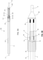
- FIG. 1 a longitudinal cross section of the distal end of one embodiment of the present disclosure is shown with catheter assembly 2, outer catheter 4, inner catheter 6, inner catheter extension 8, outer adapter 10, support sheath 12, balloon 14, inner catheter lumen 16, annular lumen 18, fluid channel 20, proximal balloon bond 22, and distal balloon bond 24.
- a coaxial catheter design is shown with outer catheter 4, having a proximal end and a distal end and a diameter larger than inner catheter 6, also having a proximal end and a distal end, whereby inner catheter 6 is positioned longitudinally inside of outer catheter 4.
- Inner catheter 6 extends distally beyond the distal end of outer catheter 4, as indicated by extension distance 8, said inner catheter extension providing a reduction in diameter whereupon a balloon or accessory can be attached.
- Inner catheter 6 and outer catheter 4 are each typically composed of a laminate or composite of at least two layers, with a steel or other braid, coil, woven, and/or reinforcing material positioned between the layers or forming one of the layers.
- a reinforcing material is molded within a less rigid base material such that the reinforcing layer is embedded in an encapsulation layer.
- This construction is provided to allow kink resistance and strength to withstand high pressure injection. Given the multi-layer construction, these walls typically have a thickness of 0.1 mm to 1 mm which consumes radial area which could otherwise be used to increase the size of the injection lumen or balloon inflation lumen. Therefore, thin wall construction is optimal, provided that strength, kink resistance and a tolerance to high pressure is maintained.
- outer adapter 10 is composed of a single layer flexible material such as Pebax, polyamide, polyethylene, polyurethane or the like and has a wall thickness of 0.0001 mm to 0.01 mm, more typically 0.001 mm to 0.0050 mm, said thickness being less than that of the inner catheter or outer catheter.
- the outer catheter 4 has a wall thickness of about 0.0635 mm and the outer adapter 10 has a wall thickness of about 0.00635 mm.
- the wall thickness of the outer adapter 10 is no more than about 15% of the wall thickness of the outer catheter 4.
- the thickness and material type is different from that of the outer catheter and optimized for maximizing balloon inflation and injection lumen diameters, flexibility and bondability of the balloon material to the adapter.
- the proximal end of outer adapter 10 is circumferentially oriented about the outer surface of the distal end of outer catheter 4 and steps centrally to a reduced diameter at a point distal to the distal end of outer catheter 4, said reduced diameter is circumferentially oriented about inner catheter 6.
- support sheath 12 is positioned over the distal end of outer catheter 4 and the proximal end of outer adapter 10, and the distal end of support sheath 12 is positioned over the proximal end of balloon 14.
- Support sheath 12 compresses the proximal end of balloon 14 into the space below the other diameter of outer catheter 4, assuring that the balloon will return to a position below the outer diameter of outer catheter 4 and strengthens balloon bond 22 on outer adapter 10.
- support sheath 12 is composed of a single layer flexible material with substantially the same wall thickness and material composition as the outer adapter 10.
- the proximal end of inner catheter 6 is in fluid communication with the distal end of inner catheter 6 by way of inner catheter lumen 16.
- a space between outer catheter 4 and inner catheter 6 defines a generally annular lumen 18, and a space between the reduced diameter of outer adapter 10 and inner catheter 6 defines fluid channel 20.
- Balloon 14 is bonded at its proximal end to the reduced diameter of outside adapter 10 by proximal balloon bond 22, and the distal end of balloon 14 is bonded to inside catheter 6 at distal balloon bond 24, such that proximal balloon bond 22 and distal balloon bond 24 are radially inward from the outside diameter of outer catheter 4.
- proximal balloon bond 22 and distal balloon bond 24 are also radially inward from the inside diameter of outer catheter 4, as shown in FIG.
- catheter assembly 2 is in fluid communication with the interior volume of balloon 16 by way of annular lumen 18, and fluid channel 20.
- inner catheter 6 may be located in an offset manner within outer catheter 4 such that the inflation lumen formed therebetween is crescent-shaped rather than annular.
- the aforementioned disclosure enables a balloon microcatheter to be adapted to an optimal: small outer diameter for use in small vessels, flexibility to navigate in tortuous vasculature, high pressure tolerance to allow high flow rates of drug and contrast, short balloon inflation and deflation times, balloon bondability, balloon bond strength and maintenance of the balloon outer diameter to remain below the outer diameter of the outer catheter, even after balloon inflation and deflation.
- FIG. 2 an axial cross section of a coaxial catheter assembly with outer catheter 4, inner catheter 6, inner catheter lumen 16 and annular lumen 18 defining a space between outer catheter 4 and inner catheter 6.
- Inner catheter lumen 16 extends from the proximal end of the outer catheter 4 to the distal end of the outer catheter 4 and allows fluid communication therebetween.
- Annular lumen 18 extends from the proximal end of the catheter assembly to the inner volume of a balloon and allows fluid communication to inflate and deflate the balloon.
- a longitudinal cross section of catheter assembly 30 is shown with outer catheter 4, inner catheter 6, inner catheter lumen 16, annular lumen 18, inner catheter extension 32, external catheter surface 34, internal catheter surface 36 (i.e a portion of the inside diameter of outer catheter 4), inner balloon surface 38 and outer balloon surface 40.
- Outer catheter 4 has a diameter greater than inner catheter 6 and has a length that is less than that of inner catheter 6.
- Annular lumen 18 defines a space between outer catheter 4 and inner catheter 6 and extends from the proximal end of catheter assembly 30 to the inner volume of balloon 14 and allows fluid communication to inflate and deflate the balloon.
- Inner catheter 6 has a length that is greater than that of outer catheter 4 and a lumen 16 that extends from the proximal end of catheter assembly 30 to the distal end of catheter assembly 30 and allows fluid communication therebetween.
- Inner catheter extension 32 with a diameter less than that of outer catheter 4 provides a surface whereby a balloon or other accessory can be attached with the bonding surfaces below the surface of (i.e. radially inward from the outside diameter of) outer catheter 4 and, if desired, the balloon or other accessory can be positioned such that its outer diameter is below the surface of outer catheter 4.
- the balloon bonding surface may also be radially inward from the inside diameter of outer catheter 4.
- External catheter surface 34 defines a circumferential area on the outside of the distal end of outer catheter 4 whereupon adapters and sheaths can be affixed
- internal catheter surface 36 defines a circumferential area on the inside of the distal end of outer catheter 4 whereon adapters can be affixed.
- the diameters of external catheter surface 34 and internal catheter surface 36 are equal to the outer diameter and inner diameter of the catheter selected, respectively, typically from 0.3 mm to 5 mm, and the longitudinal length of the fixation surfaces can be from 0.2 mm to 25 mm, more typically from 1 mm to 10 mm.
- an outer adapter 10 is shown with a diameter reduction between a large diameter surface 42 and a small diameter surface 44.
- outer adapter 10 shows a single step from large diameter surface 42 to small diameter surface 44, the transition can be configured with 2, 3, 4 or more steps or the transition can be a gradual as in a conical adapter.
- the outer adapter 10 provides a connection between the external catheter surface 34, of outer catheter 4 and an inner balloon surface 38 of balloon 14, providing fluid communication between the annular lumen 18 and the inner surface of balloon 14, whereby a proximal balloon bond is positioned between inner balloon surface 38 of balloon 14 and small diameter surface 44 of outer adapter 10, positioning the balloon bond below the surface of the outer diameter of outer catheter 4.
- the outer adapter 10 is made from a plastic polymeric material such as polyester, nylon, Pebax, polyethylene, polyurethane, or other convenient material. In many embodiments, a thin wall is preferred; however any thickness can be used depending on the application. Material thickness will typically range from 0.0003 mm to 1 mm, more typically from 0.003 mm to 0.01 mm.
- the large diameter surface 42 of outer adapter 10 is typically glued, heat bonded, compressed or reflowed into the external catheter surface 34 of outer catheter 4. Reflow has the advantage that large diameter surface 42 of outer adapter 10 melts into the outer surface of outer catheter 4 at external catheter surface 34 and does not increase the diameter of outer catheter 4.
- the diameters of the large diameter surface 42 and the small diameter surface 44 will be dependent on the catheter diameter and the desired positioning of the balloon bonding surface below the outer diameter of outer catheter 4.
- the outer diameter of medical catheters range from about 0.25 mm to 10 mm, more typically from 0.5 mm to 5 mm, thereby making the large diameter surface 42 of the outer adapter 10 range from about 0.5 mm to 4 mm.
- the outside adapter 10 can be any length of convenience, typically 2 mm to 25 mm, more typically 4 mm to 10 mm.
- the outer adapter 10 of the present disclosure is particularly useful in micro-catheters that commonly have small outer diameters in the range of 0.5 mm to 1.5 mm and are used for access into the peripheral vasculature and into small blood vessels.
- an accessory can include a tissue anchor, blade, mechanical occlusion device, partial occlusion device, a device to trap embolic particles, or any device of use in the vasculature.
- inner adapter 46 is shown with a diameter reduction between a large diameter surface 48 and a small diameter surface 50.
- inner adapter 46 is used instead of outer adapter 10.
- inner adapter 46 shows a single step from large diameter surface 48 to small diameter surface 50, the transition can be configured with 2, 3, 4 or more steps or be a gradual transition as in a conical adapter.
- the inner adapter provides a connection between the internal catheter surface 36 of an outer catheter 4 and balloon 14 at inner balloon surface 38, thereby positioning the balloon bonding surface or accessory attachment surface below the outer surface and the inner surface of outer catheter 4.
- the composition, measurements, use and benefits are as stated for FIG. 4A .
- a longitudinal cross section of a support sheath 12 is shown with a proximal end, a distal end, an outer surface 54 and an inner surface 56.
- the support sheath 12 fits circumferentially over the outer catheter 4 at external catheter surface 34 and balloon 14 at outer balloon surface 40.
- Support sheath 12 functions to strengthen the balloon bond and, if desired, hold the proximal end of balloon 14 at or below the outer surface of outer catheter 4.
- the length from proximal to distal ends of the support sheath is typically from 1 mm to 10 mm, more typically from 3 mm to 6 mm and any portion of the length can be bonded to the catheter with the remainder extended over the balloon or other accessory.
- the support sheath has a length that is at least as great as the outside diameter of the distal end of the outer catheter.
- the support sheath 12 is compressed, glued, reflowed or otherwise affixed to the outer catheter and extends over, but may not be attached to a balloon or other accessory.
- the support sheath is made from polymeric material such as silicone, latex, polyester, nylon, Pebax, polyethylene, polyurethane, or other convenient material.
- a thin wall is preferred, however, any thickness can be used depending on the application.
- the support sheath 12 is a heat shrink material that is placed at a desired position over the catheter and balloon, or other accessory, and heated, causing the material to reduce in diameter and compress about the surface of the outer catheter 4 and balloon 14.
- the thickness will typically range from 0.003 mm to 0.05 mm, more typically from 0.006 mm to 0.01 mm.
- Reflow and compression have the advantage that the outer surface 54 of the support sheath 12 melts or is compressed into the outer surface of the outer catheter 4 and does not increase the diameter of the outer catheter.
- the diameter of support sheath 12 is dependent on the catheter diameter. Typically the outer diameter of medical catheters range from about 0.5 mm to 5 mm.
- FIGS. 5A and 5B a longitudinal cross section of a second embodiment of the present disclosure is shown with catheter assembly 58, outer catheter 4, inner catheter 6, outer adapter 10, large diameter surface 42, small diameter surface 44, support sheath 12, nose cone 60, fluid channel 20, balloon 14, proximal balloon bond 22 and distal balloon bond 24.
- External catheter surface 34 of catheter 4 is bonded to the inner surface of the large diameter surface 42 of adapter 10.
- the inner surface of balloon 14 is bonded at its proximal end to the outer surface of small diameter surface 44 of adapter 10, at proximal balloon bond 22 and its distal end is bonded to inner catheter 6 at distal balloon bond 24 that is positioned proximal to nose cone 60.
- Support sheath 12 is positioned such that it extends over external catheter surface 34 of outer catheter 4 and the proximal end of balloon 14.
- the proximal end of support sheath 12 can be bonded, reflowed, compressed or otherwise affixed to external catheter surface 34 of outer catheter 4 and/ or large diameter surface 42 of outer adapter 10, and the distal end of support sheath 12 is positioned over the proximal end of balloon 14 with the advantage of strengthening the balloon bond 22 and, if desired, holding balloon 14 below the surface of outer catheter 4.
- Support sheath 12 can be affixed to external catheter surface 34 and the proximal end of balloon 14, or it may not be affixed to one or both surfaces, provided that it does not move with respect to outer catheter 4 or balloon 14.
- Inner catheter 6 extends beyond the distal end of outer catheter 4 and nose cone 60 is affixed to inner catheter 6 at a location distal to the distal end of outer catheter 4.
- the balloon sits in a pocket between the distal end of outer catheter 4 and the proximal end of nose cone 60 with the advantage of positioning the balloon bond lower than (i.e. radially inward from) the outer diameter of outer catheter 4 and, if desired, the balloon outer diameter, when in its unexpanded configuration, can be positioned so that it is substantially equal to or less than the outer diameter of the outer catheter 4.
- a balloon when in its unexpanded configuration, can be positioned within a pocket at or below the outer surface of outer catheter 4, expand to a diameter greater than outer catheter 4, and then return, upon deflation, to a diameter less than or equal to the outside diameter of outer catheter 4.
- the proximal end of catheter assembly 58 is in fluid communication with the interior space of balloon 14 by way of annular lumen 18 and adapter 10 at fluid channel 20 which is defined by an annular space between the inner surface of small diameter surface 44 of adapter 10 and the outer surface of inner catheter 6.
- Alternate configurations of this embodiment include use of adapter 10 and without the support sheath 12 or use of the support sheath 12 without the adapter 10.
- proximal balloon 14 When only the support sheath 12 is used, the outer diameter of proximal balloon 14 is bonded to the inner surface of the support sheath 12.
- Another configuration of this embodiment includes the use of an outer adapter to affix the balloon to the nose cone 60 or the use of a support sheath to affix balloon 14 to nose cone 60 or the use of both an adapter and support sheath to affix balloon 14 to nose cone 60.
- balloon 14, adapters, support sheaths and none cone 60 have an outer diameter equal to or less than the outer diameter of outer catheter 4.
- FIGS. 6A and 6B a third embodiment of the device of the present disclosure is shown with catheter assembly 62, outer catheter 4, inner catheter 6, outer adapter 10, large diameter surface 42, small diameter surface 44, support sheath 12, fluid channel 20, balloon 14, proximal balloon bond 22, distal balloon bond 24, second outer catheter 64, distal outer adapter 66, large diameter surface 68, small diameter surface 70 and second support sheath 72.
- Inner catheter 6 extends beyond the distal end of outer catheter 4 and second outer catheter 64 may be affixed to inner catheter 6 at a location distal to the distal end of outer catheter 4, whereby balloon 14 is disposed in a pocket between the distal end of outer catheter 4 and the proximal end of second outer catheter 64 with proximal balloon bond 22 and distal balloon bond 24 positioned below the surface of outer catheter 4 and second outer catheter 64.
- balloon 14 is configured with an outer diameter less than or equal to the outer diameter of catheter 4 and second outer catheter 64 and thereby is concealed within a pocket therebetween.
- balloon 14 When inflated to its radially expanded configuration, balloon 14 will have a diameter greater than the outside diameters of outer catheter 4 and second outer catheter 64 and extend radially outward from said pocket. When balloon 14 is then deflated from its radially expanded configuration it will return to a diameter less than or equal to outer catheter 4 and second outer catheter 64 and again be concealed within the pocket.
- the external catheter surface 34 at the distal end of outer catheter 4 is bonded to the inner surface of large diameter surface 42 of adapter 10.
- the proximal end of balloon 14 is bonded at its inner surface to the outer surface of small diameter surface 44 of outer adapter 10 and the distal end of balloon 14 is bonded at its inner surface to the outer diameter of small diameter surface 70 of distal second adapter 66.
- the inner luminal surface of balloon 14 can be bonded at its distal end directly to inner catheter 6.
- the inner diameter of large diameter surface 68 of distal adapter 66 is bonded, reflowed, compressed or otherwise affixed to the proximal end of a second outer catheter 64.
- a flow channel between the inner surface of small diameter surface 70 of second adapter 66 and inner catheter 6 may or may not be present. In the case where one balloon is present the distal end of the balloon will be sealed. However, if a second balloon is positioned distal to a first balloon, then a flow channel may be configured to allow inflation and deflation of a second, third, fourth or any number balloons and it is understood that any number of balloons and outer catheter segments can positioned in series.
- a first support sheath 12 may be positioned such that it extends over the outer surface of the distal end of outer catheter 4 and the proximal end of balloon 14 and a second support sheath 72, may be positioned such that it extends over the outer surface of the proximal end of second outer catheter 64 and the distal end of balloon 14.
- Support sheaths 12 and 72 can be bonded, glued, reflowed, compressed or otherwise affixed to the distal end of outer catheter 4 or proximal end of second outer catheter 64 and may, if desired, be affixed to balloon 14.
- Support sheath 12 provides the advantage of restraining or compressing the proximal end of balloon 14 at the proximal balloon bond 22 and strengthening the balloon bond and preventing detachment.
- a second support sheath 72 adds the advantage of retaining or compressing balloon 14 at distal balloon bond 24 or strengthening the balloon bond and preventing detachment.
- the proximal end of catheter assembly 62 is in fluid communication with the interior space of balloon 14 by way of annular lumen 18 and outside adapter 10 at fluid channel 20, which is defined by an annular space between the inner surface of small diameter surface 44 of adapter 10 and the outer surface of inner catheter 6 as seen by flow path 26.
- Alternate configurations of this embodiment include an outer adapter 10 without a support sheath 12, a support sheath 12 without adapter 10, outer adapter 66 without second support sheath 72, second support sheath 72 without outer adapter 66 or any combination of adapters and support sheaths, provided that the proximal end and distal end of balloon 14 have at least one adapter or sheath or are bonded directly to inner catheter 6 and annular lumen 18 is in fluid communication with the interior surface of balloon 14.
- balloon 14 both support sheaths and both adapters have an outer diameter equal to or less than the outer diameters of outer catheter 4 and second outer catheter 64 of catheter assembly 62, although there is no requirement for balloon 14 to be constrained below the surface of catheter assembly 62, provided that bonding surfaces 22 and/or 24 are positioned below the outer surface of catheter assembly 62. It would be particularly useful when delivering therapy in small vessels, for a balloon or other accessory or tool to be positioned below the surface of a catheter, in its unexpanded state, and then following inflation or deployment be returned to the same positon below the catheter surface.
- FIGS. 7A and 7B a longitudinal cross section of yet another embodiment of the present disclosure is shown with catheter assembly 74, outer catheter 4, inner catheter 6, proximal inner adapter 46, large diameter surface 48, small diameter surface 50, fluid channel 76, distal inner adapter 78, large diameter surface 80, small diameter surface 82 and support sheath 86.
- inner adapters 46 and 78 are used instead of outer adapters whereby the outer surfaces of large diameter surfaces 48 and 80 of inner adapters 46 and 78 are bonded or otherwise affixed to the inner circumference of outer catheter 4 and the inner circumference of second outer catheter 84.
- the balloon 14 is disposed in a pocket between the distal end of outer catheter 4 and the proximal end of second outer catheter 84. It is understood that any combination of adapters and support sheaths can be used.
- the proximal and/or distal balloon bonds are positioned below the outer surfaces of outer catheter 4 and second outer catheter 82 and fluid communication is maintained from the proximal end of catheter assembly 74 and the interior surface of the balloon 14 by way of annular lumen 18 and adapter 46 at fluid channel 76 which is defined by an annular space between the inner surface of small diameter surface 50 of adapter 46 and the outer surface of inner catheter 6.
- a nose cone or other nose piece can be affixed to a location distal to the second outer catheter 84 and that any number of balloons and outer catheter segments can be serially oriented along catheter assembly 74.
- catheter assembly 88 yet another embodiment of the present disclosure is shown with catheter assembly 88, two lumen catheter 90, injection lumen 92, balloon inflation lumen 94, injection lumen extension 96, nose cone 98, outer adapter 100, large diameter surface 102, small diameter surface 104, support sheaths 106 and 108, balloon 110, proximal balloon bond 112, distal balloon bond 114, fluid channel 116 and flow path 118.
- a single catheter with 2 lumens is used instead of the two catheter coaxial construction as described in the above embodiments. While a two lumen catheter is useful for numerous applications, the catheter can also include 3, 4, 5 or more lumens as needed.
- Catheter assembly 88 can be any length useful for medical applications, typically from 25 cm to 250 cm, more typically from 50 cm to 150 cm.
- Injection lumen 92 has a proximal end and a distal end and extends from the proximal end of catheter assembly 88 to the distal end of catheter assembly 88 and provides fluid communication therebetween.
- Balloon inflation lumen 94 has proximal and distal ends and extends from the proximal end of catheter assembly 88 to balloon 110, providing a means for inflation and deflation.
- Injection lumen 92 extends distally beyond the distal end of two lumen catheter 90 and distally beyond the end of balloon lumen 94 as illustrated by injection lumen extension 96 and length 120.
- the injection lumen extension typically has a length in the range of 0.1 cm to 50 cm, more typically from 1 cm to 10 cm.
- Nose cone 98 is positioned about the injection lumen extension 96 at a point that is distal to the distal end of two lumen catheter 90, whereby balloon 110 is disposed in a pocket between the distal end of two lumen catheter 90 and the proximal end of nose cone 98.
- Nose cone 98 is typically placed at a distance of 0.25 cm to 10 cm, more typically from 1 cm to 3 cm from the distal end of two lumen catheter 90 and can be any shape or configuration and can be composed of any convenient material including materials that are radiopaque. For illustration only, the embodiment of FIGS.
- Outer adapter 100 has a large diameter surface 102 and a small diameter surface 104, whereby the inner surface of large diameter surface 102 is bonded to the distal outer surface of two lumen catheter 90 and the small diameter surface is oriented about injection lumen extension 96, such that an annular space between the inner surface of small diameter surface 104 and injection lumen extension 96 is maintained.
- the proximal end the catheter assembly 88 is in fluid communication with the interior space of balloon 110 by way of balloon inflation lumen 94, outer adapter 100, an annular space between the injection lumen extension 96 and the inner surface of the small diameter surface 104 of adapter 100, defined by fluid channel 116 and flow path 118.
- the central injection lumen 92 allow fluid communication therethrough, however, this is not a requirement.
- the injection lumen 92 can be a solid and without fluid communication, thereby configuring a one lumen balloon catheter. It may also be desirable for balloon 110 to sit below the outer diameter of catheter assembly 88, however this is not required. In some embodiments, balloon 110 does not sit below the outer diameter of catheter assembly 88, but at least the proximal balloon bond 112 is positioned below the outer diameter of catheter assembly 88.
- a catheter tip may be provided with a balloon 130 near its distal tip 132, similar or identical to the configurations previously described.
- the balloon 130 may be inflated as shown past a diameter needed to occlude a small blood vessel such that it bulges laterally to one side of the catheter tip 132 as shown.
- This off-center state of balloon 130 forces the distal tip 132 of the catheter to bend laterally in the opposite direction around a "bend point" 134.
- the degree of bend or bend angle of distal tip 132 is a function of the volume of fluid in balloon 130. This arrangement can be used as a means to steer a catheter around a sharp turn.
- FIG. 9B depicts various angles that catheter tip 132 may bend away from the longitudinal axis of the main catheter. As balloon 130 is progressively inflated with more fluid, tip 132 may bend from a straight orientation (a) through various acute angles (b), (c) and (d), to a right angle (e) and to obtuse angles (f) and (g), as shown.
- a protocol for advancing the catheter around a sharp turn comprises the following steps:
- a contrast agent can be injected through the distal tip 132 of the catheter and fluoroscopy can be used to visualize the target vessel.
- Balloon 130 may be configured with a uniform wall thickness, or it may be provided with a thinner wall thickness on one side to ensure that it inflates laterally to the same side every time.
- the wall thickness may be varied to provide a desired shape or inflation profile.
- the balloon is configured to surround the circumference of the catheter, and in other embodiments it can be attached to only one side of the catheter.
- an adhesive may be used between one side of the catheter and part of the inside surface of the balloon to ensure that the balloon does not inflate on that side.
- bend point 134 is the midpoint of a curve.
- the curve may have a radius of 50 mm, 25 mm, 10 mm or less.
- the catheter may be modified at bend point 134 to allow the catheter to bend with less force applied by balloon 130.
- the catheter may have a reduced diameter and/or wall thickness at one or more locations to facilitate easier bending and/or a smaller radius of curvature.
- the bend point can be varied by advancing or retracting a guidewire within the catheter, such that the catheter starts bending just beyond the distal end of the guidewire.
Description
- This application relates generally to medical devices. More specifically, the present disclosure relates to a balloon catheter assembly.
- Catheters are commonly used in medicine for delivery of fluids, therapeutics and implants as well as in sampling tissues and bodily fluids. Catheters can be constructed with balloons or other tools to dilate tissue, block fluid flow or isolate segments of the anatomy. A relatively common use for a catheter is the delivery of drugs to a target tissue using blood vessels as a means of access. When a balloon is used, the vascular compartment distal to the balloon is isolated from the vascular compartment proximal to the balloon and perfusion of diagnostic, therapeutic or embolic agents is localized and concentrated. Transvascular catheters, especially in the peripheral blood circulation, need to have a small axial diameter to allow access into small vessels.
- One common use for a microcatheter is the delivery of embolic agents and anticancer drugs to a tumor.
- According to the NIH, 30,640 people were diagnosed with primary liver cancer (hepatocellular carcinoma, HCC) and 142,820 people were diagnosed with colorectal cancer in the US in 2013. Seventy five percent of these will metastasize to the liver. Liver resection and transplant are the only curative means; however, only small numbers of patients are eligible. Systemic Chemotherapy for primary and metastatic tumors in the liver is ineffective, having a response rate of about 20% and a survival benefit of 10.7 months vs. 7.9 months over symptomatic care.
- Trans-Arterial Embolization therapy is the transvascular injection of drug and/or embolic agents directly into, or in the vicinity of, the tumor vasculature using a microcatheter. Embolization therapy causes a shutdown of blood flow and, when drug or radioactivity is present, simultaneous release of high concentrations of drug or radioactivity. The technique is also noted for its very low level of toxicity. Chemoembolization was established as a standard of care for intermediate stage hepatocellular carcinoma in 2006.
- Numerous studies have demonstrated transarterial embolization to be effective on a number of primary cancers and to have better performance than chemotherapy for both HCC and metastatic colorectal cancers in the liver; however, studies show inconsistent outcomes with reported tumor responses from 15% to 85%. Although anatomical and individual differences are clearly of significance in between-patient variation, clinical studies, each of which include a range of patients, show very different outcomes, indicating that procedural standardization is needed.
- The present state-of-the-art embolization therapy for tumors in the liver relies on high volume "forward flow" from the hepatic artery that is flowing at about 6 ml/sec to deliver embolization agents into the tumor. As embolization progresses, the distal capillaries become occluded and the tumor can no longer accept this high flow rate, even though the tumor is only partially filled with embolic agents. Tumor embolization using high volume flow from the unrestricted hepatic artery causes: (1) rapid embolization of the distal portions of tumor capillaries, (2) rapid onset of high intra-tumor pressure, (3) reflux of blood and embolic agents from the tumor, (4) increased non-target flow into hepatoenteric arteries, and (5) poor filling and distribution of embolic agents in the tumor. This situation results in an uncontrollable number of particles or other embolic agents entering the tumor and high procedural variability.
- Although standardization to an optimal protocol should improve reproducibility and overall outcomes, the procedure is presently without optimization or standardization. The current delivery catheters are unable to control many of the above mentioned variables, making standardization unlikely. There is a need for a delivery system that enables a measurable clinical endpoint, a known quantity of embolic agent delivered, and elimination of non-target embolization. This is a required first step if standardization is to be achieved.
- As a requirement, a delivery catheter that would solve the aforementioned problems, must have a small radial diameter to allow access into small vessels that are typically in the vicinity of the tumor. Presently, balloons are bonded to the external surface of a catheter and necessarily increase its diameter. It would be a significant advantage to construct a balloon catheter whereby a balloon was positioned below the surface of the catheter when in its constrained configuration and return thereto following inflation and deflation. One method to accomplish this is to configure a circumferentially oriented pocket or pockets in a catheter whereby a balloon bonding surface is positioned below the surface of the catheter. The present disclosure is a device that achieves a low profile catheter by positioning the balloon bonding surfaces below the surface of a drug delivery catheter.
-
US patent application No. 10/128,977 describes a coaxial catheter whereby a balloon is bonded to an elongated outer tube to prevent the balloon from telescopingly buckling when the balloon is being pushed across a narrow passage.US patent No. 6,066,157 describes a coaxial coronary angioplasty catheter whereby an anchor joint is configured to allow distal movement of the inner tube and to prevent proximal movement.U.S. Pat. No. 5,647,198 describes a catheter with a pair of spaced apart balloons that define an intra-balloon space. A lumen passes through the catheter and exits within the intra-balloon space allowing injection of drugs, emulsions, fluids and fluid/solid mixtures. A perfusion lumen or bypass extends from a location proximal to the proximal balloon and to the distal tip to allow shunting of blood past the inflated balloons.U.S. Pat. No. 5,674,198 describes a two balloon catheter that is designed for treating a solid tumor. The balloons are positioned to isolate the blood flow into the tumor and allow injection of a vasoocclusive collagen material to block the tumor blood supply. Clifton et al. (1963) Cancer 16:444-452 describes a two balloon catheter for the treatment of lung carcinoma. The four lumen catheter includes a lumen for independent injection in the space between the balloons. Rousselot et al. (1965) JAMA 191:707-710 describes a balloon catheter device for delivering anticancer drugs into the liver. See alsoU.S. Pat. No. 6,780,181 ;U.S. Pat. No. 6,835,189 ;U.S. Pat. No. 7,144,407 ;U.S. Pat. No. 7,412,285 ;U.S. Pat. No. 7,481,800 ;U.S. Pat. No. 7,645,259 ;U.S. Pat. No. 7,742,811 ;U.S. App. No. 2001/008451 ;U.S. App. No. 2001/0041862 ;U.S. App. No. 2003/008726 ;U.S. App. No. 2003/0114878 ;U.S. App. No. 2005/0267407 ;U.S. App. No. 2007/0137651 ;U.S. App. No. 2008/0208118 ;U.S. App. No. 2009/0182227 andU.S. App. No. 2010/0114021 . - Another exemplary catheter balloon assemblies are disclosed in
US 5 047 045 and in Us2012/203173 . - What is needed and is not provided in the prior art is a means of positioning of balloon bonding surfaces and attachment of a balloon below the surface of a catheter body and allow a low profile catheter that is useful in providing therapy within small blood vessels.
- The invention is set out in the appended set of claims. According to aspects of the present disclosure, devices are provided for attachment of a balloon or other vascular occlusion device or tool to a catheter whereby the device bonding surfaces are positioned below the surface of the outer diameter of a catheter body. Such catheters are intended for many medical purposes, but the embodiments described herein are focused on microcatheters intended to perform medical procedures in small blood vessels within the body. Such a catheter can access the vascular system percutaneously from any convenient artery or vein including, but not limited to, the femoral artery, carotid artery or jugular vein.
- In the embodiments of the present disclosure a device comprises an outer catheter, an inner coaxial catheter, an outer adapter, a balloon and optionally a support sheath. The outer catheter having a proximal end and a distal end, the distal end having a wall thickness, the outer catheter comprising at least two layers including a reinforcing layer and a base layer; the inner catheter located coaxially within a lumen of the outer catheter, the inner catheter having an injection lumen extending therethrough, the inner and outer catheters forming an inflation lumen therebetween wherein the inner catheter has a distal end that extends distally beyond the distal end of the outer catheter; the outer adapter having a proximal end and a distal end, the proximal end being sized to fit over an outside diameter of the distal end of the outer catheter and configured to be affixed thereto, the distal end of the outer adapter having a reduced outer diameter that is smaller than an outside diameter of the distal end of the outer catheter, the distal end of the outer adapter having an inside diameter that is larger than an outside diameter of the inner catheter, thereby forming a fluid channel therebetween that is in fluid communication with the inflation lumen, the outer adapter having an outer adapter wall thickness that is thinner than the wall thickness of the distal end of the outer catheter; and the balloon having a proximal end with an inner surface affixed to the reduced outer diameter of the outer adapter, the balloon having a distal end with an inner surface affixed to the outside diameter of the inner catheter, the balloon having an interior space that is in fluid communication with the fluid channel, wherein the balloon resides entirely within a predetermined volume having an outer diameter equal to or less than the outside diameter of the distal end of the outer catheter when the balloon is in a deflated configuration, wherein the balloon can be inflated by introducing a fluid through the inflation lumen and fluid channel into the interior space of the balloon, and wherein the balloon can then be deflated by removing the fluid from the interior space such that the balloon returns entirely within the predetermined volume. In this instance, the proximal end of the adapter is larger in diameter than the distal aspect and is attached to outer distal end of the outer catheter, typically in a manner that positions the proximal adapter below the surface of the distal outer catheter. The distal aspect of the adapter has a smaller diameter than the proximal aspect, whereby the outer surface of the distal aspect of the adapter is positioned below the surface of the outer catheter and a balloon can be bonded to the outer surface of the distal aspect of the adapter, thereby positioning the balloon bonding surface below the outer catheter surface. The proximal portion of a support sheath can be attached circumferentially to the outer surface of the distal outer catheter, typically in a manner that positions the sheath below the surface of the distal outer catheter and the distal portion of the sheath is positioned over the proximal end of the balloon. One advantage of the sheath of the present disclosure is to hold the proximal balloon to the distal adapter and thereby strengthening the balloon attachment. Advantages of the device of the present disclosure include a balloon with at least one bond below the outer surface of an outer catheter, providing a low profile, a strong bonding of the balloon to the catheter assembly and rapid inflation and deflation of a balloon, even with viscous solutions such as radiopaque contrast media.
- In some examples of the present disclosure, the device comprises an outer catheter, an inner coaxial catheter, a sheath, an inner adapter and a balloon. The outer catheter has a proximal end, a distal end and a lumen that extends therethrough. The inner catheter is a smaller diameter than the outer catheter and has a proximal end, a distal end and a lumen extending therethrough. An inflatable balloon has an inner surface that at least partially defines an interior volume. The balloon also has a proximal surface and a distal surface and a channel that extends longitudinally through the balloon, said channel is configured to provide fluid communication between the proximal surface of the balloon and the distal surface of the balloon. The inner catheter is positioned inside the outer catheter, thereby forming an annular space between the inner and outer catheter, said annular space is in fluid communication with the inner volume of the balloon and provides a lumen for balloon inflation and deflation. The inner catheter extends distally for some distance beyond the distal end of the outer catheter, providing a reduced diameter whereby a balloon or other accessory can be circumferentially disposed at a level that is below the outer catheter. At its distal end, the balloon can be bonded to the extension of the inner catheter. The balloon is attachable to the distal end of the outer catheter using the an inner adapter and sheath of the present disclosure which allow the distal balloon bond to be positioned below the surface of the outer diameter of the outer catheter and, if needed, close abutment of the proximal end of the balloon to the distal end of the outer catheter. In this instance, the proximal end of the adapter is attached to the inner lumenal surface of the distal end of the outer catheter. The proximal portion of the support sheath is attached to the outer surface of the distal outer catheter, typically in a manner that positions the sheath below the surface of the distal outer catheter and the distal portion of the sheath is positioned over the proximal end of the balloon, whereby it may or may not be affixed. Advantages of the adapter are to provide a bonding surface for a balloon that is below the surface of a catheter assembly and provide an annular inflation channel which allows the balloon to inflate and deflate rapidly, even with viscous fluids such as contrast media. An advantage of the support sheath of the present disclosure is to hold the proximal balloon to the adapter and thereby strengthening the balloon attachment.
- In some examples of the present disclosure, a device comprises a two lumen catheter, a support sheath, an outer adapter and a balloon. The inflatable balloon has an inner surface that at least partially defines an interior volume. The balloon also has a proximal surface and a distal surface and a channel that extends longitudinally through the balloon, said channel is configured to provide fluid communication between the proximal surface of the balloon and the distal surface of the balloon. The two lumen catheter has a proximal end, a distal end and two lumens, a first injection lumen that is in fluid communication with the distal end of the catheter and provides a channel to deliver therapeutic agents to a target tissue or aspirate fluids for analysis and a second lumen that is in fluid communication with the interior surface of the balloon and provides for inflation and deflation. The first injection lumen typically extends for some distance distally beyond the end of the inflation lumen and provides a reduced diameter for circumferential attachment of a balloon or other accessory. The balloon is attachable to the distal end of the catheter using the adapter and sheath of the present disclosure in a manner that positions the balloon bonding surfaces and, if desired, the balloon outer diameter, below the surface of the outer diameter of the outer catheter and, if needed, close abutment of the proximal end of the balloon to the distal end of the catheter. Although it is typically desirable that the balloon outer diameter be positioned below the outer diameter of the catheter, in some instances it may be desirable for the balloon to extend circumferentially outward beyond the outer diameter of the catheter. In this instance, the proximal end of the adapter is larger in diameter than the distal aspect, whereby the inner surface of the balloon is bonded to the outer surface of the distal aspect of the adapter and the inner surface of the proximal aspect of the adapter is attached to distal end of the outer catheter, typically in a manner that positions the proximal adapter substantially below the surface of the distal outer catheter. The proximal portion of a support sheath is attached to the outer surface of the distal outer catheter, typically in a manner that positions the support sheath substantially below the surface of the distal outer catheter and the distal portion of the sheath is positioned over the proximal end of the balloon and may, if desired, be bonded thereto. The distal end of the balloon can then be affixed to the extension of the first lumen whereby the bonding surfaces of the balloon are positioned below the surface of the largest diameter of the catheter assembly. One advantage of the sheath of the present disclosure is to hold the proximal balloon to the distal adapter and thereby strengthening the balloon attachment and compressing the bond joint to minimize size. Advantages of the adapter of the present disclosure are to position the balloon bonding areas below the surface of a catheter assembly and to provide a substantially circumferential balloon inflation area that can allow rapid and substantially symmetrical inflation and deflation, even with viscous solutions such as radiopaque contrast media.
- In some embodiments of the present disclosure a nose piece, nose cone, marker band or other similar structure is positioned circumferentially about an extension of the inner catheter or injection lumen and distal to the distal end of the balloon inflation lumen, whereby the proximal end the balloon is bonded according to the present disclosure below the surface of the catheter and the distal end of the balloon can be bonded directly to the distal extension or to the nose piece using the device of the present disclosure, provided that all balloon bonding surfaces are below the outer diameter of the catheter assembly. In this instance, a pocket is formed between the distal catheter and the proximal end of the nose piece.
- In some examples of the present disclosure a device comprises a first outer catheter, a second outer catheter, an inner coaxial catheter, at least one outer or inner adapter, at least one support sheath and a balloon. The inner catheter is positioned inside the outer catheter, thereby forming an annular space between the inner and outer catheter, said annular space is in fluid communication with the inner volume of the balloon and provides a lumen for balloon inflation and deflation. The inner catheter extends distally for some distance beyond the distal end of the first outer catheter, providing a reduced diameter, whereby a balloon or other accessory can be circumferentially disposed at a level that is below the outer catheter. The second outer catheter is configured such that it can be circumferentially oriented about the distal extension of the inner catheter at some distance from the distal end of the first outer catheter to form a pocket between the distal end of the first outer catheter and the second outer catheter. For the purpose of this embodiment, the first outer catheter and the second outer catheter are of the same diameter, however, the first outer catheter and the second outer catheter need not have the same diameter. A balloon is oriented circumferentially about the inner catheter at a position that is distal to the first outer catheter and proximal to the second outer catheter and within a pocket formed therebetween. The proximal end the balloon is bonded according to the present disclosure below the surface of the first outer catheter and the distal end of the balloon can be bonded directly to the distal extension or to the second outer catheter using the device of the present disclosure, provided that all balloon bonding surfaces are below the outer diameter of the catheter assembly.
- In some examples of the present disclosure an adapter is positioned at the proximal end of the balloon, the distal end of the balloon, or both proximal and distal ends of the balloon or an adapter is not present at either the proximal or distal ends of the balloon with the requirement that there is at least one adapter or one sheath at each balloon bonding location. In this instance, when an adapter in not present, the outer surface of the balloon is bonded to the inner surface of the sheath.
- In some examples a sheath is positioned at the proximal end of the balloon, the distal end of the balloon, or both proximal and distal ends of the balloon or a sheath is not present at either the proximal or distal end of the balloon with the requirement that there is at least one adapter or sheath at each bonding location. In this instance, when an adapter in not present, the outer surface of the balloon is bonded to the inner surface of the sheath.
- In some examples the sheath is positioned on the distal and/or proximal balloon and does not extend over the outer catheter and/or nose piece.
- In some examples the sheath is replaced by a thread, clamp, band or other circumferential restraining device that is tightly wrapped about the balloon segment that is over the adapter.
- In some examples, a balloon catheter assembly is provided with an outer catheter, an inner catheter, an outer adapter, a balloon and a support sheath. The outer catheter has a proximal end and a distal end, and the distal end has a wall thickness. The outer catheter comprises at least two layers including a reinforcing layer and a base layer which may be less rigid. The inner catheter is located coaxially within a lumen of the outer catheter, and the inner catheter has an injection lumen extending therethrough. The inner and outer catheters form an inflation lumen therebetween. The outer adapter has a proximal end and a distal end. The proximal end is sized to fit over an outside diameter of the distal end of the outer catheter and configured to be affixed thereto. The distal end of the outer adapter has a reduced outer diameter that is smaller than an outside diameter of the distal end of the outer catheter. The distal end of the outer adapter has an inside diameter that is larger than an outside diameter of the inner catheter, thereby forming a fluid channel therebetween that is in fluid communication with the inflation lumen. The outer adapter has a single layer and is formed of a material that is different from that of the outer catheter base layer. The outer adapter has a wall thickness that is no more than 15% of the wall thickness of the distal end of the outer catheter. The balloon has a proximal end with an inner surface affixed to the reduced outer diameter of the outer adapter, and the balloon has a distal end with an inner surface affixed to the outside diameter of the inner catheter. The balloon has an interior space that is in fluid communication with the fluid channel. The support sheath has a proximal end positioned over an outside diameter of the outer adapter and a distal end positioned over an outside diameter of the proximal end of the balloon. The support sheath is composed of a single layer, being formed of a material substantially the same as the material of the outer adapter, and having a wall thickness substantially the same as the wall thickness of the outer adapter. The balloon resides entirely within a predetermined volume having an outer diameter substantially equal to or less than the outside diameter of the distal end of the outer catheter when the balloon is in a deflated configuration. The balloon can be inflated by introducing a fluid through the inflation lumen and fluid channel into the interior space of the balloon. The balloon can then be deflated by removing the fluid from the interior space such that the balloon returns entirely within the predetermined volume.
- In all of the above embodiments, the inner catheter has a distal end that extends distally beyond the distal end of the balloon. The balloon catheter assembly may further comprise a nosecone located on the distal end of inner catheter distal to the balloon, the nosecone having an outer diameter substantially equal to the outside diameter of the distal end of the outer catheter such that the balloon is recessed in a pocket formed between the nosecone and the outer catheter when the balloon is in the deflated configuration. The balloon catheter assembly may further comprise a proximal bond that affixes the inner surface of the proximal end of the balloon to the reduced outer diameter of the outer adapter, and a distal bond that affixes the inner surface of the distal end of the balloon to the outside diameter of the inner catheter. In some examples, both the proximal bond and the distal bond are located radially inward from the outside diameter of the distal end of the outer catheter. In some examples, both the proximal bond and the distal bond are located radially inward from an inside diameter of the distal end of the outer catheter. The inflation lumen may have a substantially annular cross-section. The outer catheter may comprise a base material and a different reinforcing material, and the outer adapter may be made of a plastic polymeric material. The reduced outer diameter portion of the outer adapter may have a wall thickness less than 0.01 mm. In some embodiments, the support sheath has a length that is at least as great as the outside diameter of the distal end of the outer catheter.
- In some examples which fall outside of the scope of the present invention and are present for illustration purposes only, methods of using a balloon catheter assembly are provided. The method may include providing a balloon catheter assembly having an outer catheter, an inner catheter, an outer adapter, a balloon and a support sheath. The outer catheter has a proximal end and a distal end, and the distal end has a wall thickness. The outer catheter has at least two layers including a reinforcing layer and a base layer which may be less rigid. The inner catheter is located coaxially within a lumen of the outer catheter, and the inner catheter has an injection lumen extending therethrough. The inner and outer catheters form an inflation lumen therebetween. The outer adapter has a proximal end and a distal end, the proximal end being sized to fit over an outside diameter of the distal end of the outer catheter and configured to be affixed thereto. The distal end of the outer adapter has a reduced outer diameter that is smaller than an outside diameter of the distal end of the outer catheter. The distal end of the outer adapter has an inside diameter that is larger than an outside diameter of the inner catheter, thereby forming a fluid channel therebetween that is in fluid communication with the inflation lumen. The outer adapter has a single layer and is formed of a material that is different from that of the outer catheter base layer. The outer adapter has a wall thickness that is no more than 15% of the wall thickness of the distal end of the outer catheter. The balloon has a proximal end with an inner surface affixed to the reduced outer diameter of the outer adapter, and has a distal end with an inner surface affixed to the outside diameter of the inner catheter. The balloon has an interior space that is in fluid communication with the fluid channel. The support sheath has a proximal end positioned over an outside diameter of the outer adapter and a distal end positioned over an outside diameter of the proximal end of the balloon. The support sheath is composed of a single layer, being formed of a material substantially the same as the material of the outer adapter, and has a wall thickness substantially the same as the wall thickness of the outer adapter.
- The above methods which fall outside of the scope of the present invention and are present for illustration purposes only, may further include inserting a distal end of the balloon catheter assembly into a blood vessel of a body, and inflating the balloon by introducing a fluid through the inflation lumen and fluid channel into the interior space of the balloon to at least partially occlude blood flow in the blood vessel. The methods may also include injecting a substance into the blood vessel through the injection lumen, deflating the balloon by removing the fluid from the interior space of the balloon such that the balloon returns entirely within a predetermined volume having an outer diameter substantially equal to or less than the outside diameter of the distal end of the outer catheter, and withdrawing the distal end of the balloon catheter assembly from the blood vessel.
- In some of the above methods, which fall outside of the scope of the present invention and are present for illustration purposes only, the inner catheter may have a distal end that extends distally beyond the distal end of the balloon. The balloon catheter assembly may further comprise a nosecone located on the distal end of inner catheter distal to the balloon, the nosecone having an outer diameter substantially equal to the outside diameter of the distal end of the outer catheter such that the balloon is recessed in a pocket formed between the nosecone and the outer catheter when the balloon is in the deflated configuration. The balloon catheter assembly may further comprise a proximal bond that affixes the inner surface of the proximal end of the balloon to the reduced outer diameter of the outer adapter, and a distal bond that affixes the inner surface of the distal end of the balloon to the outside diameter of the inner catheter. In some embodiments, the proximal bond and the distal bond are located radially inward from the outside diameter of the distal end of the outer catheter. In some embodiments, both the proximal bond and the distal bond are located radially inward from an inside diameter of the distal end of the outer catheter. The inflation lumen may have a substantially annular cross-section. The outer catheter may comprise a base material and a different reinforcing material, and the outer adapter may be made of a plastic polymeric material. In some embodiments, the reduced outer diameter portion of the outer adapter has a wall thickness less than 0.01 mm. The support sheath may have a length that is at least as great as the outside diameter of the distal end of the outer catheter.
- In some examples which fall outside of the scope of the present invention and are present for illustration purposes only, methods of steering a balloon catheter assembly are provided. The methods may include providing a balloon catheter assembly, the assembly comprising a catheter body having a proximal end and a distal tip portion, and a balloon affixed near the distal tip portion. The balloon may have an interior space that is in fluid communication with an inflation lumen extending from the balloon towards the proximal end of the catheter body. The methods may also include inserting the distal tip portion of the balloon catheter assembly into a blood vessel of a body, and inflating the balloon by introducing a fluid through the inflation lumen into the interior space of the balloon sufficient to laterally deflect the distal tip portion from a longitudinal axis of the catheter body. The catheter assembly is then advanced through the blood vessel in the direction of the deflected distal tip portion.
- In some of the above methods, which fall outside of the scope of the present invention and are present for illustration purposes only, the advancing step comprises advancing the distal tip portion from the blood vessel into a branch vessel. The methods may also comprise extending a guidewire from the distal tip portion before the advancing step, and then advancing the distal tip over the extended guidewire. The methods may comprise locating a distal end of a guidewire within the catheter body at a point adjacent to the balloon before deflecting the distal tip portion. The methods may comprise rotating the catheter body axially after deflecting the distal tip portion such that the tip portion is pointed in a desired direction.
- While aspects of the present disclosure will be described with particular reference to attachment of a balloon to a distal location on a catheter, the same principle can be applied to the attachment of any device that is positioned below the surface of a catheter.
- Novel features of the disclosure are set forth with particularity in the claims that follow. A better understanding of the features and advantages of the present disclosure will be obtained by reference to the following detailed description that sets forth illustrative embodiments, in which principles of the disclosure are utilized, and the accompanying drawings (which are not necessarily shown to scale) of which:
-
FIG. 1 is a longitudinal cross section of one embodiment of the present disclosure with balloon bonds below the surface of the outer catheter; -
FIG. 2 is an axial cross section of a coaxial catheter; -
FIG. 3 is a longitudinal view of a coaxial catheter assembly; -
FIG. 4A is a side view of an outer adapter component; -
FIG. 4B is a side view of an inner adapter component; -
FIG. 4C is a side view of a support sheath component; -
FIG 5A is a longitudinal cross section of one embodiment of the present disclosure including a nose cone; -
FIG. 5B is an enlarged view of the distal end of the catheter shown inFIG 5A ; -
FIG. 6A is a longitudinal cross section of an embodiment of the present disclosure including a second outer catheter; -
FIG. 6B is an enlarged view of the distal end of the catheter shown inFIG. 6A ; -
FIG. 7A is a longitudinal cross section of an embodiment of the present disclosure including an inner adapter; -
FIG. 7B is an enlarged view of the distal end of the catheter shown inFIG. 7A ; -
FIG. 8A is a longitudinal cross section of a fourth embodiment of the present disclosure including a two lumen catheter; -
FIG. 8B is an enlarged view of the distal end of the catheter shown inFIG. 8A ; -
FIG. 9A is a side view of a catheter balloon inflated to the extent that it laterally deflects the distal tip of the catheter for steering; -
FIG. 9B is the same asFIG. 9A with markings added to show various deflection angles. - A standard microcatheter for drug delivery is designed to access small vasculature and necessarily has a small outer diameter in the range of 0.5 mm to 2 mm more optimally 0.75 mm to 1 mm. For use in the peripheral vasculature, and in particular for tumor embolization, delivery catheters are typically 75 cm to 175 cm in length. Once the catheter is oriented at a target site within the blood vessel, drug, embolic agents, contrast or other fluids are injected through a lumen that extends longitudinally from proximal to distal ends. It is common that the fluids are viscous and must be injected at high flow rates in the range of 1 ml/second to 10 ml/second. However, flow rate is limited by injection lumen diameter or cross sectional area, length and the ability of the catheter wall to withstand high pressures in the range of 250 psi to 2000 psi, more typically in the range of 500 psi to 1,500 psi. Given that the catheter length is fixed by the requirements of the transvascular procedure, flow rate can be maximized by making the injection lumen and injection pressure tolerance as high as possible.
- When considering a balloon microcatheter, an additional lumen that extends longitudinally from proximal to distal ends of the catheter is added for balloon inflation and deflation. In many embodiments, it is optimal for the balloon to inflate and deflate in as short a time as possible and in the range or 10 seconds to a maximum of 60 seconds. When balloons occlude or dilate blood vessels, it can be necessary for deflation to occur rapidly to avoid complications. Often the balloon is inflated with radiopaque contrast which is a viscous fluid. Therefore, it is desirable that the balloon inflation lumen also be as large as possible.
- Since microcatheters have small cross sections, it is a challenge to achieve both rapid drug injection speed, which favors large injection lumen size, and rapid balloon inflation and deflation times, which favor large balloon lumens.
- Further, it would be highly desirable for the mounted balloon not to increase the outer diameter of the catheter since it needs to maintain a small profile and it is optimal to mount the balloon so that in its retracted configuration it does not extend beyond the outer diameter of the catheter.
- Transvascular microcatheters should also be flexible, most importantly at the location of the balloon which is mounted at the distal portion of the catheter to allow them to advance through tortuous vasculature. Balloon bonding adhesives tend to be rigid and measures should be taken to construct the balloon bonding surfaces to be flexible.
- Therefore, in many embodiments, optimal characteristics of a balloon micocatheter include: 1) a large drug injection lumen, 2) a large balloon inflation lumen, 3) a catheter that withstands high pressure, and 4) a flexible distal catheter portion.
- Strong bonding of the balloon to the catheter is also important to prevent detachment during a medical procedure and to assure that post inflation, the balloon can return to a position below the surface of the outer diameter of the catheter.
- The devices disclosed herein solve the aforementioned challenges and enable a balloon microcatheter to be adapted to include a large injection lumen, a large balloon inflation lumen, a flexible distal catheter portion and strong balloon bonding that assure the balloon will return to a retracted diameter less than that of the catheter's outer diameter.
- The device of the present disclosure provides a means to affix a balloon to a catheter such that the balloon bonds are positioned below the surface (i.e. radially inward of the outside diameter) of the catheter assembly and, if desired, the balloon in its uninflated configuration can be positioned below the outer surface of the catheter assembly. The present device allows a balloon to be inflated from below the surface of a catheter assembly and when deflated, return thereto. Such a balloon catheter assembly, as disclosed herein, has a small profile, a strong attachment of the balloon to the catheter and rapid inflation and deflation times even with viscous solutions.
- Referring to
FIG. 1 , a longitudinal cross section of the distal end of one embodiment of the present disclosure is shown withcatheter assembly 2,outer catheter 4,inner catheter 6,inner catheter extension 8,outer adapter 10,support sheath 12,balloon 14,inner catheter lumen 16,annular lumen 18,fluid channel 20,proximal balloon bond 22, anddistal balloon bond 24. In this embodiment, a coaxial catheter design is shown withouter catheter 4, having a proximal end and a distal end and a diameter larger thaninner catheter 6, also having a proximal end and a distal end, wherebyinner catheter 6 is positioned longitudinally inside ofouter catheter 4.Inner catheter 6 extends distally beyond the distal end ofouter catheter 4, as indicated byextension distance 8, said inner catheter extension providing a reduction in diameter whereupon a balloon or accessory can be attached. -
Inner catheter 6 andouter catheter 4 are each typically composed of a laminate or composite of at least two layers, with a steel or other braid, coil, woven, and/or reinforcing material positioned between the layers or forming one of the layers. In some embodiments, a reinforcing material is molded within a less rigid base material such that the reinforcing layer is embedded in an encapsulation layer. This construction is provided to allow kink resistance and strength to withstand high pressure injection. Given the multi-layer construction, these walls typically have a thickness of 0.1 mm to 1 mm which consumes radial area which could otherwise be used to increase the size of the injection lumen or balloon inflation lumen. Therefore, thin wall construction is optimal, provided that strength, kink resistance and a tolerance to high pressure is maintained. In this exemplary embodiment,outer adapter 10 is composed of a single layer flexible material such as Pebax, polyamide, polyethylene, polyurethane or the like and has a wall thickness of 0.0001 mm to 0.01 mm, more typically 0.001 mm to 0.0050 mm, said thickness being less than that of the inner catheter or outer catheter. In some embodiments, theouter catheter 4 has a wall thickness of about 0.0635 mm and theouter adapter 10 has a wall thickness of about 0.00635 mm. In some embodiments, the wall thickness of theouter adapter 10 is no more than about 15% of the wall thickness of theouter catheter 4. The thickness and material type is different from that of the outer catheter and optimized for maximizing balloon inflation and injection lumen diameters, flexibility and bondability of the balloon material to the adapter. - The proximal end of
outer adapter 10 is circumferentially oriented about the outer surface of the distal end ofouter catheter 4 and steps centrally to a reduced diameter at a point distal to the distal end ofouter catheter 4, said reduced diameter is circumferentially oriented aboutinner catheter 6. At its proximal end,support sheath 12 is positioned over the distal end ofouter catheter 4 and the proximal end ofouter adapter 10, and the distal end ofsupport sheath 12 is positioned over the proximal end ofballoon 14.Support sheath 12 compresses the proximal end ofballoon 14 into the space below the other diameter ofouter catheter 4, assuring that the balloon will return to a position below the outer diameter ofouter catheter 4 and strengthensballoon bond 22 onouter adapter 10. In this exemplary embodiment,support sheath 12 is composed of a single layer flexible material with substantially the same wall thickness and material composition as theouter adapter 10. - The proximal end of
inner catheter 6 is in fluid communication with the distal end ofinner catheter 6 by way ofinner catheter lumen 16. A space betweenouter catheter 4 andinner catheter 6 defines a generallyannular lumen 18, and a space between the reduced diameter ofouter adapter 10 andinner catheter 6 definesfluid channel 20.Balloon 14 is bonded at its proximal end to the reduced diameter ofoutside adapter 10 byproximal balloon bond 22, and the distal end ofballoon 14 is bonded toinside catheter 6 atdistal balloon bond 24, such thatproximal balloon bond 22 anddistal balloon bond 24 are radially inward from the outside diameter ofouter catheter 4. In this exemplary embodiment,proximal balloon bond 22 anddistal balloon bond 24 are also radially inward from the inside diameter ofouter catheter 4, as shown inFIG. 1 . The proximal end ofcatheter assembly 2 is in fluid communication with the interior volume ofballoon 16 by way ofannular lumen 18, andfluid channel 20. In some embodiments,inner catheter 6 may be located in an offset manner withinouter catheter 4 such that the inflation lumen formed therebetween is crescent-shaped rather than annular. - The aforementioned disclosure enables a balloon microcatheter to be adapted to an optimal: small outer diameter for use in small vessels, flexibility to navigate in tortuous vasculature, high pressure tolerance to allow high flow rates of drug and contrast, short balloon inflation and deflation times, balloon bondability, balloon bond strength and maintenance of the balloon outer diameter to remain below the outer diameter of the outer catheter, even after balloon inflation and deflation.
- Referring to
FIG. 2 an axial cross section of a coaxial catheter assembly withouter catheter 4,inner catheter 6,inner catheter lumen 16 andannular lumen 18 defining a space betweenouter catheter 4 andinner catheter 6.Inner catheter lumen 16 extends from the proximal end of theouter catheter 4 to the distal end of theouter catheter 4 and allows fluid communication therebetween.Annular lumen 18 extends from the proximal end of the catheter assembly to the inner volume of a balloon and allows fluid communication to inflate and deflate the balloon. - Referring to
FIG. 3 , a longitudinal cross section ofcatheter assembly 30 is shown withouter catheter 4,inner catheter 6,inner catheter lumen 16,annular lumen 18,inner catheter extension 32,external catheter surface 34, internal catheter surface 36 (i.e a portion of the inside diameter of outer catheter 4),inner balloon surface 38 andouter balloon surface 40.Outer catheter 4 has a diameter greater thaninner catheter 6 and has a length that is less than that ofinner catheter 6.Annular lumen 18 defines a space betweenouter catheter 4 andinner catheter 6 and extends from the proximal end ofcatheter assembly 30 to the inner volume ofballoon 14 and allows fluid communication to inflate and deflate the balloon.Inner catheter 6 has a length that is greater than that ofouter catheter 4 and alumen 16 that extends from the proximal end ofcatheter assembly 30 to the distal end ofcatheter assembly 30 and allows fluid communication therebetween.Inner catheter extension 32 with a diameter less than that ofouter catheter 4, provides a surface whereby a balloon or other accessory can be attached with the bonding surfaces below the surface of (i.e. radially inward from the outside diameter of)outer catheter 4 and, if desired, the balloon or other accessory can be positioned such that its outer diameter is below the surface ofouter catheter 4. In some embodiments, the balloon bonding surface may also be radially inward from the inside diameter ofouter catheter 4.External catheter surface 34 defines a circumferential area on the outside of the distal end ofouter catheter 4 whereupon adapters and sheaths can be affixed, andinternal catheter surface 36 defines a circumferential area on the inside of the distal end ofouter catheter 4 whereon adapters can be affixed. The diameters ofexternal catheter surface 34 andinternal catheter surface 36 are equal to the outer diameter and inner diameter of the catheter selected, respectively, typically from 0.3 mm to 5 mm, and the longitudinal length of the fixation surfaces can be from 0.2 mm to 25 mm, more typically from 1 mm to 10 mm. - Referring to
FIG. 4A , a longitudinal cross section of anouter adapter 10 is shown with a diameter reduction between alarge diameter surface 42 and asmall diameter surface 44. Althoughouter adapter 10 shows a single step fromlarge diameter surface 42 tosmall diameter surface 44, the transition can be configured with 2, 3, 4 or more steps or the transition can be a gradual as in a conical adapter. Theouter adapter 10 provides a connection between theexternal catheter surface 34, ofouter catheter 4 and aninner balloon surface 38 ofballoon 14, providing fluid communication between theannular lumen 18 and the inner surface ofballoon 14, whereby a proximal balloon bond is positioned betweeninner balloon surface 38 ofballoon 14 andsmall diameter surface 44 ofouter adapter 10, positioning the balloon bond below the surface of the outer diameter ofouter catheter 4. In some embodiments, theouter adapter 10 is made from a plastic polymeric material such as polyester, nylon, Pebax, polyethylene, polyurethane, or other convenient material. In many embodiments, a thin wall is preferred; however any thickness can be used depending on the application. Material thickness will typically range from 0.0003 mm to 1 mm, more typically from 0.003 mm to 0.01 mm. Thelarge diameter surface 42 ofouter adapter 10 is typically glued, heat bonded, compressed or reflowed into theexternal catheter surface 34 ofouter catheter 4. Reflow has the advantage thatlarge diameter surface 42 ofouter adapter 10 melts into the outer surface ofouter catheter 4 atexternal catheter surface 34 and does not increase the diameter ofouter catheter 4. The diameters of thelarge diameter surface 42 and thesmall diameter surface 44 will be dependent on the catheter diameter and the desired positioning of the balloon bonding surface below the outer diameter ofouter catheter 4. Typically the outer diameter of medical catheters range from about 0.25 mm to 10 mm, more typically from 0.5 mm to 5 mm, thereby making thelarge diameter surface 42 of theouter adapter 10 range from about 0.5 mm to 4 mm. Theoutside adapter 10 can be any length of convenience, typically 2 mm to 25 mm, more typically 4 mm to 10 mm. Theouter adapter 10 of the present disclosure is particularly useful in micro-catheters that commonly have small outer diameters in the range of 0.5 mm to 1.5 mm and are used for access into the peripheral vasculature and into small blood vessels. In this instance, it is important to keep the outer diameter of the catheter as small as possible. If a balloon or other accessory is placed on the catheter, it can be a significant advantage to bond or otherwise mount the accessory below at least the outer surface ofouter catheter 4. In addition to a balloon, an accessory can include a tissue anchor, blade, mechanical occlusion device, partial occlusion device, a device to trap embolic particles, or any device of use in the vasculature. - Referring to
FIG. 4B , a longitudinal cross section of aninner adapter 46 is shown with a diameter reduction between alarge diameter surface 48 and asmall diameter surface 50. In some embodiments,inner adapter 46 is used instead ofouter adapter 10. Althoughinner adapter 46 shows a single step fromlarge diameter surface 48 tosmall diameter surface 50, the transition can be configured with 2, 3, 4 or more steps or be a gradual transition as in a conical adapter. The inner adapter provides a connection between theinternal catheter surface 36 of anouter catheter 4 andballoon 14 atinner balloon surface 38, thereby positioning the balloon bonding surface or accessory attachment surface below the outer surface and the inner surface ofouter catheter 4. The composition, measurements, use and benefits are as stated forFIG. 4A . - Referring now to
FIG. 4C , a longitudinal cross section of asupport sheath 12 is shown with a proximal end, a distal end, an outer surface 54 and aninner surface 56. Thesupport sheath 12 fits circumferentially over theouter catheter 4 atexternal catheter surface 34 andballoon 14 atouter balloon surface 40.Support sheath 12 functions to strengthen the balloon bond and, if desired, hold the proximal end ofballoon 14 at or below the outer surface ofouter catheter 4. The length from proximal to distal ends of the support sheath is typically from 1 mm to 10 mm, more typically from 3 mm to 6 mm and any portion of the length can be bonded to the catheter with the remainder extended over the balloon or other accessory. In some embodiments, the support sheath has a length that is at least as great as the outside diameter of the distal end of the outer catheter. Typically thesupport sheath 12 is compressed, glued, reflowed or otherwise affixed to the outer catheter and extends over, but may not be attached to a balloon or other accessory. In some embodiments, the support sheath is made from polymeric material such as silicone, latex, polyester, nylon, Pebax, polyethylene, polyurethane, or other convenient material. In many embodiments, a thin wall is preferred, however, any thickness can be used depending on the application. Optimally thesupport sheath 12 is a heat shrink material that is placed at a desired position over the catheter and balloon, or other accessory, and heated, causing the material to reduce in diameter and compress about the surface of theouter catheter 4 andballoon 14. The thickness will typically range from 0.003 mm to 0.05 mm, more typically from 0.006 mm to 0.01 mm. Reflow and compression have the advantage that the outer surface 54 of thesupport sheath 12 melts or is compressed into the outer surface of theouter catheter 4 and does not increase the diameter of the outer catheter. The diameter ofsupport sheath 12 is dependent on the catheter diameter. Typically the outer diameter of medical catheters range from about 0.5 mm to 5 mm. - Referring now to
FIGS. 5A and 5B , a longitudinal cross section of a second embodiment of the present disclosure is shown withcatheter assembly 58,outer catheter 4,inner catheter 6,outer adapter 10,large diameter surface 42,small diameter surface 44,support sheath 12,nose cone 60,fluid channel 20,balloon 14,proximal balloon bond 22 anddistal balloon bond 24.External catheter surface 34 ofcatheter 4 is bonded to the inner surface of thelarge diameter surface 42 ofadapter 10. The inner surface ofballoon 14 is bonded at its proximal end to the outer surface ofsmall diameter surface 44 ofadapter 10, atproximal balloon bond 22 and its distal end is bonded toinner catheter 6 atdistal balloon bond 24 that is positioned proximal tonose cone 60.Support sheath 12 is positioned such that it extends overexternal catheter surface 34 ofouter catheter 4 and the proximal end ofballoon 14. The proximal end ofsupport sheath 12 can be bonded, reflowed, compressed or otherwise affixed toexternal catheter surface 34 ofouter catheter 4 and/ orlarge diameter surface 42 ofouter adapter 10, and the distal end ofsupport sheath 12 is positioned over the proximal end ofballoon 14 with the advantage of strengthening theballoon bond 22 and, if desired, holdingballoon 14 below the surface ofouter catheter 4.Support sheath 12 can be affixed toexternal catheter surface 34 and the proximal end ofballoon 14, or it may not be affixed to one or both surfaces, provided that it does not move with respect toouter catheter 4 orballoon 14.Inner catheter 6 extends beyond the distal end ofouter catheter 4 andnose cone 60 is affixed toinner catheter 6 at a location distal to the distal end ofouter catheter 4. In this embodiment, the balloon sits in a pocket between the distal end ofouter catheter 4 and the proximal end ofnose cone 60 with the advantage of positioning the balloon bond lower than (i.e. radially inward from) the outer diameter ofouter catheter 4 and, if desired, the balloon outer diameter, when in its unexpanded configuration, can be positioned so that it is substantially equal to or less than the outer diameter of theouter catheter 4. In this manner, a balloon, when in its unexpanded configuration, can be positioned within a pocket at or below the outer surface ofouter catheter 4, expand to a diameter greater thanouter catheter 4, and then return, upon deflation, to a diameter less than or equal to the outside diameter ofouter catheter 4. The proximal end ofcatheter assembly 58 is in fluid communication with the interior space ofballoon 14 by way ofannular lumen 18 andadapter 10 atfluid channel 20 which is defined by an annular space between the inner surface ofsmall diameter surface 44 ofadapter 10 and the outer surface ofinner catheter 6. Alternate configurations of this embodiment include use ofadapter 10 and without thesupport sheath 12 or use of thesupport sheath 12 without theadapter 10. When only thesupport sheath 12 is used, the outer diameter ofproximal balloon 14 is bonded to the inner surface of thesupport sheath 12. Another configuration of this embodiment includes the use of an outer adapter to affix the balloon to thenose cone 60 or the use of a support sheath to affixballoon 14 tonose cone 60 or the use of both an adapter and support sheath to affixballoon 14 tonose cone 60. Optimally,balloon 14, adapters, support sheaths andnone cone 60 have an outer diameter equal to or less than the outer diameter ofouter catheter 4. - Referring to
FIGS. 6A and 6B , a third embodiment of the device of the present disclosure is shown withcatheter assembly 62,outer catheter 4,inner catheter 6,outer adapter 10,large diameter surface 42,small diameter surface 44,support sheath 12,fluid channel 20,balloon 14,proximal balloon bond 22,distal balloon bond 24, secondouter catheter 64, distalouter adapter 66,large diameter surface 68,small diameter surface 70 andsecond support sheath 72.Inner catheter 6 extends beyond the distal end ofouter catheter 4 and secondouter catheter 64 may be affixed toinner catheter 6 at a location distal to the distal end ofouter catheter 4, wherebyballoon 14 is disposed in a pocket between the distal end ofouter catheter 4 and the proximal end of secondouter catheter 64 withproximal balloon bond 22 anddistal balloon bond 24 positioned below the surface ofouter catheter 4 and secondouter catheter 64. In one construction of the present embodiment,balloon 14 is configured with an outer diameter less than or equal to the outer diameter ofcatheter 4 and secondouter catheter 64 and thereby is concealed within a pocket therebetween. When inflated to its radially expanded configuration,balloon 14 will have a diameter greater than the outside diameters ofouter catheter 4 and secondouter catheter 64 and extend radially outward from said pocket. Whenballoon 14 is then deflated from its radially expanded configuration it will return to a diameter less than or equal toouter catheter 4 and secondouter catheter 64 and again be concealed within the pocket. Theexternal catheter surface 34 at the distal end ofouter catheter 4 is bonded to the inner surface oflarge diameter surface 42 ofadapter 10. The proximal end ofballoon 14 is bonded at its inner surface to the outer surface ofsmall diameter surface 44 ofouter adapter 10 and the distal end ofballoon 14 is bonded at its inner surface to the outer diameter ofsmall diameter surface 70 of distalsecond adapter 66. Alternately, the inner luminal surface ofballoon 14 can be bonded at its distal end directly toinner catheter 6. The inner diameter oflarge diameter surface 68 ofdistal adapter 66 is bonded, reflowed, compressed or otherwise affixed to the proximal end of a secondouter catheter 64. A flow channel between the inner surface ofsmall diameter surface 70 ofsecond adapter 66 andinner catheter 6 may or may not be present. In the case where one balloon is present the distal end of the balloon will be sealed. However, if a second balloon is positioned distal to a first balloon, then a flow channel may be configured to allow inflation and deflation of a second, third, fourth or any number balloons and it is understood that any number of balloons and outer catheter segments can positioned in series. Afirst support sheath 12 may be positioned such that it extends over the outer surface of the distal end ofouter catheter 4 and the proximal end ofballoon 14 and asecond support sheath 72, may be positioned such that it extends over the outer surface of the proximal end of secondouter catheter 64 and the distal end ofballoon 14.Support sheaths outer catheter 4 or proximal end of secondouter catheter 64 and may, if desired, be affixed toballoon 14.Support sheath 12 provides the advantage of restraining or compressing the proximal end ofballoon 14 at theproximal balloon bond 22 and strengthening the balloon bond and preventing detachment. Asecond support sheath 72 adds the advantage of retaining or compressingballoon 14 atdistal balloon bond 24 or strengthening the balloon bond and preventing detachment. The proximal end ofcatheter assembly 62 is in fluid communication with the interior space ofballoon 14 by way ofannular lumen 18 andoutside adapter 10 atfluid channel 20, which is defined by an annular space between the inner surface ofsmall diameter surface 44 ofadapter 10 and the outer surface ofinner catheter 6 as seen byflow path 26. Alternate configurations of this embodiment include anouter adapter 10 without asupport sheath 12, asupport sheath 12 withoutadapter 10,outer adapter 66 withoutsecond support sheath 72,second support sheath 72 withoutouter adapter 66 or any combination of adapters and support sheaths, provided that the proximal end and distal end ofballoon 14 have at least one adapter or sheath or are bonded directly toinner catheter 6 andannular lumen 18 is in fluid communication with the interior surface ofballoon 14. Optimally,balloon 14, both support sheaths and both adapters have an outer diameter equal to or less than the outer diameters ofouter catheter 4 and secondouter catheter 64 ofcatheter assembly 62, although there is no requirement forballoon 14 to be constrained below the surface ofcatheter assembly 62, provided that bonding surfaces 22 and/or 24 are positioned below the outer surface ofcatheter assembly 62. It would be particularly useful when delivering therapy in small vessels, for a balloon or other accessory or tool to be positioned below the surface of a catheter, in its unexpanded state, and then following inflation or deployment be returned to the same positon below the catheter surface. - Referring now to
FIGS. 7A and 7B , a longitudinal cross section of yet another embodiment of the present disclosure is shown withcatheter assembly 74,outer catheter 4,inner catheter 6, proximalinner adapter 46,large diameter surface 48,small diameter surface 50,fluid channel 76, distalinner adapter 78,large diameter surface 80,small diameter surface 82 andsupport sheath 86. In this embodiment,inner adapters inner adapters outer catheter 4 and the inner circumference of secondouter catheter 84. In this embodiment, theballoon 14 is disposed in a pocket between the distal end ofouter catheter 4 and the proximal end of secondouter catheter 84. It is understood that any combination of adapters and support sheaths can be used. The proximal and/or distal balloon bonds are positioned below the outer surfaces ofouter catheter 4 and secondouter catheter 82 and fluid communication is maintained from the proximal end ofcatheter assembly 74 and the interior surface of theballoon 14 by way ofannular lumen 18 andadapter 46 atfluid channel 76 which is defined by an annular space between the inner surface ofsmall diameter surface 50 ofadapter 46 and the outer surface ofinner catheter 6. It is also understood that a nose cone or other nose piece can be affixed to a location distal to the secondouter catheter 84 and that any number of balloons and outer catheter segments can be serially oriented alongcatheter assembly 74. - Referring now to
FIGS. 8A and 8B , yet another embodiment of the present disclosure is shown with catheter assembly 88, twolumen catheter 90,injection lumen 92,balloon inflation lumen 94,injection lumen extension 96,nose cone 98,outer adapter 100,large diameter surface 102,small diameter surface 104,support sheaths balloon 110,proximal balloon bond 112,distal balloon bond 114,fluid channel 116 and flowpath 118. In this instance, a single catheter with 2 lumens is used instead of the two catheter coaxial construction as described in the above embodiments. While a two lumen catheter is useful for numerous applications, the catheter can also include 3, 4, 5 or more lumens as needed. Catheter assembly 88 can be any length useful for medical applications, typically from 25 cm to 250 cm, more typically from 50 cm to 150 cm.Injection lumen 92 has a proximal end and a distal end and extends from the proximal end of catheter assembly 88 to the distal end of catheter assembly 88 and provides fluid communication therebetween.Balloon inflation lumen 94, has proximal and distal ends and extends from the proximal end of catheter assembly 88 to balloon 110, providing a means for inflation and deflation.Injection lumen 92 extends distally beyond the distal end of twolumen catheter 90 and distally beyond the end ofballoon lumen 94 as illustrated byinjection lumen extension 96 andlength 120. The injection lumen extension typically has a length in the range of 0.1 cm to 50 cm, more typically from 1 cm to 10 cm.Nose cone 98 is positioned about theinjection lumen extension 96 at a point that is distal to the distal end of twolumen catheter 90, wherebyballoon 110 is disposed in a pocket between the distal end of twolumen catheter 90 and the proximal end ofnose cone 98.Nose cone 98 is typically placed at a distance of 0.25 cm to 10 cm, more typically from 1 cm to 3 cm from the distal end of twolumen catheter 90 and can be any shape or configuration and can be composed of any convenient material including materials that are radiopaque. For illustration only, the embodiment ofFIGS. 8A and 8B includesouter adapter 100 and both proximal anddistal support sheaths inflation lumen 94 and the interior surface ofballoon 110.Outer adapter 100 has alarge diameter surface 102 and asmall diameter surface 104, whereby the inner surface oflarge diameter surface 102 is bonded to the distal outer surface of twolumen catheter 90 and the small diameter surface is oriented aboutinjection lumen extension 96, such that an annular space between the inner surface ofsmall diameter surface 104 andinjection lumen extension 96 is maintained. The proximal end the catheter assembly 88 is in fluid communication with the interior space ofballoon 110 by way ofballoon inflation lumen 94,outer adapter 100, an annular space between theinjection lumen extension 96 and the inner surface of thesmall diameter surface 104 ofadapter 100, defined byfluid channel 116 and flowpath 118. In most cases it is desirable that thecentral injection lumen 92 allow fluid communication therethrough, however, this is not a requirement. In some uses, theinjection lumen 92 can be a solid and without fluid communication, thereby configuring a one lumen balloon catheter. It may also be desirable forballoon 110 to sit below the outer diameter of catheter assembly 88, however this is not required. In some embodiments,balloon 110 does not sit below the outer diameter of catheter assembly 88, but at least theproximal balloon bond 112 is positioned below the outer diameter of catheter assembly 88. - Referring now to
FIGS. 9A and 9B , an example is shown comprising a balloon mediated steerable catheter. As shown inFIG. 9A , a catheter tip may be provided with aballoon 130 near itsdistal tip 132, similar or identical to the configurations previously described. Theballoon 130 may be inflated as shown past a diameter needed to occlude a small blood vessel such that it bulges laterally to one side of thecatheter tip 132 as shown. This off-center state ofballoon 130 forces thedistal tip 132 of the catheter to bend laterally in the opposite direction around a "bend point" 134. The degree of bend or bend angle ofdistal tip 132 is a function of the volume of fluid inballoon 130. This arrangement can be used as a means to steer a catheter around a sharp turn. -
FIG. 9B depicts various angles thatcatheter tip 132 may bend away from the longitudinal axis of the main catheter. Asballoon 130 is progressively inflated with more fluid,tip 132 may bend from a straight orientation (a) through various acute angles (b), (c) and (d), to a right angle (e) and to obtuse angles (f) and (g), as shown. - According to some examples, a protocol for advancing the catheter around a sharp turn comprises the following steps:
- 1) track the catheter over a guidewire to the vascular branch or sharp angle;
- 2) withdraw the guidewire just enough to position the distal tip of the guidewire to a position proximal to the
catheter bend point 134; - 3) inflate the
balloon 130 and visualize the direction that thecatheter tip 132 is bending, such as by using fluoroscopy; - 4) rotate the catheter axially such that
tip 132 is pointed in the desired direction; - 5) further inflate or deflate
balloon 130 untilcatheter tip 132 is pointed into the desired branch artery; - 6) advance the guidewire into the branch artery;
- 7) advance the catheter over the guidewire into the branch artery; and
- 8) deflate the balloon and continue to advance the catheter over the guidewire.
- In some protocols, a contrast agent can be injected through the
distal tip 132 of the catheter and fluoroscopy can be used to visualize the target vessel. -
Balloon 130 may be configured with a uniform wall thickness, or it may be provided with a thinner wall thickness on one side to ensure that it inflates laterally to the same side every time. In some embodiments, the wall thickness may be varied to provide a desired shape or inflation profile. In some examples the balloon is configured to surround the circumference of the catheter, and in other embodiments it can be attached to only one side of the catheter. In examples that utilize a balloon that surrounds the catheter, an adhesive may be used between one side of the catheter and part of the inside surface of the balloon to ensure that the balloon does not inflate on that side. - In some examples,
bend point 134 is the midpoint of a curve. The curve may have a radius of 50 mm, 25 mm, 10 mm or less. The catheter may be modified atbend point 134 to allow the catheter to bend with less force applied byballoon 130. For example, the catheter may have a reduced diameter and/or wall thickness at one or more locations to facilitate easier bending and/or a smaller radius of curvature. In some examples, the bend point can be varied by advancing or retracting a guidewire within the catheter, such that the catheter starts bending just beyond the distal end of the guidewire. - As used herein, the word "about" means plus or minus 10% of a nominal value, unless the particular context indicates otherwise. In view of the teachings herein, many further embodiments, alternatives in design and uses of the embodiments of the instant disclosure will be apparent to those of skill in the art.
Claims (14)
- A balloon catheter assembly comprising:an outer catheter (4) having a proximal end and a distal end, the distal end having a wall thickness, the outer catheter comprising at least two layers including a reinforcing layer and a base layer;an inner catheter (6) located coaxially within a lumen of the outer catheter (4), the inner catheter having an injection lumen (16) extending therethrough, the inner and outer catheters forming an inflation lumen (18) therebetween wherein the inner catheter (6) has a distal end that extends distally beyond the distal end of the outer catheter (4);an outer adapter (10) having a proximal end and a distal end, the proximal end being sized to fit over an outside diameter of the distal end of the outer catheter (4) and configured to be affixed thereto, the distal end of the outer adapter (10) having a reduced outer diameter that is smaller than an outside diameter of the distal end of the outer catheter (4), the distal end of the outer adapter having an inside diameter that is larger than an outside diameter of the inner catheter (6), thereby forming a fluid channel therebetween that is in fluid communication with the inflation lumen, the outer adapter having an outer adapter wall thickness that is thinner than the wall thickness of the distal end of the outer catheter; anda balloon (14) having a proximal end with an inner surface affixed to the reduced outer diameter of the outer adapter, the balloon having a distal end with an inner surface affixed to the outside diameter of the inner catheter, the balloon having an interior space that is in fluid communication with the fluid channel,wherein the balloon resides entirely within a predetermined volume having an outer diameter equal to or less than the outside diameter of the distal end of the outer catheter when the balloon is in a deflated configuration, wherein the balloon can be inflated by introducing a fluid through the inflation lumen and fluid channel into the interior space of the balloon, and wherein the balloon can then be deflated by removing the fluid from the interior space such that the balloon returns entirely within the predetermined volume.
- The balloon catheter assembly of claim 1, wherein the inner catheter (6) distal end extends distally beyond the distal end of the balloon.
- The balloon catheter assembly of claim 2, further comprising a nosecone (60) located on the distal end of the inner catheter (6) distal to the balloon (14), the nosecone having an outer diameter substantially equal to the outside diameter of the distal end of the outer catheter such that the balloon is recessed in a pocket formed between the nosecone and the outer catheter when the balloon is in the deflated configuration.
- The balloon catheter assembly of claim 1, further comprising a proximal bond (22) that affixes the inner surface of the proximal end of the balloon to the reduced outer diameter of the outer adapter, and a distal bond (24) that affixes the inner surface of the distal end of the balloon to the outside diameter of the inner catheter.
- The balloon catheter assembly of claim 4, wherein both the proximal bond and the distal bond are located radially inward from the outside diameter of the distal end of the outer catheter (4).
- The balloon catheter assembly of claim 5, wherein both the proximal bond and the distal bond are located radially inward from an inside diameter of the distal end of the outer catheter (4).
- The balloon catheter assembly of claim 1, wherein the inflation lumen (18) has a substantially annular cross-section.
- The balloon catheter assembly of claim 1, wherein the outer catheter (4) comprises a base material and a different reinforcing material, and the outer adapter is made of a plastic polymeric material.
- The balloon catheter assembly of claim 1, wherein the reduced outer diameter portion of the outer adapter (10) has a wall thickness less than 0.01 mm.
- The balloon catheter assembly of claim 1, wherein the outer adapter (10) comprises a single layer and is formed of a material that is different from that of the outer catheter base layer.
- The balloon catheter assembly of claim 1, wherein the outer adapter (10) has a wall thickness that is no more than 15% of the wall thickness of the distal end of the outer catheter.
- The balloon catheter assembly of claim 1, further comprising a support sheath (12) having a proximal end positioned over an outside diameter of the outer adapter and a distal end positioned over an outside diameter of the proximal end of the balloon, the support sheath being composed of a single layer, being formed of a material substantially the same as the material of the outer adapter, and having a wall thickness substantially the same as the wall thickness of the outer adapter.
- The balloon catheter assembly of claim 12, wherein the support sheath (12) has a length that is at least as great as the outside diameter of the distal end of the outer catheter.
- The balloon catheter assembly of claim 1, wherein the base layer of the outer catheter (4) is less rigid than the reinforcing layer.
Applications Claiming Priority (3)
| Application Number | Priority Date | Filing Date | Title |
|---|---|---|---|
| US15/044,864 US9550046B1 (en) | 2016-02-16 | 2016-02-16 | Balloon catheter and methods of fabrication and use |
| US15/413,262 US10786660B2 (en) | 2016-02-16 | 2017-01-23 | Occlusion balloon catheter and methods of fabrication and use |
| PCT/US2017/017960 WO2017142941A1 (en) | 2016-02-16 | 2017-02-15 | Balloon catheter and methods of fabrication and use |
Publications (3)
| Publication Number | Publication Date |
|---|---|
| EP3416716A1 EP3416716A1 (en) | 2018-12-26 |
| EP3416716A4 EP3416716A4 (en) | 2019-10-16 |
| EP3416716B1 true EP3416716B1 (en) | 2024-03-06 |
Family
ID=57794777
Family Applications (1)
| Application Number | Title | Priority Date | Filing Date |
|---|---|---|---|
| EP17753752.9A Active EP3416716B1 (en) | 2016-02-16 | 2017-02-15 | Balloon catheter |
Country Status (5)
| Country | Link |
|---|---|
| US (3) | US9550046B1 (en) |
| EP (1) | EP3416716B1 (en) |
| JP (1) | JP6968072B2 (en) |
| CN (2) | CN108633258B (en) |
| WO (1) | WO2017142941A1 (en) |
Families Citing this family (29)
| Publication number | Priority date | Publication date | Assignee | Title |
|---|---|---|---|---|
| US9539081B2 (en) | 2009-12-02 | 2017-01-10 | Surefire Medical, Inc. | Method of operating a microvalve protection device |
| EP2994188A4 (en) | 2013-05-08 | 2017-03-29 | Embolx, Inc. | Device and methods for transvascular tumor embolization with integrated flow regulation |
| US9844383B2 (en) | 2013-05-08 | 2017-12-19 | Embolx, Inc. | Devices and methods for low pressure tumor embolization |
| US9968740B2 (en) | 2014-03-25 | 2018-05-15 | Surefire Medical, Inc. | Closed tip dynamic microvalve protection device |
| US20160287839A1 (en) | 2015-03-31 | 2016-10-06 | Surefire Medical, Inc. | Apparatus and Method for Infusing an Immunotherapy Agent to a Solid Tumor for Treatment |
| US11660439B2 (en) | 2015-07-02 | 2023-05-30 | Covellus Llc | Modular medical device system |
| US10814120B2 (en) | 2015-07-02 | 2020-10-27 | Covellus Llc | Modular medical device catheter system |
| US10328250B2 (en) | 2015-07-02 | 2019-06-25 | Covellus Llc | Medical device adapter |
| US11786140B2 (en) | 2019-08-21 | 2023-10-17 | Corflow Therapeutics Ag | Controlled-flow infusion catheter and method |
| WO2017120229A1 (en) | 2016-01-04 | 2017-07-13 | Corflow Therapeutics Ag | System and methods for treating mvo |
| US20200030577A1 (en) | 2018-07-27 | 2020-01-30 | Greg Halstead | Shaped catheter tip for tracking over a guidewire through turns in the vasculature |
| US10350382B1 (en) | 2018-06-08 | 2019-07-16 | Embolx, Inc. | High torque catheter and methods of manufacture |
| US9550046B1 (en) | 2016-02-16 | 2017-01-24 | Embolx, Inc. | Balloon catheter and methods of fabrication and use |
| US11464948B2 (en) | 2016-02-16 | 2022-10-11 | Embolx, Inc. | Balloon catheters and methods of manufacture and use |
| US10780250B1 (en) | 2016-09-19 | 2020-09-22 | Surefire Medical, Inc. | System and method for selective pressure-controlled therapeutic delivery |
| US11400263B1 (en) | 2016-09-19 | 2022-08-02 | Trisalus Life Sciences, Inc. | System and method for selective pressure-controlled therapeutic delivery |
| US10478166B2 (en) * | 2016-12-16 | 2019-11-19 | Oscar Polo | Laparoscopic morcellating receptacle and methods of use |
| US10588636B2 (en) | 2017-03-20 | 2020-03-17 | Surefire Medical, Inc. | Dynamic reconfigurable microvalve protection device |
| US10350395B2 (en) | 2017-06-23 | 2019-07-16 | Cook Medical Technologies Llc | Introducer for lumen support or dilation |
| EP3684247A1 (en) | 2017-09-19 | 2020-07-29 | Corflow Therapeutics AG | Intracoronary characterization of microvascular obstruction (mvo) and myocardial infarction |
| WO2019090320A1 (en) * | 2017-11-06 | 2019-05-09 | Covellus Llc | Modular medical device catheter system |
| EP3761892A1 (en) | 2018-03-09 | 2021-01-13 | Corflow Therapeutics AG | System for diagnosing and treating microvascular obstructions |
| US10953195B2 (en) | 2018-06-01 | 2021-03-23 | Covidien Lp | Flexible tip catheter |
| US11850398B2 (en) | 2018-08-01 | 2023-12-26 | Trisalus Life Sciences, Inc. | Systems and methods for pressure-facilitated therapeutic agent delivery |
| JP2022501115A (en) | 2018-09-21 | 2022-01-06 | コルフロウ セラピューティクス アーゲー | Equipment for assessing microvascular dysfunction |
| US11338117B2 (en) | 2018-10-08 | 2022-05-24 | Trisalus Life Sciences, Inc. | Implantable dual pathway therapeutic agent delivery port |
| CN109431589B (en) * | 2018-11-20 | 2023-12-08 | 宁波华科润生物科技有限公司 | Integrated multifunctional vertebroplasty instrument |
| CN113453742B (en) * | 2018-12-21 | 2023-03-24 | 克朗医疗有限公司 | Balloon blocking catheter |
| CN112295084B (en) * | 2020-09-25 | 2023-03-28 | 池州市琼琚信息技术服务有限公司 | Method for fixing glue shape by using heat shrinkable film |
Family Cites Families (199)
| Publication number | Priority date | Publication date | Assignee | Title |
|---|---|---|---|---|
| US4581017B1 (en) | 1983-03-07 | 1994-05-17 | Bard Inc C R | Catheter systems |
| US5599296A (en) | 1991-02-14 | 1997-02-04 | Wayne State University | Apparatus and method of delivery of gas-supersaturated liquids |
| JPH025799Y2 (en) | 1986-02-07 | 1990-02-13 | ||
| US5040548A (en) | 1989-06-01 | 1991-08-20 | Yock Paul G | Angioplasty mehtod |
| US4748982A (en) | 1987-01-06 | 1988-06-07 | Advanced Cardiovascular Systems, Inc. | Reinforced balloon dilatation catheter with slitted exchange sleeve and method |
| US4892519A (en) | 1987-12-03 | 1990-01-09 | Advanced Cardiovascular Systems, Inc. | Steerable perfusion dilatation catheter |
| FR2626476B1 (en) | 1988-02-01 | 1997-10-17 | Boussignac Georges | PROBE FOR INTRODUCTION INSIDE A LIVING BODY |
| US5156594A (en) * | 1990-08-28 | 1992-10-20 | Scimed Life Systems, Inc. | Balloon catheter with distal guide wire lumen |
| US4944745A (en) | 1988-02-29 | 1990-07-31 | Scimed Life Systems, Inc. | Perfusion balloon catheter |
| US4884573A (en) * | 1988-03-07 | 1989-12-05 | Leocor, Inc. | Very low profile angioplasty balloon catheter with capacity to use steerable, removable guidewire |
| US4909252A (en) | 1988-05-26 | 1990-03-20 | The Regents Of The Univ. Of California | Perfusion balloon catheter |
| US4896669A (en) | 1988-08-31 | 1990-01-30 | Meadox Medicals, Inc. | Dilatation catheter |
| US5100386A (en) | 1988-10-28 | 1992-03-31 | Kanji Inoue | Balloon catheter assembly |
| US5090958A (en) | 1988-11-23 | 1992-02-25 | Harvinder Sahota | Balloon catheters |
| US5100381A (en) * | 1989-11-13 | 1992-03-31 | Scimed Life Systems, Inc. | Angioplasty catheter |
| US5047045A (en) | 1989-04-13 | 1991-09-10 | Scimed Life Systems, Inc. | Multi-section coaxial angioplasty catheter |
| US4976690A (en) | 1989-08-10 | 1990-12-11 | Scimed Life Systems, Inc. | Variable stiffness angioplasty catheter |
| US5484409A (en) * | 1989-08-25 | 1996-01-16 | Scimed Life Systems, Inc. | Intravascular catheter and method for use thereof |
| US4990143A (en) | 1990-04-09 | 1991-02-05 | Sheridan Catheter Corporation | Reinforced medico-surgical tubes |
| US5137513A (en) | 1990-07-02 | 1992-08-11 | Advanced Cardiovoascular Systems, Inc. | Perfusion dilatation catheter |
| US5078685A (en) | 1990-07-27 | 1992-01-07 | Cordis Corporation | Catheter with exterior tunnel member |
| US5423754A (en) * | 1990-09-20 | 1995-06-13 | Scimed Life Systems, Inc. | Intravascular catheter |
| US5769830A (en) | 1991-06-28 | 1998-06-23 | Cook Incorporated | Soft tip guiding catheter |
| JPH09507391A (en) | 1991-07-24 | 1997-07-29 | アドヴァンスト・カーディオヴァスキュラー・システムズ・インコーポレイテッド | Low profile perfusion dilatation catheter |
| US5217434A (en) | 1991-10-15 | 1993-06-08 | Scimed Life Systems, Inc. | Innerless dilatation catheter with balloon stretch valve |
| JPH0722599B2 (en) | 1991-12-21 | 1995-03-15 | テルモ株式会社 | Method for manufacturing balloon catheter |
| US5334154A (en) | 1992-08-04 | 1994-08-02 | Advanced Cardiovascular Systems, Inc. | Perfusion type dilatation catheter having perfusion ports with depressed proximal edges |
| US5588442A (en) | 1992-08-12 | 1996-12-31 | Scimed Life Systems, Inc. | Shaft movement control apparatus and method |
| US5356388A (en) | 1992-09-22 | 1994-10-18 | Target Therapeutics, Inc. | Perfusion catheter system |
| US5342386A (en) * | 1992-10-26 | 1994-08-30 | Cordis Corporation | Catheter with multiple flexibilities along the shaft |
| US5690666A (en) | 1992-11-18 | 1997-11-25 | Target Therapeutics, Inc. | Ultrasoft embolism coils and process for using them |
| US5749837A (en) | 1993-05-11 | 1998-05-12 | Target Therapeutics, Inc. | Enhanced lubricity guidewire |
| US5531715A (en) | 1993-05-12 | 1996-07-02 | Target Therapeutics, Inc. | Lubricious catheters |
| NL9301642A (en) | 1993-09-22 | 1995-04-18 | Cordis Europ | Microcatheter. |
| DK0650740T3 (en) | 1993-10-27 | 1999-12-20 | Schneider Europ Gmbh | intervention catheter |
| US5961765A (en) | 1994-09-20 | 1999-10-05 | Schneider (Europe) A. G. | Method of making a catheter |
| US5624449A (en) | 1993-11-03 | 1997-04-29 | Target Therapeutics | Electrolytically severable joint for endovascular embolic devices |
| US5423829A (en) | 1993-11-03 | 1995-06-13 | Target Therapeutics, Inc. | Electrolytically severable joint for endovascular embolic devices |
| NL9400089A (en) | 1994-01-19 | 1995-09-01 | Cordis Europ | Catheter with balloon. |
| US5792300A (en) | 1994-01-21 | 1998-08-11 | Cordis Corporation | Perfusion catheter and striped extrusion method of manufacture |
| US5429605A (en) | 1994-01-26 | 1995-07-04 | Target Therapeutics, Inc. | Microballoon catheter |
| DK0748232T4 (en) | 1994-03-02 | 2009-01-19 | Boston Scient Scimed Inc | Catheter balloons of block copolymer elastomers |
| US5830182A (en) | 1994-03-02 | 1998-11-03 | Scimed Life Systems, Inc. | Block copolymer elastomer catheter balloons |
| ATE295127T1 (en) | 1994-03-03 | 2005-05-15 | Boston Scient Ltd | DEVICE FOR DETECTING THE DIVISION OF A VASS OCCLUSION DEVICE |
| US5501667A (en) | 1994-03-15 | 1996-03-26 | Cordis Corporation | Perfusion balloon and method of use and manufacture |
| US5509910A (en) | 1994-05-02 | 1996-04-23 | Medtronic, Inc. | Method of soft tip attachment for thin walled catheters |
| US5454795A (en) | 1994-06-27 | 1995-10-03 | Target Therapeutics, Inc. | Kink-free spiral-wound catheter |
| US5470314A (en) | 1994-07-22 | 1995-11-28 | Walinsky; Paul | Perfusion balloon catheter with differential compliance |
| US5498251A (en) | 1994-11-29 | 1996-03-12 | Dalton; Michael J. | Tissue perfusion catheter |
| US5599326A (en) | 1994-12-20 | 1997-02-04 | Target Therapeutics, Inc. | Catheter with multi-layer section |
| IL116561A0 (en) | 1994-12-30 | 1996-03-31 | Target Therapeutics Inc | Severable joint for detachable devices placed within the body |
| JP3697553B2 (en) | 1995-02-24 | 2005-09-21 | メドトロニック ヴァスキュラー コンノート | Reinforced monorail balloon catheter |
| US6143007A (en) | 1995-04-28 | 2000-11-07 | Target Therapeutics, Inc. | Method for making an occlusive device |
| FR2735198B1 (en) | 1995-06-12 | 1997-08-01 | Wichard | HANDLE-LUG TYPE FITTING PIECE |
| US5674198A (en) | 1995-06-23 | 1997-10-07 | Cordis Corporation | Tandem balloon catheter |
| NO962761L (en) | 1995-06-30 | 1997-01-02 | Target Therapeutics Inc | Stretch-resistant vaso-exclusive spirals |
| US5853418A (en) | 1995-06-30 | 1998-12-29 | Target Therapeutics, Inc. | Stretch resistant vaso-occlusive coils (II) |
| US5582619A (en) | 1995-06-30 | 1996-12-10 | Target Therapeutics, Inc. | Stretch resistant vaso-occlusive coils |
| US6013084A (en) | 1995-06-30 | 2000-01-11 | Target Therapeutics, Inc. | Stretch resistant vaso-occlusive coils (II) |
| US6019757A (en) | 1995-07-07 | 2000-02-01 | Target Therapeutics, Inc. | Endoluminal electro-occlusion detection apparatus and method |
| US5722424A (en) | 1995-09-29 | 1998-03-03 | Target Therapeutics, Inc. | Multi-coating stainless steel guidewire |
| US5766192A (en) | 1995-10-20 | 1998-06-16 | Zacca; Nadim M. | Atherectomy, angioplasty and stent method and apparatus |
| US5843050A (en) | 1995-11-13 | 1998-12-01 | Micro Therapeutics, Inc. | Microcatheter |
| US5882334A (en) | 1995-12-04 | 1999-03-16 | Target Therapeutics, Inc. | Balloon/delivery catheter assembly with adjustable balloon positioning |
| US6428489B1 (en) | 1995-12-07 | 2002-08-06 | Precision Vascular Systems, Inc. | Guidewire system |
| US5951929A (en) | 1995-12-12 | 1999-09-14 | Medi-Dyne Inc. | Method for forming a catheter having overlapping welds |
| US6270495B1 (en) | 1996-02-22 | 2001-08-07 | Radiotherapeutics Corporation | Method and device for enhancing vessel occlusion |
| US5649949A (en) | 1996-03-14 | 1997-07-22 | Target Therapeutics, Inc. | Variable cross-section conical vasoocclusive coils |
| ES2188687T5 (en) | 1996-04-26 | 2011-10-21 | Schneider (Europe) Gmbh | INTERVENTION CATHETER. |
| US6440088B1 (en) | 1996-05-24 | 2002-08-27 | Precision Vascular Systems, Inc. | Hybrid catheter guide wire apparatus and method |
| US6090099A (en) | 1996-05-24 | 2000-07-18 | Target Therapeutics, Inc. | Multi-layer distal catheter section |
| US5980514A (en) | 1996-07-26 | 1999-11-09 | Target Therapeutics, Inc. | Aneurysm closure device assembly |
| US6014919A (en) | 1996-09-16 | 2000-01-18 | Precision Vascular Systems, Inc. | Method and apparatus for forming cuts in catheters, guidewires, and the like |
| US6553880B2 (en) | 1996-09-16 | 2003-04-29 | Sarcos, Lc | Micromachining system |
| US5690667A (en) | 1996-09-26 | 1997-11-25 | Target Therapeutics | Vasoocclusion coil having a polymer tip |
| US6656550B1 (en) | 1996-10-08 | 2003-12-02 | Alan M. Zamore | Dilatation device of uniform outer diameter |
| US5807355A (en) | 1996-12-09 | 1998-09-15 | Advanced Cardiovascular Systems, Inc. | Catheter with rapid exchange and OTW operative modes |
| US6071286A (en) | 1997-02-19 | 2000-06-06 | Mawad; Michel E. | Combination angioplasty balloon/stent deployment device |
| US5800454A (en) | 1997-03-17 | 1998-09-01 | Sarcos, Inc. | Catheter deliverable coiled wire thromboginic apparatus and method |
| US5911717A (en) | 1997-03-17 | 1999-06-15 | Precision Vascular Systems, Inc. | Catheter deliverable thrombogenic apparatus and method |
| US5951539A (en) | 1997-06-10 | 1999-09-14 | Target Therpeutics, Inc. | Optimized high performance multiple coil spiral-wound vascular catheter |
| US6258080B1 (en) | 1997-07-01 | 2001-07-10 | Target Therapeutics, Inc. | Kink-free spiral-wound catheter |
| WO1999006095A2 (en) | 1997-07-29 | 1999-02-11 | Ep Technologies, Inc. | Improved catheter distal end assemblies |
| JP4127960B2 (en) | 1997-08-05 | 2008-07-30 | ボストン サイエンティフィック リミテッド | Detachable aneurysm neck bridge |
| GB2328181B (en) | 1997-08-16 | 1999-11-03 | Willett Int Ltd | Pivotable beam mechanism for ink ribbon feeding |
| US5984929A (en) | 1997-08-29 | 1999-11-16 | Target Therapeutics, Inc. | Fast detaching electronically isolated implant |
| US6156061A (en) | 1997-08-29 | 2000-12-05 | Target Therapeutics, Inc. | Fast-detaching electrically insulated implant |
| US6860893B2 (en) | 1997-08-29 | 2005-03-01 | Boston Scientific Scimed, Inc. | Stable coil designs |
| US20010041862A1 (en) | 1997-09-02 | 2001-11-15 | Morton G. Glickman | Novel apparatus and method of treating a tumor in the extremity of a patient |
| US5891114A (en) | 1997-09-30 | 1999-04-06 | Target Therapeutics, Inc. | Soft-tip high performance braided catheter |
| US6036682A (en) | 1997-12-02 | 2000-03-14 | Scimed Life Systems, Inc. | Catheter having a plurality of integral radiopaque bands |
| US6203547B1 (en) | 1997-12-19 | 2001-03-20 | Target Therapeutics, Inc. | Vaso-occlusion apparatus having a manipulable mechanical detachment joint and a method for using the apparatus |
| US6036670A (en) | 1997-12-23 | 2000-03-14 | Cordis Corporation | Coiled transition balloon catheter, assembly and procedure |
| AU2565099A (en) | 1998-01-27 | 1999-09-20 | Regents Of The University Of California, The | Biodegradable polymer/protein based coils for intralumenal implants |
| US7070607B2 (en) | 1998-01-27 | 2006-07-04 | The Regents Of The University Of California | Bioabsorbable polymeric implants and a method of using the same to create occlusions |
| US6346091B1 (en) | 1998-02-13 | 2002-02-12 | Stephen C. Jacobsen | Detachable coil for aneurysm therapy |
| US20050131453A1 (en) | 1998-03-13 | 2005-06-16 | Parodi Juan C. | Apparatus and methods for reducing embolization during treatment of carotid artery disease |
| US6287306B1 (en) | 1998-06-22 | 2001-09-11 | Daig Corporation | Even temperature linear lesion ablation catheter |
| US7004962B2 (en) | 1998-07-27 | 2006-02-28 | Schneider (Usa), Inc. | Neuroaneurysm occlusion and delivery device and method of using same |
| AU6384599A (en) | 1998-09-10 | 2000-12-12 | Percardia, Inc. | Tunneling catheter system for artificial ventricular wall conduit |
| US6066157A (en) | 1998-09-16 | 2000-05-23 | Medtronics Ave, Inc. | Anchor joint for coaxial balloon dilatation catheter |
| CA2348534C (en) | 1998-11-19 | 2009-11-10 | Cook Urological Incorporated | Double-layered non-porous balloon catheter |
| EP1173110B1 (en) | 1999-04-15 | 2009-07-08 | Smart Therapeutics, Inc. | Intravascular stent for treating neurovascular vessel lesion |
| US6280457B1 (en) | 1999-06-04 | 2001-08-28 | Scimed Life Systems, Inc. | Polymer covered vaso-occlusive devices and methods of producing such devices |
| US6508804B2 (en) | 1999-07-28 | 2003-01-21 | Scimed Life Systems, Inc. | Catheter having continuous lattice and coil reinforcement |
| US6066667A (en) | 1999-08-17 | 2000-05-23 | Ashbrook; Charles D. | Substituted furanones, compositions and antiarthritic use |
| US6702802B1 (en) | 1999-11-10 | 2004-03-09 | Endovascular Technologies, Inc. | Catheters with improved transition |
| US6579246B2 (en) | 1999-12-22 | 2003-06-17 | Sarcos, Lc | Coronary guidewire system |
| US6575959B1 (en) | 1999-12-27 | 2003-06-10 | Scimed Life Systems, Inc. | Catheter incorporating an insert molded hub and method of manufacturing |
| JP3338013B2 (en) | 2000-01-12 | 2002-10-28 | 松下電器産業株式会社 | Optical transmission system and optical transmission device used in this system |
| US6723113B1 (en) | 2000-01-19 | 2004-04-20 | Cordis Neurovascular, Inc. | Inflatable balloon catheter seal and method |
| WO2001056641A1 (en) | 2000-02-04 | 2001-08-09 | C. R. Bard, Inc. | Triple lumen stone balloon catheter and method |
| US6397850B1 (en) | 2000-02-09 | 2002-06-04 | Scimed Life Systems Inc | Dual-mode apparatus and method for detection of embolic device detachment |
| US7742811B2 (en) | 2000-03-13 | 2010-06-22 | Onco Stim | Implantable device and method for the electrical treatment of cancer |
| US6569180B1 (en) | 2000-06-02 | 2003-05-27 | Avantec Vascular Corporation | Catheter having exchangeable balloon |
| US7153323B1 (en) | 2000-06-30 | 2006-12-26 | Boston Scientific Scimed, Inc. | Aneurysm liner with multi-segment extender |
| US7037330B1 (en) | 2000-10-16 | 2006-05-02 | Scimed Life Systems, Inc. | Neurovascular stent and method |
| US6635069B1 (en) | 2000-10-18 | 2003-10-21 | Scimed Life Systems, Inc. | Non-overlapping spherical three-dimensional coil |
| US6623504B2 (en) | 2000-12-08 | 2003-09-23 | Scimed Life Systems, Inc. | Balloon catheter with radiopaque distal tip |
| US7294137B2 (en) | 2001-03-27 | 2007-11-13 | Boston Scientific Scimed | Device for multi-modal treatment of vascular lesions |
| US7604612B2 (en) | 2001-05-01 | 2009-10-20 | St. Jude Medical, Cardiology Division, Inc. | Emboli protection devices and related methods of use |
| US6921410B2 (en) | 2001-05-29 | 2005-07-26 | Scimed Life Systems, Inc. | Injection molded vaso-occlusive elements |
| US6702782B2 (en) | 2001-06-26 | 2004-03-09 | Concentric Medical, Inc. | Large lumen balloon catheter |
| US6638245B2 (en) | 2001-06-26 | 2003-10-28 | Concentric Medical, Inc. | Balloon catheter |
| ES2699647T3 (en) | 2001-09-04 | 2019-02-12 | Covidien Lp | Occlusion catheter that has a compatible balloon for use with complex vasculature |
| US6878151B2 (en) | 2001-09-27 | 2005-04-12 | Scimed Life Systems, Inc. | Medical retrieval device |
| US6652508B2 (en) | 2001-11-09 | 2003-11-25 | Scimed Life Systems, Inc. | Intravascular microcatheter having hypotube proximal shaft with transition |
| US6746465B2 (en) | 2001-12-14 | 2004-06-08 | The Regents Of The University Of California | Catheter based balloon for therapy modification and positioning of tissue |
| US8062251B2 (en) | 2002-02-01 | 2011-11-22 | Vascular Designs, Inc. | Multi-function catheter and use thereof |
| AU2003214945A1 (en) | 2002-02-01 | 2003-09-02 | Robert J. Goldman | Multi-function catheter and use thereof |
| US20050267407A1 (en) | 2002-02-01 | 2005-12-01 | Vascular Designs, Inc. | Multi-function catheter and use thereof |
| US7332689B2 (en) | 2002-02-26 | 2008-02-19 | Boston Scientific Scimed, Inc. | Tacking method and apparatus |
| US20030199914A1 (en) | 2002-04-23 | 2003-10-23 | Juan-Carlos Diaz | Coaxial balloon catheter |
| WO2004037341A2 (en) | 2002-05-07 | 2004-05-06 | Schroeppel Edward A | Method and device for treating concer with electrical therapy in conjunction with chemotherapeutic agents and radiation therapy |
| US7060083B2 (en) | 2002-05-20 | 2006-06-13 | Boston Scientific Scimed, Inc. | Foldable vaso-occlusive member |
| US7144407B1 (en) | 2002-05-30 | 2006-12-05 | Alsius Corporation | Cardiovascular intra aortic balloon pump catheter with heat exchange function and methods of use |
| US20040002732A1 (en) | 2002-06-27 | 2004-01-01 | Clifford Teoh | Stretch-resistant vaso-occlusive assembly with multiple detaching points |
| WO2004107965A2 (en) | 2002-09-20 | 2004-12-16 | Flowmedica, Inc. | Systems and methods for performing bi-lateral interventions or diagnosis in branched body lumens |
| US6835189B2 (en) | 2002-10-15 | 2004-12-28 | Scimed Life Systems, Inc. | Controlled deployment balloon |
| EP1571978A1 (en) | 2002-12-18 | 2005-09-14 | Boston Scientific Scimed, Inc. | Catheter based sensing for intraluminal procedures |
| US7780626B2 (en) | 2003-08-08 | 2010-08-24 | Boston Scientific Scimed, Inc. | Catheter shaft for regulation of inflation and deflation |
| US7316692B2 (en) | 2003-08-12 | 2008-01-08 | Boston Scientific Scimed, Inc. | Laser-cut clot puller |
| JP4906347B2 (en) | 2003-12-15 | 2012-03-28 | テルモ株式会社 | Catheter assembly |
| US7468070B2 (en) | 2004-01-23 | 2008-12-23 | Boston Scientific Scimed, Inc. | Stent delivery catheter |
| US7621904B2 (en) | 2004-10-21 | 2009-11-24 | Boston Scientific Scimed, Inc. | Catheter with a pre-shaped distal tip |
| US8038691B2 (en) | 2004-11-12 | 2011-10-18 | Boston Scientific Scimed, Inc. | Cutting balloon catheter having flexible atherotomes |
| US7654979B2 (en) * | 2004-12-21 | 2010-02-02 | Advanced Cardiovascular System, Inc. | Balloon catheter having improved balloon seal |
| US20060276886A1 (en) | 2005-06-07 | 2006-12-07 | Cardiomind, Inc. | Ten-thousandths scale metal reinforced stent delivery guide sheath or restraint |
| DE102005034529A1 (en) | 2005-07-23 | 2007-01-25 | Qualimed Innovative Medizinprodukte Gmbh | balloon dilatation catheter |
| US20090177183A1 (en) | 2005-10-14 | 2009-07-09 | Kai Pinkernell | Cell delivery catheters with distal tip high fidelity sensors |
| US20070088380A1 (en) | 2005-10-14 | 2007-04-19 | Endocross Ltd. | Balloon catheter system for treating vascular occlusions |
| US20070137651A1 (en) | 2005-12-16 | 2007-06-21 | Ezc Medical Llc | Visualization esophageal-tracheal airway apparatus and methods |
| JP2009519770A (en) | 2005-12-16 | 2009-05-21 | インターフェイス・アソシエイツ・インコーポレーテッド | Medical multilayer balloon and method for producing the same |
| US8092508B2 (en) | 2006-03-30 | 2012-01-10 | Stryker Corporation | Implantable medical endoprosthesis delivery system |
| EP2015683B1 (en) | 2006-04-17 | 2015-12-09 | Covidien LP | System for mechanically positioning intravascular implants |
| JP2007319468A (en) | 2006-06-01 | 2007-12-13 | Masahiro Into | Catheter for aneurysm embolotherapy |
| US20080045908A1 (en) | 2006-08-16 | 2008-02-21 | Boston Scientific Scimed, Inc. | Medical device including a metallic tube fillet welded to a core member |
| US20100113939A1 (en) | 2006-10-02 | 2010-05-06 | Hiroshi Mashimo | Smart balloon catheter |
| US7549975B2 (en) | 2007-04-20 | 2009-06-23 | Abbott Cardiovascular Systems, Inc. | Catheter having a readily bondable multilayer soft tip |
| US20090131912A1 (en) | 2007-11-15 | 2009-05-21 | Wright-Ahn Technologies, Llc | Variable Stiffness Guidewire Systems |
| US8157751B2 (en) | 2007-12-13 | 2012-04-17 | Boston Scientific Scimed, Inc. | Coil member for a medical device |
| US8206373B2 (en) | 2008-07-01 | 2012-06-26 | Boston Scientific Scimed, Inc. | Medical device including braid with coated portion |
| US8043313B2 (en) * | 2008-07-03 | 2011-10-25 | Hotspur Technologies, Inc | Apparatus and methods for treating obstructions within body lumens |
| EP2340076B1 (en) * | 2008-09-15 | 2019-11-06 | Aeeg Ab | Medical device and system for temporary occlusion of an opening in a lumen of a body |
| WO2010045079A1 (en) | 2008-10-13 | 2010-04-22 | Boston Scientific Scimed, Inc. | Vaso-occlusive coil delivery system |
| US8322347B2 (en) | 2009-02-27 | 2012-12-04 | Cvdevices, Llc | Systems and methods for selective auto-retroperfusion of the cerebral venous system |
| US20100249491A1 (en) * | 2009-03-27 | 2010-09-30 | Circulite, Inc. | Two-piece transseptal cannula, delivery system, and method of delivery |
| US8647311B2 (en) | 2009-09-21 | 2014-02-11 | Translational Biologic Infusion Catheter, Llc | Biologics infusion system |
| WO2011081001A1 (en) | 2009-12-28 | 2011-07-07 | テルモ株式会社 | Balloon catheter |
| US8267887B2 (en) | 2010-05-26 | 2012-09-18 | Miracor Medical Systems Gmbh | Treating heart tissue |
| EP3552655B1 (en) | 2010-07-13 | 2020-12-23 | Loma Vista Medical, Inc. | Inflatable medical devices |
| EP2598195B1 (en) * | 2010-07-26 | 2015-12-30 | Steerable Instruments B.V.B.A. | Capillary tube assembly |
| EP2616128A1 (en) * | 2010-09-17 | 2013-07-24 | Abbott Cardiovascular Systems Inc. | Length and diameter adjustable balloon catheter |
| US20120197194A1 (en) * | 2011-01-04 | 2012-08-02 | Oscor Inc. | Folding balloon catheter |
| AU2012207362B2 (en) | 2011-01-18 | 2016-07-14 | Loma Vista Medical, Inc. | Inflatable medical devices |
| US8597240B2 (en) | 2011-02-02 | 2013-12-03 | Futurematrix Interventional, Inc. | Coaxial catheter shaft having balloon attachment feature with axial fluid path |
| US8348890B2 (en) | 2011-03-01 | 2013-01-08 | Sanovas, Inc. | Nested balloon catheter for localized drug delivery |
| CN103764217B (en) * | 2011-05-26 | 2017-03-15 | 雅培心血管系统有限公司 | The insertion top of conduit |
| CN102805893A (en) | 2011-06-01 | 2012-12-05 | 上海市第六人民医院 | Hollow balloon catheter not blocking blood/air flow |
| US9555165B2 (en) | 2011-06-30 | 2017-01-31 | Cordis Corporation | Medical tubing for catheters |
| WO2013003757A2 (en) | 2011-06-30 | 2013-01-03 | The Spectranetics Corporation | Reentry catheter and method thereof |
| US9808605B2 (en) * | 2011-10-06 | 2017-11-07 | W. L. Gore & Associates, Inc. | Controlled porosity devices for tissue treatments, methods of use, and methods of manufacture |
| US8961550B2 (en) | 2012-04-17 | 2015-02-24 | Indian Wells Medical, Inc. | Steerable endoluminal punch |
| EP2869751A4 (en) | 2012-07-04 | 2016-04-13 | Cibiem Inc | Devices and systems for carotid body ablation |
| EP2916744B1 (en) | 2012-11-09 | 2020-05-20 | St. Jude Medical, Cardiology Division, Inc. | Devices for delivering vascular implants |
| JP2015536223A (en) | 2012-12-06 | 2015-12-21 | ヴォルカノ コーポレイションVolcano Corporation | Reinforced catheter transfer with flexible end |
| BR112015018524A2 (en) | 2013-02-01 | 2017-07-18 | Nvision Medical Corp | process to collect cells from an individual's lumen and catheter |
| CN105228684A (en) * | 2013-03-12 | 2016-01-06 | 雅培心血管系统有限公司 | For length and the adjustable foley's tube of diameter of delivering medicament |
| WO2014151283A2 (en) * | 2013-03-15 | 2014-09-25 | Abbott Cardiovascular Systems Inc. | Length adjustable balloon catheter for multiple indications |
| EP2982406A4 (en) | 2013-04-01 | 2016-12-07 | Terumo Corp | Guide wire |
| US9844383B2 (en) | 2013-05-08 | 2017-12-19 | Embolx, Inc. | Devices and methods for low pressure tumor embolization |
| EP2994188A4 (en) | 2013-05-08 | 2017-03-29 | Embolx, Inc. | Device and methods for transvascular tumor embolization with integrated flow regulation |
| CA2923419A1 (en) | 2013-09-09 | 2015-03-12 | Pryor Medical Devices, Inc. | Low-profile occlusion catheter |
| US10617459B2 (en) | 2014-04-17 | 2020-04-14 | Adagio Medical, Inc. | Endovascular near critical fluid based cryoablation catheter having plurality of preformed treatment shapes |
| WO2016057096A1 (en) | 2014-10-07 | 2016-04-14 | Qxmedical, Llc | Segmented catheter structure and improved catheter tip and related systems, methods, and devices |
| US9782561B2 (en) | 2014-10-09 | 2017-10-10 | Vacular Solutions, Inc. | Catheter tip |
| US10780247B2 (en) | 2015-10-01 | 2020-09-22 | Qxmedical, Llc | Catheter structure with improved support and related systems, methods, and devices |
| US10350382B1 (en) | 2018-06-08 | 2019-07-16 | Embolx, Inc. | High torque catheter and methods of manufacture |
| US9550046B1 (en) | 2016-02-16 | 2017-01-24 | Embolx, Inc. | Balloon catheter and methods of fabrication and use |
-
2016
- 2016-02-16 US US15/044,864 patent/US9550046B1/en active Active
-
2017
- 2017-01-23 US US15/413,262 patent/US10786660B2/en active Active
- 2017-02-15 JP JP2018534799A patent/JP6968072B2/en active Active
- 2017-02-15 CN CN201780011351.4A patent/CN108633258B/en active Active
- 2017-02-15 CN CN202110309784.6A patent/CN113069669B/en active Active
- 2017-02-15 WO PCT/US2017/017960 patent/WO2017142941A1/en active Application Filing
- 2017-02-15 EP EP17753752.9A patent/EP3416716B1/en active Active
-
2019
- 2019-07-11 US US16/508,983 patent/US10780252B2/en active Active
Also Published As
| Publication number | Publication date |
|---|---|
| US20170232239A1 (en) | 2017-08-17 |
| JP2019504669A (en) | 2019-02-21 |
| US20190329007A1 (en) | 2019-10-31 |
| US10786660B2 (en) | 2020-09-29 |
| CN113069669B (en) | 2023-03-10 |
| JP6968072B2 (en) | 2021-11-17 |
| US9550046B1 (en) | 2017-01-24 |
| CN113069669A (en) | 2021-07-06 |
| US10780252B2 (en) | 2020-09-22 |
| CN108633258B (en) | 2021-04-02 |
| CN108633258A (en) | 2018-10-09 |
| WO2017142941A1 (en) | 2017-08-24 |
| EP3416716A4 (en) | 2019-10-16 |
| EP3416716A1 (en) | 2018-12-26 |
Similar Documents
| Publication | Publication Date | Title |
|---|---|---|
| US10780252B2 (en) | Catheter with inflatable balloon | |
| JP5453299B2 (en) | Drug delivery catheter having an inflatable communication portion between two axially spaced balloons | |
| JP6343009B2 (en) | Low profile occlusion catheter | |
| US8021330B2 (en) | Balloon catheter for crossing a chronic total occlusion | |
| EP2822628B1 (en) | Balloon catheter with expandable shaft | |
| US6394995B1 (en) | Enhanced balloon dilatation system | |
| US7198632B2 (en) | Occlusion balloon catheter with longitudinally expandable balloon | |
| US11202651B2 (en) | Medical balloon with enhanced focused force control | |
| US20060200191A1 (en) | Method and apparatuses for treating an intravascular occlusion | |
| US20020177800A1 (en) | Aspiration catheters and method of use | |
| JPH02503276A (en) | Balloon angioplasty catheter with Limason geometry and its manufacturing method | |
| US11931522B2 (en) | Inflation lumen kink protection and balloon profile | |
| US10299823B2 (en) | Scoring balloon catheter | |
| US20220296864A1 (en) | Catheters and methods of manufacture and use | |
| US11464948B2 (en) | Balloon catheters and methods of manufacture and use | |
| US20060135983A1 (en) | Catheter with tapered end balloon | |
| JP4914282B2 (en) | Catheter with pushability | |
| US20230211131A1 (en) | Balloon catheters and methods of manufacture and use |
Legal Events
| Date | Code | Title | Description |
|---|---|---|---|
| STAA | Information on the status of an ep patent application or granted ep patent |
Free format text: STATUS: THE INTERNATIONAL PUBLICATION HAS BEEN MADE |
|
| PUAI | Public reference made under article 153(3) epc to a published international application that has entered the european phase |
Free format text: ORIGINAL CODE: 0009012 |
|
| STAA | Information on the status of an ep patent application or granted ep patent |
Free format text: STATUS: REQUEST FOR EXAMINATION WAS MADE |
|
| 17P | Request for examination filed |
Effective date: 20180627 |
|
| AK | Designated contracting states |
Kind code of ref document: A1 Designated state(s): AL AT BE BG CH CY CZ DE DK EE ES FI FR GB GR HR HU IE IS IT LI LT LU LV MC MK MT NL NO PL PT RO RS SE SI SK SM TR |
|
| AX | Request for extension of the european patent |
Extension state: BA ME |
|
| DAV | Request for validation of the european patent (deleted) | ||
| DAX | Request for extension of the european patent (deleted) | ||
| A4 | Supplementary search report drawn up and despatched |
Effective date: 20190918 |
|
| RIC1 | Information provided on ipc code assigned before grant |
Ipc: A61M 25/00 20060101ALI20190912BHEP Ipc: A61M 25/10 20130101AFI20190912BHEP |
|
| STAA | Information on the status of an ep patent application or granted ep patent |
Free format text: STATUS: EXAMINATION IS IN PROGRESS |
|
| 17Q | First examination report despatched |
Effective date: 20200526 |
|
| STAA | Information on the status of an ep patent application or granted ep patent |
Free format text: STATUS: EXAMINATION IS IN PROGRESS |
|
| STAA | Information on the status of an ep patent application or granted ep patent |
Free format text: STATUS: EXAMINATION IS IN PROGRESS |
|
| REG | Reference to a national code |
Ref country code: DE Ref legal event code: R079 Ref document number: 602017079779 Country of ref document: DE Free format text: PREVIOUS MAIN CLASS: A61M0025100000 Ipc: A61M0025000000 Ref legal event code: R079 Ipc: A61M0025000000 |
|
| GRAP | Despatch of communication of intention to grant a patent |
Free format text: ORIGINAL CODE: EPIDOSNIGR1 |
|
| STAA | Information on the status of an ep patent application or granted ep patent |
Free format text: STATUS: GRANT OF PATENT IS INTENDED |
|
| RIC1 | Information provided on ipc code assigned before grant |
Ipc: A61M 25/10 20130101ALI20230830BHEP Ipc: A61M 25/00 20060101AFI20230830BHEP |
|
| INTG | Intention to grant announced |
Effective date: 20230921 |
|
| GRAS | Grant fee paid |
Free format text: ORIGINAL CODE: EPIDOSNIGR3 |
|
| GRAA | (expected) grant |
Free format text: ORIGINAL CODE: 0009210 |
|
| STAA | Information on the status of an ep patent application or granted ep patent |
Free format text: STATUS: THE PATENT HAS BEEN GRANTED |
|
| AK | Designated contracting states |
Kind code of ref document: B1 Designated state(s): AL AT BE BG CH CY CZ DE DK EE ES FI FR GB GR HR HU IE IS IT LI LT LU LV MC MK MT NL NO PL PT RO RS SE SI SK SM TR |
|
| REG | Reference to a national code |
Ref country code: GB Ref legal event code: FG4D |
|
| REG | Reference to a national code |
Ref country code: CH Ref legal event code: EP |
|
| REG | Reference to a national code |
Ref country code: IE Ref legal event code: FG4D |
|
| REG | Reference to a national code |
Ref country code: DE Ref legal event code: R096 Ref document number: 602017079779 Country of ref document: DE |