EP3416366B1 - Appareil de capture d'image et procédé de capture d'image - Google Patents
Appareil de capture d'image et procédé de capture d'image Download PDFInfo
- Publication number
- EP3416366B1 EP3416366B1 EP16889911.0A EP16889911A EP3416366B1 EP 3416366 B1 EP3416366 B1 EP 3416366B1 EP 16889911 A EP16889911 A EP 16889911A EP 3416366 B1 EP3416366 B1 EP 3416366B1
- Authority
- EP
- European Patent Office
- Prior art keywords
- speckle
- imaging
- image
- unit
- present technology
- Prior art date
- Legal status (The legal status is an assumption and is not a legal conclusion. Google has not performed a legal analysis and makes no representation as to the accuracy of the status listed.)
- Active
Links
- 238000000034 method Methods 0.000 title description 31
- 238000003384 imaging method Methods 0.000 claims description 366
- 230000001427 coherent effect Effects 0.000 claims description 43
- 238000012545 processing Methods 0.000 claims description 24
- 239000011159 matrix material Substances 0.000 claims description 10
- 230000001678 irradiating effect Effects 0.000 claims description 8
- 238000005516 engineering process Methods 0.000 description 94
- 238000004458 analytical method Methods 0.000 description 31
- 230000035945 sensitivity Effects 0.000 description 24
- 230000003595 spectral effect Effects 0.000 description 20
- 210000004204 blood vessel Anatomy 0.000 description 19
- 239000012530 fluid Substances 0.000 description 18
- 210000004369 blood Anatomy 0.000 description 17
- 239000008280 blood Substances 0.000 description 17
- 230000000694 effects Effects 0.000 description 13
- 238000010586 diagram Methods 0.000 description 11
- 230000003287 optical effect Effects 0.000 description 10
- 239000004065 semiconductor Substances 0.000 description 9
- 230000017531 blood circulation Effects 0.000 description 8
- 230000001771 impaired effect Effects 0.000 description 7
- CPBQJMYROZQQJC-UHFFFAOYSA-N helium neon Chemical compound [He].[Ne] CPBQJMYROZQQJC-UHFFFAOYSA-N 0.000 description 6
- 238000012935 Averaging Methods 0.000 description 3
- XKRFYHLGVUSROY-UHFFFAOYSA-N argon Substances [Ar] XKRFYHLGVUSROY-UHFFFAOYSA-N 0.000 description 3
- 229910052786 argon Inorganic materials 0.000 description 3
- 210000000601 blood cell Anatomy 0.000 description 3
- 238000006243 chemical reaction Methods 0.000 description 3
- 230000000295 complement effect Effects 0.000 description 3
- 230000004907 flux Effects 0.000 description 3
- 229910052743 krypton Inorganic materials 0.000 description 3
- DNNSSWSSYDEUBZ-UHFFFAOYSA-N krypton atom Chemical compound [Kr] DNNSSWSSYDEUBZ-UHFFFAOYSA-N 0.000 description 3
- 229910044991 metal oxide Inorganic materials 0.000 description 3
- 150000004706 metal oxides Chemical class 0.000 description 3
- 230000002123 temporal effect Effects 0.000 description 3
- 238000004364 calculation method Methods 0.000 description 2
- 238000001356 surgical procedure Methods 0.000 description 2
- 238000002583 angiography Methods 0.000 description 1
- 238000000149 argon plasma sintering Methods 0.000 description 1
- 239000012472 biological sample Substances 0.000 description 1
- 210000004027 cell Anatomy 0.000 description 1
- 238000012937 correction Methods 0.000 description 1
- 238000001514 detection method Methods 0.000 description 1
- 238000011161 development Methods 0.000 description 1
- 238000005259 measurement Methods 0.000 description 1
- 239000002245 particle Substances 0.000 description 1
Images


Classifications
-
- A—HUMAN NECESSITIES
- A61—MEDICAL OR VETERINARY SCIENCE; HYGIENE
- A61B—DIAGNOSIS; SURGERY; IDENTIFICATION
- A61B5/00—Measuring for diagnostic purposes; Identification of persons
- A61B5/48—Other medical applications
- A61B5/4887—Locating particular structures in or on the body
- A61B5/489—Blood vessels
-
- H—ELECTRICITY
- H04—ELECTRIC COMMUNICATION TECHNIQUE
- H04N—PICTORIAL COMMUNICATION, e.g. TELEVISION
- H04N23/00—Cameras or camera modules comprising electronic image sensors; Control thereof
- H04N23/60—Control of cameras or camera modules
- H04N23/67—Focus control based on electronic image sensor signals
-
- A—HUMAN NECESSITIES
- A61—MEDICAL OR VETERINARY SCIENCE; HYGIENE
- A61B—DIAGNOSIS; SURGERY; IDENTIFICATION
- A61B1/00—Instruments for performing medical examinations of the interior of cavities or tubes of the body by visual or photographical inspection, e.g. endoscopes; Illuminating arrangements therefor
-
- A—HUMAN NECESSITIES
- A61—MEDICAL OR VETERINARY SCIENCE; HYGIENE
- A61B—DIAGNOSIS; SURGERY; IDENTIFICATION
- A61B5/00—Measuring for diagnostic purposes; Identification of persons
- A61B5/0033—Features or image-related aspects of imaging apparatus classified in A61B5/00, e.g. for MRI, optical tomography or impedance tomography apparatus; arrangements of imaging apparatus in a room
-
- A—HUMAN NECESSITIES
- A61—MEDICAL OR VETERINARY SCIENCE; HYGIENE
- A61B—DIAGNOSIS; SURGERY; IDENTIFICATION
- A61B5/00—Measuring for diagnostic purposes; Identification of persons
- A61B5/02—Detecting, measuring or recording pulse, heart rate, blood pressure or blood flow; Combined pulse/heart-rate/blood pressure determination; Evaluating a cardiovascular condition not otherwise provided for, e.g. using combinations of techniques provided for in this group with electrocardiography or electroauscultation; Heart catheters for measuring blood pressure
- A61B5/026—Measuring blood flow
- A61B5/0261—Measuring blood flow using optical means, e.g. infrared light
-
- A—HUMAN NECESSITIES
- A61—MEDICAL OR VETERINARY SCIENCE; HYGIENE
- A61B—DIAGNOSIS; SURGERY; IDENTIFICATION
- A61B5/00—Measuring for diagnostic purposes; Identification of persons
- A61B5/72—Signal processing specially adapted for physiological signals or for diagnostic purposes
- A61B5/7203—Signal processing specially adapted for physiological signals or for diagnostic purposes for noise prevention, reduction or removal
- A61B5/7207—Signal processing specially adapted for physiological signals or for diagnostic purposes for noise prevention, reduction or removal of noise induced by motion artifacts
- A61B5/7214—Signal processing specially adapted for physiological signals or for diagnostic purposes for noise prevention, reduction or removal of noise induced by motion artifacts using signal cancellation, e.g. based on input of two identical physiological sensors spaced apart, or based on two signals derived from the same sensor, for different optical wavelengths
-
- G—PHYSICS
- G06—COMPUTING; CALCULATING OR COUNTING
- G06T—IMAGE DATA PROCESSING OR GENERATION, IN GENERAL
- G06T7/00—Image analysis
- G06T7/80—Analysis of captured images to determine intrinsic or extrinsic camera parameters, i.e. camera calibration
-
- H—ELECTRICITY
- H04—ELECTRIC COMMUNICATION TECHNIQUE
- H04N—PICTORIAL COMMUNICATION, e.g. TELEVISION
- H04N13/00—Stereoscopic video systems; Multi-view video systems; Details thereof
- H04N13/20—Image signal generators
-
- H—ELECTRICITY
- H04—ELECTRIC COMMUNICATION TECHNIQUE
- H04N—PICTORIAL COMMUNICATION, e.g. TELEVISION
- H04N23/00—Cameras or camera modules comprising electronic image sensors; Control thereof
- H04N23/56—Cameras or camera modules comprising electronic image sensors; Control thereof provided with illuminating means
-
- H—ELECTRICITY
- H04—ELECTRIC COMMUNICATION TECHNIQUE
- H04N—PICTORIAL COMMUNICATION, e.g. TELEVISION
- H04N23/00—Cameras or camera modules comprising electronic image sensors; Control thereof
- H04N23/60—Control of cameras or camera modules
-
- H—ELECTRICITY
- H04—ELECTRIC COMMUNICATION TECHNIQUE
- H04N—PICTORIAL COMMUNICATION, e.g. TELEVISION
- H04N23/00—Cameras or camera modules comprising electronic image sensors; Control thereof
- H04N23/70—Circuitry for compensating brightness variation in the scene
- H04N23/75—Circuitry for compensating brightness variation in the scene by influencing optical camera components
-
- H—ELECTRICITY
- H04—ELECTRIC COMMUNICATION TECHNIQUE
- H04N—PICTORIAL COMMUNICATION, e.g. TELEVISION
- H04N23/00—Cameras or camera modules comprising electronic image sensors; Control thereof
- H04N23/95—Computational photography systems, e.g. light-field imaging systems
-
- A—HUMAN NECESSITIES
- A61—MEDICAL OR VETERINARY SCIENCE; HYGIENE
- A61B—DIAGNOSIS; SURGERY; IDENTIFICATION
- A61B2576/00—Medical imaging apparatus involving image processing or analysis
-
- G—PHYSICS
- G16—INFORMATION AND COMMUNICATION TECHNOLOGY [ICT] SPECIALLY ADAPTED FOR SPECIFIC APPLICATION FIELDS
- G16H—HEALTHCARE INFORMATICS, i.e. INFORMATION AND COMMUNICATION TECHNOLOGY [ICT] SPECIALLY ADAPTED FOR THE HANDLING OR PROCESSING OF MEDICAL OR HEALTHCARE DATA
- G16H30/00—ICT specially adapted for the handling or processing of medical images
- G16H30/40—ICT specially adapted for the handling or processing of medical images for processing medical images, e.g. editing
Definitions
- the present technology relates to an imaging apparatus and, more particularly, to an imaging apparatus, an imaging method, and an imaging system capable of detecting a focus for capturing a speckle image.
- Patent Literature 1 In the related art, in order to grasp the shape, structure, and the like of a biological sample such as a blood vessel or a cell, an imaging apparatus and an imaging method using an optical method have been developed (refer to Patent Literature 1).
- an interference light image by light obtained by reflection of light from a light emitting unit on an object and interference is captured at a first timing, and a luminescent image of the light emitted from the object is captured at a second timing.
- speckle is a phenomenon in which a spot-like swaying pattern appears on an irradiated surface depending on an uneven shape of the irradiated surface.
- techniques have also been developed with respect to a method of imaging a flow path such as a blood vessel by using speckle which is one of the noises.
- Speckle is a random interference/diffraction pattern due to scattering or the like in an optical path.
- the magnitude of speckle is represented by an index called speckle contrast which is a value obtained by dividing the standard deviation of the intensity distribution by the average of the intensity distribution.
- Patent Literature 2 shows an example of the use of two speckle imaging sensors.
- a main object of the present technology is to provide an imaging technique capable of reducing a noise in a captured speckle image.
- the image combination unit since the image combination unit is provided, it is possible to reduce a noise in a captured image, and thereby to capture a speckle image with a high resolution.
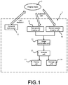
- Fig. 1 is a schematic conceptual diagram schematically illustrating a first embodiment of an imaging apparatus according to the present technology.
- the imaging apparatus 1 at least includes a coherent light source 11, a first speckle imaging unit 12, a second speckle imaging unit 13, and an image combination unit 14.
- the imaging apparatus may further include an analysis unit 15, a storage unit 16, a display unit 17, and the like. Each component will be described in detail below.
- the coherent light source 11 irradiates the imaging object O with coherent light.
- the coherent light emitted from the coherent light source 11 denotes light in which the phase relationship between light waves at arbitrary two points in a light flux is invariable and constant in terms of time and, thus, even in the case of dividing the light flux by an arbitrary method and, after that, providing a large optical path difference and overlaying the divided light fluxes again, perfect coherency is exhibited.
- the type of the coherent light source 11 is not particularly limited as long as the effect of the present technology is not impaired.
- laser light and the like may be exemplified.
- the coherent light source 11 that emits laser light an argon ion (Ar) laser, a helium-neon (He-Ne) laser, a dye laser, a krypton (Cr) laser, a semiconductor laser, a solid-state laser in which a semiconductor laser and a wavelength conversion optical element are combined, and the like may be exemplified, and one or two or more types thereof may be used freely in combination.
- the imaging apparatus 1 includes a first speckle imaging unit 12.
- speckle imaging is performed on the basis of scattered light obtained from the imaging object O irradiated with the coherent light. Note that, in the following description, a speckle image captured by the first speckle imaging unit 12 will be referred to as "first speckle image”.
- the imaging method performed by the first speckle imaging unit 12 is not particularly limited as long as the effect of the present technology is not impaired, and one or two or more known imaging methods may be selected and used freely in combination.
- an imaging method using an imaging element such as a charge coupled device (CCD) or a complementary metal oxide semiconductor (CMOS) sensor may be exemplified.
- CCD charge coupled device
- CMOS complementary metal oxide semiconductor
- the first speckle imaging unit 12 automatically measures the luminance distribution of the speckle in the captured image.
- the luminance distribution of the speckle in the captured image is measured using, for example, a luminance meter.
- the method of measuring the luminance distribution is not particularly limited as long as the effect of the present technology is not impaired, and one or two or more known calculation methods may be selected and used freely in combination.
- the first speckle imaging unit 12 for example, an image or the like in which a pseudo blood vessel through which pseudo blood flows is mapped on the basis of the speckle luminance distribution is generated.
- the speckle is a random interference/diffraction pattern as described above, when the scattering fluid such as blood moves or changes with time, the speckle also varies with time. For this reason, it is possible to observe the boundary between the fluid and other portions.
- the first speckle imaging unit 12 may have a configuration where, for example, equalization is performed by using a plurality of speckle images to reduce irregularity of the speckle image.
- the imaging apparatus 1 according to the present technology includes a second speckle imaging unit 13.
- this second speckle imaging unit 13 similar to the first speckle imaging unit 12, speckle imaging is performed on the basis of scattered light obtained from the imaging object O irradiated with the coherent light.
- the imaging apparatus 1 according to the present technology has a structure of a so-called pantoscopic imaging apparatus.
- each imaging unit is configured to capture a speckle image.
- the imaging apparatus 1 has a so-called stereo camera structure, in which the second speckle imaging unit 13 and the first speckle imaging unit 12 capture the imaging object O in different directions.
- the structure of the second speckle imaging unit 13 is the same as the structure of the first speckle imaging unit 12, and description thereof will thus be omitted. Note that, in the following description, a speckle image captured by the second speckle imaging unit 13 will be referred to as "second speckle image”.
- the imaging apparatus 1 includes an image combination unit 14.
- the image combination unit 14 combines the first speckle image and the second speckle image. Specifically, for example, the image combination unit 14 combines image information (for example, number of pixels, color tone of pixels, etc.) of the first speckle image and image information of the second speckle image to thereby generate a single speckle combined image.
- image information for example, number of pixels, color tone of pixels, etc.
- the image combination unit 14 corrects the luminance value of the speckle combined image on the basis of the luminance values of the speckle images such that the luminance distribution of the speckle combined image is uniform.
- the correcting method is not particularly limited, and a known method may be used.
- the imaging apparatus 1 may include an analysis unit 15 as necessary.
- the analysis unit 15 analyzes the state of the imaging object O by using the speckle combined image generated by the image combination unit 14.
- the imaging object O is a blood vessel
- the scattering fluid such as blood moves or changes with time
- the speckle also varies with time accordingly. Therefore, the speed of the blood flow can be measured by the analysis unit 15.
- analysis unit 15 is not necessarily included in the imaging apparatus 1 according to the present technology, and the state of the imaging object O may also be analyzed by using an external analysis device or the like.
- the imaging apparatus 1 may further include a storage unit 16 that stores the speckle image captured by the first speckle imaging unit 12, the non-speckle image captured by the second speckle imaging unit 13, the speckle combined image generated by the image combination unit 14, the analysis result analyzed by the analysis unit 15, and the like.
- This storage unit 16 is not necessarily included in the imaging apparatus 1 according to the present technology, but the imaging apparatus may be connected to, for example, an external storage device to store the speckle image and the like.
- the imaging apparatus 1 may further include a display unit 17 that displays the speckle image captured by the first speckle imaging unit 12, the non-speckle image captured by the second speckle imaging unit 13, the combined image generated by the image combination unit 14, the analysis result analyzed by the analysis unit 15, and the like.
- the display unit 17 may display the luminance distribution measured by the first speckle imaging unit 12 so as to be superimposed on the speckle image.
- the display unit 17 is not necessarily included in the imaging apparatus 1 according to the present technology, and light irradiation may be performed on the imaging object O by using, for example, an external monitor or the like.
- the imaging apparatus 1 may set various objects as the imaging objects O
- the imaging apparatus 1 can be suitably used for imaging an object containing, for example, a fluid as the imaging object O. Due to the nature of the speckle, the speckle is not easily generated from the fluid. For this reason, when the object containing a fluid is imaged by using the imaging apparatus 1 according to the present technology, a boundary between the fluid and other portions, a flow speed of the fluid and the like can be obtained.
- a biological object may be exemplified as the imaging object O, and blood may be exemplified as a fluid.
- the imaging apparatus 1 according to the present technology is mounted on a surgical microscope, a surgical endoscope, or the like, surgery can be performed while identifying the position of a blood vessel. Therefore, it is possible to carry out safer and highly accurate surgery, and thus, it is possible to contribute to further development of medical technology.
- the first speckle imaging unit 12 and the second speckle imaging unit 13, i.e., two imaging units, are provided, and a so-called stereo camera structure is employed. So there is parallax between the two imaging units.
- wavefront information of the imaging object O that reaches the first speckle imaging unit 12 is different from wavefront information of the imaging object O that reaches the second speckle imaging unit 13.
- the image noise resulting from the speckle shape of the first speckle image is different from the image noise resulting from the speckle shape of the second speckle image.
- the imaging apparatus 1 includes the image combination unit 14.
- the image combination unit 14 combines the first speckle image and the second speckle image, and the noise is thus averaged. So the image noise of the speckle combined image may be reduced. As a result, it is possible to acquire the speckle combined image with high resolution.
- both the imaging units 12 and 13 capture speckles. So, even if one imaging unit does not work, the other imaging unit may capture a speckle. As a result, a user may keep on observing the imaging object O. Therefore, for example, if the imaging apparatus 1 of the present technology is used for medical operations, even if one imaging unit does not work, a doctor may continue the operation.
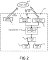
- Fig. 2 is a schematic conceptual diagram illustrating an imaging apparatus according to a second embodiment to which the present technology can be applied.
- the imaging apparatus 201 according to the second embodiment is different from the imaging apparatus 1 according to the first embodiment in that the image combination unit 14 includes an image superimposing unit 21.
- the embodiments are the same in that at least the coherent light source 11, the first the first speckle imaging unit 12, the second speckle imaging unit 13, and the image combination unit 14 are included, and furthermore, the embodiments are the same in that the analysis unit 15, the storage unit 16, the display unit 17, and the like may be included as necessary.
- the description of the configuration common to the imaging apparatus 1 according to the first embodiment will be omitted.
- the image superimposing unit 21 will be described.
- the imaging apparatus 201 includes an image superimposing unit 21.
- the image combination unit 14 combines the first speckle image and the second speckle image
- the image superimposing unit 21 superimposes image information of the speckle images.
- the superimposing method is not particularly limited, and a known method may be used. For example, a method of adding and averaging speckle images may be used.
- Effects of the imaging apparatus 201 including the image superimposing unit 21 of the second embodiment are the same as effects of the imaging apparatus 1 of the first embodiment. Especially, since the imaging apparatus 201 includes the image superimposing unit 21, by combining the first speckle image and the second speckle image, the noise is averaged. Therefore the image noise of the the speckle combined image may be reduced. As a result, it is possible to acquire the speckle combined image with high resolution.
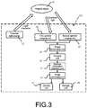
- Fig. 3 is a schematic conceptual diagram of an imaging apparatus according to a third embodiment to which the present technology is applied.
- the imaging apparatus 301 according to the third embodiment is different from the imaging apparatus 1 according to the first embodiment in that the imaging apparatus 1 includes a parallax information obtaining unit 31 that obtains parallax information between the two imaging units 12 and 13, the analysis unit 15 includes an image processing unit 32, and the display unit 17 three-dimensionally displays the imaging object O in a stereo system.
- the embodiments are the same in that at least the coherent light source 11, the first first speckle imaging unit 12, the second speckle imaging unit 13, and the image combination unit 14 are included, and furthermore, the embodiments are the same in that the analysis unit 15, the storage unit 16, the display unit 17, and the image superimposing unit 21 may be included as necessary.
- the description of the configuration common to the imaging apparatus 1 according to the first embodiment will be omitted.
- the parallax information obtaining unit 31 and the image processing unit 32 will be described.
- the imaging apparatus of the present technology includes the first speckle imaging unit 12 and the second speckle imaging unit 13, i.e., two imaging units, and employs a so-called stereo camera structure. So there is parallax between the two imaging units.
- the parallax information obtaining unit 31 obtains information about the parallax.
- the parallax information means, for example, numerical data of parallax of each speckle image.
- the method of obtaining information of the parallax information obtaining unit 31 is not particularly limited, and a known method may be used.
- the analysis unit 15 includes the image processing unit 32.
- the image processing unit 32 is configured to obtain state information of the imaging object O on the basis of parallax information obtained by the parallax information obtaining unit 31.
- the display unit 17 three-dimensionally displays the imaging object O in a stereo system.
- the display unit 17 may three-dimensionally display the imaging object O only with horizontal parallax because vertical parallax is not captured.
- the display unit 17 may three-dimensionally display a speckle combined image only with horizontal parallax. Therefore, the imaging object O may be observed not only two-dimensionally but also three-dimensionally. Therefore, for example, when imaging blood that is scattering fluid, three-dimensional information of a blood vessel in which the blood flows may be obtained.
- Fig. 4 is a schematic conceptual diagram of an imaging apparatus according to a fourth embodiment to which the present technology is applied.
- the imaging apparatus 301 according to the fourth embodiment is different from the imaging apparatus 1 according to the first embodiment in that each of the first speckle imaging unit 12 and the second speckle imaging unit 13 includes a pixel unit 41.
- the embodiments are the same in that at least the coherent light source 11, the first speckle imaging unit 12, the second speckle imaging unit 13, and the image combination unit 14 are included, and furthermore, the embodiments are the same in that the analysis unit 15, the storage unit 16, the display unit 17, and the like may be included as necessary.
- the description of the configuration common to the imaging apparatus 1 according to the first embodiment will be omitted.
- the pixel unit 41 will be described.
- each of the speckle imaging units 12 and 13 includes the pixel unit 41.
- Each pixel unit 41 includes pixels each corresponding to each color component of a plurality of color components arrayed on a plane regularly.
- the structure of the pixel unit 41 is not particularly limited. However, in order to increase the resolution of each captured speckle image, the Bayer matrix structure, which includes pixels corresponding to R, G, and B color components, may be preferably used.
- the spectral sensitivity of each pixel with respect to the wavelength of speckle lighting is obtained. Then, the spectral sensitivity of each pixel may be corrected easily such that the spectral sensitivity of the pixels is uniform.
- the solid line shows the relative spectral sensitivity of the blue (B) color component
- the dashed-chain line shows the relative spectral sensitivity of the green (G) color component
- the double-dashed-chain line shows the relative spectral sensitivity of the red color component.
- each of the speckle imaging units 12 and 13 includes the pixel unit 41.
- each pixel unit 41 has the Bayer matrix structure including pixels corresponding to R, G, and B color components.
- the spectral sensitivity of each of R, G, and B pixels may be corrected such that the spectral sensitivity is uniform.
- the present technology also provides an imaging system.
- Fig. 6 is a schematic conceptual diagram schematically illustrating an imaging system 501 according to the first embodiment of the present technology.
- the imaging system 501 includes at least a coherent light source 110, a first speckle imaging device 120, a second speckle imaging device 130, and an image combination device 140.
- the imaging system 501 may further include an analysis device 150, a storage device 160, a display device 170, an image superimposing device 180, a parallax information obtaining device 190, and an image processing device 210. Each device will be described below.
- the type of the coherent light source 110 is not particularly limited as long as the effect of the present technology is not impaired.
- laser light and the like may be exemplified.
- the coherent light source 110 that emits laser light an argon ion (Ar) laser, a helium-neon (He-Ne) laser, a dye laser, a krypton (Cr) laser, a semiconductor laser, a solid-state laser in which a semiconductor laser and a wavelength conversion optical element are combined, and the like may be exemplified, and one or two or more types thereof may be used freely in combination.
- the imaging system 501 includes a first speckle imaging device 120.
- speckle imaging device 130 speckle imaging is performed on the basis of scattered light obtained from the imaging object O irradiated with the coherent light.
- a speckle image captured by the first speckle imaging device 120 will be referred to as "first speckle image”.
- the imaging method performed by the first speckle imaging device 120 is not particularly limited as long as the effect of the present technology is not impaired, and one or two or more known imaging methods may be selected and used freely in combination.
- an imaging method using an imaging element such as a charge coupled device (CCD) or a complementary metal oxide semiconductor (CMOS) sensor may be exemplified.
- CCD charge coupled device
- CMOS complementary metal oxide semiconductor
- the first speckle imaging device 120 may include a pixel unit (not shown).
- the pixel unit includes pixels each corresponding to each color component of a plurality of color components arrayed on a plane regularly.
- the structure of the pixel unit is not particularly limited. However, in order to increase the resolution of each captured speckle image, the Bayer matrix structure, which includes pixels corresponding to R, G, and B color components, may be preferably used.
- the spectral sensitivity of each pixel with respect to the wavelength of speckle lighting is obtained. Then, the spectral sensitivity of each pixel may be corrected easily such that the spectral sensitivity is uniform.
- the first speckle imaging device 120 may be configured to measure the luminance distribution of the speckle in the captured image.
- the luminance distribution of the speckle in the captured image is measured by using, for example, a luminance meter.
- the method of measuring the luminance distribution is not particularly limited as long as the effect of the present technology is not impaired, and one or two or more known calculation methods may be selected and used freely in combination.
- the first speckle imaging device 120 for example, an image or the like in which a pseudo blood vessel through which pseudo blood flows is mapped on the basis of the speckle luminance distribution is generated.
- the speckle is a random interference/diffraction pattern as described above, when the scattering fluid such as blood moves or changes with time, the speckle also varies with time. For this reason, it is possible to observe the boundary between the fluid and other portions.
- the first speckle imaging device 120 may have a configuration where, for example, equalization is performed by using a plurality of speckle images to reduce irregularity of the speckle image.
- the imaging system 501 according to the present technology includes a second speckle imaging device 130.
- the second speckle imaging device 130 similar to the first speckle imaging device 120, a speckle is captured on the basis of the scattered light obtained from the imaging object O which is irradiated with the coherent light.
- the imaging system 501 according to the present technology has a structure of a so-called pantoscopic imaging apparatus.
- each imaging unit is configured to capture a speckle image.
- the imaging system 501 has a so-called stereo camera system structure, in which the second speckle imaging device 130 and the first speckle imaging device 120 capture the imaging object O in different directions.
- the structure of the second speckle imaging device 130 is the same as the structure of the first speckle imaging device 120, and description thereof will thus be omitted. Note that, in the following description, a speckle image captured by the second speckle imaging device 130 will be referred to as "second speckle image”.
- the imaging system 501 includes an image combination device 140 as necessary.
- the image combination device 140 combines a first speckle image and a second speckle image.
- image information for example, number of pixels, color tone of pixels, etc.
- image information of the second speckle image to thereby generate a single speckle combined image.
- the image combination device 140 may correct the luminance value of the speckle combined image on the basis of the luminance values of the speckle images such that the luminance distribution of the speckle combined image is uniform.
- the correcting method is not particularly limited, and a known method may be used.
- the imaging system 501 may include an analysis device 150 as necessary.
- the analysis device 150 analyzes the state of the imaging object O by using the speckle combined image generated by the image combination device 140.
- the imaging object O is a blood vessel
- the scattering fluid such as blood moves or changes with time
- the speckle also varies with time accordingly. Therefore, the speed of the blood flow can be measured by the analysis device 150.
- the analysis device 150 is not necessarily included in the imaging system 501 according to the present technology, and the state of the imaging object O may also be analyzed by using an external analysis device or the like.
- the imaging system 501 may further include a storage device 160 that stores the speckle image captured by the first speckle imaging device 120, the non-speckle image captured by the second speckle imaging device 130, the speckle combined image generated by the image combination device 140, the analysis result analyzed by the analysis device 150, and the like.
- the storage device 160 is not necessarily included in the imaging system 501 according to the present technology, but the imaging system may be connected to, for example, an external storage device to store the speckle image and the like.
- the imaging system 501 may further include a display device 170 that displays the speckle image captured by the first speckle imaging device 120, the non-speckle image captured by the second speckle imaging device 130, the speckle combined image generated by the image combination device 140, the analysis result analyzed by the analysis device 150, and the like.
- the display device 170 may display the luminance distribution measured by the first speckle imaging device 120 so as to be superimposed on the speckle image.
- the display device 170 is not necessarily included in the imaging system 501 according to the present technology, and light irradiation may be performed on the imaging object O by using, for example, an external monitor or the like.
- the imaging system 501 may include an image superimposing device 180 as necessary.
- the image combination device 140 combines the first speckle image and the second speckle image
- the image superimposing device 180 superimposes image information of the speckle images.
- the superimposing method is not particularly limited, and a known method may be used. For example, a method of adding and averaging speckle images may be used.
- the imaging system 501 of the present technology includes the first speckle imaging device 120 and the second speckle imaging device 130, i.e., two imaging devices, and employs a so-called stereo camera structure. So there is parallax between the two imaging devices.
- the parallax information obtaining device 190 obtains information about the parallax.
- the parallax information means, for example, numerical data of parallax of each speckle image.
- the method of obtaining information of the parallax information obtaining device 190 is not particularly limited, and a known method may be used.
- the imaging system 501 if the imaging system 501 includes the parallax information obtaining device 190, the imaging system 501 preferably includes the image processing device 210.
- the image processing device 210 is configured to obtain state information of the imaging object O on the basis of parallax information obtained by the parallax information obtaining device 190.
- the display device 170 three-dimensionally displays the imaging object O in a stereo system.
- the display device 170 may three-dimensionally display the imaging object O only with horizontal parallax because vertical parallax is not captured.
- the first speckle imaging device 120 and the second speckle imaging device 130 i.e., two imaging devices, are provided, and a so-called stereo camera structure is employed. So there is parallax between the two imaging devices. As a result, wavefront information of the imaging object O that reaches the first speckle imaging device 120 is different from wavefront information of the imaging object O that reaches the second speckle imaging device 130.
- the image noise resulting from the speckle shape of the first speckle image is different from the image noise resulting from the speckle shape of the second speckle image.
- the imaging system 501 includes the image combination device 140.
- the image combination device 140 combines the first speckle image and the second speckle image, and the noise is thus averaged. So the image noise of the speckle combined image may be reduced. As a result, it is possible to acquire the speckle combined image with high resolution.
- both the imaging devices capture speckles. So, even if one imaging device does not work, the other imaging device may capture a speckle. As a result, a user may keep on observing the imaging object O. Further, even if the imaging system 501 according to the present technology includes the image superimposing device 180, it is possible to acquire the speckle combined image with high resolution.
- the imaging system 501 includes the parallax information obtaining device 190 and the image processing device 210, the display device 170 may three-dimensionally display a speckle combined image only with horizontal parallax. Therefore, the imaging object O may be observed not only two-dimensionally but also three-dimensionally. Therefore, for example, when imaging blood that is scattering fluid, three-dimensional information of a blood vessel in which the blood flows may be obtained.
- each pixel unit 41 has the Bayer matrix structure including pixels corresponding to R, G, and B color components.
- the spectral sensitivity of each of R, G, and B pixels may be corrected such that the spectral sensitivity is uniform.
- the present technology also provides an imaging method.
- Fig. 7 is a flowchart of an imaging method according to the present technology.
- the imaging method according to the first embodiment includes at least a coherent light irradiating step, a first speckle imaging step, a second speckle imaging step, and an image combining step.
- the imaging method may further include an image superimposing step, a parallax information obtaining step, and an image processing step.
- the analyzing step, the storing step, the displaying step, the image superimposing step, the parallax information obtaining step, and the image processing step are also illustrated, but as described above, these steps are not necessary steps. Therefore, these steps may not be performed in the imaging method according to the present technology. However, among the aforementioned steps, since a predetermined effect is exhibited by including the analyzing step, the storing step, the displaying step, the image superimposing step, the parallax information obtaining step, and the image processing step, it is desirable that these steps are included. The aforementioned steps will be described below in the order of executing the imaging method according to the present technology.
- the imaging object O is irradiated with coherent light (coherent light irradiating step S1).
- the type of the coherent light source is not particularly limited as long as the effect of the present technology is not impaired.
- laser light and the like may be exemplified.
- an argon ion (Ar) laser, a helium-neon (He-Ne) laser, a dye laser, a krypton (Cr) laser, a semiconductor laser, a solid-state laser in which a semiconductor laser and a wavelength conversion optical element are combined, and the like may be exemplified, and one or two or more types thereof may be used freely in combination.
- a first speckle image is captured.
- the imaging method in the first speckle imaging step S2 is not particularly limited, and one or two or more known imaging methods may be selected and used freely in combination.
- an imaging method using an imaging element such as a charge coupled device (CCD) or a complementary metal oxide semiconductor (CMOS) sensor may be exemplified.
- CCD charge coupled device
- CMOS complementary metal oxide semiconductor
- the first speckle imaging step S2 may include a sensitivity correcting step S21 using the Bayer matrix including pixels corresponding to R, G, and B color components.
- the imaging method of the present technology after capturing a first speckle image, a second speckle image is captured.
- the imaging method of the present technology employs a so-called stereo system, in which the first speckle image and the second speckle image of the imaging object O are captured in different directions.
- the imaging method in the second speckle imaging step is the same as the imaging method in the first speckle imaging step, and description thereof will thus be omitted.
- the second speckle imaging step S3 may include the sensitivity correcting step using the Bayer matrix.
- the imaging method according to the present technology includes an image combining step S4 of combining the first speckle image captured in the first speckle imaging step S2 and the non-speckle image captured in the second speckle imaging step S3.
- the image combining step S4 includes combining image information (for example, number of pixels, color tone of pixels, etc.) of the first speckle image and image information of the second speckle image to thereby generate a single speckle combined image.
- image information for example, number of pixels, color tone of pixels, etc.
- the image combining step S4 may include correcting the luminance value of the speckle combined image on the basis of the luminance values of the speckle images such that the luminance distribution of the speckle combined image is uniform.
- the correcting method is not particularly limited, and a known method may be used.
- the image combining step S4 may, without any problem, include superimposing the first speckle image and the second speckle image on each other to thereby generate a speckle superimposed image.
- the superimposing method is not particularly limited, and a known method may be used. For example, a method of adding and averaging speckle images may be used.
- FIG. 8 is a flowchart showing the analyzing step S5 in detail.
- the state of the imaging object O is analyzed by using the speckle combined image generated in the image combining step S4.
- the imaging object O is a blood vessel
- the scattering fluid such as blood moves or changes with time
- the speckle also varies with time accordingly. Therefore, the speed of the blood flow can be measured in the analyzing step S5.
- the analyzing step S5 of the present technology may include a parallax information obtaining step S51 and an image processing step 52. Those steps will be described below.
- the imaging method of the present technology employs a stereo system, in which a first speckle image and a second speckle image of the imaging object O are captured in different directions. So there is parallax between the first speckle image and the second speckle image.
- parallax information obtained in the first speckle imaging step S2 and the second speckle imaging step S3 is obtained.
- the parallax information means, for example, numerical data of parallax of each speckle image.
- the method of obtaining information in the parallax information obtaining step S51 is not particularly limited, and a known method may be used.
- an image processing step S52 of obtaining state information of the imaging object O on the basis of the obtained parallax information is executed.
- the imaging method of the present technology employs the stereo system, in the image processing step S52, it is possible to analyze three-dimensional information of the imaging object O only with horizontal parallax out of the parallax information obtained in the parallax information obtaining step.
- the analyzing step S5 is completed.
- the imaging method according to the present technology may include, as necessary, a storing step S6.
- the storing step S6 includes storing the speckle image captured in the first speckle imaging step S2, the non-speckle image captured in the second speckle imaging step S3, the speckle combined image generated in the image combining step S4, the analysis result analyzed in the analyzing step S5, and the like.
- the imaging method according to the present technology may include a displaying step S7 as necessary.
- the speckle image captured in the first speckle imaging step S2 the non-speckle image captured in the second speckle imaging step S3, the speckle combined image generated in the image combining step S4, an analysis result analyzed in the analyzing step S5, and the like may be displayed.
- the imaging method of the present technology includes the first speckle imaging step S2 and the second speckle imaging step S3 and employs a so-called stereo system, there is parallax between two speckle images.
- the image noise resulting from the speckle shape of the first speckle image is different from the image noise resulting from the speckle shape of the second speckle image.
- the imaging method of the present technology includes the image combining step S4.
- the image combining step S4 includes combining the first speckle image and the second speckle image, and the noise is thus averaged. So the image noise of the speckle combined image may be reduced. As a result, it is possible to acquire the speckle combined image with high resolution.
- the imaging method of the present technology includes the parallax information obtaining step S51 and the image processing step S52, it is possible to three-dimensionally display a speckle combined image only with horizontal parallax. Therefore, the imaging object O may be observed not only two-dimensionally but also three-dimensionally. Therefore, for example, when imaging blood that is scattering fluid, three-dimensional information of a blood vessel in which the blood flows may be obtained.
- each speckle imaging step may include the sensitivity correcting step S21 using the Bayer matrix.
- the spectral sensitivities of R, G, and B pixels are corrected such that the spectral sensitivity is uniform.
Landscapes
- Health & Medical Sciences (AREA)
- Life Sciences & Earth Sciences (AREA)
- Engineering & Computer Science (AREA)
- Signal Processing (AREA)
- Physics & Mathematics (AREA)
- Surgery (AREA)
- Public Health (AREA)
- General Health & Medical Sciences (AREA)
- Pathology (AREA)
- Biomedical Technology (AREA)
- Heart & Thoracic Surgery (AREA)
- Medical Informatics (AREA)
- Molecular Biology (AREA)
- Biophysics (AREA)
- Animal Behavior & Ethology (AREA)
- Veterinary Medicine (AREA)
- Multimedia (AREA)
- Physiology (AREA)
- Hematology (AREA)
- Cardiology (AREA)
- Theoretical Computer Science (AREA)
- Computer Vision & Pattern Recognition (AREA)
- Nuclear Medicine, Radiotherapy & Molecular Imaging (AREA)
- Radiology & Medical Imaging (AREA)
- General Physics & Mathematics (AREA)
- Vascular Medicine (AREA)
- Psychiatry (AREA)
- Artificial Intelligence (AREA)
- Optics & Photonics (AREA)
- Computing Systems (AREA)
- Investigating Or Analysing Materials By Optical Means (AREA)
- Studio Devices (AREA)
Claims (6)
- Appareil d'imagerie (1), comprenant :une source de lumière cohérente (11) qui irradie un objet d'imagerie avec une lumière cohérente;une première unité d'imagerie de tavelures (12) qui capture une image de tavelures obtenue à partir de la lumière diffusée de l'objet d'imagerie irradié avec la lumière cohérente;une seconde unité d'imagerie de tavelures (13) qui capture une image de tavelures obtenue à partir de la lumière diffusée de l'objet d'imagerie irradié avec la lumière cohérente; etune unité de combinaison d'images (14) qui combine la première image de tavelures capturée par la première unité d'imagerie de tavelures et la seconde image de tavelures capturée par la seconde unité d'imagerie de tavelures, dans lequell'unité de combinaison d'images corrige la valeur de luminance de l'image combinée de tavelures sur la base des valeurs de luminance de la première image de tavelures et de la seconde image de tavelures de telle sorte que la distribution de luminance de l'image combinée de tavelures soit uniforme.
- Appareil d'imagerie selon la revendication 1, comprenant en outre :
une unité de superposition d'images (21) qui superpose des informations d'image de la première image de tavelures et des informations d'image de la seconde image de tavelures les unes sur les autres. - Appareil d'imagerie selon la revendication 1, comprenant en outre :une unité d'obtention d'informations de parallaxe (31) qui obtient des informations de parallaxe générées entre la première unité d'imagerie de tavelures et la seconde unité d'imagerie de tavelures; etune unité de traitement d'images (32) qui obtient des informations d'état de l'objet d'imagerie sur la base des informations de parallaxe obtenues par l'unité d'obtention d'informations de parallaxe.
- Appareil d'imagerie selon la revendication 1, dans lequel
chacune de la première unité d'imagerie de tavelures et de la seconde unité d'imagerie de tavelures comprend une unité de pixels (41), l'unité de pixels comprenant des pixels correspondant chacun à chaque composante de couleur d'une pluralité de composantes de couleur disposées sur un plan de manière régulière. - Appareil d'imagerie selon la revendication 4, dans lequel
l'unité de pixels est une unité de pixels de la matrice de Bayer. - Procédé d'imagerie, comprenant :une étape d'irradiation de lumière cohérente consistant à irradier un objet d'imagerie avec une lumière cohérente;une première étape d'imagerie de premières tavelures consistant à capturer une image de tavelures obtenue à partir de la lumière diffusée de l'objet d'imagerie irradié avec la lumière cohérente;une seconde étape d'imagerie de premières tavelures consistant à capturer une image de tavelures obtenue à partir de la lumière diffusée de l'objet d'imagerie irradié avec la lumière cohérente; etune étape de combinaison d'images consistant à combiner la première image de tavelures capturée dans la première étape d'imagerie de premières tavelures et la seconde image de tavelures capturée dans la seconde étape d'imagerie de premières tavelures, dans lequell'étape de combinaison d'images corrige la valeur de luminance de l'image combinée de tavelures sur la base des valeurs de luminance de la première image de tavelures et de la seconde image de tavelures de telle sorte que la distribution de luminance de l'image combinée de tavelures soit uniforme.
Applications Claiming Priority (2)
| Application Number | Priority Date | Filing Date | Title |
|---|---|---|---|
| JP2016024859 | 2016-02-12 | ||
| PCT/JP2016/083905 WO2017138210A1 (fr) | 2016-02-12 | 2016-11-16 | Appareil de capture d'image, procédé de capture d'image et système de capture d'image |
Publications (3)
| Publication Number | Publication Date |
|---|---|
| EP3416366A1 EP3416366A1 (fr) | 2018-12-19 |
| EP3416366A4 EP3416366A4 (fr) | 2019-02-20 |
| EP3416366B1 true EP3416366B1 (fr) | 2021-03-03 |
Family
ID=59563209
Family Applications (1)
| Application Number | Title | Priority Date | Filing Date |
|---|---|---|---|
| EP16889911.0A Active EP3416366B1 (fr) | 2016-02-12 | 2016-11-16 | Appareil de capture d'image et procédé de capture d'image |
Country Status (3)
| Country | Link |
|---|---|
| US (1) | US11025812B2 (fr) |
| EP (1) | EP3416366B1 (fr) |
| WO (1) | WO2017138210A1 (fr) |
Families Citing this family (6)
| Publication number | Priority date | Publication date | Assignee | Title |
|---|---|---|---|---|
| JPWO2020045014A1 (ja) * | 2018-08-28 | 2021-08-12 | ソニーグループ株式会社 | 医療システム、情報処理装置及び情報処理方法 |
| CN110505387B (zh) * | 2019-08-29 | 2021-06-11 | Oppo广东移动通信有限公司 | 成像系统、终端和图像获取方法 |
| NL2026505B1 (en) * | 2020-09-18 | 2022-05-23 | Limis Dev B V | Motion-compensated laser speckle contrast imaging |
| CN113240746B (zh) * | 2021-04-19 | 2023-07-04 | 福建新大陆自动识别技术有限公司 | 基于理想成像平面的散斑结构光标定方法和设备 |
| CN113965679B (zh) * | 2021-10-19 | 2022-09-23 | 合肥的卢深视科技有限公司 | 深度图获取方法、结构光相机、电子设备及存储介质 |
| CN113936050B (zh) * | 2021-10-21 | 2022-08-12 | 合肥的卢深视科技有限公司 | 散斑图像生成方法、电子设备及存储介质 |
Family Cites Families (9)
| Publication number | Priority date | Publication date | Assignee | Title |
|---|---|---|---|---|
| JP3005698B2 (ja) | 1991-09-10 | 2000-01-31 | 株式会社小野測器 | スペックルノイズの除去装置 |
| US6097477A (en) * | 1994-05-27 | 2000-08-01 | American Research Corporation Of Virginia | Laser speckle strain and deformation sensor using linear array image cross-correlation method for specifically arranged triple-beam triple-camera configuration |
| US7234937B2 (en) * | 1999-11-30 | 2007-06-26 | Orametrix, Inc. | Unified workstation for virtual craniofacial diagnosis, treatment planning and therapeutics |
| US8571303B2 (en) * | 2008-11-25 | 2013-10-29 | Nec System Technologies, Ltd. | Stereo matching processing system, stereo matching processing method and recording medium |
| GB0921477D0 (en) * | 2009-12-08 | 2010-01-20 | Moor Instr Ltd | Apparatus for measuring blood parameters |
| US10776533B2 (en) * | 2010-07-12 | 2020-09-15 | 3Shape A/S | 3D modeling of a dental restoration using textural features |
| KR101767094B1 (ko) * | 2012-12-03 | 2017-08-31 | 한화테크윈 주식회사 | 영상 처리 장치 및 방법 |
| JP6100089B2 (ja) | 2013-05-17 | 2017-03-22 | キヤノン株式会社 | 画像処理装置、画像処理方法およびプログラム |
| CN104864819B (zh) * | 2015-01-19 | 2017-08-01 | 华中科技大学 | 一种基于数字散斑的高速三维应变测量方法 |
-
2016
- 2016-11-16 US US16/067,662 patent/US11025812B2/en active Active
- 2016-11-16 EP EP16889911.0A patent/EP3416366B1/fr active Active
- 2016-11-16 WO PCT/JP2016/083905 patent/WO2017138210A1/fr active Application Filing
Non-Patent Citations (1)
| Title |
|---|
| None * |
Also Published As
| Publication number | Publication date |
|---|---|
| WO2017138210A1 (fr) | 2017-08-17 |
| US11025812B2 (en) | 2021-06-01 |
| US20200267305A1 (en) | 2020-08-20 |
| EP3416366A4 (fr) | 2019-02-20 |
| EP3416366A1 (fr) | 2018-12-19 |
Similar Documents
| Publication | Publication Date | Title |
|---|---|---|
| EP3416366B1 (fr) | Appareil de capture d'image et procédé de capture d'image | |
| US10681259B2 (en) | Imaging apparatus, imaging method, and imaging system | |
| EP3438646A1 (fr) | Dispositif d'imagerie et procédé d'imagerie | |
| US9095255B2 (en) | Method and device for locating function-supporting tissue areas in a tissue region | |
| EP3385723B1 (fr) | Dispositif de traitement d'informations, système d'imagerie de tavelures et procédé de traitement d'informations | |
| WO2006111836A1 (fr) | Instrument et procede de visualisation de perfusion a grande vitesse | |
| JP2008542758A (ja) | スペクトルコード化ヘテロダイン干渉法を画像化に使用可能なシステム、方法、及び装置 | |
| US20070100245A1 (en) | Laser blood flow imaging apparatus | |
| US20190099089A1 (en) | Image analysis apparatus and image analysis method | |
| JP6507509B2 (ja) | 流路撮像装置及び流路撮像方法 | |
| US20180321081A1 (en) | Speckle imaging device, speckle imaging system, and speckle imaging method | |
| WO2018211982A1 (fr) | Dispositif et procédé de traitement d'image, et système de traitement d'image | |
| JP2020536221A (ja) | 表面トポロジおよび関連する色を決定するための装置および方法 | |
| US11391937B2 (en) | Method and device for determining a property of an object | |
| JP2013003386A (ja) | 撮像装置およびバーチャルスライド装置 | |
| US10681283B2 (en) | Imaging system, imaging apparatus, and imaging method | |
| US10551300B2 (en) | Observation apparatus, observation system, data processing apparatus, and program | |
| US20170237885A1 (en) | Method and Apparatus for High Contrast Imaging | |
| Naumov et al. | Estimating the quality of stereoscopic endoscopic systems | |
| US20170352153A1 (en) | Method and apparatus for the morphometric analysis of cells of a corneal endothelium |
Legal Events
| Date | Code | Title | Description |
|---|---|---|---|
| STAA | Information on the status of an ep patent application or granted ep patent |
Free format text: STATUS: THE INTERNATIONAL PUBLICATION HAS BEEN MADE |
|
| PUAI | Public reference made under article 153(3) epc to a published international application that has entered the european phase |
Free format text: ORIGINAL CODE: 0009012 |
|
| STAA | Information on the status of an ep patent application or granted ep patent |
Free format text: STATUS: REQUEST FOR EXAMINATION WAS MADE |
|
| 17P | Request for examination filed |
Effective date: 20180804 |
|
| AK | Designated contracting states |
Kind code of ref document: A1 Designated state(s): AL AT BE BG CH CY CZ DE DK EE ES FI FR GB GR HR HU IE IS IT LI LT LU LV MC MK MT NL NO PL PT RO RS SE SI SK SM TR |
|
| AX | Request for extension of the european patent |
Extension state: BA ME |
|
| RIC1 | Information provided on ipc code assigned before grant |
Ipc: H04N 13/02 20060101ALI20170905BHEP Ipc: H04N 5/238 20060101ALI20170905BHEP Ipc: A61B 1/00 20060101ALI20170905BHEP Ipc: H04N 5/225 20060101AFI20170905BHEP Ipc: H04N 5/232 20060101ALI20170905BHEP |
|
| A4 | Supplementary search report drawn up and despatched |
Effective date: 20190123 |
|
| RIC1 | Information provided on ipc code assigned before grant |
Ipc: H04N 5/232 20060101ALI20190117BHEP Ipc: A61B 5/00 20060101ALI20190117BHEP Ipc: A61B 1/00 20060101ALI20190117BHEP Ipc: H04N 5/238 20060101ALI20190117BHEP Ipc: H04N 5/225 20060101AFI20190117BHEP Ipc: A61B 5/026 20060101ALI20190117BHEP |
|
| DAV | Request for validation of the european patent (deleted) | ||
| DAX | Request for extension of the european patent (deleted) | ||
| GRAP | Despatch of communication of intention to grant a patent |
Free format text: ORIGINAL CODE: EPIDOSNIGR1 |
|
| STAA | Information on the status of an ep patent application or granted ep patent |
Free format text: STATUS: GRANT OF PATENT IS INTENDED |
|
| RIC1 | Information provided on ipc code assigned before grant |
Ipc: H04N 5/232 20060101ALI20200904BHEP Ipc: A61B 5/026 20060101ALI20200904BHEP Ipc: A61B 1/00 20060101ALI20200904BHEP Ipc: H04N 5/225 20060101AFI20200904BHEP Ipc: A61B 5/00 20060101ALI20200904BHEP Ipc: H04N 5/238 20060101ALI20200904BHEP |
|
| INTG | Intention to grant announced |
Effective date: 20200929 |
|
| GRAS | Grant fee paid |
Free format text: ORIGINAL CODE: EPIDOSNIGR3 |
|
| STAA | Information on the status of an ep patent application or granted ep patent |
Free format text: STATUS: GRANT OF PATENT IS INTENDED |
|
| GRAA | (expected) grant |
Free format text: ORIGINAL CODE: 0009210 |
|
| STAA | Information on the status of an ep patent application or granted ep patent |
Free format text: STATUS: THE PATENT HAS BEEN GRANTED |
|
| AK | Designated contracting states |
Kind code of ref document: B1 Designated state(s): AL AT BE BG CH CY CZ DE DK EE ES FI FR GB GR HR HU IE IS IT LI LT LU LV MC MK MT NL NO PL PT RO RS SE SI SK SM TR |
|
| REG | Reference to a national code |
Ref country code: GB Ref legal event code: FG4D |
|
| REG | Reference to a national code |
Ref country code: AT Ref legal event code: REF Ref document number: 1368529 Country of ref document: AT Kind code of ref document: T Effective date: 20210315 Ref country code: CH Ref legal event code: EP |
|
| REG | Reference to a national code |
Ref country code: DE Ref legal event code: R096 Ref document number: 602016053811 Country of ref document: DE |
|
| REG | Reference to a national code |
Ref country code: IE Ref legal event code: FG4D |
|
| REG | Reference to a national code |
Ref country code: LT Ref legal event code: MG9D |
|
| RAP4 | Party data changed (patent owner data changed or rights of a patent transferred) |
Owner name: SONY GROUP CORPORATION |
|
| PG25 | Lapsed in a contracting state [announced via postgrant information from national office to epo] |
Ref country code: HR Free format text: LAPSE BECAUSE OF FAILURE TO SUBMIT A TRANSLATION OF THE DESCRIPTION OR TO PAY THE FEE WITHIN THE PRESCRIBED TIME-LIMIT Effective date: 20210303 Ref country code: GR Free format text: LAPSE BECAUSE OF FAILURE TO SUBMIT A TRANSLATION OF THE DESCRIPTION OR TO PAY THE FEE WITHIN THE PRESCRIBED TIME-LIMIT Effective date: 20210604 Ref country code: FI Free format text: LAPSE BECAUSE OF FAILURE TO SUBMIT A TRANSLATION OF THE DESCRIPTION OR TO PAY THE FEE WITHIN THE PRESCRIBED TIME-LIMIT Effective date: 20210303 Ref country code: NO Free format text: LAPSE BECAUSE OF FAILURE TO SUBMIT A TRANSLATION OF THE DESCRIPTION OR TO PAY THE FEE WITHIN THE PRESCRIBED TIME-LIMIT Effective date: 20210603 Ref country code: BG Free format text: LAPSE BECAUSE OF FAILURE TO SUBMIT A TRANSLATION OF THE DESCRIPTION OR TO PAY THE FEE WITHIN THE PRESCRIBED TIME-LIMIT Effective date: 20210603 Ref country code: LT Free format text: LAPSE BECAUSE OF FAILURE TO SUBMIT A TRANSLATION OF THE DESCRIPTION OR TO PAY THE FEE WITHIN THE PRESCRIBED TIME-LIMIT Effective date: 20210303 |
|
| REG | Reference to a national code |
Ref country code: NL Ref legal event code: MP Effective date: 20210303 |
|
| REG | Reference to a national code |
Ref country code: AT Ref legal event code: MK05 Ref document number: 1368529 Country of ref document: AT Kind code of ref document: T Effective date: 20210303 |
|
| PG25 | Lapsed in a contracting state [announced via postgrant information from national office to epo] |
Ref country code: RS Free format text: LAPSE BECAUSE OF FAILURE TO SUBMIT A TRANSLATION OF THE DESCRIPTION OR TO PAY THE FEE WITHIN THE PRESCRIBED TIME-LIMIT Effective date: 20210303 Ref country code: PL Free format text: LAPSE BECAUSE OF FAILURE TO SUBMIT A TRANSLATION OF THE DESCRIPTION OR TO PAY THE FEE WITHIN THE PRESCRIBED TIME-LIMIT Effective date: 20210303 Ref country code: LV Free format text: LAPSE BECAUSE OF FAILURE TO SUBMIT A TRANSLATION OF THE DESCRIPTION OR TO PAY THE FEE WITHIN THE PRESCRIBED TIME-LIMIT Effective date: 20210303 Ref country code: SE Free format text: LAPSE BECAUSE OF FAILURE TO SUBMIT A TRANSLATION OF THE DESCRIPTION OR TO PAY THE FEE WITHIN THE PRESCRIBED TIME-LIMIT Effective date: 20210303 |
|
| PG25 | Lapsed in a contracting state [announced via postgrant information from national office to epo] |
Ref country code: NL Free format text: LAPSE BECAUSE OF FAILURE TO SUBMIT A TRANSLATION OF THE DESCRIPTION OR TO PAY THE FEE WITHIN THE PRESCRIBED TIME-LIMIT Effective date: 20210303 |
|
| PG25 | Lapsed in a contracting state [announced via postgrant information from national office to epo] |
Ref country code: EE Free format text: LAPSE BECAUSE OF FAILURE TO SUBMIT A TRANSLATION OF THE DESCRIPTION OR TO PAY THE FEE WITHIN THE PRESCRIBED TIME-LIMIT Effective date: 20210303 Ref country code: CZ Free format text: LAPSE BECAUSE OF FAILURE TO SUBMIT A TRANSLATION OF THE DESCRIPTION OR TO PAY THE FEE WITHIN THE PRESCRIBED TIME-LIMIT Effective date: 20210303 Ref country code: SM Free format text: LAPSE BECAUSE OF FAILURE TO SUBMIT A TRANSLATION OF THE DESCRIPTION OR TO PAY THE FEE WITHIN THE PRESCRIBED TIME-LIMIT Effective date: 20210303 Ref country code: AT Free format text: LAPSE BECAUSE OF FAILURE TO SUBMIT A TRANSLATION OF THE DESCRIPTION OR TO PAY THE FEE WITHIN THE PRESCRIBED TIME-LIMIT Effective date: 20210303 |
|
| PG25 | Lapsed in a contracting state [announced via postgrant information from national office to epo] |
Ref country code: IS Free format text: LAPSE BECAUSE OF FAILURE TO SUBMIT A TRANSLATION OF THE DESCRIPTION OR TO PAY THE FEE WITHIN THE PRESCRIBED TIME-LIMIT Effective date: 20210703 Ref country code: PT Free format text: LAPSE BECAUSE OF FAILURE TO SUBMIT A TRANSLATION OF THE DESCRIPTION OR TO PAY THE FEE WITHIN THE PRESCRIBED TIME-LIMIT Effective date: 20210705 Ref country code: RO Free format text: LAPSE BECAUSE OF FAILURE TO SUBMIT A TRANSLATION OF THE DESCRIPTION OR TO PAY THE FEE WITHIN THE PRESCRIBED TIME-LIMIT Effective date: 20210303 Ref country code: SK Free format text: LAPSE BECAUSE OF FAILURE TO SUBMIT A TRANSLATION OF THE DESCRIPTION OR TO PAY THE FEE WITHIN THE PRESCRIBED TIME-LIMIT Effective date: 20210303 |
|
| REG | Reference to a national code |
Ref country code: DE Ref legal event code: R097 Ref document number: 602016053811 Country of ref document: DE |
|
| PLBE | No opposition filed within time limit |
Free format text: ORIGINAL CODE: 0009261 |
|
| STAA | Information on the status of an ep patent application or granted ep patent |
Free format text: STATUS: NO OPPOSITION FILED WITHIN TIME LIMIT |
|
| PG25 | Lapsed in a contracting state [announced via postgrant information from national office to epo] |
Ref country code: ES Free format text: LAPSE BECAUSE OF FAILURE TO SUBMIT A TRANSLATION OF THE DESCRIPTION OR TO PAY THE FEE WITHIN THE PRESCRIBED TIME-LIMIT Effective date: 20210303 Ref country code: AL Free format text: LAPSE BECAUSE OF FAILURE TO SUBMIT A TRANSLATION OF THE DESCRIPTION OR TO PAY THE FEE WITHIN THE PRESCRIBED TIME-LIMIT Effective date: 20210303 Ref country code: DK Free format text: LAPSE BECAUSE OF FAILURE TO SUBMIT A TRANSLATION OF THE DESCRIPTION OR TO PAY THE FEE WITHIN THE PRESCRIBED TIME-LIMIT Effective date: 20210303 |
|
| PGFP | Annual fee paid to national office [announced via postgrant information from national office to epo] |
Ref country code: DE Payment date: 20211020 Year of fee payment: 6 Ref country code: GB Payment date: 20211020 Year of fee payment: 6 |
|
| 26N | No opposition filed |
Effective date: 20211206 |
|
| PG25 | Lapsed in a contracting state [announced via postgrant information from national office to epo] |
Ref country code: SI Free format text: LAPSE BECAUSE OF FAILURE TO SUBMIT A TRANSLATION OF THE DESCRIPTION OR TO PAY THE FEE WITHIN THE PRESCRIBED TIME-LIMIT Effective date: 20210303 |
|
| PG25 | Lapsed in a contracting state [announced via postgrant information from national office to epo] |
Ref country code: IT Free format text: LAPSE BECAUSE OF FAILURE TO SUBMIT A TRANSLATION OF THE DESCRIPTION OR TO PAY THE FEE WITHIN THE PRESCRIBED TIME-LIMIT Effective date: 20210303 |
|
| PG25 | Lapsed in a contracting state [announced via postgrant information from national office to epo] |
Ref country code: IS Free format text: LAPSE BECAUSE OF FAILURE TO SUBMIT A TRANSLATION OF THE DESCRIPTION OR TO PAY THE FEE WITHIN THE PRESCRIBED TIME-LIMIT Effective date: 20210703 |
|
| PG25 | Lapsed in a contracting state [announced via postgrant information from national office to epo] |
Ref country code: MC Free format text: LAPSE BECAUSE OF FAILURE TO SUBMIT A TRANSLATION OF THE DESCRIPTION OR TO PAY THE FEE WITHIN THE PRESCRIBED TIME-LIMIT Effective date: 20210303 |
|
| REG | Reference to a national code |
Ref country code: CH Ref legal event code: PL |
|
| PG25 | Lapsed in a contracting state [announced via postgrant information from national office to epo] |
Ref country code: LU Free format text: LAPSE BECAUSE OF NON-PAYMENT OF DUE FEES Effective date: 20211116 Ref country code: BE Free format text: LAPSE BECAUSE OF NON-PAYMENT OF DUE FEES Effective date: 20211130 |
|
| REG | Reference to a national code |
Ref country code: BE Ref legal event code: MM Effective date: 20211130 |
|
| PG25 | Lapsed in a contracting state [announced via postgrant information from national office to epo] |
Ref country code: LI Free format text: LAPSE BECAUSE OF NON-PAYMENT OF DUE FEES Effective date: 20211130 Ref country code: CH Free format text: LAPSE BECAUSE OF NON-PAYMENT OF DUE FEES Effective date: 20211130 |
|
| PG25 | Lapsed in a contracting state [announced via postgrant information from national office to epo] |
Ref country code: IE Free format text: LAPSE BECAUSE OF NON-PAYMENT OF DUE FEES Effective date: 20211116 |
|
| REG | Reference to a national code |
Ref country code: DE Ref legal event code: R079 Ref document number: 602016053811 Country of ref document: DE Free format text: PREVIOUS MAIN CLASS: H04N0005225000 Ipc: H04N0023000000 |
|
| PG25 | Lapsed in a contracting state [announced via postgrant information from national office to epo] |
Ref country code: FR Free format text: LAPSE BECAUSE OF NON-PAYMENT OF DUE FEES Effective date: 20211130 |
|
| REG | Reference to a national code |
Ref country code: DE Ref legal event code: R119 Ref document number: 602016053811 Country of ref document: DE |
|
| PG25 | Lapsed in a contracting state [announced via postgrant information from national office to epo] |
Ref country code: CY Free format text: LAPSE BECAUSE OF FAILURE TO SUBMIT A TRANSLATION OF THE DESCRIPTION OR TO PAY THE FEE WITHIN THE PRESCRIBED TIME-LIMIT Effective date: 20210303 |
|
| GBPC | Gb: european patent ceased through non-payment of renewal fee |
Effective date: 20221116 |
|
| PG25 | Lapsed in a contracting state [announced via postgrant information from national office to epo] |
Ref country code: HU Free format text: LAPSE BECAUSE OF FAILURE TO SUBMIT A TRANSLATION OF THE DESCRIPTION OR TO PAY THE FEE WITHIN THE PRESCRIBED TIME-LIMIT; INVALID AB INITIO Effective date: 20161116 |
|
| PG25 | Lapsed in a contracting state [announced via postgrant information from national office to epo] |
Ref country code: GB Free format text: LAPSE BECAUSE OF NON-PAYMENT OF DUE FEES Effective date: 20221116 Ref country code: DE Free format text: LAPSE BECAUSE OF NON-PAYMENT OF DUE FEES Effective date: 20230601 |
|
| PG25 | Lapsed in a contracting state [announced via postgrant information from national office to epo] |
Ref country code: MK Free format text: LAPSE BECAUSE OF FAILURE TO SUBMIT A TRANSLATION OF THE DESCRIPTION OR TO PAY THE FEE WITHIN THE PRESCRIBED TIME-LIMIT Effective date: 20210303 |