EP3416260A2 - Motoranordnung mit einem dedizierten spannungsbus - Google Patents
Motoranordnung mit einem dedizierten spannungsbus Download PDFInfo
- Publication number
- EP3416260A2 EP3416260A2 EP18173926.9A EP18173926A EP3416260A2 EP 3416260 A2 EP3416260 A2 EP 3416260A2 EP 18173926 A EP18173926 A EP 18173926A EP 3416260 A2 EP3416260 A2 EP 3416260A2
- Authority
- EP
- European Patent Office
- Prior art keywords
- voltage
- output voltage
- generator
- engine
- aircraft
- Prior art date
- Legal status (The legal status is an assumption and is not a legal conclusion. Google has not performed a legal analysis and makes no representation as to the accuracy of the status listed.)
- Pending
Links
Images

Classifications
-
- F—MECHANICAL ENGINEERING; LIGHTING; HEATING; WEAPONS; BLASTING
- F01—MACHINES OR ENGINES IN GENERAL; ENGINE PLANTS IN GENERAL; STEAM ENGINES
- F01D—NON-POSITIVE DISPLACEMENT MACHINES OR ENGINES, e.g. STEAM TURBINES
- F01D13/00—Combinations of two or more machines or engines
- F01D13/003—Combinations of two or more machines or engines with at least two independent shafts, i.e. cross-compound
-
- B—PERFORMING OPERATIONS; TRANSPORTING
- B64—AIRCRAFT; AVIATION; COSMONAUTICS
- B64D—EQUIPMENT FOR FITTING IN OR TO AIRCRAFT; FLIGHT SUITS; PARACHUTES; ARRANGEMENT OR MOUNTING OF POWER PLANTS OR PROPULSION TRANSMISSIONS IN AIRCRAFT
- B64D35/00—Transmitting power from power plants to propellers or rotors; Arrangements of transmissions
- B64D35/08—Transmitting power from power plants to propellers or rotors; Arrangements of transmissions characterised by the transmission being driven by a plurality of power plants
-
- F—MECHANICAL ENGINEERING; LIGHTING; HEATING; WEAPONS; BLASTING
- F01—MACHINES OR ENGINES IN GENERAL; ENGINE PLANTS IN GENERAL; STEAM ENGINES
- F01D—NON-POSITIVE DISPLACEMENT MACHINES OR ENGINES, e.g. STEAM TURBINES
- F01D15/00—Adaptations of machines or engines for special use; Combinations of engines with devices driven thereby
- F01D15/10—Adaptations for driving, or combinations with, electric generators
-
- F—MECHANICAL ENGINEERING; LIGHTING; HEATING; WEAPONS; BLASTING
- F02—COMBUSTION ENGINES; HOT-GAS OR COMBUSTION-PRODUCT ENGINE PLANTS
- F02C—GAS-TURBINE PLANTS; AIR INTAKES FOR JET-PROPULSION PLANTS; CONTROLLING FUEL SUPPLY IN AIR-BREATHING JET-PROPULSION PLANTS
- F02C7/00—Features, components parts, details or accessories, not provided for in, or of interest apart form groups F02C1/00 - F02C6/00; Air intakes for jet-propulsion plants
- F02C7/26—Starting; Ignition
- F02C7/268—Starting drives for the rotor, acting directly on the rotor of the gas turbine to be started
- F02C7/275—Mechanical drives
-
- F—MECHANICAL ENGINEERING; LIGHTING; HEATING; WEAPONS; BLASTING
- F02—COMBUSTION ENGINES; HOT-GAS OR COMBUSTION-PRODUCT ENGINE PLANTS
- F02C—GAS-TURBINE PLANTS; AIR INTAKES FOR JET-PROPULSION PLANTS; CONTROLLING FUEL SUPPLY IN AIR-BREATHING JET-PROPULSION PLANTS
- F02C7/00—Features, components parts, details or accessories, not provided for in, or of interest apart form groups F02C1/00 - F02C6/00; Air intakes for jet-propulsion plants
- F02C7/32—Arrangement, mounting, or driving, of auxiliaries
-
- F—MECHANICAL ENGINEERING; LIGHTING; HEATING; WEAPONS; BLASTING
- F02—COMBUSTION ENGINES; HOT-GAS OR COMBUSTION-PRODUCT ENGINE PLANTS
- F02C—GAS-TURBINE PLANTS; AIR INTAKES FOR JET-PROPULSION PLANTS; CONTROLLING FUEL SUPPLY IN AIR-BREATHING JET-PROPULSION PLANTS
- F02C7/00—Features, components parts, details or accessories, not provided for in, or of interest apart form groups F02C1/00 - F02C6/00; Air intakes for jet-propulsion plants
- F02C7/36—Power transmission arrangements between the different shafts of the gas turbine plant, or between the gas-turbine plant and the power user
-
- F—MECHANICAL ENGINEERING; LIGHTING; HEATING; WEAPONS; BLASTING
- F02—COMBUSTION ENGINES; HOT-GAS OR COMBUSTION-PRODUCT ENGINE PLANTS
- F02N—STARTING OF COMBUSTION ENGINES; STARTING AIDS FOR SUCH ENGINES, NOT OTHERWISE PROVIDED FOR
- F02N11/00—Starting of engines by means of electric motors
- F02N11/04—Starting of engines by means of electric motors the motors being associated with current generators
-
- H—ELECTRICITY
- H02—GENERATION; CONVERSION OR DISTRIBUTION OF ELECTRIC POWER
- H02J—ELECTRIC POWER NETWORKS; CIRCUIT ARRANGEMENTS OR SYSTEMS FOR SUPPLYING OR DISTRIBUTING ELECTRIC POWER; SYSTEMS FOR STORING ELECTRIC ENERGY
- H02J1/00—Circuit arrangements for DC mains or DC distribution networks
-
- H—ELECTRICITY
- H02—GENERATION; CONVERSION OR DISTRIBUTION OF ELECTRIC POWER
- H02J—ELECTRIC POWER NETWORKS; CIRCUIT ARRANGEMENTS OR SYSTEMS FOR SUPPLYING OR DISTRIBUTING ELECTRIC POWER; SYSTEMS FOR STORING ELECTRIC ENERGY
- H02J3/00—Circuit arrangements for AC mains or AC distribution networks
-
- B—PERFORMING OPERATIONS; TRANSPORTING
- B64—AIRCRAFT; AVIATION; COSMONAUTICS
- B64C—AEROPLANES; HELICOPTERS
- B64C25/00—Alighting gear
- B64C25/32—Alighting gear characterised by elements which contact the ground or similar surface
- B64C25/405—Powered wheels, e.g. for taxing
-
- B—PERFORMING OPERATIONS; TRANSPORTING
- B64—AIRCRAFT; AVIATION; COSMONAUTICS
- B64D—EQUIPMENT FOR FITTING IN OR TO AIRCRAFT; FLIGHT SUITS; PARACHUTES; ARRANGEMENT OR MOUNTING OF POWER PLANTS OR PROPULSION TRANSMISSIONS IN AIRCRAFT
- B64D2221/00—Electric power distribution systems onboard aircraft
-
- B—PERFORMING OPERATIONS; TRANSPORTING
- B64—AIRCRAFT; AVIATION; COSMONAUTICS
- B64D—EQUIPMENT FOR FITTING IN OR TO AIRCRAFT; FLIGHT SUITS; PARACHUTES; ARRANGEMENT OR MOUNTING OF POWER PLANTS OR PROPULSION TRANSMISSIONS IN AIRCRAFT
- B64D41/00—Power installations for auxiliary purposes
-
- F—MECHANICAL ENGINEERING; LIGHTING; HEATING; WEAPONS; BLASTING
- F05—INDEXING SCHEMES RELATING TO ENGINES OR PUMPS IN VARIOUS SUBCLASSES OF CLASSES F01-F04
- F05D—INDEXING SCHEME FOR ASPECTS RELATING TO NON-POSITIVE-DISPLACEMENT MACHINES OR ENGINES, GAS-TURBINES OR JET-PROPULSION PLANTS
- F05D2220/00—Application
- F05D2220/50—Application for auxiliary power units (APU's)
-
- F—MECHANICAL ENGINEERING; LIGHTING; HEATING; WEAPONS; BLASTING
- F05—INDEXING SCHEMES RELATING TO ENGINES OR PUMPS IN VARIOUS SUBCLASSES OF CLASSES F01-F04
- F05D—INDEXING SCHEME FOR ASPECTS RELATING TO NON-POSITIVE-DISPLACEMENT MACHINES OR ENGINES, GAS-TURBINES OR JET-PROPULSION PLANTS
- F05D2220/00—Application
- F05D2220/90—Application in vehicles adapted for vertical or short take off and landing (v/stol vehicles)
-
- H—ELECTRICITY
- H02—GENERATION; CONVERSION OR DISTRIBUTION OF ELECTRIC POWER
- H02J—ELECTRIC POWER NETWORKS; CIRCUIT ARRANGEMENTS OR SYSTEMS FOR SUPPLYING OR DISTRIBUTING ELECTRIC POWER; SYSTEMS FOR STORING ELECTRIC ENERGY
- H02J2105/00—Networks for supplying or distributing electric power characterised by their spatial reach or by the load
- H02J2105/30—Networks for supplying or distributing electric power characterised by their spatial reach or by the load the load networks being external to vehicles, i.e. exchanging power with vehicles
- H02J2105/32—Networks for supplying or distributing electric power characterised by their spatial reach or by the load the load networks being external to vehicles, i.e. exchanging power with vehicles for aircrafts
-
- Y—GENERAL TAGGING OF NEW TECHNOLOGICAL DEVELOPMENTS; GENERAL TAGGING OF CROSS-SECTIONAL TECHNOLOGIES SPANNING OVER SEVERAL SECTIONS OF THE IPC; TECHNICAL SUBJECTS COVERED BY FORMER USPC CROSS-REFERENCE ART COLLECTIONS [XRACs] AND DIGESTS
- Y02—TECHNOLOGIES OR APPLICATIONS FOR MITIGATION OR ADAPTATION AGAINST CLIMATE CHANGE
- Y02T—CLIMATE CHANGE MITIGATION TECHNOLOGIES RELATED TO TRANSPORTATION
- Y02T50/00—Aeronautics or air transport
- Y02T50/80—Energy efficient operational measures, e.g. ground operations or mission management
Definitions
- the present disclosure relates generally to an engine assembly for use in an aircraft, and, more particularly, to an engine assembly comprising a dedicated voltage bus for driving aircraft accessories.
- accessories not suitable for drawing power from conventional AC and DC aircraft buses may require an AC or a DC mechanical driver connected to a mechanical accessory gearbox in order to provide the required output voltage. This may lead to additional heavy components in the aircraft and/or power inefficiencies.
- an engine assembly for an aircraft comprising a heat engine in driving engagement with an engine shaft having a first end coupled to a mechanical gearbox and a second end opposite the first end, an electric generator coupled to the second end to provide a generator output voltage, the electric generator separate from the mechanical gearbox, a power electronics module connected to the electric generator and configured to regulate the generator output voltage to provide a regulated output voltage that meets an electrical power demand of at least one aircraft accessory, and a voltage bus connected to the power electronics module and configured to supply the regulated output voltage to the at least one aircraft accessory.
- the regulated output voltage is a direct current (DC) voltage and wherein the power electronics module is configured to maintain the DC voltage at a substantially constant level in response to a changing power demand of the at least one aircraft accessory.
- DC direct current
- the regulated output voltage is an alternating current (AC) voltage and wherein the power electronics module is configured to maintain at least one of a frequency of the AC voltage and a root mean square (RMS) level of the AC voltage substantially constant, in response to a changing power demand of the at least one aircraft accessory.
- AC alternating current
- RMS root mean square
- the voltage bus is a direct current (DC) voltage bus.
- the voltage bus is an alternating current (AC) voltage bus.
- the electric generator is a starter-generator for starting the heat engine.
- the electric generator is electromagnetically coupled to the second end of the engine shaft by use of at least one high power density permanent magnet.
- the voltage bus is configured to supply the regulated output voltage to the at least one aircraft accessory comprising at least one of an electric motor, a linear actuator, a rotary actuator, an electric-mechanical machine, a hydraulic valve and a pneumatic valve having an electrical connection.
- the voltage bus is configured to supply the regulated output voltage to the at least one aircraft accessory comprising a cooling fan.
- the voltage bus is configured to supply the regulated output voltage to the at least one aircraft accessory comprising a wheel for taxiing the aircraft.
- the heat engine includes a rotor sealingly and rotationally received within an internal cavity to provide rotating chambers of variable volume in the internal cavity, the rotor having three apex portions separating the rotating chambers and mounted for eccentric revolutions within the internal cavity, the internal cavity having an epitrochoid shape with two lobes.
- a method of providing electrical power to an aircraft comprising rotating an engine shaft with at least one heat engine of an engine assembly, the engine shaft provided with a first end coupled to a mechanical gearbox and a second end opposite the first end, driving an electric generator with the engine shaft to provide a generator output voltage, the electric generator provided at the second end of the engine shaft, regulating the generator output voltage to provide a regulated output voltage that meets an electrical power demand of at least one aircraft accessory, and supplying the regulated output voltage to the at least one aircraft accessory through a voltage bus.
- regulating the generator output voltage comprises regulating a direct current (DC) voltage at a substantially constant level in response to a changing power demand of the at least one aircraft accessory.
- DC direct current
- regulating the generator output voltage comprises regulating at least one of a frequency of an alternating current (AC) voltage and a root mean square (RMS) level of the AC voltage at a substantially constant level in response to a changing power demand of the at least one aircraft accessory.
- AC alternating current
- RMS root mean square
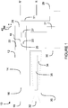
- an engine assembly 10 is generally shown. As should become more readily apparent throughout this document, the engine assembly 10 is configured such that it provides at least one dedicated voltage bus 11.
- the engine assembly 10 uses a compounding series configuration. This may allow for the electric power to come from one spool within a turbomachinery mechanically coupled to a final load or from split spools.
- the engine assembly 10 is a compound cycle engine system or compound cycle engine such as described in Lents et al.'s US patent No. 7,753,036 issued July 13, 2010 or as described in Julien et al.'s US patent No. 7,775,044 issued August 17, 2010 , or as described in Thomassin et al.'s U.S. patent publication No. 2015/0275749 published October 1, 2015 , or as described in Bolduc et al.'s U.S. patent publication No. 2015/0275756 published October 1, 2015 .
- the compound cycle engine system may be used as a prime mover engine, such as on an aircraft or other vehicle, or in any other suitable application.
- the engine assembly 10 may also be known as a powerplant.
- the engine assembly 10 is an auxiliary power unit (APU), also known as a range extender.
- APU auxiliary power unit
- the engine assembly 10 may accommodate for a portion of mechanical, electrical, hydraulic and/or pneumatic power source.
- the engine assembly 10 comprises a heat engine 12 such as an internal combustion engine.
- the heat engine 12 comprises one or more rotary engines, for example Wankel engines, or one or more reciprocating pistons.
- the heat engine 12 drives an engine shaft 14 having a first end 16 and a second end 18.
- the first end 16 is used for driving a rotatable load (not shown) via a mechanical output 19 of a mechanical gearbox 20.
- the mechanical gearbox 20 may comprise one or more gears and/or gear trains for providing speed and/or torque conversions from the first end 16 of the engine shaft 14 to the rotatable load via the mechanical output 19.
- the engine assembly 10 comprises an electric generator 22 for producing an electrical output.
- the electrical output may be referred to as a generator output voltage.
- the generator output voltage is an AC (alternating current) voltage.
- the second end 18 of the engine shaft 14 is used for driving the generator 22 when the heat engine 12 is in operation such that the electrical output can be produced.
- the generator 22 is separate from the gearbox 20, which may eliminate the need for a DC (direct current) generator and/or an AC alternator, which may conventionally be found in the mechanical gearbox 20 for providing AC and DC buses in aircrafts.
- the engine assembly 10 comprises one or more high power density permanent magnets.
- a high power density permanent magnet 25 may be directly integrated with the engine shaft 14 and a winding 23 may be directly integrated with the generator 22.
- the high power density permanent magnet 25 is directly attached to the engine shaft 14 proximate the second end 18 to provide a rotor, thereby electromagnetically coupling the generator 22 to the second end 18.
- the winding 23 may be directly attached to the generator 22 to provide a stator.
- the high power density permanent magnet 25 is not integrated inside the engine but is cantilevered off of the engine shaft 14.
- the permanent magnet 25 is directly attached to the engine shaft 14 and is supported by bearings that rotate the engine shaft 14. Other suitable configurations of the high power density permanent magnets may be possible. It should be appreciated that, by using high power density permanent magnet 25, the generator 22 used in practical implementation may be smaller than using an induction generator. Still, in other embodiments, the generator 22 is an induction generator.
- the generator 22 is a starter-generator, which may also be known as a motor-generator. That is, in some embodiments, the generator 22 is a starter for starting the heat engine 12 by driving the second end 18 of the engine shaft 14. In embodiments where the generator 22 is a starter-generator for starting the heat engine 12, this may eliminate the need for a separate starter which would conventionally be provided in the gearbox 20.
- the combination of the heat engine 12 and the generator 22 may be referred to as a hybrid-electric drive.
- the generator 22 can be used for example to drive rotors of a vertical lift vehicle.
- the heat engine 12 can be turned off, or can run on pilot injection only (e.g., five times less fuel than idle mode) so that emergency power is readily available, during take-off and landing, while the generator 22 drives the rotors under battery power; the heat engine 12 may be turned on during flight to drive the electric generator and recharge a battery 31.
- pilot injection only e.g., five times less fuel than idle mode
- the engine assembly 10 comprises a compressor 32 for compressing the air before it is fed to the intake of the heat engine 12, and a turbine section 34 receiving the exhaust gases from the heat engine 12. It is understood that variations are possible, and that, for example, the compressor 32 and/or turbine section 34 may be omitted.
- the heat engine 12, the compressor 32, and the turbine section 34 are in driving engagement with the gearbox 20.
- the gearbox 20 may be configured to allow the turbine section 34 via the turbine shaft 35 to compound power with the engine shaft 14 and to allow the turbine section 34 and/or the heat engine 12 to drive the compressor 32.
- the compressor 32, the turbine section 34, and the gearbox 20 are serially disposed along a rotational axis R.
- a rotational axis R' of the heat engine 12 is radially offset from the rotational axis R of the compressor 32 and of the turbine section 34.
- shafts 14, 35 are used to connect the compressor 32, the turbine section 34, and the heat engine 12 to the gearbox 20, respectively.
- Alternate configurations are possible, including, but not limited to, the compressor 32, turbine section 34, and heat engine 12 disposed coaxially, or the shafts 14, 35 extending at an angle (perpendicularly or otherwise) to each other.
- the compressor 32 may be located at any other suitable position.
- the compressor 32 may rotate at the same or different speed from the turbine shaft 35.
- the engine assembly 10 may comprise a thermal cooling system (not illustrated).
- the thermal cooling system may direct coolant to the heat engine 12 and/or the generator 22.
- a common thermal cooling system is used to cool the heat engine 12 and the generator 22.
- the engine assembly 10 may comprise an oil system (not illustrated).
- the oil system may direct lubricant to the heat engine 12 and/or the generator 22.
- a common oil system is used to lubricate the heat engine 12 and the generator 22.
- the engine assembly 10 comprises a power electronics module 26 connected to the electrical generator 22.
- the power electronics module 26 is configured for converting the electrical output of the generator 22 to produce a regulated output voltage.
- the output voltage is a direct current (DC) voltage output having a given voltage level.
- the output voltage is an alternating current (AC) voltage output having a given voltage level and a given frequency.
- the power electronics module 26 may comprise a controller 27 for adjusting the output voltage level and/or frequency of the output voltage produced by the generator 22.
- the power electronics module 26 may convert an AC electrical output of the generator 22 to a DC voltage output.
- the power electronics module 26 may convert an AC electrical output of the generator 22 to a different AC electrical output.
- the power electronics module 26 may be directly integrated with the generator 22. In other cases, the power electronics module 26 is external to the generator 22.
- the power electronics module 26 may comprise any suitable converter, regulator, transformer and/or any other suitable electronic circuitry.
- the power electronics module 26 may be configured to provide a regulated output voltage that meets an electrical power demand of at least one accessory 29.
- the power electronics module 26 may be configured to maintain the DC voltage at a substantially constant level in response to a changing power demand of the at least one aircraft accessory 29. That is, the power electronics module 26 may be configured to adjust the output current to keep the DC voltage level constant.
- the power electronics module 26 may be configured to maintain a frequency of the AC voltage substantially constant and/or a root mean square (RMS) level of the AC voltage substantially constant, in response to a changing power demand of the at least one aircraft accessory 29.
- RMS root mean square
- the dedicated voltage bus 11 is connected to the power electronics module 26.
- the dedicated voltage bus 11 is configured for supplying the regulated voltage output of the power electronics module 26 to the at least one accessory 29.
- the dedicated voltage bus 11 is a DC voltage bus (not illustrated).
- the dedicated voltage 11 bus is an AC voltage bus (not illustrated).
- the dedicated voltage bus 11 may be a high voltage bus, a medium voltage bus, a low voltage bus and/or any other suitable voltage bus.
- the output voltage level and/or frequency of dedicated voltage bus 11 may be set by the power electronics module 26.
- the dedicated voltage bus 11 can be provided. It should further be appreciated that in practical implementations, the generator 22 would typically be designed such that the output power of the generator 22 would be able to meet the power demand of the accessories 29 connected to the dedicated voltage bus 11.
- the dedicated voltage bus 11 can supply the output voltage at a level and/or frequency that is different from conventional voltage buses in aircrafts.
- conventional AC voltage buses in aircrafts are typically 115 to 120V AC with a 400Hz frequency.
- Conventional DC voltage buses in aircrafts are typically 28V DC or 14V DC. It should be appreciated that the conventional voltage level and/or frequency may not be suitable for certain accessories and/or may lead to energy inefficiencies.
- the dedicated voltage bus 11 is separate from the gearbox 20, which may eliminate the need for conventional AC and/DC voltage buses off of the gearbox 20.
- providing the dedicated voltage bus 11 directly from the generator 22 may eliminate the need for AC and/or DC mechanical drivers connected to the mechanical gearbox 20.
- the dedicated voltage bus 11 directly from the generator 22 may alleviate the need for local inverters.
- the dedicated voltage bus 11 is able to provide an AC voltage signal directly from the generator 22.
- an electronic engine control (EEC) 30 may communicate with the at least one accessory 29 to control the at least one accessory 29.
- the EEC 30 may instruct the accessory 29 to turn on and/or to turn off.
- the EEC may instruct the accessory 29 to increase and/or decrease its power consumption and hence the amount of power it draws from the dedicated voltage bus 11.
- the accessory 29 is a motor
- the EEC 30 may control the speed of the motor.
- the EEC 30 may be connected to one or more sensors (not illustrated) and/or an aircraft command system (not illustrated). The EEC 30 may control the accessory 29 in response to readings from the sensors and/or instructions from the aircraft command system.
- the EEC 30 may communicate with the controller 27 to instruct the controller 27 to adjust the output voltage provided to the at least one accessory 29 via the voltage bus 11.
- the EEC 30 may direct the controller 27 to adjust the output voltage level and/or frequency in response to a request from the aircraft command system and/or in response to a reading of the sensor.
- the EEC 30 may select a specific output voltage level and/or frequency and instruct the controller 27 to adjust power electronics module 26 accordingly to provide the specific output voltage level and/or frequency.
- the EEC 30 directly instructs the at least one accessory 29 to adjust its voltage and/or frequency.
- the EEC 30 may direct the at least one accessory 29 to adjust the output voltage level and/or frequency in response to a request from the aircraft command system and/or in response to a reading of the sensor.
- the EEC 30 may select a specific output voltage level and/or frequency and instruct the at least one accessory 29 to adjust power electronics module 26 accordingly to provide the specific output voltage level and/or frequency.
- the EEC 30 may instruct the generator 22 (via the controller 27) to adjust its output power and/or adjust its input power.
- the generator 22 may be in either a starting mode or a generating mode. When in the starting mode, the generator 22 is used as a starter and when in the generating mode, the generator 22 is used as a generator.
- EEC 30 may be separate from or integrated with the controller 27, depending on the implementation.
- the accessory 29 may be a motor, a linear actuator, a rotary actuator, an electric-mechanical machine, a hydraulic valve, a pneumatic value electrically connected, and/or any other suitable device.
- the accessory 29 may be any suitable electrical, mechanical, pneumatic and/or hydraulic device.
- the accessory 29 is an electric cooling fan.
- the power consumption of the electric cooling fan would typically depend on the rotational speed of the cooling fan.
- the EEC 30 may control the rotational speed of the electric cooling fan depending on cooling requirements.
- the EEC 30 may receive a temperature signal from a temperature sensor (not illustrated), process the temperature signal, and instruct the electric cooling fan to operate accordingly.
- the cooling fan may have a controllable fan speed which depends of the voltage level supplied thereto. For example, an increase in the voltage level supplied to the cooling fan would result in the cooling fan rotating faster, while a decrease in the voltage level supplied to the fan would result in the cooling fan rotating slower.
- the power electronics module 26 may adjust the level of voltage supplied to the cooling fan via the voltage bus 11 such that fan speed can be adjusted depending on cooling requirements.
- the EEC 30 may send one or more control signals to the controller 27 such that the power electronics module 26 controls the voltage level supplied to the cooling fan.
- an electric cooling fan connected to the dedicated voltage bus 11, where the electric cooling fan is controllable depending on cooling requirements would typically use less power than a conventional fan powered by mechanical power.
- a mechanical power output would typically be designed to operate the conventional fan at a worst case hot temperature condition. For example, if the conventional fan requires 40 kW of power to operate in worst case high temperature conditions, a mechanical driver connected to the mechanical gearbox 20 would conventionally be designed to consume 40 kW during aircraft operation regardless of the current temperature condition typically leading to energy inefficiencies.
- the accessory 29 is an electric motor for driving a wheel for taxiing of the aircraft.
- the electric motor may have a controllable rotational speed for driving the wheel.
- the aircraft command system may send signals to the EEC 30 which in turn controls the electric motor of the driving wheel.
- the electric motor for taxiing may be a low weight motor that is typically lighter than a conventional motor used for taxiing in aircrafts.
- the dedicated voltage bus 11 may indeed provide a high voltage level, which may be higher than a voltage level of a conventional aircraft voltage bus, allowing for a lower weight motor to be used.
- the accessory 29 is an actuator for controlling a guided vane of the aircraft.
- the accessory 29 may be any suitable accessory that requires power in an aircraft and the example accessories described herein are for example purposes only.
- Other accessories may include accessories having voltage input level and/or frequency requirements different from the voltage output level and/or frequency of conventional voltage buses in aircrafts.
- FIG. 11 While only a single dedicated voltage bus 11 and a single accessory 29 are illustrated in Figure 1 , this is for illustration purposes only. Depending on the practical implementation, multiple dedicated voltage buses as in 11 may be provided for supplying power to multiple accessories. For example, if the aircraft includes a plurality of accessories as in 29, each of the accessories may have its own dedicated voltage bus from a plurality of dedicated voltage buses. In other cases, multiple accessories may share a single dedicated voltage bus. It should be appreciated that the voltage level and/or frequency of each bus in the plurality of voltage buses may vary from each other.
- the engine assembly 10 comprises one or more batteries 31.
- the batteries 31 may be used to supply power to the generator 22 such that the generator 22 is able to start the heat engine 12.
- the batteries 31 may be used to drive the accessory 29.
- the generator 22 may be used to charge the batteries 31.
- the batteries 31 may contribute to the mechanical load drive as required depending on the design choices in terms of electrical power proportion.
- an AC voltage bus 42 and a DC voltage bus 44 having an output voltage level and/or frequency corresponding to that of conventional aircraft voltage buses may also be provided by the power electronics module 26 to supply power to other accessories (not illustrated). While, the output voltage level and/or frequency of the AC voltage bus 42 and/or the DC voltage bus 44 may correspond to that of conventional aircraft voltage buses, the conventional aircraft voltage buses would have typically been provided off of the mechanical accessory gearbox 20.
- the heat engine 12 is an internal combustion engine.
- the engine assembly 10 may be used as a continuously variable load or generator using current phase shift in order to reduce the combustion engine output torque ripple content, cancel undesirable harmonics or to avoid resonances of the combustion engine with its load.
- the engine assembly 10 may be used to compensate for irregularities in the power output of the combustion engine that can exist in abnormal circumstances such as when one or more of the engine power generating elements (pistons, rotors, etc.) have reduced power output.
- the EEC (reference 30 in Figure 1 ) and/or the controller (reference 27 in Figure 1 ) of the power electronics (reference 26 in Figure 1 ) may be implemented by a computing device 210, comprising a processing unit 212 and a memory 214 which has stored therein computer-executable instructions 216.
- the processing unit 212 may comprise any suitable devices such that instructions 216, when executed by the computing device 210 or other programmable apparatus, may cause the functions/acts/steps of any methods as described herein to be executed.
- the processing unit 212 may comprise, for example, any type of general-purpose microprocessor or microcontroller, a digital signal processing (DSP) processor, a central processing unit (CPU), an integrated circuit, a field programmable gate array (FPGA), a reconfigurable processor, other suitably programmed or programmable logic circuits, or any combination thereof.
- DSP digital signal processing
- CPU central processing unit
- FPGA field programmable gate array
- reconfigurable processor other suitably programmed or programmable logic circuits, or any combination thereof.
- the memory 214 may comprise any suitable known or other machine-readable storage medium.
- the memory 214 may comprise non-transitory computer readable storage medium, for example, but not limited to, an electronic, magnetic, optical, electromagnetic, infrared, or semiconductor system, apparatus, or device, or any suitable combination of the foregoing.
- the memory 214 may include a suitable combination of any type of computer memory that is located either internally or externally to a device, for example random-access memory (RAM), read-only memory (ROM), compact disc read-only memory (CDROM), electro-optical memory, magneto-optical memory, erasable programmable read-only memory (EPROM), and electrically-erasable programmable read-only memory (EEPROM), Ferroelectric RAM (FRAM) or the like.
- Memory 214 may comprise any storage means (e.g., devices) suitable for retrievably storing machine-readable instructions 216 executable by processing unit 212.
- Functionality of the EEC 30 and/or the controller 27 of the power electronics module 26 described herein may be implemented in a high level procedural or object oriented programming or scripting language, or a combination thereof, to communicate with or assist in the operation of a computer system, for example the computing device 210.
- functionality of the EEC 30 and/or the controller 27 of the power electronics module 26 may be implemented in assembly or machine language.
- the language may be a compiled or interpreted language.
- Program code for implementing functionality of the EEC 30 and/or the controller 27 of the power electronics module 26 may be stored on a storage media or a device, for example a ROM, a magnetic disk, an optical disc, a flash drive, or any other suitable storage media or device.
- the program code may be readable by a general or special-purpose programmable computer for configuring and operating the computer when the storage media or device is read by the computer to perform the procedures described herein.
- Functionality of the EEC 30 and/or the controller 27 of the power electronics module 26 may also be considered to be implemented by way of a non-transitory computer-readable storage medium having a computer program stored thereon.
- the computer program may comprise computer-readable instructions which cause a computer, or in some embodiments the processing unit 212 of the computing device 210, to operate in a specific and predefined manner to perform the functions described herein.
- Computer-executable instructions may be in many forms, including program modules, executed by one or more computers or other devices.
- program modules include routines, programs, objects, components, data structures, etc., that perform particular tasks or implement particular abstract data types.
- functionality of the program modules may be combined or distributed as desired in various embodiments.
Landscapes
- Engineering & Computer Science (AREA)
- Mechanical Engineering (AREA)
- Chemical & Material Sciences (AREA)
- Combustion & Propulsion (AREA)
- General Engineering & Computer Science (AREA)
- Power Engineering (AREA)
- Aviation & Aerospace Engineering (AREA)
- Control Of Eletrric Generators (AREA)
- Connection Of Motors, Electrical Generators, Mechanical Devices, And The Like (AREA)
Applications Claiming Priority (1)
| Application Number | Priority Date | Filing Date | Title |
|---|---|---|---|
| US201762509921P | 2017-05-23 | 2017-05-23 |
Publications (2)
| Publication Number | Publication Date |
|---|---|
| EP3416260A2 true EP3416260A2 (de) | 2018-12-19 |
| EP3416260A3 EP3416260A3 (de) | 2019-03-06 |
Family
ID=62386008
Family Applications (1)
| Application Number | Title | Priority Date | Filing Date |
|---|---|---|---|
| EP18173926.9A Pending EP3416260A3 (de) | 2017-05-23 | 2018-05-23 | Motoranordnung mit einem dedizierten spannungsbus |
Country Status (3)
| Country | Link |
|---|---|
| US (1) | US11124311B2 (de) |
| EP (1) | EP3416260A3 (de) |
| CA (1) | CA3005542A1 (de) |
Families Citing this family (8)
| Publication number | Priority date | Publication date | Assignee | Title |
|---|---|---|---|---|
| JP6568158B2 (ja) * | 2017-07-28 | 2019-08-28 | 株式会社Subaru | 車両用制御装置 |
| WO2020180367A1 (en) | 2019-03-01 | 2020-09-10 | United Technologies Advanced Projects Inc. | Torque balancing for hybrid electric propulsion systems and aircraft utilizing hybrid electric propulsion systems |
| US11628942B2 (en) * | 2019-03-01 | 2023-04-18 | Pratt & Whitney Canada Corp. | Torque ripple control for an aircraft power train |
| US11732639B2 (en) | 2019-03-01 | 2023-08-22 | Pratt & Whitney Canada Corp. | Mechanical disconnects for parallel power lanes in hybrid electric propulsion systems |
| US11697505B2 (en) | 2019-03-01 | 2023-07-11 | Pratt & Whitney Canada Corp. | Distributed propulsion configurations for aircraft having mixed drive systems |
| WO2020190344A2 (en) | 2019-03-18 | 2020-09-24 | United Technologies Advanced Projects Inc. | Architectures for hybrid-electric propulsion |
| US11486472B2 (en) | 2020-04-16 | 2022-11-01 | United Technologies Advanced Projects Inc. | Gear sytems with variable speed drive |
| US11926426B2 (en) * | 2021-03-19 | 2024-03-12 | Pratt & Whitney Canada Corp. | Electric distributed propulsion using exhaust recovery power |
Citations (4)
| Publication number | Priority date | Publication date | Assignee | Title |
|---|---|---|---|---|
| US7753036B2 (en) | 2007-07-02 | 2010-07-13 | United Technologies Corporation | Compound cycle rotary engine |
| US7775044B2 (en) | 2003-02-24 | 2010-08-17 | Pratt & Whitney Canada Corp. | Low volumetric compression ratio integrated turbo-compound rotary engine |
| US20150275756A1 (en) | 2012-07-20 | 2015-10-01 | Pratt & Whitney Canada | Compound cycle engine |
| US20150275749A1 (en) | 2012-07-20 | 2015-10-01 | Pratt & Whitney Canada Corp. | Compound cycle engine |
Family Cites Families (22)
| Publication number | Priority date | Publication date | Assignee | Title |
|---|---|---|---|---|
| US6717282B1 (en) * | 2002-07-03 | 2004-04-06 | William J. Maxwell | Combined motor and generator dynamometer system |
| US20040090204A1 (en) * | 2002-11-12 | 2004-05-13 | Honeywell International Inc. | Electric motor driven engine accessories |
| US6906432B2 (en) * | 2003-07-02 | 2005-06-14 | Mes International, Inc. | Electrical power generation system and method |
| US6931856B2 (en) * | 2003-09-12 | 2005-08-23 | Mes International, Inc. | Multi-spool turbogenerator system and control method |
| US7468561B2 (en) * | 2007-03-27 | 2008-12-23 | General Electric Company | Integrated electrical power extraction for aircraft engines |
| US8201523B2 (en) | 2008-06-27 | 2012-06-19 | Cohen Kenneth J | Integrated combustion and electric hybrid engines and methods of making and use thereof |
| US8291716B2 (en) * | 2008-10-08 | 2012-10-23 | The Invention Science Fund I Llc | Hybrid propulsive engine including at least one independently rotatable turbine stator |
| US8395274B2 (en) * | 2009-04-15 | 2013-03-12 | Hamilton Sundstrand Corporation | Integrated power unit as energy storage device for electrical power system |
| FR2962404B1 (fr) * | 2010-07-08 | 2012-07-20 | Eurocopter France | Architecture electrique pour aeronef a voilure tournante a motorisation hybride |
| US9212625B2 (en) | 2010-11-19 | 2015-12-15 | Rudolph Allen SHELLEY | Hybrid gas turbine propulsion system |
| FR2975547B1 (fr) * | 2011-05-20 | 2013-06-07 | Turbomeca | Procede de rationalisation de chaine de composants electriques d'un aeronef, architecture de mise en oeuvre et aeronef correspondant |
| US20130062885A1 (en) | 2011-09-08 | 2013-03-14 | General Electric Company | Method and apparatus for extracting electrical power from a gas turbine engine |
| US9002552B2 (en) | 2011-09-21 | 2015-04-07 | GM Global Technology Operations LLC | Compact electric range extender for an electric vehicle |
| US20130232941A1 (en) | 2012-03-07 | 2013-09-12 | Ge Aviation Systems Llc | Apparatus for extracting input power from the low pressure spool of a turbine engine |
| US9194232B2 (en) * | 2012-07-20 | 2015-11-24 | Pratt & Whitney Canada Corp. | Compound cycle engine |
| GB2520024B (en) * | 2013-11-06 | 2016-02-03 | Ge Aviat Systems Ltd | Electrical power system for an aircraft |
| US10090676B2 (en) | 2015-06-03 | 2018-10-02 | Northrop Grumman Systems Corporation | Aircraft DC power distribution systems and methods |
| US10696417B2 (en) | 2015-06-25 | 2020-06-30 | Pratt & Whitney Canada Corp. | Auxiliary power unit with excess air recovery |
| EP3124379B1 (de) * | 2015-07-29 | 2019-05-01 | Airbus Defence and Space GmbH | Hybrid-elektrischer antriebsstrang für vtol drohnen |
| US10814991B2 (en) | 2015-11-09 | 2020-10-27 | General Electric Company | Propulsion system and methods of use thereof |
| US10293804B2 (en) | 2016-05-19 | 2019-05-21 | GM Global Technology Operations LLC | Hybrid vehicle engine starter systems and methods |
| US10112603B2 (en) * | 2016-12-14 | 2018-10-30 | Bendix Commercial Vehicle Systems Llc | Front end motor-generator system and hybrid electric vehicle operating method |
-
2018
- 2018-05-18 CA CA3005542A patent/CA3005542A1/en active Pending
- 2018-05-18 US US15/983,528 patent/US11124311B2/en active Active
- 2018-05-23 EP EP18173926.9A patent/EP3416260A3/de active Pending
Patent Citations (4)
| Publication number | Priority date | Publication date | Assignee | Title |
|---|---|---|---|---|
| US7775044B2 (en) | 2003-02-24 | 2010-08-17 | Pratt & Whitney Canada Corp. | Low volumetric compression ratio integrated turbo-compound rotary engine |
| US7753036B2 (en) | 2007-07-02 | 2010-07-13 | United Technologies Corporation | Compound cycle rotary engine |
| US20150275756A1 (en) | 2012-07-20 | 2015-10-01 | Pratt & Whitney Canada | Compound cycle engine |
| US20150275749A1 (en) | 2012-07-20 | 2015-10-01 | Pratt & Whitney Canada Corp. | Compound cycle engine |
Also Published As
| Publication number | Publication date |
|---|---|
| US20180339786A1 (en) | 2018-11-29 |
| US11124311B2 (en) | 2021-09-21 |
| EP3416260A3 (de) | 2019-03-06 |
| CA3005542A1 (en) | 2018-11-23 |
Similar Documents
| Publication | Publication Date | Title |
|---|---|---|
| EP3416260A2 (de) | Motoranordnung mit einem dedizierten spannungsbus | |
| US9446842B2 (en) | Hybrid power rotary wing aircraft | |
| US11548651B2 (en) | Asymmeiric hybrid aircraft idle | |
| US10906657B2 (en) | Aircraft system with distributed propulsion | |
| US7188475B2 (en) | Starting and controlling speed of a two spool gas turbine engine | |
| US9776583B2 (en) | Aircraft electrical system | |
| US9873518B2 (en) | Electrical architecture for an aircraft, an aircraft, and a method of using it | |
| EP2985901B1 (de) | Hybrides elektrisches impulsenergieantriebssystem für flugzeug | |
| CN1076140C (zh) | 用于涡轮/交流发电机的共轴电气系统 | |
| US7250688B2 (en) | Narrow range variable frequency starter/generator system | |
| US20160257416A1 (en) | Propulsion system | |
| US20080121444A1 (en) | Straddle carrier having a low-emission and low-maintenance turbine drive | |
| US20210237887A1 (en) | Propulsion system for a helicopter | |
| EP2988413A1 (de) | Elektrische systemarchitektur für mehr elektrisches motorzubehör | |
| US4724331A (en) | Method and apparatus for starting an aircraft engine | |
| US20240175397A1 (en) | Method for the piloted start-up of a gas turbine of an aircraft, and corresponding system | |
| CN117585170A (zh) | 一种分布式多桨垂直起降飞行器混合动力系统及管理方法 | |
| CN104052194B (zh) | 汽车中的带有转速信号输入端的电机 | |
| EP4401285A1 (de) | Elektrisches energiesystem mit verschiedenen axialen längen zur effizienten stromerzeugung | |
| EP3496244B1 (de) | Druckluftturbinengleichstromgeneratorsystem | |
| US20160036363A1 (en) | Systems utilizing a controllable voltage ac generator system | |
| US20210122488A1 (en) | Aircraft auxiliary power unit | |
| EP4456411A2 (de) | Motorstartsystem mit erreger | |
| EP4477555A1 (de) | Elektromechanisch gesteuertes flugzeugkraftübertragungssystem | |
| US20170267369A1 (en) | Motor-generator for high efficiency auxiliary power system |
Legal Events
| Date | Code | Title | Description |
|---|---|---|---|
| PUAI | Public reference made under article 153(3) epc to a published international application that has entered the european phase |
Free format text: ORIGINAL CODE: 0009012 |
|
| STAA | Information on the status of an ep patent application or granted ep patent |
Free format text: STATUS: THE APPLICATION HAS BEEN PUBLISHED |
|
| AK | Designated contracting states |
Kind code of ref document: A2 Designated state(s): AL AT BE BG CH CY CZ DE DK EE ES FI FR GB GR HR HU IE IS IT LI LT LU LV MC MK MT NL NO PL PT RO RS SE SI SK SM TR |
|
| AX | Request for extension of the european patent |
Extension state: BA ME |
|
| PUAL | Search report despatched |
Free format text: ORIGINAL CODE: 0009013 |
|
| AK | Designated contracting states |
Kind code of ref document: A3 Designated state(s): AL AT BE BG CH CY CZ DE DK EE ES FI FR GB GR HR HU IE IS IT LI LT LU LV MC MK MT NL NO PL PT RO RS SE SI SK SM TR |
|
| AX | Request for extension of the european patent |
Extension state: BA ME |
|
| RIC1 | Information provided on ipc code assigned before grant |
Ipc: B64D 41/00 20060101ALI20190128BHEP Ipc: H02J 1/00 20060101ALI20190128BHEP Ipc: H02J 4/00 20060101AFI20190128BHEP Ipc: B64C 25/40 20060101ALI20190128BHEP Ipc: H02J 3/00 20060101ALI20190128BHEP Ipc: H02J 5/00 20160101ALI20190128BHEP Ipc: H02J 7/14 20060101ALI20190128BHEP Ipc: F01D 15/10 20060101ALI20190128BHEP Ipc: B64D 27/00 20060101ALI20190128BHEP |
|
| STAA | Information on the status of an ep patent application or granted ep patent |
Free format text: STATUS: REQUEST FOR EXAMINATION WAS MADE |
|
| 17P | Request for examination filed |
Effective date: 20190906 |
|
| RBV | Designated contracting states (corrected) |
Designated state(s): AL AT BE BG CH CY CZ DE DK EE ES FI FR GB GR HR HU IE IS IT LI LT LU LV MC MK MT NL NO PL PT RO RS SE SI SK SM TR |
|
| STAA | Information on the status of an ep patent application or granted ep patent |
Free format text: STATUS: EXAMINATION IS IN PROGRESS |
|
| 17Q | First examination report despatched |
Effective date: 20200122 |
|
| GRAP | Despatch of communication of intention to grant a patent |
Free format text: ORIGINAL CODE: EPIDOSNIGR1 |
|
| STAA | Information on the status of an ep patent application or granted ep patent |
Free format text: STATUS: GRANT OF PATENT IS INTENDED |
|
| RIC1 | Information provided on ipc code assigned before grant |
Ipc: H02J 4/00 20060101AFI20260223BHEP Ipc: H02J 7/14 20060101ALI20260223BHEP Ipc: F01D 15/10 20060101ALI20260223BHEP Ipc: H02J 3/00 20060101ALI20260223BHEP Ipc: H02J 1/00 20060101ALI20260223BHEP Ipc: B64D 27/00 20060101ALI20260223BHEP Ipc: B64D 41/00 20060101ALI20260223BHEP Ipc: B64C 25/40 20060101ALI20260223BHEP |
|
| INTG | Intention to grant announced |
Effective date: 20260306 |